yy_mjk_icops2009_01
DESCRIPTION
EFFECT OF PRESSURE AND ELECTRODE SEPARATION ON PLASMA UNIFORMITY IN DUAL FREQUENCY CAPACITIVELY COUPLED PLASMA TOOLS * Yang Yang a) and Mark J. Kushner b) a) Department of Electrical and Computer Engineering Iowa State University, Ames, IA 50011, USA [email protected] - PowerPoint PPT PresentationTRANSCRIPT

EFFECT OF PRESSURE AND ELECTRODE SEPARATION ON PLASMA UNIFORMITY IN
DUAL FREQUENCY CAPACITIVELY COUPLED PLASMA TOOLS *
Yang Yanga) and Mark J. Kushnerb)
a)Department of Electrical and Computer Engineering Iowa State University, Ames, IA 50011, USA
b)Department of Electrical Engineering and Computer ScienceUniversity of Michigan, Ann Arbor, MI 48109, USA
http://uigelz.eecs.umich.edu
June 2009
YY_MJK_ICOPS2009_01
* Work supported by Semiconductor Research Corp., Applied Materials and Tokyo Electron Ltd.

AGENDA
Optimization of multiple frequency plasma etching reactors
Description of the model
Scaling with:
Pressure
Electrode separation
Concluding remarks
YY_MJK_ICOPS2009_02
University of MichiganInstitute for Plasma Science & Engr.

MULTI-FREQUENCY PLASMA ETCHING REACTORS
State of the art plasma etching reactors use multiple frequencies to create the plasma and accelerate ions into the wafer.
Voltage finds its way into the plasma propagating around electrodes (not through them).
Ref: S. Rauf, AMAT University of MichiganInstitute for Plasma Science & Engr.YY_MJK_ICOPS2009_03

WAVE EFFECTSCHALLENGE SCALING
Lieberman, et al PSST 11 (2002)A. Perret, APhL 83 (2003)http://mrsec.wisc.edu
University of MichiganInstitute for Plasma Science & Engr.
As wafer size and frequencies increase - and wavelength decreases, “electrostatic” applied voltage takes on wavelike effects.
Plasma shortened wavelength:
= min(half plasma thickness, skin depth), s = sheath thickness
2/10 s1
YY_MJK_ICOPS2009_04

AN EXAMPLE: ADJUSTABLE GAP CONTROL
Adjusting the gap (electrode separation) of capacitively coupled plasmas (CCPs) enables customization of the radical fluxes.
Enables different processes, such as mask opening and trench etching, to be separately optimized.
V. Vahedi, M. Srinivasan, A. Bailey, Solid State Technology, 51, November, 2008. University of Michigan
Institute for Plasma Science & Engr.YY_MJK_ICOPS2009_05

Electromagnetic wave effects impact processing uniformity in high frequency CCPs.
When coupled with changing gap and pressure, controlling the plasma uniformity could be more difficult.
Results from a computational investigation of impacts of pressure and gap on plasma uniformity in dual frequency CCPs (DF-CCPs) will be discussed.
COUPLED EFFECTS IN HIGH FREQUENCY CCPs
University of MichiganInstitute for Plasma Science & Engr.YY_MJK_ICOPS2009_06

HYBRID PLASMA EQUIPMENT MODEL (HPEM)
Electron Energy Transport Module: Electron Monte Carlo Simulation
provides EEDs of bulk electrons Separate MCS used for secondary,
sheath accelerated electrons Fluid Kinetics Module:
Heavy particle and electron continuity, momentum, energy
Maxwell’s Equations Plasma Chemistry Monte Carlo Module:
IEADs onto wafer
E, N
Fluid Kinetics ModuleFluid equations
(continuity, momentum,
energy)Maxwell
Equations
Te,S,μ
Electron Energy Transport
Module
Plasma Chemistry Monte Carlo
ModuleUniversity of Michigan
Institute for Plasma Science & Engr.YY_MJK_ICOPS2009_07

Full-wave Maxwell solvers are challenging due to coupling between electromagnetic (EM) and sheath forming electrostatic (ES) fields.
EM fields are generated by rf sources and plasma currents
ES fields originate from charges.
We separately solve for EM and ES fields and sum the fields for plasma transport.
Boundary conditions (BCs):
EM field: Determined by rf sources.
ES field: Determined by blocking capacitor (DC bias) or applied DC voltages.
ESEMEE
METHODOLOGY OF THE MAXWELL SOLVER
University of MichiganInstitute for Plasma Science & Engr.YY_MJK_ICOPS2009_08

REACTOR GEOMETRY
2D, cylindrically symmetric.
Base conditions
Ar/CF4 =90/10, 400 sccm
High frequency (HF) upper electrode: 150 MHz, 300 W
Low frequency (LF) lower electrode: 10 MHz, 300 W
Specify power, adjust voltage.
Main species in Ar/CF4
mixture
Ar, Ar*, Ar+
CF4, CF3, CF2, CF, C2F4, C2F6, F, F2
CF3+, CF2
+, CF+, F+
e, CF3-, F-
YY_MJK_ICOPS2009_09
University of MichiganInstitute for Plasma Science & Engr.

10 mTorr, Max = 9.6 x 109 cm-3
[e]
Ar PLASMA IN SINGLE FREQUENCY CCP
50 mTorr, Max = 4.3 x 1010 cm-3
YY_MJK_ICOPS2009_10
With increasing Ar pressure, electron density transitions from center high to edge high.
Agrees with experimental trend, albeit in a different geometry.
DF-CCP at higher frequency, with electronegative gas…trends?
V. N. Volynets, et al., J. Vac. Sci. Technol. A 26, 406, 2008.
Ar, 100 MHz/750 W from upper electrode.
80 mTorr, Max = 1.5 x 1011 cm-3
University of MichiganInstitute for Plasma Science & Engr.

EM EFFECTS: FIELD IN SHEATHS HF = 50 MHz, Max = 410 V/cm
HF = 150 MHz, Max = 355 V/cm
Low frequency – electrostatic edge effect. High Frequency – Constructive interference of waves in center of
reactor.
Ar/CF4=90/10, 50 mTorr, 400 sccm HF: 300 W, LF: 10 MHz/300 W
University of MichiganInstitute for Plasma Science & Engr.
LF = 10 MHz, Max = 750 V/cm
YY_MJK_ICOPS2009_11
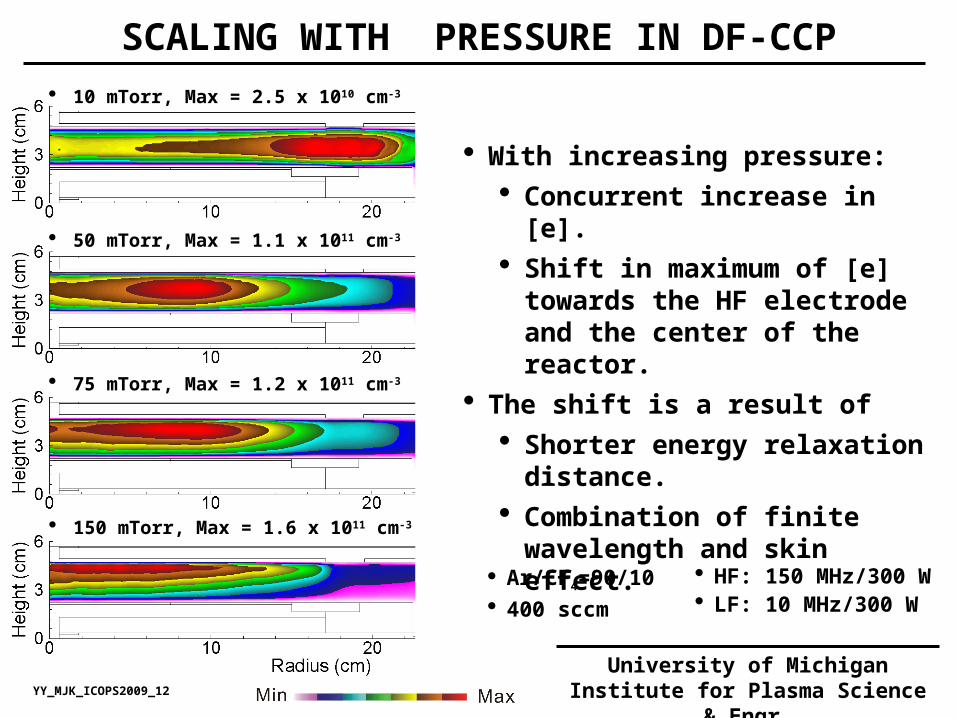
SCALING WITH PRESSURE IN DF-CCP 10 mTorr, Max = 2.5 x 1010 cm-3
50 mTorr, Max = 1.1 x 1011 cm-3
75 mTorr, Max = 1.2 x 1011 cm-3
150 mTorr, Max = 1.6 x 1011 cm-3
With increasing pressure: Concurrent increase in [e]. Shift in maximum of [e] towards
the HF electrode and the center of the reactor.
The shift is a result of Shorter energy relaxation
distance. Combination of finite
wavelength and skin effect.
Ar/CF4=90/10 400 sccm
HF: 150 MHz/300 W LF: 10 MHz/300 W
YY_MJK_ICOPS2009_12
University of MichiganInstitute for Plasma Science & Engr.
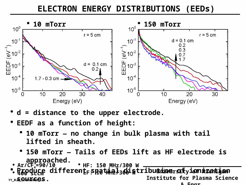
ELECTRON ENERGY DISTRIBUTIONS (EEDs)
d = distance to the upper electrode. EEDF as a function of height:
10 mTorr — no change in bulk plasma with tail lifted in sheath. 150 mTorr — Tails of EEDs lift as HF electrode is approached.
Produce different spatial distribution of ionization sources.
Ar/CF4=90/10 400 sccm
HF: 150 MHz/300 W LF: 10 MHz/300 W
YY_MJK_ICOPS2009_13
University of MichiganInstitute for Plasma Science & Engr.
150 mTorr 10 mTorr

ELECTRON IMPACT IONIZATION SOURCE (Se)
With increasing pressure: Axial direction: Energy relaxation distance decreases and so
sheath heating is dissipated close to electrode – transition to net attachment.
Radial direction: As energy relaxation distance decreases, Se mirrors the constructively interfered HF field - more center peaked. Ar/CF4=90/10
400 sccm
HF: 150 MHz/300 W LF: 10 MHz/300 W
YY_MJK_ICOPS2009_14
University of MichiganInstitute for Plasma Science & Engr.
Radial Direction (In the HF Sheath) Axial Direction

ION FLUX INCIDENT ON WAFER
With increasing pressure, ionization source increases but moves further from wafer..
Ar+ flux is depleted by charge exchange reactions while diffusing to wafer – and is maximum at 25-50 mTorr.
Flux of CF3+ Flux of Ar+
Ar/CF4=90/10 400 sccm
HF: 150 MHz/300 W LF: 10 MHz/300 W
YY_MJK_ICOPS2009_15
University of MichiganInstitute for Plasma Science & Engr.

Center Edge
10 mTorr Center Center Edge Edge
IEADs are separately collected over center and edge of wafer.
Bimodal to single peak transition with increasing pressure.
10 mTorr: uniform ≥50 mTorr: larger radial
variation.
Ar/CF4=90/10, 400 sccm HF: 150 MHz LF: 10 MHz/300 W
150 mTorr
YY_MJK_ICOPS2009_16
University of MichiganInstitute for Plasma Science & Engr.
TOTAL ION IEADs INCIDENT ON WAFER: Ar/CF4 = 90/10

SCALING WITH PRESSURE: Ar/CF4 =80/20 10 mTorr, Max = 2.5 x 1010 cm-3
50 mTorr, Max = 4.8 x 1010 cm-3
100 mTorr, Max = 4.5 x 1010 cm-3
150 mTorr, Max = 4.2 x 1010 cm-3
With increasing pressure: [e] decreases from 50 to 150
mTorr owing to increasing attachment losses.
Maximum of [e] still shifts towards the HF electrode and the reactor center…a less dramatic shift than Ar/CF4=90/10.
Electrostatic component remains dominant due to lower conductivity.
Ar/CF4=80/20 400 sccm
HF: 150 MHz/300 W LF: 10 MHz/300 W
YY_MJK_ICOPS2009_17
University of MichiganInstitute for Plasma Science & Engr.

ION FLUX INCIDENT ON WAFER: Ar/CF4 =80/20
Compared with Ar/CF4 = 90/10…
More rapid depletion of Ar+ flux by charge exchange.
CF3+ flux also maximizes at intermediate pressure —
consequence of more confined plasma.
Flux of CF3+ Flux of Ar+
Ar/CF4=80/20 400 sccm
HF: 150 MHz/300 W LF: 10 MHz/300 W
YY_MJK_ICOPS2009_18
University of MichiganInstitute for Plasma Science & Engr.

Center Edge
10 mTorr Center Center Edge Edge
At Ar/CF4 =80/20 plasma is peaked near HF electrode edge, and largely uniform over the surface of wafer.
Improved uniformity of IEADs at all pressures.
Ar/CF4=80/20, 400 sccm HF: 150 MHz LF: 10 MHz/300 W
150 mTorr
YY_MJK_ICOPS2009_19
University of MichiganInstitute for Plasma Science & Engr.
TOTAL ION IEADs INCIDENT ON WAFER: Ar/CF4 = 80/20

SCALING WITH GAP: Ar/CF4 =90/10 Gap = 1.5 cm, Max = 3.4 x 1010 cm-3
2.5 cm, Max = 1.1 x 1011 cm-3
With increasing gap: [e] increases as diffusion length
increases and loss decreases. Edge peaked [e] at gap = 1.5
cm, due to electrostatic edge effect.
Maximum of [e] shifts towards the HF electrode.
For gap > 2.5 cm, radial [e] profile is not sensitive to gap.
Electrode spacing exceeds energy relaxation length and power deposition mechanism does not change.
Ar/CF4=90/10 50 mTorr, 400 sccm
HF: 150 MHz/300 W LF: 10 MHz/300 W
3.5 cm, Max = 1.5 x 1011 cm-3
5.5 cm, Max = 1.6 x 1011 cm-3
YY_MJK_ICOPS2009_20
University of MichiganInstitute for Plasma Science & Engr.

2.5 cm: Little change across bulk plasma; tail in LF sheath lifted owing to HF wave penetration.
5.5 cm: Systematic tail enhancement towards the HF electrode — larger separation between HF and LF waves, system functions more linearly.
Ar/CF4=90/10 50 mTorr, 400 sccm HF: 150 MHz/300 W LF: 10 MHz/300 W
YY_MJK_ICOPS2009_21
University of MichiganInstitute for Plasma Science & Engr.
Gap = 5.5 cm Gap = 1.5 cm
EEDs vs GAP

ION FLUX INCIDENT ON WAFER
1.5 cm: edge peaked flux due to electrostatic edge effect. 2.5-5.5 cm: middle peaked flux due to electrostatic and wave
coupling. 6.5 cm: center peaked flux ( with a middle peaked [e] ): edge effect
reduced at larger gap.
Flux of CF3+ Flux of Ar+
Ar/CF4=90/10 50 mTorr, 400 sccm
HF: 150 MHz/300 W LF: 10 MHz/300 W
YY_MJK_ICOPS2009_22
University of MichiganInstitute for Plasma Science & Engr.

Center Edge
1.5 cm Center Center Edge Edge
Narrow gap has large center-to-edge non-uniformity due to change in sheath width.
Narrower sheath near edge produces broaded IEAD.
Large gap enables more diffusive and uniform sheath properties – and so more uniform IEADs.
Ar/CF4=90/10, 50 mTorr, 400 sccm HF: 150 MHz/300W LF: 10 MHz/300 W
5.5 cm
YY_MJK_ICOPS2009_23
University of MichiganInstitute for Plasma Science & Engr.
TOTAL ION IEADs INCIDENT ON WAFER vs GAP

CONCLUDING REMARKS
For DF-CCPs sustained in Ar/CF4=90/10 mixture with HF = 150 MHz:
With increasing pressure, maximum of ionization source (Se) shifts towards the HF electrode as energy relaxation distance decreases.
Se mirrors EM field, which is center peaked from constructive interference and [e] profile transitions from edge high to center high.
Increasing fraction of CF4 to 20% results in more uniform ion fluxes and IEADs incident on wafer.
Effects of gap size in Ar/CF4=90/10 mixture:
Between 2.5 and 6.5 cm, [e] profile is not sensitive to gap size since larger than energy relaxation distance.
Small gaps have more edge-to-center non-uniformity in IEADs due to strong edge effects.
YY_MJK_ICOPS2009_24
University of MichiganInstitute for Plasma Science & Engr.