your vehicle: your vehicle: 2010 audi q7 quattro (4lb) v6 ... · 14/04/2014 · your vehicle: your...
TRANSCRIPT
Welcome WAYNE SMITHWelcome WAYNE SMITH
Leading source of Online Diagnostic & Repair InformationLeading source of Online Diagnostic & Repair Information
Your Vehicle: Your Vehicle: 2010 Audi Q7 Quattro (4LB) V6-3.0L DSL Turbo (CATA)2010 Audi Q7 Quattro (4LB) V6-3.0L DSL Turbo (CATA)
VehicleVehicle » » Powertrain ManagementPowertrain Management » » Computers and Control SystemsComputers and Control Systems » » Main Relay (Computer/FuelMain Relay (Computer/FuelSystem)System) » » Technical Service BulletinsTechnical Service Bulletins » » All Technical Service BulletinsAll Technical Service Bulletins » » Computer/Controls Computer/Controls - - MIL ON,MIL ON,DTC P068A00. No StartDTC P068A00. No Start
Computer/Controls Computer/Controls - - MIL ON, DTC P068A00. No StartMIL ON, DTC P068A00. No Start
97 No start (DTC P068A00)
97 14 43
2036764/3
April 14, 2014
Supersedes Technical Service Bulletin Group 97 number 14-42 dated March 31, 2014 for reasons listed below.
Vehicle Information
Condition
Technical Background
The motronic engine control module power supply relay, J271, is not functioning properly. Because the J271 relay controls batteryvoltage (Terminal 30) via a ground signal sent from the ECM, numerous faults can occur in multiple control modules when it is notfunctioning properly.
Production Solution
Change of relay construction at Tyco Electronics. Installation of Hella relay in production.
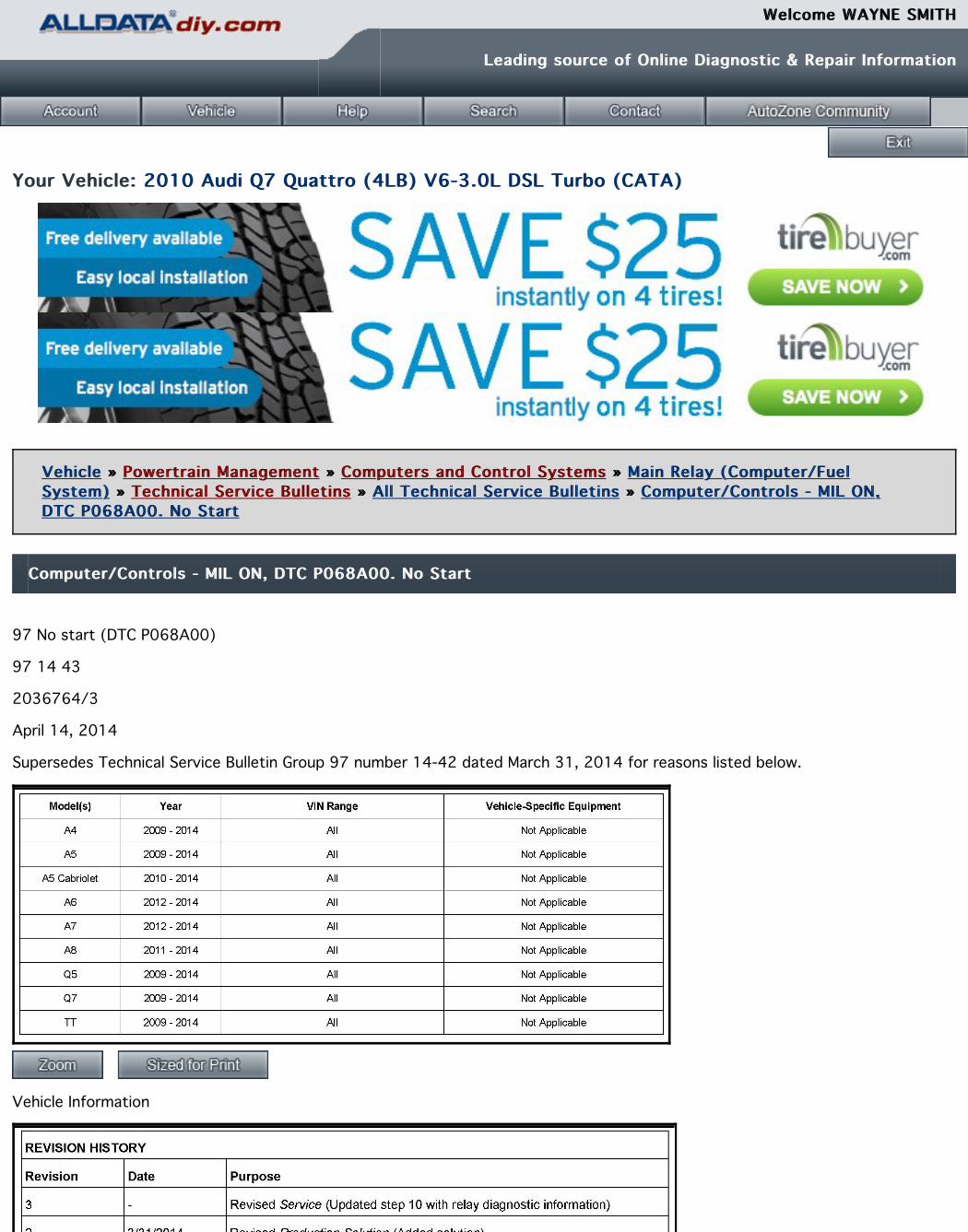
Service1. Confirm that DTC P068A00 is stored in the ECM, J623 (address word 01):
^ If DTC P068A00 is stored in the ECM, proceed with this bulletin.
^ If DTC P068A00 is not stored in the ECM, do not proceed with this bulletin. Continue with diagnosis. Tip: The images used inthis bulletin are of a 2014 A4 vehicle. Use Elsa to confirm component and connector terminal locations for the specific vehiclebeing repaired.
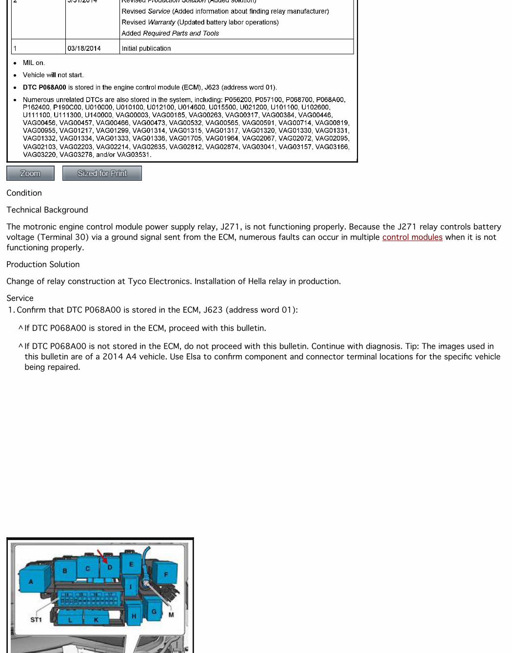
2. Check Elsa for the location of the J271 relay (Wiring diagrams >> Component locations >> Component Locations: Relays)(Figure 1).
3. Remove the plenum cover (Figure 2).
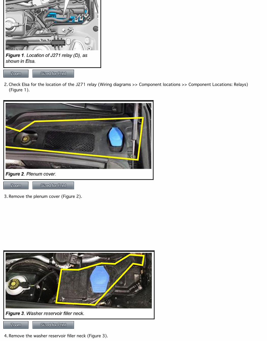
4. Remove the washer reservoir filler neck (Figure 3).
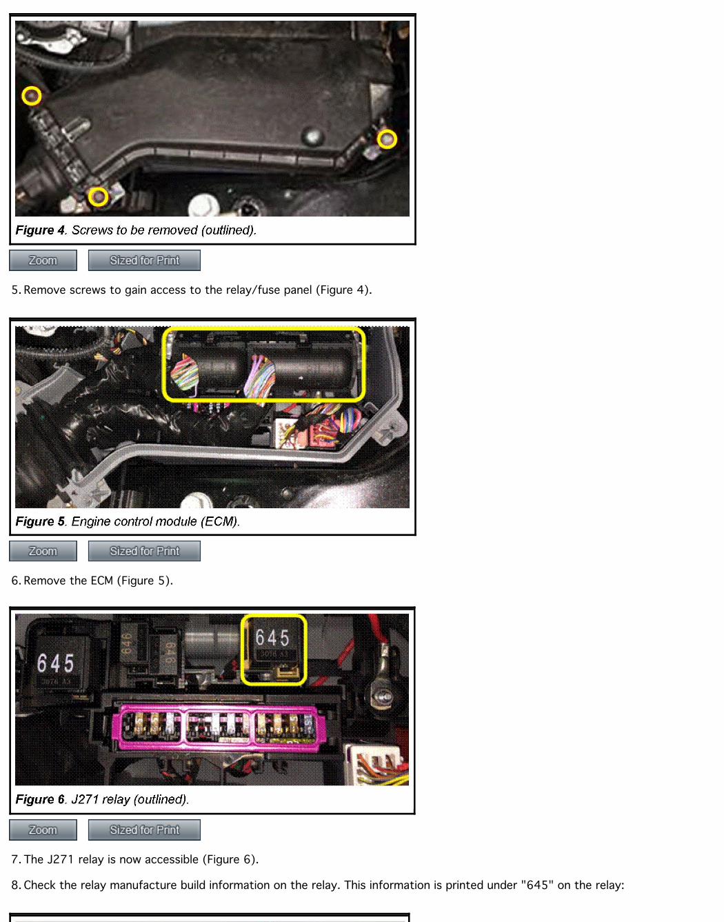
5. Remove screws to gain access to the relay/fuse panel (Figure 4).
6. Remove the ECM (Figure 5).
7. The J271 relay is now accessible (Figure 6).
8. Check the relay manufacture build information on the relay. This information is printed under "645" on the relay:
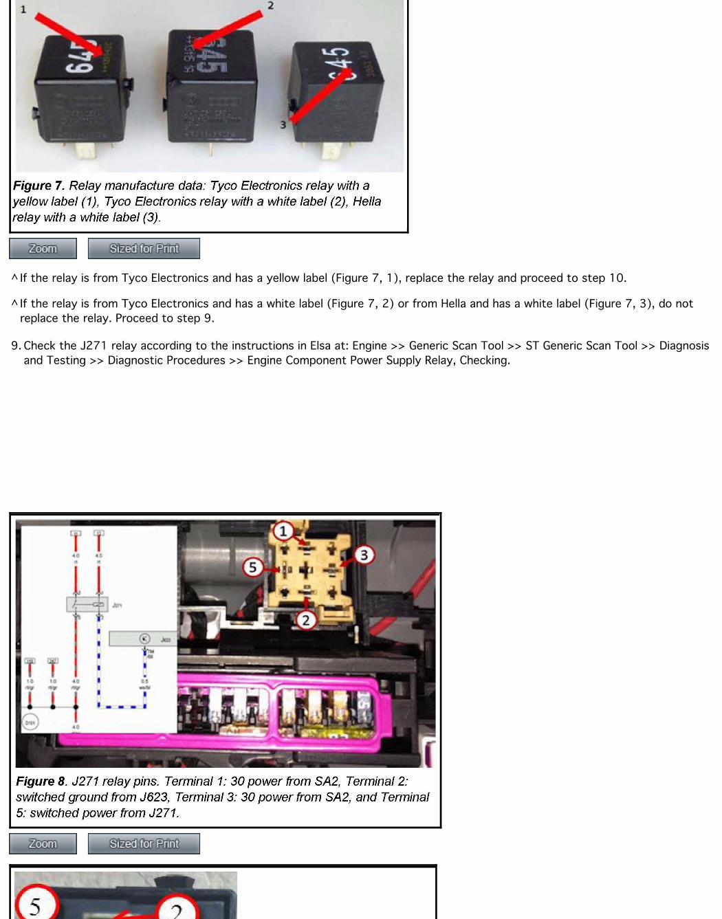
^ If the relay is from Tyco Electronics and has a yellow label (Figure 7, 1), replace the relay and proceed to step 10.
^ If the relay is from Tyco Electronics and has a white label (Figure 7, 2) or from Hella and has a white label (Figure 7, 3), do notreplace the relay. Proceed to step 9.
9. Check the J271 relay according to the instructions in Elsa at: Engine >> Generic Scan Tool >> ST Generic Scan Tool >> Diagnosisand Testing >> Diagnostic Procedures >> Engine Component Power Supply Relay, Checking.
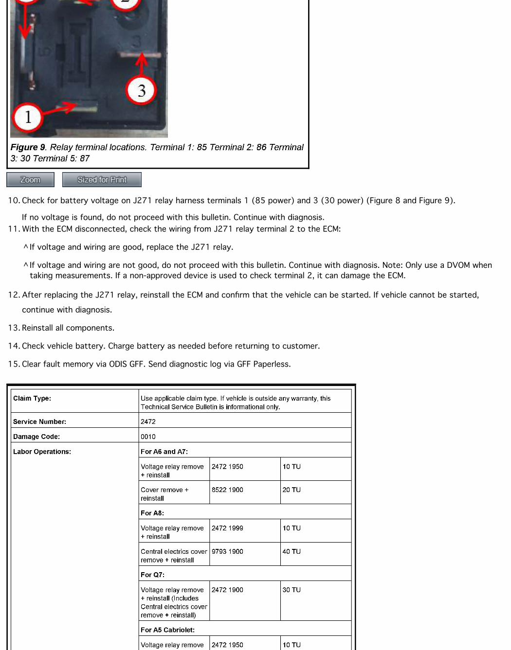
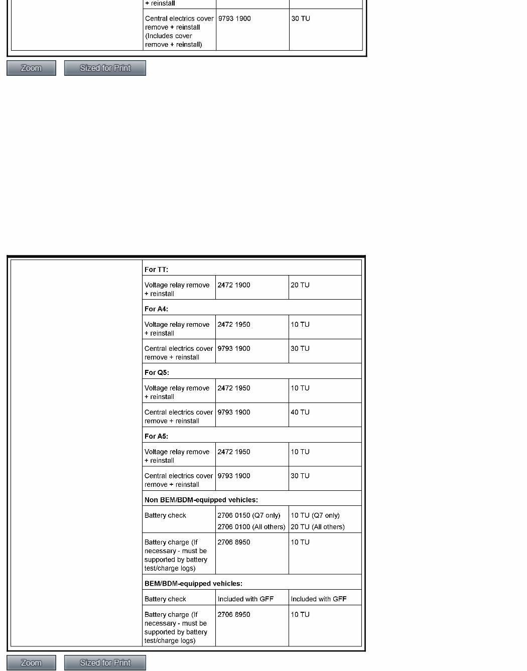
10. Check for battery voltage on J271 relay harness terminals 1 (85 power) and 3 (30 power) (Figure 8 and Figure 9).
If no voltage is found, do not proceed with this bulletin. Continue with diagnosis.11. With the ECM disconnected, check the wiring from J271 relay terminal 2 to the ECM:
^ If voltage and wiring are good, replace the J271 relay.
^ If voltage and wiring are not good, do not proceed with this bulletin. Continue with diagnosis. Note: Only use a DVOM whentaking measurements. If a non-approved device is used to check terminal 2, it can damage the ECM.
12. After replacing the J271 relay, reinstall the ECM and confirm that the vehicle can be started. If vehicle cannot be started,
continue with diagnosis.
13. Reinstall all components.
14. Check vehicle battery. Charge battery as needed before returning to customer.
15. Clear fault memory via ODIS GFF. Send diagnostic log via GFF Paperless.
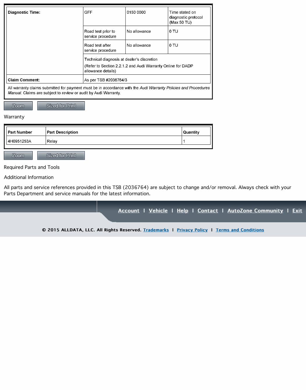
Warranty
Required Parts and Tools
Additional Information
All parts and service references provided in this TSB (2036764) are subject to change and/or removal. Always check with yourParts Department and service manuals for the latest information.
AccountAccount | | VehicleVehicle | | HelpHelp | | ContactContact | | AutoZone CommunityAutoZone Community | | ExitExit
© 2015 ALLDATA, LLC. Al l Rights Reserved. © 2015 ALLDATA, LLC. Al l Rights Reserved. TrademarksTrademarks | | Pr ivacy Pol icyPrivacy Pol icy | | Terms and Condit ionsTerms and Condit ions