your steering column specialist - ididit | custom … the input shaft of the gearbox or rack from...
TRANSCRIPT
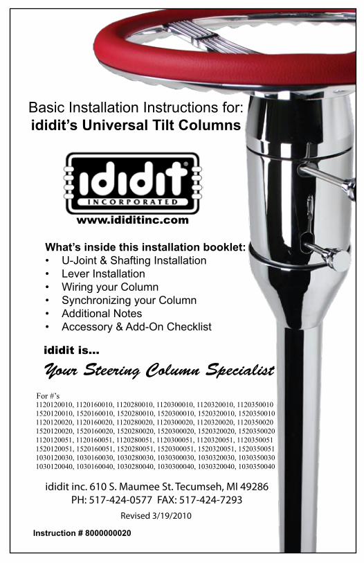
Basic Installation Instructions for ididitrsquos Universal Tilt Columns
ididit inc 610 S Maumee St Tecumseh MI 49286PH 517-424-0577 FAX 517-424-7293
wwwididitinccom
Revised 3192010
Instruction 8000000020
Whatrsquos inside this installation bookletU-Joint amp Shafting InstallationbullLever InstallationbullWiring your ColumnbullSynchronizing your ColumnbullAdditional NotesbullAccessory amp Add-On Checklistbull
ididit is
Your Steering Column Specialist
1120120010 1120160010 1120280010 1120300010 1120320010 11203500101520120010 1520160010 1520280010 1520300010 1520320010 15203500101120120020 1120160020 1120280020 1120300020 1120320020 11203500201520120020 1520160020 1520280020 1520300020 1520320020 15203500201120120051 1120160051 1120280051 1120300051 1120320051 11203500511520120051 1520160051 1520280051 1520300051 1520320051 15203500511030120030 1030160030 1030280030 1030300030 1030320030 10303500301030120040 1030160040 1030280040 1030300040 1030320040 1030350040
For rsquos
We will first give you an overview of mounting the steering column in the most common street rod or hot rod applications The steering column must be supported at the dash and where it protrudes through the firewall It is impor-tant that the steering column is tight and secure There is a shorty application which will use two drops under the dash with the support bearing through the firewall (since the column ends under the dash) To attach your column to the steering gear box a u-joint is attached to the column a shaft is attached to the u-joint and that shaft will lead down to a u-joint con-nected to the gear box (or rack)
It is highly recommended that you test fit your steering column before painting the column Test fitting now will save you a head-ache later on We are not responsible for paint
U-Joint InstallationFor proper installation of u-joints and couplers on your column follow manu-facturers recommendations but in general two basic styles used on your ididit inc steering column
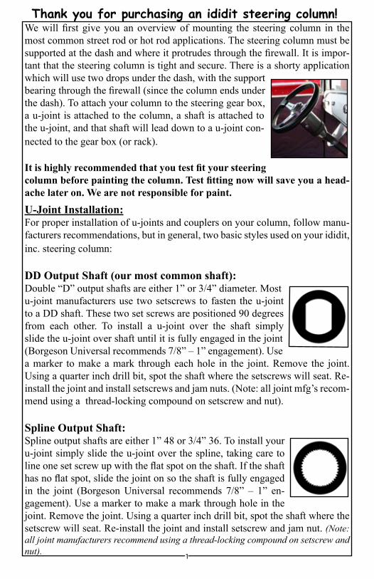
DD Output Shaft (our most common shaft)Double ldquoDrdquo output shafts are either 1rdquo or 34rdquo diameter Most u-joint manufacturers use two setscrews to fasten the u-joint to a DD shaft These two set screws are positioned 90 degrees from each other To install a u-joint over the shaft simply slide the u-joint over shaft until it is fully engaged in the joint (Borgeson Universal recommends 78rdquo ndash 1rdquo engagement) Use a marker to make a mark through each hole in the joint Remove the joint Using a quarter inch drill bit spot the shaft where the setscrews will seat Re-install the joint and install setscrews and jam nuts (Note all joint mfgrsquos recom-mend using a thread-locking compound on setscrew and nut)
Spline Output ShaftSpline output shafts are either 1rdquo 48 or 34rdquo 36 To install your u-joint simply slide the u-joint over the spline taking care to line one set screw up with the flat spot on the shaft If the shaft has no flat spot slide the joint on so the shaft is fully engaged in the joint (Borgeson Universal recommends 78rdquo ndash 1rdquo en-gagement) Use a marker to make a mark through hole in the joint Remove the joint Using a quarter inch drill bit spot the shaft where the setscrew will seat Re-install the joint and install setscrew and jam nut (Note all joint manufacturers recommend using a thread-locking compound on setscrew and nut) 1
Thank you for purchasing an ididit steering column
How to install your Tilt Turn Signal Levers and Hazard KnobTurn Signal LeverThe signal lever is the lever closest to the top of the column With the steering wheel and adaptor removed look down from the top of the column and yoursquoll see where a single screw holds the signal lever in place Insert the new lever using the provided screw into round hole (not D shaped hole) When installing this lever in a new column use the screw supplied to fasten the lever in the recessed area on the signal switch arm
Tilt LeverLook directly below the turn signal lever and yoursquoll see another opening in the column Inside this opening is a threaded hole which the new lever screws into
Emergency Flasher KnobAlmost directly opposite the turn lever on the steer-ing column is another opening Inside this open-ing is a hole in the nylon switch Simply screw the new knob in place (clockwise) When completing installation of flasher knob make sure that the knob is in the out (off) position so when finished wiring you donrsquot have any complications
If Column Shift ApplicationPlace column shift knob onto the shift lever Once your lever is on use setscrew (provided) and adjust knob so set screw is not facing for-ward tighten setscrew Do not remove the up-per shift lever for any reason The tension spring will pop out and it is very difficult to re-install
2
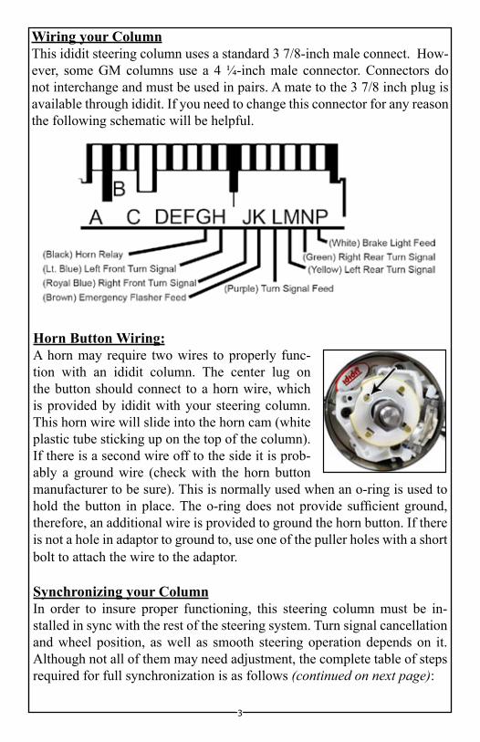
Wiring your ColumnThis ididit steering column uses a standard 3 78-inch male connect How-ever some GM columns use a 4 frac14-inch male connector Connectors do not interchange and must be used in pairs A mate to the 3 78 inch plug is available through ididit If you need to change this connector for any reason the following schematic will be helpful
Horn Button WiringA horn may require two wires to properly func-tion with an ididit column The center lug on the button should connect to a horn wire which is provided by ididit with your steering column This horn wire will slide into the horn cam (white plastic tube sticking up on the top of the column) If there is a second wire off to the side it is prob-ably a ground wire (check with the horn button manufacturer to be sure) This is normally used when an o-ring is used to hold the button in place The o-ring does not provide sufficient ground therefore an additional wire is provided to ground the horn button If there is not a hole in adaptor to ground to use one of the puller holes with a short bolt to attach the wire to the adaptor
Synchronizing your ColumnIn order to insure proper functioning this steering column must be in-stalled in sync with the rest of the steering system Turn signal cancellation and wheel position as well as smooth steering operation depends on it Although not all of them may need adjustment the complete table of steps required for full synchronization is as follows (continued on next page)
3
The front wheels must be pointing straight forward with the steering 1 toe set reasonably closeRotate the input shaft of the gearbox or rack from lock to lock and set 2 the box exactly half way between For example if the shaft rotates three full turns from lock to lock The center will be at 1frac12 turns from either locked positionInstall the steering arm and drag link and adjust tie rod ends to get the 3 drag link to fit without moving either the boxrack or the front wheels Rotating each tie rod end the same number of turns will preserve ad-justmentWith the column mounted in posi-4 tion and two joints are used on a shaft the forks of the yokes clos-est to each other should be in line or ldquoin phaserdquo Premature wear or binding can result if the u-joints are not phased properly Some-times if the u-joints are at a severe angle even if they are phased cor-rectly a hard spot in the steering may occur for no apparent reason If this happens index the u-joints two or three splines in one direction The hard spot should disappear or be minimizedInstall the shaft or joint on the gear boxrack Leave the upper part of 5 the shaft unconnected for the time beingPosition the column housing so that the signal switch arm is level to 6 the left hand sideInstall the column through firewall into your joint7 To achieve proper synchronizing of your column the finished instal-8 lation of your column should look like the col-umn diagram below If post on horn cam is not at 1030 grasp post and turn it until it is at 1030 Once completed your column now is in sync
4
IMPORTANT
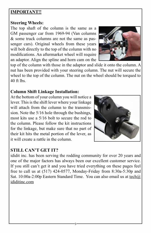
Steering WheelsThe top shaft of the column is the same as a GM passenger car from 1969-94 (Van columns amp some truck columns are not the same as pas-senger cars) Original wheels from these years will bolt directly to the top of the column with no modifications An aftermarket wheel will require an adaptor Align the spline and horn cam on the top of the column with those in the adaptor and slide it onto the column A nut has been provided with your steering column The nut will secure the wheel to the top of the column The nut on the wheel should be torqued to 40 ft lbs
Column Shift Linkage InstallationAt the bottom of your column you will notice a lever This is the shift lever where your linkage will attach from the column to the transmis-sion Note the 516 hole through the bushings most kits use a 516 bolt to secure the rod to the column Please follow the kit instructions for the linkage but make sure that no part of their kit hits the metal portion of the lever as it will create a rattle in the column
STILL CANrsquoT GET ITididit inc has been serving the rodding community for over 20 years and one of the major factors has always been our excellent customer service If you still canrsquot get it and you have tried everything on these pages feel free to call us at (517) 424-0577 Monday-Friday from 830a-530p and Sat 1000a-200p Eastern Standard Time You can also email us at techididitinccom
5
Think you may have forgotten something Herersquos what you may have missed
Add Ons (Add Ons should be installed on the column prior to shipment)1048576Cruise Control Carbureted Engine or Fuel Injected Engine
1048576Dimmer or Wiper DimmerWiper Kits will replace the original knobs and levers that come standard on an ididit column This is a replacement lever with a push but-ton at the end of the knob The DimmerWiper kit when pushed is either On or Off Includes relay kit
Accessories1048576Steering Wheel We cannot recommend any brand of wheel because there are so many to choose from If you are having a hard time figuring out if a wheel you had purchased will work with an adaptor or an ididit column simply give us a call
1048576Steering Wheel Adaptor Unless using original 1969 amp Up Steering Wheel you will need an adaptor The adaptor may depend on the wheel ididit recommends pur-chasing the Steering Wheel prior to purchasing the adaptor 3 5 6 or 9-Bolt Adaptors are Available with finishes of Chrome Black Powder Coated Brushed or Polished Aluminum The adaptors are available with or without Horn Buttons
1048576Under dash Mount (AKA Column Drop) A solid under dash mount is very nec-essary when installing your steering column ididit offers several variations of under dash mounts for Floor Shift amp Column Shift Columns When measuring for your column drop measure from the center of the column to the dash (see diagram)
1048576 Floor Mount Like the under dash mount this piece is very necessary when install-ing your steering column safely ididit offers a Classic Floor Mount Swivel Ball Floor Mount Adjustable Floor Mount with or without a trim piece Available for any ididit Steering Column
1048576 Shift Indicator Shift indicators available are 3 or 4-speed transmissions ididit also carries shift indicators for Ford AOD amp AODE transmissions The indicators are acrylic and can be ordered with or without the housing The housing finishes include Chrome Black Powder Coated Brushed or Polished Aluminum
1048576 Accessory Knobs for Levers or Dash Deco or Retro knobs are available to re-place the standard knobs that come standard on the column or if you plan on matching those knobs to your dash knobs Deco knobs are only available in Polished Aluminum Standard and Retro Knobs are available in Chrome Black Powder Coated Brushed or Polished Aluminum
1048576 Cable Shift Linkage Kit Kits are available for Ford C-4 C-6 amp AOD GM Trans-mission (350 400 700R4 200R4 4L60 amp 4L80) and Chrysler 727 amp 904 Transmis-sions Early power glide kits are not available however later power glide kits are
6
ididit inc610 S Maumee St Tecumseh MI 49286
(517) 424-0577 bull (517) 424-7293 fax
wwwididitinccom
No part of this guide may be reprinted reproduced or utilized in any form without the express written permission of ididit inc
2009 ididit incAll Rights ReservedPrinted in the USA
We will first give you an overview of mounting the steering column in the most common street rod or hot rod applications The steering column must be supported at the dash and where it protrudes through the firewall It is impor-tant that the steering column is tight and secure There is a shorty application which will use two drops under the dash with the support bearing through the firewall (since the column ends under the dash) To attach your column to the steering gear box a u-joint is attached to the column a shaft is attached to the u-joint and that shaft will lead down to a u-joint con-nected to the gear box (or rack)
It is highly recommended that you test fit your steering column before painting the column Test fitting now will save you a head-ache later on We are not responsible for paint
U-Joint InstallationFor proper installation of u-joints and couplers on your column follow manu-facturers recommendations but in general two basic styles used on your ididit inc steering column
DD Output Shaft (our most common shaft)Double ldquoDrdquo output shafts are either 1rdquo or 34rdquo diameter Most u-joint manufacturers use two setscrews to fasten the u-joint to a DD shaft These two set screws are positioned 90 degrees from each other To install a u-joint over the shaft simply slide the u-joint over shaft until it is fully engaged in the joint (Borgeson Universal recommends 78rdquo ndash 1rdquo engagement) Use a marker to make a mark through each hole in the joint Remove the joint Using a quarter inch drill bit spot the shaft where the setscrews will seat Re-install the joint and install setscrews and jam nuts (Note all joint mfgrsquos recom-mend using a thread-locking compound on setscrew and nut)
Spline Output ShaftSpline output shafts are either 1rdquo 48 or 34rdquo 36 To install your u-joint simply slide the u-joint over the spline taking care to line one set screw up with the flat spot on the shaft If the shaft has no flat spot slide the joint on so the shaft is fully engaged in the joint (Borgeson Universal recommends 78rdquo ndash 1rdquo en-gagement) Use a marker to make a mark through hole in the joint Remove the joint Using a quarter inch drill bit spot the shaft where the setscrew will seat Re-install the joint and install setscrew and jam nut (Note all joint manufacturers recommend using a thread-locking compound on setscrew and nut) 1
Thank you for purchasing an ididit steering column
How to install your Tilt Turn Signal Levers and Hazard KnobTurn Signal LeverThe signal lever is the lever closest to the top of the column With the steering wheel and adaptor removed look down from the top of the column and yoursquoll see where a single screw holds the signal lever in place Insert the new lever using the provided screw into round hole (not D shaped hole) When installing this lever in a new column use the screw supplied to fasten the lever in the recessed area on the signal switch arm
Tilt LeverLook directly below the turn signal lever and yoursquoll see another opening in the column Inside this opening is a threaded hole which the new lever screws into
Emergency Flasher KnobAlmost directly opposite the turn lever on the steer-ing column is another opening Inside this open-ing is a hole in the nylon switch Simply screw the new knob in place (clockwise) When completing installation of flasher knob make sure that the knob is in the out (off) position so when finished wiring you donrsquot have any complications
If Column Shift ApplicationPlace column shift knob onto the shift lever Once your lever is on use setscrew (provided) and adjust knob so set screw is not facing for-ward tighten setscrew Do not remove the up-per shift lever for any reason The tension spring will pop out and it is very difficult to re-install
2
Wiring your ColumnThis ididit steering column uses a standard 3 78-inch male connect How-ever some GM columns use a 4 frac14-inch male connector Connectors do not interchange and must be used in pairs A mate to the 3 78 inch plug is available through ididit If you need to change this connector for any reason the following schematic will be helpful
Horn Button WiringA horn may require two wires to properly func-tion with an ididit column The center lug on the button should connect to a horn wire which is provided by ididit with your steering column This horn wire will slide into the horn cam (white plastic tube sticking up on the top of the column) If there is a second wire off to the side it is prob-ably a ground wire (check with the horn button manufacturer to be sure) This is normally used when an o-ring is used to hold the button in place The o-ring does not provide sufficient ground therefore an additional wire is provided to ground the horn button If there is not a hole in adaptor to ground to use one of the puller holes with a short bolt to attach the wire to the adaptor
Synchronizing your ColumnIn order to insure proper functioning this steering column must be in-stalled in sync with the rest of the steering system Turn signal cancellation and wheel position as well as smooth steering operation depends on it Although not all of them may need adjustment the complete table of steps required for full synchronization is as follows (continued on next page)
3
The front wheels must be pointing straight forward with the steering 1 toe set reasonably closeRotate the input shaft of the gearbox or rack from lock to lock and set 2 the box exactly half way between For example if the shaft rotates three full turns from lock to lock The center will be at 1frac12 turns from either locked positionInstall the steering arm and drag link and adjust tie rod ends to get the 3 drag link to fit without moving either the boxrack or the front wheels Rotating each tie rod end the same number of turns will preserve ad-justmentWith the column mounted in posi-4 tion and two joints are used on a shaft the forks of the yokes clos-est to each other should be in line or ldquoin phaserdquo Premature wear or binding can result if the u-joints are not phased properly Some-times if the u-joints are at a severe angle even if they are phased cor-rectly a hard spot in the steering may occur for no apparent reason If this happens index the u-joints two or three splines in one direction The hard spot should disappear or be minimizedInstall the shaft or joint on the gear boxrack Leave the upper part of 5 the shaft unconnected for the time beingPosition the column housing so that the signal switch arm is level to 6 the left hand sideInstall the column through firewall into your joint7 To achieve proper synchronizing of your column the finished instal-8 lation of your column should look like the col-umn diagram below If post on horn cam is not at 1030 grasp post and turn it until it is at 1030 Once completed your column now is in sync
4
IMPORTANT
Steering WheelsThe top shaft of the column is the same as a GM passenger car from 1969-94 (Van columns amp some truck columns are not the same as pas-senger cars) Original wheels from these years will bolt directly to the top of the column with no modifications An aftermarket wheel will require an adaptor Align the spline and horn cam on the top of the column with those in the adaptor and slide it onto the column A nut has been provided with your steering column The nut will secure the wheel to the top of the column The nut on the wheel should be torqued to 40 ft lbs
Column Shift Linkage InstallationAt the bottom of your column you will notice a lever This is the shift lever where your linkage will attach from the column to the transmis-sion Note the 516 hole through the bushings most kits use a 516 bolt to secure the rod to the column Please follow the kit instructions for the linkage but make sure that no part of their kit hits the metal portion of the lever as it will create a rattle in the column
STILL CANrsquoT GET ITididit inc has been serving the rodding community for over 20 years and one of the major factors has always been our excellent customer service If you still canrsquot get it and you have tried everything on these pages feel free to call us at (517) 424-0577 Monday-Friday from 830a-530p and Sat 1000a-200p Eastern Standard Time You can also email us at techididitinccom
5
Think you may have forgotten something Herersquos what you may have missed
Add Ons (Add Ons should be installed on the column prior to shipment)1048576Cruise Control Carbureted Engine or Fuel Injected Engine
1048576Dimmer or Wiper DimmerWiper Kits will replace the original knobs and levers that come standard on an ididit column This is a replacement lever with a push but-ton at the end of the knob The DimmerWiper kit when pushed is either On or Off Includes relay kit
Accessories1048576Steering Wheel We cannot recommend any brand of wheel because there are so many to choose from If you are having a hard time figuring out if a wheel you had purchased will work with an adaptor or an ididit column simply give us a call
1048576Steering Wheel Adaptor Unless using original 1969 amp Up Steering Wheel you will need an adaptor The adaptor may depend on the wheel ididit recommends pur-chasing the Steering Wheel prior to purchasing the adaptor 3 5 6 or 9-Bolt Adaptors are Available with finishes of Chrome Black Powder Coated Brushed or Polished Aluminum The adaptors are available with or without Horn Buttons
1048576Under dash Mount (AKA Column Drop) A solid under dash mount is very nec-essary when installing your steering column ididit offers several variations of under dash mounts for Floor Shift amp Column Shift Columns When measuring for your column drop measure from the center of the column to the dash (see diagram)
1048576 Floor Mount Like the under dash mount this piece is very necessary when install-ing your steering column safely ididit offers a Classic Floor Mount Swivel Ball Floor Mount Adjustable Floor Mount with or without a trim piece Available for any ididit Steering Column
1048576 Shift Indicator Shift indicators available are 3 or 4-speed transmissions ididit also carries shift indicators for Ford AOD amp AODE transmissions The indicators are acrylic and can be ordered with or without the housing The housing finishes include Chrome Black Powder Coated Brushed or Polished Aluminum
1048576 Accessory Knobs for Levers or Dash Deco or Retro knobs are available to re-place the standard knobs that come standard on the column or if you plan on matching those knobs to your dash knobs Deco knobs are only available in Polished Aluminum Standard and Retro Knobs are available in Chrome Black Powder Coated Brushed or Polished Aluminum
1048576 Cable Shift Linkage Kit Kits are available for Ford C-4 C-6 amp AOD GM Trans-mission (350 400 700R4 200R4 4L60 amp 4L80) and Chrysler 727 amp 904 Transmis-sions Early power glide kits are not available however later power glide kits are
6
ididit inc610 S Maumee St Tecumseh MI 49286
(517) 424-0577 bull (517) 424-7293 fax
wwwididitinccom
No part of this guide may be reprinted reproduced or utilized in any form without the express written permission of ididit inc
2009 ididit incAll Rights ReservedPrinted in the USA

ididit inc610 S Maumee St Tecumseh MI 49286
(517) 424-0577 bull (517) 424-7293 fax
wwwididitinccom
No part of this guide may be reprinted reproduced or utilized in any form without the express written permission of ididit inc
2009 ididit incAll Rights ReservedPrinted in the USA
