you may not start to read the questions printed on the...
TRANSCRIPT

Version WON/4
Page 1 of 28
MET2 MANUFACTURING ENGINEERING TRIPOS PART IIA ______________________________________________________________________ Monday 25 April 2016 9 to 10.30 ______________________________________________________________________ Paper 2
Module 3P2: OPERATION AND CONTROL OF PRODUCTION MACHINES AND SYSTEMS
Answer two questions, one from each of sections A and B. Answers to sections A and B must appear in two separate booklets. All questions carry the same number of marks. The approximate percentage of marks allocated to each part of a question is
indicated in the right margin. Write your candidate number not your name on the cover sheet.
STATIONERY REQUIREMENTS 8 page answer booklet x 2 Rough work pad SPECIAL REQUIREMENTS TO BE SUPPLIED FOR THIS EXAM CUED approved calculator allowed Engineering Data Book
10 minutes reading time is allowed for this paper.
You may not start to read the questions printed on the subsequent pages of this question paper until instructed to do so.
Version WON/4
Page 2 of 28
SECTION A
Answer one question from this section.
1 (a) Describe the four main categories of chip formation produced in orthogonal cutting. In each case, list the general machining conditions that lead to their production. [20%]
(b) Describe the main classifications of tool wear and discuss their causes. [20%]
(c) Sketch typical wear/time curves for a cutting tool from the initial point of use to the point of failure. Explain how this data can be used to define the characteristic of a particular cutting tool/component material combination. [20%]
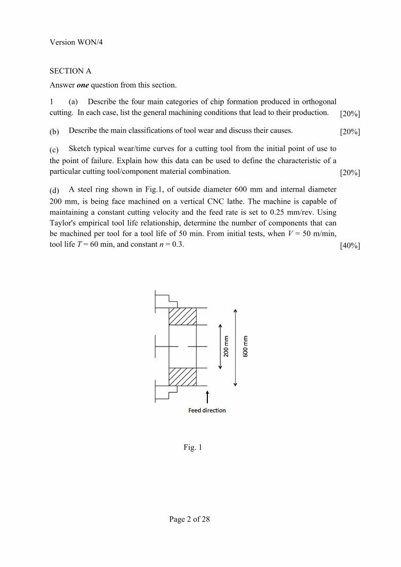
(d) A steel ring shown in Fig.1, of outside diameter 600 mm and internal diameter 200 mm, is being face machined on a vertical CNC lathe. The machine is capable of maintaining a constant cutting velocity and the feed rate is set to 0.25 mm/rev. Using Taylor's empirical tool life relationship, determine the number of components that can be machined per tool for a tool life of 50 min. From initial tests, when V = 50 m/min, tool life T = 60 min, and constant n = 0.3. [40%]
Fig. 1

Version WON/4
Page 3 of 28 (TURN OVER
Question-1 CRIB
a) Four main types:
• Continuous
Continuous chips are formed by the continuous plastic deformation of metal without
fracture in front of the cutting edge of the tool, with a smooth flow of the chip up
the tool face. Formed under the following conditions:
i) Formed with ductile materials ii) Machined at high cutting speeds iii) Machined at high rake angles iv) Machined at small feeds v) Low tool/chip friction
• Built-up edge
This type of chip is very similar to the continuous chip. With the difference that it
has a built up edge adjacent to tool face. Consists of layers of material from the
workpiece that are deposited on the tool tip. As it grows larger, the BUE becomes
unstable and eventually breaks apart.
Formed under the following conditions:
i) Ductile materials ii) Low to medium cutting speeds iii) High tool/chip friction (wrong tool material) iv) Low levels of cutting fluid
• Serrated or segmented
Version WON/4
Version 5 (cont.
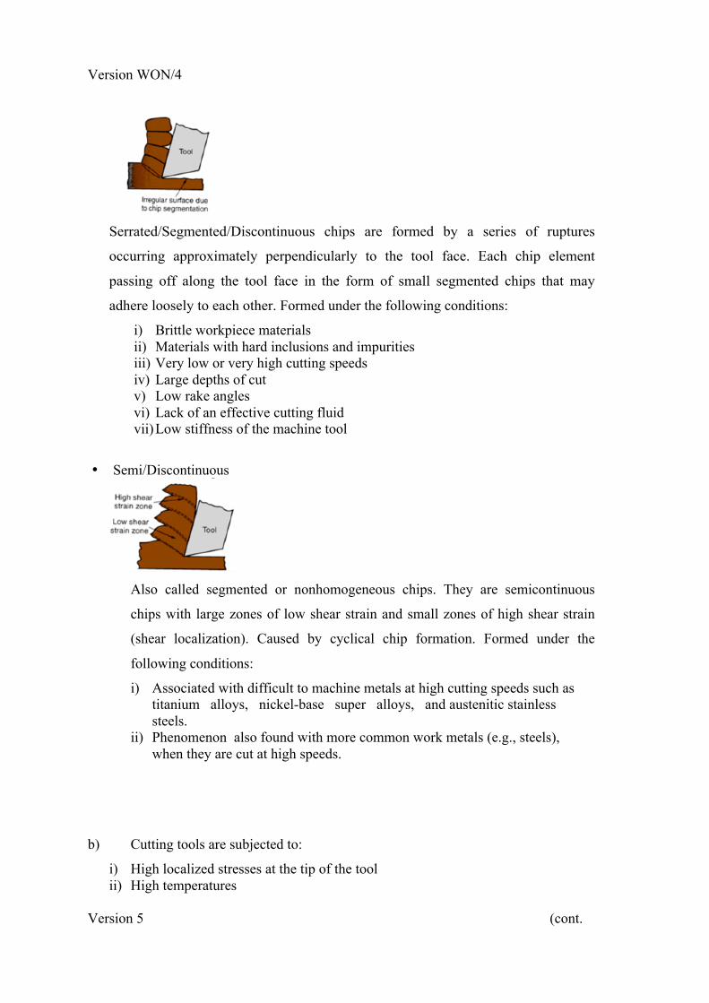
Serrated/Segmented/Discontinuous chips are formed by a series of ruptures
occurring approximately perpendicularly to the tool face. Each chip element
passing off along the tool face in the form of small segmented chips that may
adhere loosely to each other. Formed under the following conditions:
i) Brittle workpiece materials ii) Materials with hard inclusions and impurities iii) Very low or very high cutting speeds iv) Large depths of cut v) Low rake angles vi) Lack of an effective cutting fluid vii) Low stiffness of the machine tool
• Semi/Discontinuous
Also called segmented or nonhomogeneous chips. They are semicontinuous
chips with large zones of low shear strain and small zones of high shear strain
(shear localization). Caused by cyclical chip formation. Formed under the
following conditions:
i) Associated with difficult to machine metals at high cutting speeds such as titanium alloys, nickel-base super alloys, and austenitic stainless steels.
ii) Phenomenon also found with more common work metals (e.g., steels), when they are cut at high speeds.
b) Cutting tools are subjected to:
i) High localized stresses at the tip of the tool ii) High temperatures
Version WON/4
Page 5 of 28 (TURN OVER
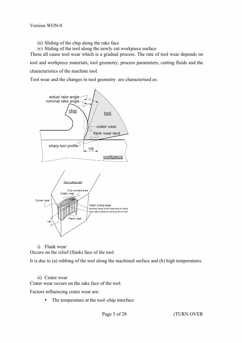
iii) Sliding of the chip along the rake face iv) Sliding of the tool along the newly cut workpiece surface
These all cause tool wear which is a gradual process. The rate of tool wear depends on
tool and workpiece materials, tool geometry, process parameters, cutting fluids and the
characteristics of the machine tool.
Tool wear and the changes in tool geometry are characterised as:
i) Flank wear
Occurs on the relief (flank) face of the tool
It is due to (a) rubbing of the tool along the machined surface and (b) high temperatures
ii) Crater wear Crater wear occurs on the rake face of the tool.
Factors influencing crater wear are:
• The temperature at the tool–chip interface

Version WON/4
Version 5 (cont.
• The chemical affinity between the tool and workpiece materials • Diffusion rate increases with increasing temperature, crater wear increases as
temperature increases • Location of the max depth of crater wear, KT, coincides with the location of
the max temperature at the tool–chip interface
iii) Corner (nose) wear Corner wear is the rounding of a sharp tool due to mechanical and thermal effects. It
dulls the tool, affects chip formation and causes rubbing of the tool over the workpiece.
iv) Notching plastic deformation of the tool tip Tools also may undergo plastic deformation because of temperature rises in the cutting
zone.
v) Chipping Tools may undergo chipping, where small fragment from the cutting edge of the tool
breaks away. Chipping may occur in a region of the tool where a small crack already
exists. Two main causes of chipping: Mechanical shock & Thermal fatigue
vi) Gross fracture Tools may exhibit gross fracture (catastrophic failure) when subject to extreme
conditions and excessive wear.
Version WON/4
Page 7 of 28 (TURN OVER
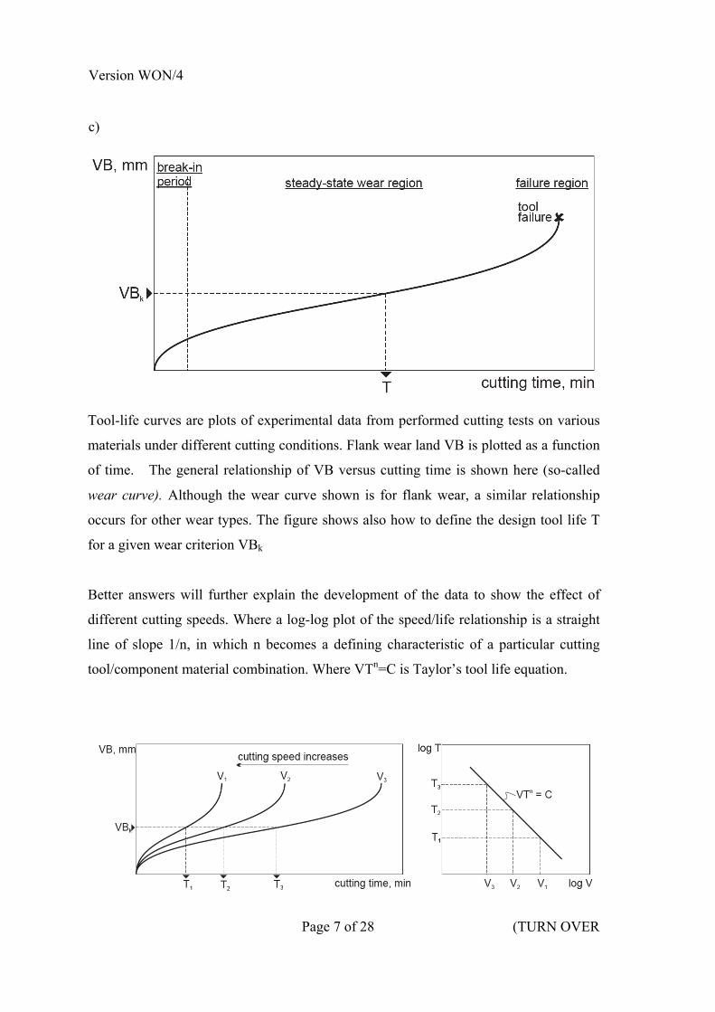
c)
Tool-life curves are plots of experimental data from performed cutting tests on various
materials under different cutting conditions. Flank wear land VB is plotted as a function
of time. The general relationship of VB versus cutting time is shown here (so-called
wear curve). Although the wear curve shown is for flank wear, a similar relationship
occurs for other wear types. The figure shows also how to define the design tool life T
for a given wear criterion VBk
Better answers will further explain the development of the data to show the effect of
different cutting speeds. Where a log-log plot of the speed/life relationship is a straight
line of slope 1/n, in which n becomes a defining characteristic of a particular cutting
tool/component material combination. Where VTn=C is Taylor’s tool life equation.

Version WON/4
Version 5 (cont.
d) Given V = 50 [m/min]; T = 60 [min] and n = 0.3 and using Taylor’s relationship
V.Tn = C, we can calculate
C = 50. 60(0.3) = lg50 + 0.3 lg60 = lgC or
lg C = 1.69 + 0.3 . 1.778 = 2.23
C = 170.77
From figure.1 we calculate
€
φ600 −φ2002
=D − d2
⎛
⎝ ⎜
⎞
⎠ ⎟ = 200mm = S
At a feed rate of t = 0.25 mm/rev we will need:
€
€
n1 =St
revolutions of the spindle (workpiece) to be able to machine the face of the ring, giving
€
n1 =St
=2000.25
= 800[rev]
Since according to the initial assignment, the cutting speed is constant Vc= const, then
from Taylor’s equation
V.Tn = C and for T = 50 [min] we have
V.50 0.3 = 170.77148
V= 52.81 m/min
The tool path length between φ 600 mm and φ 200 mm is
€
S1 = π D − d( )n13.14(600 − 200).800 =1004.8[m]

Version WON/4
Page 9 of 28 (TURN OVER
Note to examiner: there are of course other methods to calculate the same length: i.e
finite sum; polar equation, or area method, where
€
S1t =π4⎛
⎝ ⎜
⎞
⎠ ⎟ D2 − d2( )
S1 = 3.412(360,000 − 40,000) =1005.44[m]
The time T1 required for a single workpiece to be machined by the tool is
€
T1 =S1V
=1004.852.81
=19.0266min
The number of components that can be machined is
€
N =TT1
=5019.02
N = 2.62 components Examiners Comments The most popular question, answered very well by some, reasonably well by others. Good understanding of chip formation was shown in addition to the machining conditions that lead to the various forms. High scoring candidates were able to give comprehensive lists of the machining conditions for each chip type. Tool wear classifications were well understood by the majority of candidates, with good answers supported by clear diagrams. Taylor’s tool life curves were discussed comprehensively by high scoring answers, where cursory descriptions without diagrams scored poorly. A good proportion of the class successfully developed the tool life analysis, although some answers failed to correctly calculate the correct length of the face-cut in order to determine the number of components that could be machined for the given tool life. There was low level of detail in many answers in parts a), and b): candidates could often identify the categories, but failed to understand the key causes of chip formation or tool wear. The question was particularly difficult for those candidates that did not have a broad knowledge of machining.

Version WON/4
Page 10 of 28
2 (a) In studying the mechanics of orthogonal metal cutting, Merchant proposed a thin shear-plane cutting model. What assumptions did he base his model on? [10%]
(b) Using Merchant’s circle, derive the force equations for friction force F, normal force to the rake face N, shear force on shear plane Fs and normal force to the shear plane Fn as functions of cutting force Fc and thrust Force Ft. [30%] (c) Orthogonal cutting of steel is carried out with a rake angle οf 10 degrees. The cutting speed is 200 mm/min and the chip thickness ratio is 0.31. The thrust force Ft and the cutting force Fc are measured as 1200 N and 650 N respectively. Using this data,
(i) Determine the validity of the shear-angle relationship suggested by Merchant, which is given as
where φ is the shear angle, β is the friction angle, and α is the rake angle. [30%] (ii) What is the proportion of shear work to the total work done? [15%]
(iii) What is the proportion of friction work to the total work done? [15%]
Version WON/4
Page 11 of 28 (TURN OVER
Question 2 Crib
a)
Merchant’s assumptions were
1 The tool is perfectly sharp and has no contact along the clearance face 2 The surface of shear is occurring in a plane 3 The cutting edge is a straight line extending perpendicular to the direction of motion and generates a plan surface as the work moves past it 4 The chip does not flow to either side 5 Uncut chip thickness is constant 6 Width of the tool is greater than the width of the work 7 A continuous chip is produced without BUE 8 Work moves in a uniform velocity 9 The stresses on the shear plane are uniformly distributed from 10 Shear angle φ adjusts itself to minimise work
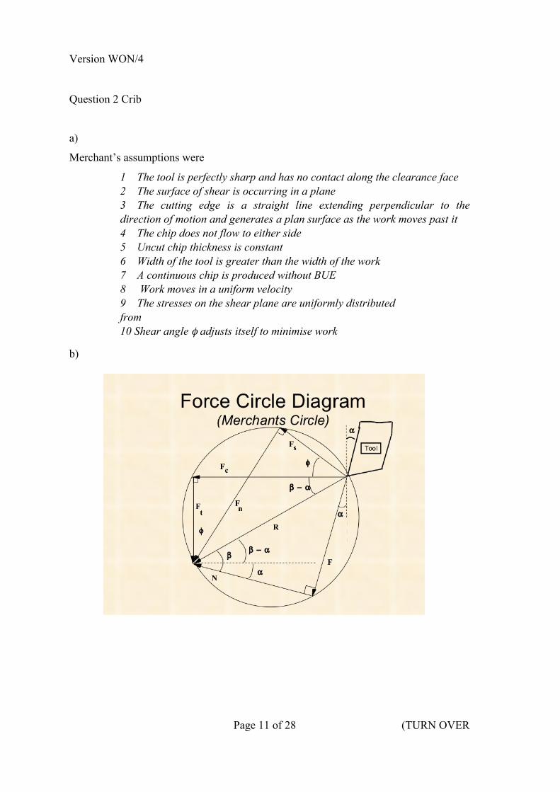
b)

Version WON/4
Page 12 of 28
From the force circle one can show through trigonometric relations that
F = Fc sin α + Ft cos α
N = Fc cos α - Ft sin α
Fs = Fc cos φ - Ft sin φ
Fn = Fc sin φ + Ft cos φ
To verify Merchant’s shear angle relationship, which predicts the shear angle from the
friction angle and rake angle, we must calculate the shear angle from known values, and
compare it with his predictions. To do this we must also calculate the friction angle.
First let us calculate the shear angle that is given as
€
tanφ =rcosα1− rsinα
=0.31cos101− 0.31sin10
Shear angle, φ = tan-1(0.32266) = 17.880
The coefficient of friction µ at the chip tool interface is given by
€
µ =FN
and the friction angle b is given by
€
β = tan−1µ
Therefore we must calculate F and N
Where F = Fc sin α + Ft cos α = 650 sin 10 + 1200 cos 10 = 1294.64 Ν
And N = Fc cos α - Ft sin α = 650 cos 10 − 1200 sin 10 = 431.75 Ν
The friction angle β is then given by
€
β = tan−1µ = tan−1 1294.64431.75
= 71.560
Applying this value to Merchant’s shear angle relationship gives

Version WON/4
Page 13 of 28 (TURN OVER
€
φ =π4−12β −α( ) =
π4−1271.56 −10( ) =14.220
This differs from the calculated value of 17.88, making the Merchant relationship some
20.5% in error.
Better answers will discuss the causes of violation of the model, i.e
• Geometry and form violations (non zero angles of inclination, non-sharp tools, radius ends)
• Shear takes place over a volume not a plane • Cutting is never continuous • Cracks in the material which is not homogenous • Size effect (larger stresses are required to produce deformation when the chip is
small)
iii) Shear work done is
Ws = FsVs
We must therefore calculate Vs and Fs
From Velocity diagram, we can obtain equations from trigonometric relationships
Version WON/4
Page 14 of 28
In which case gives
€
Vs =V cosα
Cos φ −α( )=3.3 ×10⁻³ cos10cos 17.88 −10( )
= 3.31×10⁻³m /s
and
Fs = Fc cos φ - Ft sin φ = 650 cos 17.88 -‐ 1200 sin 17.88 = 250.2 N
Which gives
Ws = FsVs = 250.2 x 3.31 x10-‐3 = 0.83 Nm/s
The total work done is
W = FcV = 650 x 3.33x10-‐3 = 2.165 Nm/s
Therefore the proportion of shear work to the total work done is
€
0.832.165
= 0.3833 (38.34%)
iii) The proportion of friction work done to the total work is simply the remainder, i.e.
61.66%, since Power input Fc.V = Shearing + friction.
Examiners Comments A well-answered question, with relatively few takers. Those that chose this question were confident in their knowledge and were not put off by its analytical nature. Few candidates were able to offer comprehensive discussion of the model assumptions. The force equations were developed with the use of the force circle, with come candidates choosing the graphical approach. The numerical analysis was attempted well. The validity of the shear angle was tested numerically by most, with few candidates choosing to expand on the reasons for its violation. Some candidates used their value of φ from the Merchant’s expression rather than the calculated value. Most marks were lost due to developing incorrect force terms, or lack of accuracy in the calculations.
Version WON/4
Page 15 of 28 (TURN OVER
SECTION B
Answer one question from this section.
3 (a) Industrial robots have been developed over many years to meet the needs of industrial applications. These developments have been in many areas including robot arm configurations, motion drive systems and on-board software systems.
(i) Discuss and compare the different approaches used for programming robots. [10%]
(ii) For three robot types with different degrees of freedom, discuss the influence that the robot’s degrees of freedom will have on potential applications. [20%]
(iii) Why are more flexible, ‘human-like’ robots becoming more popular in industrial robot developments? [20%]
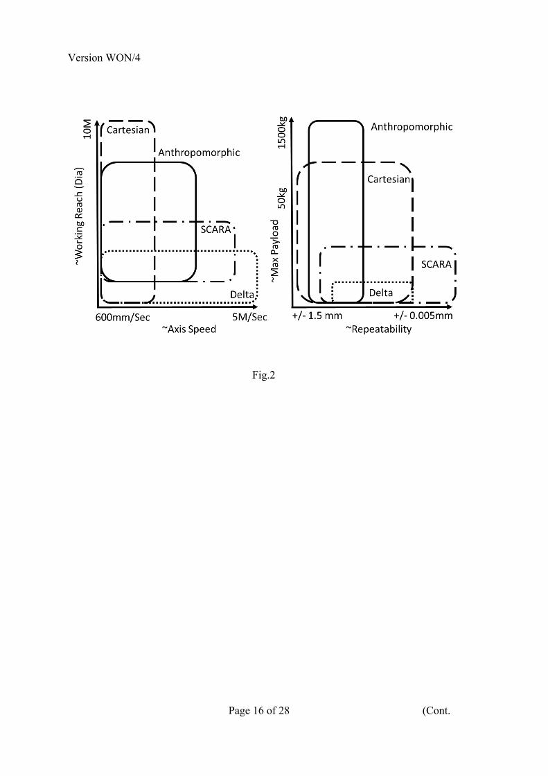
(b) A consumer electronics company is looking to purchase a robot to carry out packaging at the end of a washing machine production line. The robot is required to lift a 50 kg washing machine off the assembly line and place it into an open cardboard box on the pallet line. This will require a robot to have a reach of three meters and an axis speed of one meter per second. Fig. 2 gives a chart showing the characteristics of different types of robots. Examine the information given in Fig. 2 and determine the best type of robot for this task. Describe why you have chosen this type of robot, listing both the benefits and limitations that you have considered. What other information might you request to assist you in making your decision? [50%]
Version WON/4
Page 16 of 28 (Cont.
Fig.2

Version WON/4
Page 17 of 28 (TURN OVER
Q3 Crib
Answer
3ai) See table below
Techniques Pros Cons Usage
Teach Mode • Simple wide used technique.
• No additional infrastructure required during programming.
• Time consuming and repetitive.
• Limited automated testing and verification.
80%
Most Popular
(Assembly)
(Welding)
(Packaging)
Lead
Through
• Mimics complex trajectories used by skilled operators (Paint Sprayer).
• Difficult to deal with Large Robots.
• Inaccuracies in programmes can’t be edited.
Small %
Mainly Historic
(Paint
Spraying)
Off-Line • Reduced down time during in programming.
• Assists cell design and allows process optimisation.
• Requirement for accurate CAD models of instillation.
• Accuracy of robot is critical when using off-line programming techniques.
20%
Growing Usage
Used to verify
takt time.
(All Areas)
Version WON/4
Page 18 of 28 (Cont.
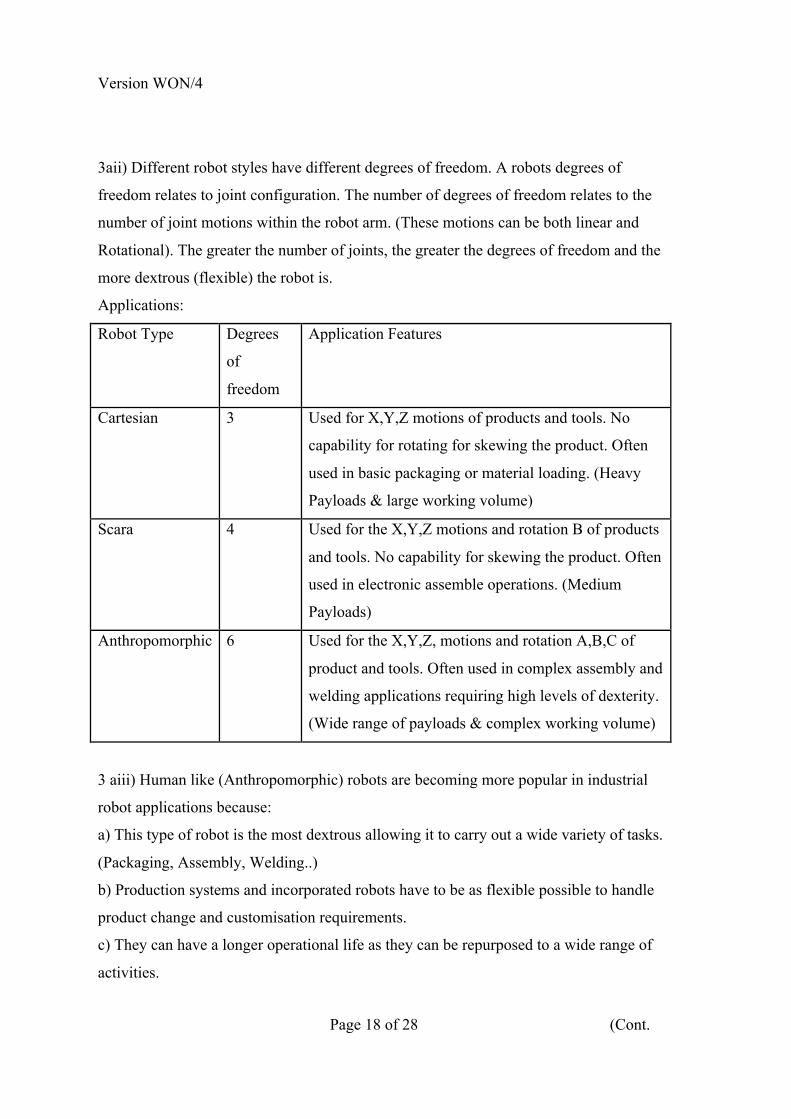
3aii) Different robot styles have different degrees of freedom. A robots degrees of
freedom relates to joint configuration. The number of degrees of freedom relates to the
number of joint motions within the robot arm. (These motions can be both linear and
Rotational). The greater the number of joints, the greater the degrees of freedom and the
more dextrous (flexible) the robot is.
Applications:
Robot Type Degrees
of
freedom
Application Features
Cartesian 3 Used for X,Y,Z motions of products and tools. No
capability for rotating for skewing the product. Often
used in basic packaging or material loading. (Heavy
Payloads & large working volume)
Scara 4 Used for the X,Y,Z motions and rotation B of products
and tools. No capability for skewing the product. Often
used in electronic assemble operations. (Medium
Payloads)
Anthropomorphic 6 Used for the X,Y,Z, motions and rotation A,B,C of
product and tools. Often used in complex assembly and
welding applications requiring high levels of dexterity.
(Wide range of payloads & complex working volume)
3 aiii) Human like (Anthropomorphic) robots are becoming more popular in industrial
robot applications because:
a) This type of robot is the most dextrous allowing it to carry out a wide variety of tasks.
(Packaging, Assembly, Welding..)
b) Production systems and incorporated robots have to be as flexible possible to handle
product change and customisation requirements.
c) They can have a longer operational life as they can be repurposed to a wide range of
activities.

Version WON/4
Page 19 of 28 (TURN OVER
3 bi) Characteristics:
Robot Reach 3M, Payload 50Kg, Axis Speed 1M/s for these characteristics two robot
types would be suitable for this task, Cartesian or Anthropomorphic. From the
information provided I would chose a Cartesian robot.
Robot Style Benefits Limitations
• Can handle heavy payloads • May have limited rotary axis for rotating or skewing the product.
• Has a big working volume • Can require high ceilings to cater for Z Axis in the up position.
• Good configuration for straddling equipment in the factory.
• Limited flexibility depending on wrist configuration.
• Typically is a lower cost robot
Cartesian
• Less complicated to programme
Other information that would be required to verify this decision.
a) Will the washing machine need to be rotated or skewed during the packing operation?
b) What space is available for the robot installation / Operation?
c) What repeatability will be required in the packing operation?
c) Will the robot be required to carry out any other tasks?
Examiners comments
The question was answered well with a good spread of marks across each section of the
question. The question tested candidate’s knowledge of the 3P2 material. It could be
seen from 3ai (Robot programming techniques) that candidates had the least clarity
about Off-Line programming. 3aii (General Robot Types DoF & Applications) was
answered well although candidates discussions on applications was limited. 3aiii. (The
use of “Human” like robots) again was answered well with a good number of candidates
adding additional knowledge of Collaborative robotics. 3b the majority of the
candidates identified that either a Cartesian or Anthropomorphic robot could be used for
the task specified. Extra credit was awarded for selecting a Cartesian robots due to its
lower cost and simplicity.

Version WON/4
Page 20 of 28 (Cont.
The largest differentiator in candidate’s answers was in discussions of benefits,
limitations
and additional information required for further system specification.
Version WON/4
Page 21 of 28 (TURN OVER
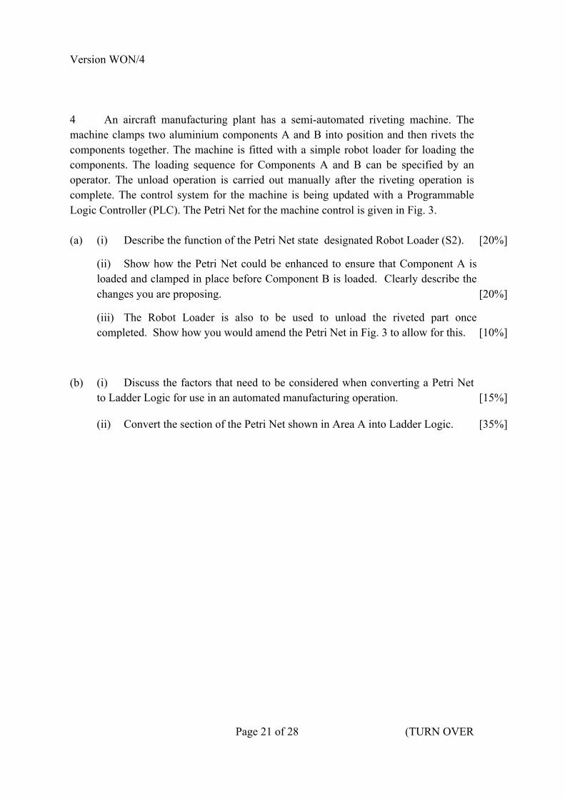
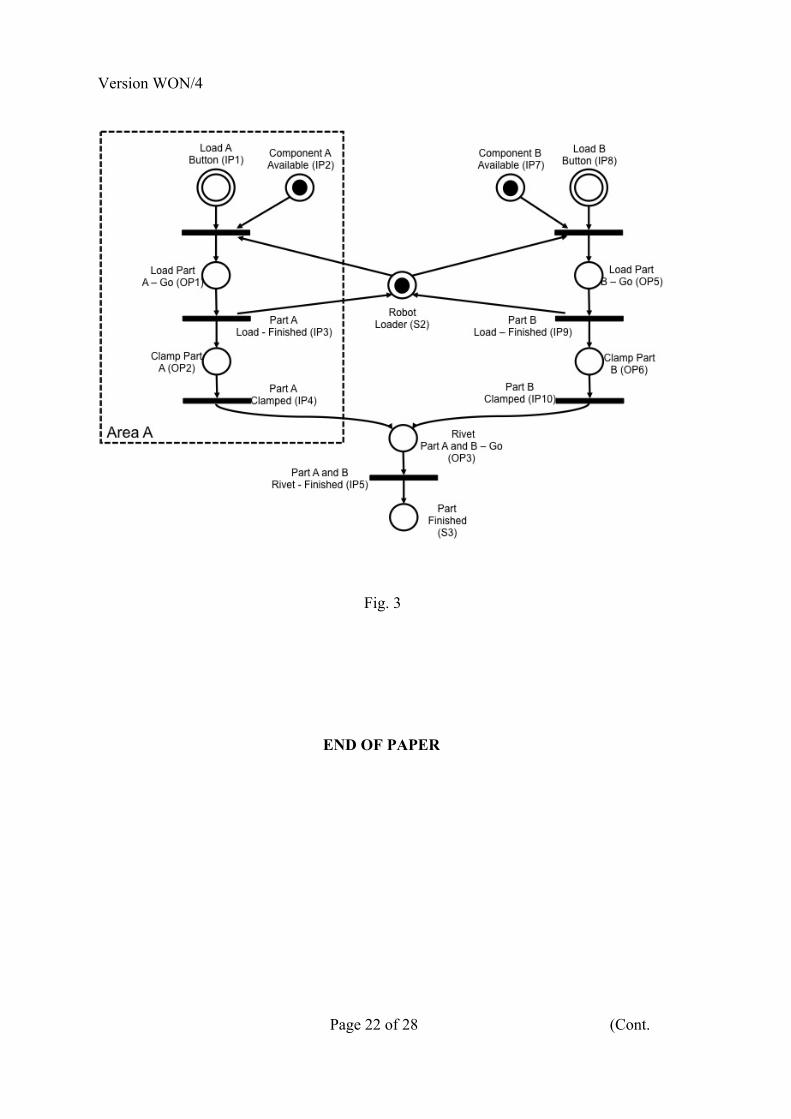
4 An aircraft manufacturing plant has a semi-automated riveting machine. The machine clamps two aluminium components A and B into position and then rivets the components together. The machine is fitted with a simple robot loader for loading the components. The loading sequence for Components A and B can be specified by an operator. The unload operation is carried out manually after the riveting operation is complete. The control system for the machine is being updated with a Programmable Logic Controller (PLC). The Petri Net for the machine control is given in Fig. 3. (a) (i) Describe the function of the Petri Net state designated Robot Loader (S2). [20%]
(ii) Show how the Petri Net could be enhanced to ensure that Component A is loaded and clamped in place before Component B is loaded. Clearly describe the changes you are proposing. [20%]
(iii) The Robot Loader is also to be used to unload the riveted part once completed. Show how you would amend the Petri Net in Fig. 3 to allow for this. [10%]
(b) (i) Discuss the factors that need to be considered when converting a Petri Net to Ladder Logic for use in an automated manufacturing operation. [15%]
(ii) Convert the section of the Petri Net shown in Area A into Ladder Logic. [35%]
Version WON/4
Page 22 of 28 (Cont.
Fig. 3
END OF PAPER
Version WON/4
Page 23 of 28 (TURN OVER
Q4 Crib
4 ai) The state (Robot Loader) has two functions, firstly it indicates that the robot loader
is free to undertake a task and secondly it ensures that both load cycles cannot be run
simultaneously.
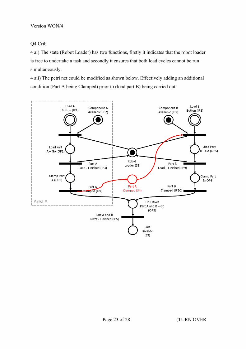
4 aii) The petri net could be modified as shown below. Effectively adding an additional
condition (Part A being Clamped) prior to (load part B) being carried out.

Version WON/4
Page 24 of 28 (Cont.
4 aiii) The petri net could be modified as shown below. Effectively adding additional
place to perform the unload operation as well as linking back to the initial places for
load operations. The Robot Loader place has also been linking into the unload operation
to eliminate resource contention between load and unload operations.
Version WON/4
Page 25 of 28 (TURN OVER
4 bi) The following considerations have to be made in converting a petri nets to ladder
logic.
a) Ensure that the logic within the petri net is correct and it provides the correct
functionality keeping in mind. (Start Conditions, Deadlocks, Conflicts, Suitability for
continues operations).
b) For each of the elements within the petri net, identify related variable conditions.
Transitions need to be mapped to specific external triggers [I/O Input’s and their states].
Places need to be mapped to PLC memory locations [associated variables]. Places also
need to be mapped to external actuation signals [I/O Output’s and their states].
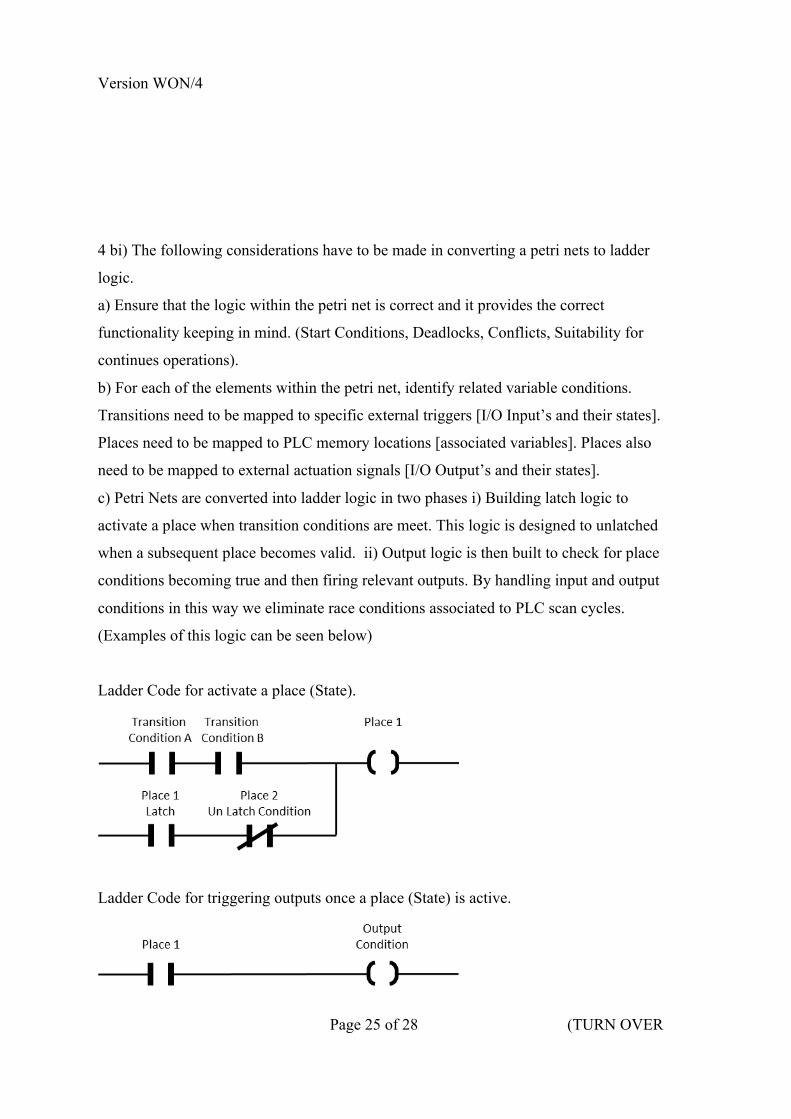
c) Petri Nets are converted into ladder logic in two phases i) Building latch logic to
activate a place when transition conditions are meet. This logic is designed to unlatched
when a subsequent place becomes valid. ii) Output logic is then built to check for place
conditions becoming true and then firing relevant outputs. By handling input and output
conditions in this way we eliminate race conditions associated to PLC scan cycles.
(Examples of this logic can be seen below)
Ladder Code for activate a place (State).
Ladder Code for triggering outputs once a place (State) is active.

Version WON/4
Page 26 of 28 (Cont.
4 bii) Petri Net in Area A converts to the following Ladder Logic.
Fixture A Free
Load A Button
Component A Available
Load Part
A
Load Part
A
Clamp Part
A
Load Part
A
Part A Loaded
Clamp Part A
Clamp Part A
Drill Rivet
Part A & B
Drill Rivet
Part A & B
Clamp Part A
Part A Clampe
d
Drill Rivet
Part A & B
Un Load Riveted Parts
Load Part
A
Clamp Part A
Drill Rivet
Part A & B
OP1
OP2
OP3

Version WON/4
Page 27 of 28
Examiners Comments
The question was answered with a good spread of marks across each section of the
question. 4ai (Describe the function of the petri net state (S2) designated Robot Loader) all candidates could understand a petri net diagram and that state S2 was used for conflict control. In question 4aii and 4aiii (modify the petri net to ensure Component A is loaded and clamped in place before Component B) and (modify the petri net so that the Robot Loader is also used to unload the finished riveted part) a very mixed response was provided by candidates. The modification of a petri net to allow for new logic was challenging. 4bi (Discuss factors that need to be considered when converting a Petri Net to Ladder Logic) had a good response from candidates with varying levels of discussion. 4bii (Converting a petri net shown into ladder logic) again had a very mixed responses from candidates.
W. O’Neill
June 2016

Version WON/4
Page 28 of 28
THIS PAGE IS BLANK