yokogawa centum cs3000.pptx
TRANSCRIPT

By: KHALID SHAPOGUMRY DCS&FPF FOREMAN
YOKOGAWA CENTUM CS3000
TRAINING
BEJING- CHINA MARCH 2010
Why we use control system…?Control system is reducing the
operation cost by reducing man power.
Control system is improving the product quality and reducing the waste time by reducing the error factor and high responding to the errors.

Pressure control loop


Block diagram for control loop
PID control loopProportionIntegralDerivative
The controller calculate the integral & derivative of the errors between the process variable and set point then generate a control effort by adding these two quantities to the error it self.

PID advantagePID is the most widely control
system in the projects.Simple configuration.High stability.High reliability.Simple operation.

PID controller with auto –man mode
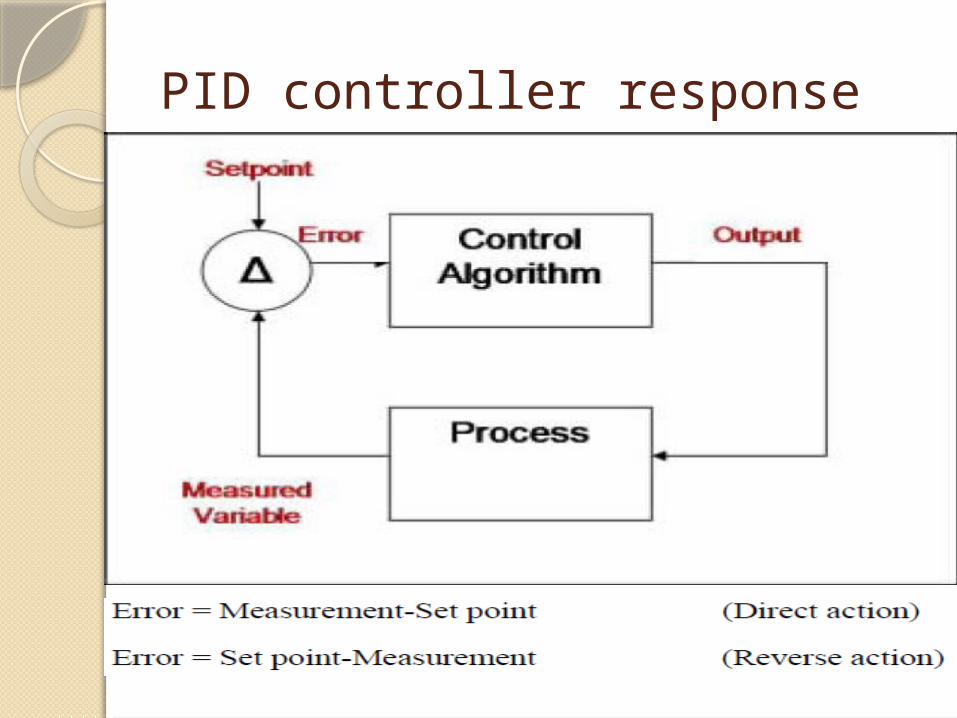
PID controller response

CASCADE CONTROL
Simply the Cascade control loop consist of two control loops interact together the output of the first controller(master controller) is the set point for the control device, and the second loop is slave loop.

CACADE CONTROLO LOOP


Enterprise Technology & Solution
Business (Top Management) Domain Corporate Information systems Enterprise Resource Planning (ERP) Supply Chain Management (SCM)
Control Domain Advanced Application Advanced Process Control (APC) Advance Operation Assistance (AOA) Plant Control Room/Factory Floor DCS/PLC/PC/ESD/F&G
Field DomainFieldbus and conventionalField Instrumentation.
Manufacturing Exec. System Domain Plant Information & Management System (PIMS) Maintenance Management (MM)
Field Domain
Control Domain
MES Domain
BusinessDomain

Field Domain - for field instruments, control valves, Field bus instruments in this domain etc.. Control domain - DCS/PLC/PC/ESD etc as major equipment in this domain. DCS is mainly carrying out Basic Regulatory Control (BRC) and Enhanced Regulatory Control (ERC) i.e. combination of calculation and other blocks to provide final control. APC add value on top of BRC/ERC to provide yield improvement, precise product quality control, Economic optimization of energy consumption (steam, power……). Ultimately APC provides economics benefits.DCS and other systems, besides control and automation function provides major plant operation. When plant in a normal operating condition, Automatic control and APC are in action. To further enhance the plant operation and carry out automatic and guided operation e.g. automatic startup/shutdown etc. AOA is our solution which helps in faster and safe startup/shutdown. Ultimately AOA provides economic benefits as well as safe operation. .

MES Domain - Our MES and solutions practically fulfills all needs of production & maintenance staffs all process and equipment related historical and real time information. Further it bridges the information gap between Control domain and Business domain. e.g. Material balance calculations at MES level provides information on efficient working of process to production management. At the same time at Business domain material balance information is used by Finance management for understanding of production economics.
Business (Top Management) Domain Corporate Information systems Enterprise Resource Planning (ERP) Supply Chain Management (SCM)
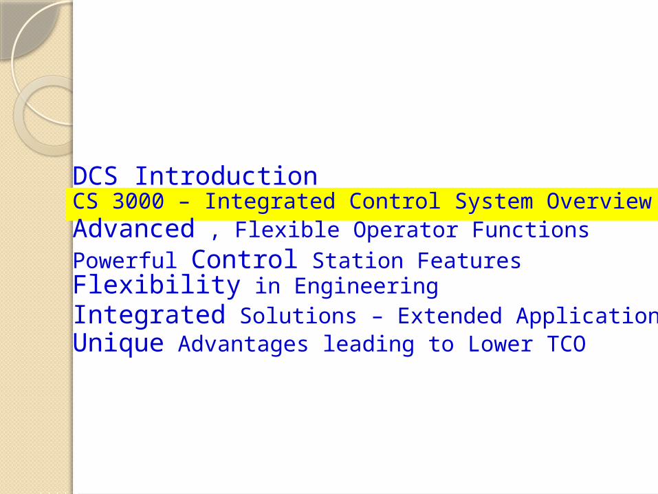
DCS Introduction
Advanced , Flexible Operator FunctionsPowerful Control Station FeaturesFlexibility in EngineeringIntegrated Solutions – Extended Applications
CS 3000 – Integrated Control System Overview
Unique Advantages leading to Lower TCO

7DF 7VP
7FS
F-BUS
COPS
CFCS
HF-BUS
COPS2
CFCS2
COPSV
CFSS
XLAIS EOPS ENGS
EFCS
CENTUM-V
CTM -2
COPS
7DF
THE FIRST DCS
SYSTEM IN THE
WORLD 1. Distribution of Control
2. FIF
NEW MODEL
1.
High Speed Comunication Bus
2.
Adoption of HDD
3. CMOS Memory
4. One-Touch Operation
(Function Key Development)
1.
Enhanced Functions of OPS
2.
Voice Output
3.
Japanese Language Support
4.
Sequence-oriented Control Station
EXCELLENT SYSTEM
1. Function Assignment
2. Separation of Engneering
3. High Peroformance
4. Touch Operation
5. Window
6. Integration (Super Window)
7. Expanded Control Capacity
CFFS
HF/F Converter
Station
CENTUM-XL
Computer
Station
ICS
FCS BCV
C ENTUM CS
INTEGRATED SYSTEM
V net 10Mbps
1Mbps
256Kbps
Control Loops
Sequence Tables
32 20
32 2
0
40 40
40 200
80 200
4096 Blocks
’75 ~’ 78
1. Unified Operator
Stations
2. Redundant
Control Stations
USER ORIENTED
OPERATION
1. UNIX OS
2. Advanced Control
3. Open Net Work
4. High Reliability
5. Utilisation of Users’ Assets
6. Easy Engineering
HIS
CENTUM
CS3000
OPEN SYSTEM
1. WINDOWS-NT OS
2. Client / Server
3. Migration
4. High Reliability
’79 ~’ 82’82 ~’ 88’84 ~’ ’98 ~’’92 ~’’88 ~’

Technology waves on Control Systems
Windows 2000InternetIT
time
UNIX
NTandMicrosoft
Micro processor
CS 3000CSXL1st CENTUM V
June 1975 ’82 ’88 ’93 ’98
CS 3000 R3
‘01

Integrated Plant Control System (IPCS)
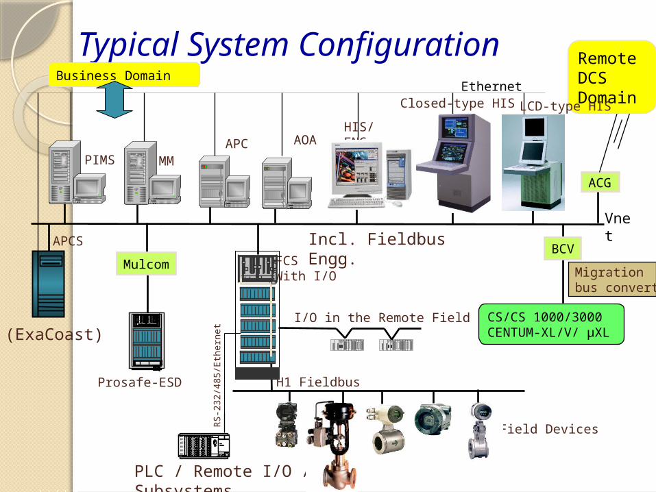
Typical System Configuration
Vnet
HIS/ENG
Prosafe-ESD
FCSWith I/O
Ethernet
CS/CS 1000/3000CENTUM-XL/V/ µXL
BCV
ACG
Remote DCS Domain Closed-type HIS
H1 Fieldbus
Migration bus converter
LCD-type HIS
APCS
Mulcom
I/O in the Remote Field(ExaCoast)
Incl. FieldbusEngg.
PLC / Remote I/O / Subsystems
RS-
232/
485/
Eth
erne
t
Field Devices
Business Domain
PIMS
AOA
MMAPC
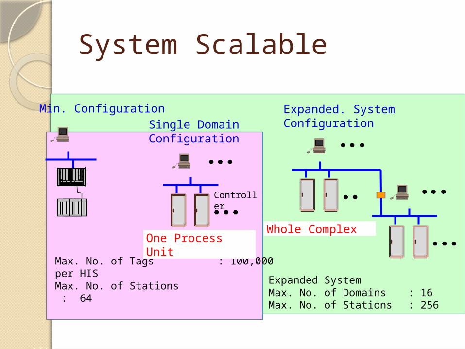
System Scalable
Min. ConfigurationSingle DomainConfiguration
Max. No. of Tags : 100,000 per HISMax. No. of Stations : 64
Expanded SystemMax. No. of Domains : 16Max. No. of Stations : 256
Expanded. SystemConfiguration
One Process UnitWhole Complex
Controller

Operation and Monitoring
Standard Operation and Monitoring WindowsGraphic,Tuning, Trends, Alarms, Operator guidance
Operation and Monitoring Support FunctionsProcess & Historical message reports, Security ITV camera & CENTUM desktop customization
Control Status Display WindowControl drawing, Sequence table Logic chart window SEBOL & SFC windows
Trend FunctionsReal time, Historical trends Long term data archive, External recorder, Expert trend viewer &Tuning trend
Common Operation and Monitoring FunctionsWindow call-up, Window” or “Full screen”, System message, Window sizing, Window hierarchy, Navigator window…
System Maintenance FunctionsSystem status, System alarm, HIS setting, Time setting dialog & Help dialog
Lets have a look at some samples
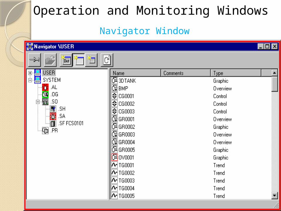
Operation and Monitoring WindowsNavigator Window

Control Group Window

Tuning Window

Overview Window

Trend Window
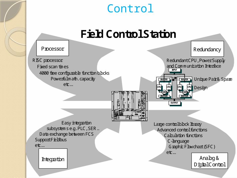
Field Control StationRedundancyProcessor
Analog &Digital Control
Integration
Large control block library Advanced control functions Calculation functions C-language Graphic Flowchart (SFC) etc...
Redundant CPU, Power Supplyand Communication Interface
Unique Pair & Spare
DesignCOMP
CPU CPU
BUFFER
COMP
CPU CPU
BUFFER
INPUT
OUTPUT
BUFFER BUFFER
RISC processor Fixed scan times 4000 free configurable function blocks Powerful math. capacity etc...
Easy integration subsystems e.g. PLC, SER.. Data exchange between FCSSupport Fieldbusetc...
Control

Input Output
RS-232C
RS-422
RS-485
Communication unitDigital I/O unit connector type
16 -pt. Input (isolated)
16 -pt Output (isolated)
32 -pt. Input
32 -pt. Output
Current/Voltage InmV, Thermocouple, RTD
InputPulse InputCurrent/Voltage Out
Analog single card I/O Unit
Voltage Input
mV Input
Thermocouple Input
RTD Input
2-wire transmitter input
4-20 mA Output
Analog Multiplexer Unit (16 channels)
RIO bus (max. 20 km)
Node Interface UnitMax. 8 units per FCS
Input / Output UnitsMax. 5 units per NIU
I/OUnit32 channels
I/OUnit2 ports
I/OUnit16 channels
I/OUnit128 channels
Input/OutputModules
Fieldbus
Profibus
Ethernet

Field Control Station and FIO feature
......
・・・・
To Field Device
To Field Devices
Fieldbus
Vnet
New Remote I/O Bus
Direct Node
(Ethernet)
FIO Features Small-sized
(Compact) Two kinds of
connection Direct Node Remote Node
Dual redundant I/O Module are possible (for all type)
Field Network RS:2 ports FF-H1 : 4
segments Profibus-DP
PLC(Subsystem)
FF-H1
Serial,Ethernet
4-20mA (Conventional)
FF-H1
4-20mA
Remote Node
FCS

FIO Node overview
写真挿入
Power supply
(10Base2)Remote I/O Interface
Up to 8 I/O modules
5 units (222.3mm)
19 inches

Rich Flexibility: Field connections
I/O module
Field wiring method according to the application & budget
Pressure Clamp Terminal block (Direct wiring for field devices)
Yokogawa Terminal Board, Cable & I/O adapter(Wiring of field devices via Terminal Boards/marshaling)
Terminal Board & MIL Connector Cable(Popular for low cost installations-Wiring of field devices via Terminal Board/Marshaling)

Remote I/O installation
Separated sites
Corrosive sites
Explosive sites
FCU
ooo
CCR (Central Control Room) Separated sites
Corrosive sites
Explosive sites

Field Control Unit: RedundancySynchronous hot standby with fully redundant
hardware and duplex functionality in design

EngineeringOff line Engineering without Target Hardware by using Hardware Simulation Technology
Engineering can start direct after orderingEngineering up to Configuration Testing can be done Off Line
Off line Testingand HardwareSimulation
CAEComputer Aided Engineering
ConcurrentEngineering
ElectronicMediaInput
Order Start-up
HIS
V net
FCS
ENGBuilder software

Virtual Test Function
Off line Testing
FCSSimulator
HISFunction
Virtual Testing
Vir
tual
Wir
ing FCS
Simulator
HIS Function
Plant Model
Plant Simulator
HIS
Exatif Communication Interface
HIS
- Off Line Virtual Testing using only one PC- Connection with Plant Simulator using the FCS Simulator


Unified configuration with LOOK&FEEL.
Project(Each plant)
Each folder for each FCS
Each folder for each HIS
Drag&Drop enables Copy& paste
Detail configuration for each
Example : Control logic
•Graphical configuration•FB in FCS and FF devices are handled in a same tool.
FB : Function Block

Flexible Field Wiring.
Terminal board
Field wiring
Field wiring
Dedicated cable
According to your plant, any I/O modules can be connected with direct connection or terminal board connection.
Even in case of field bus, you can choose either type.
Change the front blocks, you can change how to connect the field wiring.

Flexible Field Wiring.
Terminal board
Dedicated cable
For single
For dual

On-line maintenance.
In your plant operation, sometimes you would like to modify or to add/remove your control logic or graphics.◦ It is quite difficult (nearly impossible) to stop your controller
frequently.◦ You usually configured several control loops.
While modifying one of loops, you do not want to effect the control of any other loops.
R3 provides the “On-line maintenance” function to meet your above requirement. ◦ You need not stop your controller when you modify small parts
of control logic, graphics, etc.◦ Any other parts of control logic are effected by this
modification, so the influence for your plant control is minimum.

On-line maintenance.
Control logic
ooo
Controlling
(1) R3 Controller is controlling the plant with its control logic.
(2) You modify one of control loops. (or sequence logic etc.)Only this loop is stopped.Others are going on working.
(3) Modified item loop is retrieved on-line to actual control without any effect to other loops.
(4) In this term, CPU of controller never stops.
No effect
No effect
No effect
No effect
No effect
No effect
Controller CPU is Non-stop !
