xyter
DESCRIPTION
xyter. Proton beam at CBM FAIR Total cross-section trigger at SPS CERN Tagged neutrino beam for LHC. DETNI-A 157 Gd/Si Detector Module. Goals 10 8 n/sec in 100 cm 2 with 2 views, 2 hit/strip: 400 MHz strip hit rate with 5 Byte/hit: 2 GByte/sec data Consequences 128 channel ASIC - PowerPoint PPT PresentationTRANSCRIPT

xyter

Proton beam at CBM FAIR
Total cross-section trigger at SPS CERN
Tagged neutrino beam for LHC

DETNI-A DETNI-A 157157Gd/Si Detector ModuleGd/Si Detector Module
slide courtesy C.J.Schmidt
100 mm
GoalsGoals• 108 n/sec in 100 cm2
• with 2 views, 2 hit/strip:400 MHz strip hit rate
• with 5 Byte/hit:2 GByte/sec data
ConsequenceConsequencess
• 128 channel ASIC• 20 chip/module• 20 MHz/chip• 100 MByte/chip

• Measurement of time, energy and position• Data acquisition speed ~ 1Gbps• Input Clock ~ 250MHz• Input channels ~ 1024 or higher• Data - 8-bit parallel after flash ADC• ADC – Flash type 8-bit (MAX-106 600MSPS)• Time stamp, channel-ID and status signals 32 bit(8-bit parallel x 4
packet)
Understanding Data Acquisition System for N-XYTER
www.gsi.de/documents/DOC-2007-Aug-28-2.ppt

N-XYTER Block Schematic

AA collision: <Ntrack> = 3000 <t> = 1000 ns
pp collision: <Ntrack> = 3 <t> = 1 ns
Identical occupancyin AA and pp per microsec but 1000 times lessin pp in nanosec window
xx
x
x
x
xx
x
xx
xxx
xxxx xx x
x
xxxxxxx xx
x
x
xx
xx
xx
xx x
xx
xxxxxxx
pp AA
Strip readout Pixel readout required
or

High transverse momentum means high 3-momentum
Illustration for mid-rapidity at sqrt(s) 7 and 14 GeV
( )ELab
( )( ) =plong
ptrans 0 0 1
0
0
22Tpm
0
longp >= 0Lab
E >= 22Tpm
ptrans
Beam ptrans Lab
E
25 55525 2 5
5 22


No need for pixel detector for pp, pA high PT
Less than 3 hits per cell: (x,y) and (u,v) gives unique solution

Total cross-section trigger

TargetBeam
NEAR FAR
Valid interaction
min
SHINE TPC experiment less than 107 proton/sec
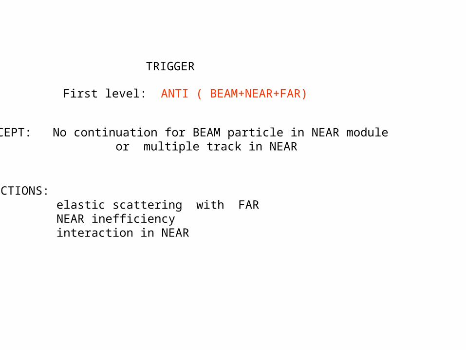
TRIGGER
ACCEPT: No continuation for BEAM particle in NEAR module or multiple track in NEAR
CORRECTIONS: elastic scattering with FAR NEAR inefficiency interaction in NEAR
First level: ANTI ( BEAM+NEAR+FAR)

Proposal for UNK, Serpukhov

LHC tagged neutrino possibility
Slow beam-dump
Total fill about 1015 proton , extraction time 3 hours: 1011 proton/s
Secondaries with few hundred GeV: 1012 p/s decay probability: 10-3
Number of decay muons at tagging station: 109 /s
Ideal rate for XYTER
Assumption: “point-like” proton beam target , i.e. interaction point is knownwith reasonable accuracy.
Much less load (faster extraction) for neutral K beam.

Z
Unknowns: decay point: ZD and momenta: P,P,P
Decay zone Shielding
XYTER-wall

Unknowns are only the momenta: PK,P,P,P
MAGNET
Decay zone Shielding
XYTER-wall
Possible e,identification


Understanding Data Acquisition System for N-
XYTER
www.gsi.de/documents/DOC-2007-Aug-28-2.ppt

Set-up Requirements
• Measurement of time, energy and position• Data acquisition speed ~ 1Gbps• Input Clock ~ 250MHz• Input channels ~ 1024 or higher• Data - 8-bit parallel after flash ADC• ADC – Flash type 8-bit (MAX-106 600MSPS)• Time stamp, channel-ID and status signals 32
bit(8-bit parallel x 4 packet)
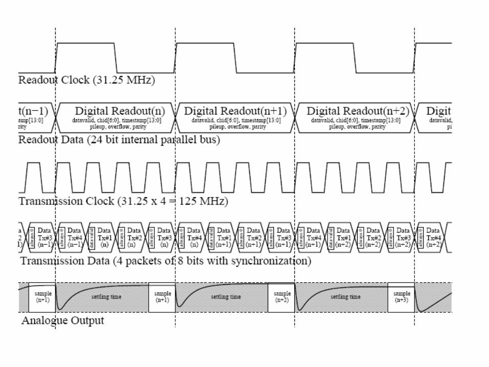

Data packet for time-stamp channel-id and status signals
Differential analog output in N-XYTER

Some parameters form CBM• Each channel detects autonomously all hits
• An absolute time stamp, precise to a fraction of the sampling period, is associated with each hit
• All hits are shipped to the next layer (usually concentrators)
• Association of hits with events done later using time correlation
• Typical Parameters:
– with few 1% occupancy and 107 interaction rate:
• some 100 kHz channel hit rate
• few MByte/sec per channel
• whole CBM detector: 1 Tbyte/

1Gbps FOL
Basic Idea for Readout for 4-chip FEE board
FEE-board Readout controller (ROC)
Serial fiber optic peripheral

Basic n-XYTER Readout ChainBasic n-XYTER Readout ChainDetector
FEB ROCX
YT
ER
XY
TE
RX
YT
ER
AD
C
XY
TE
R
Tag data
Tag data
Tag data
Tag data
ADC data
clock
F
PGA
control
SFPMGT
ABB
F
PGA
MGT
MGTMGT
Front-EndBoard
Read-OutController
Active BufferBoard
Bond orcableconnection
up to 8 N-XYTER1024 ch.
LVDSsignalcable
2.5 Gbpsopticallink
1-4 lanePCIeinterface

Scalable n-XYTER Readout ChainScalable n-XYTER Readout Chain
Detector
FEB ROCX
YTER
XYTER
XYTER
AD
C
XYTER
Tag data
Tag data
Tag data
Tag data
ADC data
clock FP
GA
control
SFPMGT
DCB
F
PG
A
SFP MGT
MGT
Front-EndBoard
Read-OutController
Data CombinerBoard
to otherROC's
to ABB
SFP
SFP MGT
MGT

PC
Some ConfigurationsSome Configurations
Detector FEB ROC ABB
PC DCB ABB
Detector FEB ROC
Detector FEB ROC
Detector FEB ROC
Detector FEB ROC
Minimal Configuration
Expandable Configuration
Data Combiner Board

OLDER READOUT EXPERIENCE
MANAS MANAS MANAS MANASMARC
ADC ADC
FEE BOARD
TRANSLATOR BOARD
DAQ
LVTTL DATA and CONTROL lines
LVDS LINK

Proposed idea to have the test set-up
Exixting CROCUS DAQ can be used as ABB card just to make the ROC card with FEE board
1Gbps link
ROC
FEE External board with FPGA and Buffer
SIU used in CROCUS DAQ

Proposed N-XYTER Readout scheme
NXYTER
NXYTER
NXYTER
NXYTE
R
ADC
ASIC based ROC
LVDS CONTROL and DATA lines
DCB with 10 Gbps SFP link
FEE BOARD
To other FEE boards
OFC link
DAQ

Readout controller (ROC) board
• Raw data and memory management
• Data acquisition and processing (data tagging).
• Data transfer at 1Gbps by Multi gigabyte Tran-receiver (MGT) and then send via serial fiber optic link of 1Gbps
• I2C driver for N-XYTER configuration and slow control.
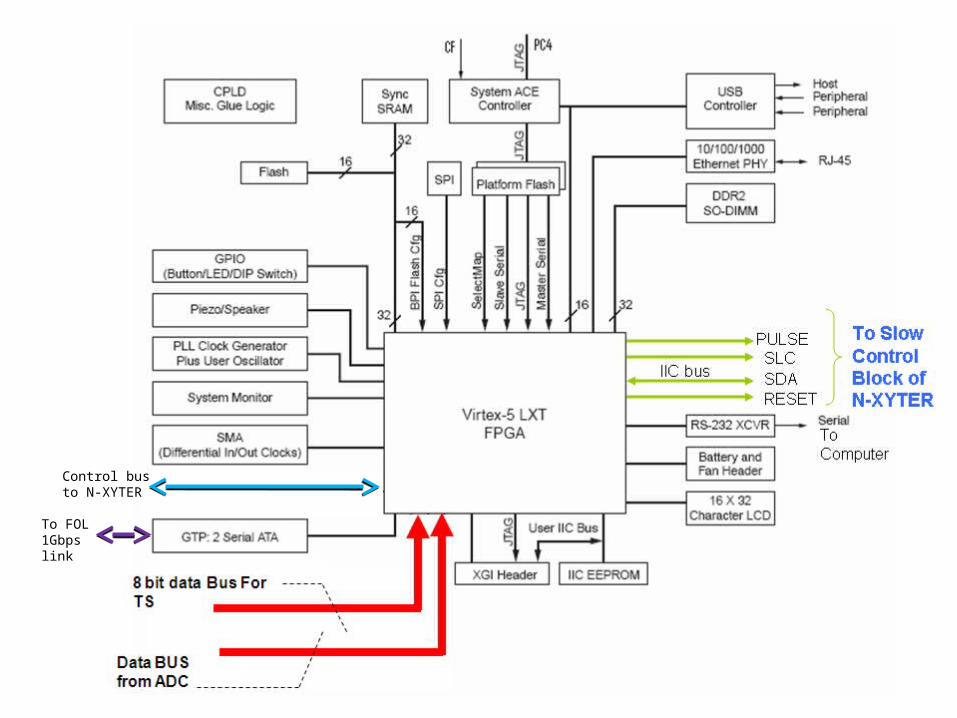
Control bus to N-XYTER
To FOL 1Gbps link

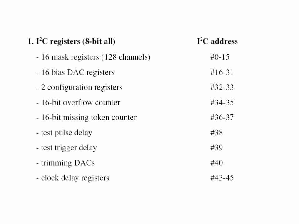
N-XYTER Chip configuration
• All internal bias, thresholds and DAC references are programmable through I2C slow control @ 100Kbps by total 46 resisters.
• ROC board is to be built to program and to control above mentioned control resisters and FPGA program can be changed by JTAG port.
• Next slide shows proposed scheme for N-XYTER configuration and control through I2C bus.


N-XYTER N-XYTER N-XYTER N-XYTER
SDA
SLCFPGA
I2C_ID0 I2C_ID6 I2C_ID0 I2C_ID6 I2C_ID0 I2C_ID6 I2C_ID0 I2C_ID6
I2C Programming Scheme

Algorithm
• Configuration data to be entered form computer to FPGA via RS-232 interface and stored in IIC EPROM.
• On start or restart of the system configuration data to be transferred to the N-XYTER through IIC bus.
• Status resister can be read back from N-XYTER through RS-232 port.

• For configuration of the XYTER to set the threshold values and control words, a LINUX based platform is used in the PC. The software in the PC extend the facility to configure all the control Words and the same can be down loaded to the EEPROM on the ROC board through RS232 link . The EEPROM is connected through a IIC bus to FPGA and configure the XYTER with SOFTWARE CONTROL from the PC
• The ROCKET IO/ GTP provide data at 1GBPS in the serial format • The standard Desk Top PC has a limitation to acquire data at
1GBPS so a SERVER is required to handle the High-speed data @1gbps from the ROC board through light link
• JTAG PROGRAMMING – The FPGA selected are nonvolatile and reprogrammable. However for
programming the JTAG port is available at the board .
– We require XILINX ISE software and JTAG Cable for development and downloading the software.
Computer Control

UART-BLOCKRS-232
BUS-Controller Block
Center Control-Block
GTP-Controller SIU
SERVER
MEMORY
I/O and Contol Bus to N-Xyter

V-4 MGT basedoptical link
V-4 MGT basedPCI-Express interface(4 lanes)
Active Buffer Board
This board is under construction and is expected soon.

Thank You