xr1000 user manual - xorcom · document information this document is numbered #xr1000, revision 1.1...
TRANSCRIPT

XR1000 USER MANUAL

Document Information
This document is numbered #XR1000, Revision 1.1 and was released February 2008.
Contact Information
Xorcom Ltd., a contributing member of the Asterisk community, develops software and hardware for the open source Asterisk PBX environment. Our goal is to make Asterisk a friendly, easy–to–install and easy–to–use system, enabling fast and simple installation and configuration of PBXs of all sizes. Visit our web site at: http://www.xorcom.com Contact us at: [email protected]

Table of Contents
INTRODUCTION ..............................................................................1
Package Contents ................................................................................................. 2
System Overview .................................................................................................. 2
Installation ............................................................................................................ 3
LED Indicators ..................................................................................................... 6
Device Status LEDs ........................................................................................ 6
Analog Line Status LEDs ............................................................................... 7
Log-in and Overview of the XR1000 Configurator ........................................... 7
SYSTEM CONFIGURATION ..........................................................9
System Summary ................................................................................................ 10
WAN Settings ...................................................................................................... 11
VPN Settings ....................................................................................................... 13
LAN Settings ....................................................................................................... 15
Firewall ................................................................................................................ 17
Adding or Editing a Firewall Restriction ...................................................... 17
Removing a Firewall Restriction .................................................................. 20
Time Zone ........................................................................................................... 21
SMTP Mail Server .............................................................................................. 22
i

Syslog ....................................................................................................................23
Change Password ................................................................................................24
THE MAINTENANCE MENU ...................................................... 25
View Logs .............................................................................................................26
Backup and Restore ............................................................................................27
Tune FXO ............................................................................................................28
CDR ......................................................................................................................30
System Cleanup ...................................................................................................30
Software Update ..................................................................................................31
Remote Support ..................................................................................................32
Restart the Server ...............................................................................................32
PBX CONFIGURATION ............................................................... 33
Overview ..............................................................................................................34
Running the PBX Configurator .....................................................................34
Principles of Dialing Plan Configuration ......................................................35
Special Phone Numbers for Accessing PBX Service ....................................38
Adding User Extensions .....................................................................................39
Enabling Conferencing .......................................................................................42
Configuring Voicemail .......................................................................................44
ii XR1000

Configuring Call Queues ................................................................................... 46
Adding Service Providers .................................................................................. 48
Calling Rules ....................................................................................................... 52
Incoming Calls .................................................................................................... 55
Voice Menus ........................................................................................................ 57
Time Based Rules ............................................................................................... 60
Call Parking ........................................................................................................ 62
Defining Call Parking Extensions ................................................................. 62
Using Call Parking ........................................................................................ 63
Ring Groups ........................................................................................................ 64
Record a Menu .................................................................................................... 66
Administrator Monitors and Tools ................................................................... 67
Active Channels ............................................................................................ 67
Asterisk Logs ................................................................................................ 67
CDR Reader .................................................................................................. 68
Command Line Interface .............................................................................. 68
File Editor ..................................................................................................... 69
Options ................................................................................................................ 70
iii
SUPPORT AND TROUBLESHOOTING .................................... 73
Rescue, Restore, and Reflashing Firmware ......................................................74
Troubleshooting ..................................................................................................75
Common PBX Configuration Issues .............................................................75
FXS/FXO Channel Related Issues ................................................................75
VoIP Related Issues ......................................................................................78
PBX Configuration Internals .............................................................................82
XR1000 Configuration Tips ...............................................................................86
Recommended Process: Tweaking the Dialing Plan ....................................86
Deleting all Content of a Specific Voicemail Box ........................................86
Defining a Voicemail Box Number Different than the Extension Number ..88
Defining Shortcut Numbers ..........................................................................88
Cables Pin Out ....................................................................................................90
iv XR1000

SECTION 1:
INTRODUCTION
This section includes:• “Package Contents” on page 2• “System Overview” on page 2• “Installation” on page 3• “Connecting Analog Phones” on page 4• “Connecting Analog Lines” on page 5• “LED Indicators” on page 6

Package Contents Please ensure that the package contains the following:
• The XR1000 (10 inch or 19 inch width unit)• External desk-top 12V 5A power supply unit• Power cord• Support hardware for 19'' cabinet (for 19'' full-size units only)• The Xorcom CD-ROM• The Getting Started leaflet
System OverviewThe XR1000 is an embedded DSP-based Asterisk server. The device may be equipped with various combinations of up to 32 FXO and FXS ports, and with auxil-iary ports for external appliances such as door locks and alarm systems. The XR1000 can support up to 32 concurrent calls and, in addition, can support SIP and IAX2 phones and trunks. The XR1000 comes equipped with a reset-to-default-settings option that returns the appliance to the original factory configuration (see “Rescue, Restore, and Reflashing Firmware” on page 74). In the event that the device has been damaged by improper modification—for example, by a programmer that make an erroneous code change even at the systems code level—the rescue option can save the XR1000 and return it to factory specifica-tions.For a full list of available XR1000 models, visit our web-site:
http://www.xorcom.com/products/xr1000/xr1000_models
2 XR1000

InstallationTo install the XR1000:1. Select an appropriate location. The location must allow ample air circulation
around both the power supply unit and the XR1000 box.
WARNING! Never cover the power supply unit or the XR1000 box. WARNING! Never use a power supply unit that was not supplied with the XR1000 box. Connecting other power supply units may damage the unit permanently and voids the warranty.
2. For safety reasons, if the line wiring exits the building, it is essential to use the ground the unit. a. Connect a grounding tab to the grounding screw on the rear panel. b. Using 12-16 gauge wire, connect the grounding tab to a reliable ground.
Figure 1: Grounding Screw on Rear Panel3. Connect the power supply unit to the power supply input on the back of the unit.
WARNING! Do not connect the device’s LAN port to your office network. If your network is equipped with a DHCP server, this might cause network conflicts.
4. Connect the device’s WAN port, on the rear panel, to the office network or to your local router.
WARNING! Regarding step #5, use a grounded power source.
5. Connect the power supply unit to an electric outlet.6. Wait about two minutes. The startup time will depend upon the number of tele-
phony ports you have installed in your device.The FXS ports of the XR1000 will be operative about 30 seconds after the SYNC LED, located on the front panel, starts to blink.
Grounding
Power supply
Installation 3
7. Determine the IP address of your XR1000. If a DHCP server is available on your office network, an IP address has already been assigned to your XR1000. If not, configure the IP address manually (see “WAN Settings” on page 11). There are two ways to determine the IP address:Using an analog telephoneConnect a phone to an FXS port and dial *66. The unit will announce the IP address.Using the Web interfaceTo check the IP address via a browser:a. Using a standard Ethernet cable, connect a computer to the XR1000’s LAN
port.b. Configure your computer to automatically obtain an IP address from a
DHCP server. The XR1000 will assign the address 192.168.1.xxx to your computer.
c. Start your Firefox Internet browser and enter 192.168.1.1 in the address field. The XR1000 web interface is displayed.
d. Log-in to the unit. The default user name is admin and the default password is 123456.
e. On the System Configuration navigation pane, click WAN and configure the WAN IP settings. See “WAN Settings” on page 11 for a complete explanation of this procedure.
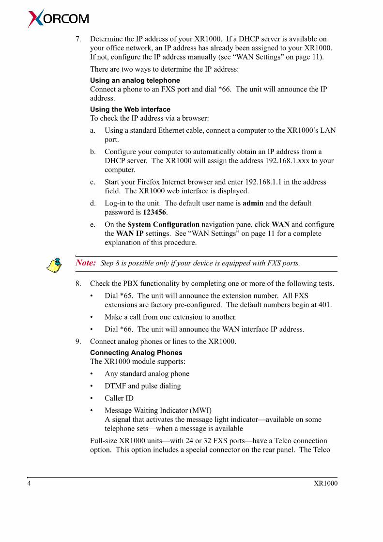
Note: Step 8 is possible only if your device is equipped with FXS ports.
8. Check the PBX functionality by completing one or more of the following tests.• Dial *65. The unit will announce the extension number. All FXS
extensions are factory pre-configured. The default numbers begin at 401. • Make a call from one extension to another.• Dial *66. The unit will announce the WAN interface IP address.
9. Connect analog phones or lines to the XR1000.Connecting Analog PhonesThe XR1000 module supports:• Any standard analog phone• DTMF and pulse dialing• Caller ID• Message Waiting Indicator (MWI)
A signal that activates the message light indicator—available on some telephone sets—when a message is available
Full-size XR1000 units—with 24 or 32 FXS ports—have a Telco connection option. This option includes a special connector on the rear panel. The Telco
4 XR1000

connection enables the use of a single cable to connect all the FXS ports (up to 32) to the patch panel without having to assign an RJ-11 cable for each FXS port. At the same time, all the front panel LED indicators for each channel are available, and the RJ-11 connectors on the front panel enable easy access for testing and maintenance of each port.
Figure 2: Telco Connection (Rear Panel)
Connecting Analog LinesThe XR1000 module supports standard PSTN lines.
WARNING! When connecting the XR1000 to PSTN lines, ensure that the lines are protected. Use standard lightning protection devices such as gas discharge units or similar solid state, high-energy protection devices. In addition, ensure that the unit has been grounded using the grounding screw (see step #2 on page 3).
Analog lines need to be tuned to adjust the port impedance to the telephone line impedance. Adjusting impedances can substantially reduce the echo that is gen-erated by the interface of a digital 4-wire system to an analog 2-wire system. See “Tune FXO” on page 28.
Installation 5
LED Indicators The LED sets on the front panel of a XR1000 include:• 4 red LEDs (upper left) that indicate device status• A green LED for each analog port• 4 additional red LEDs that are not used in the current version
Device Status LEDs
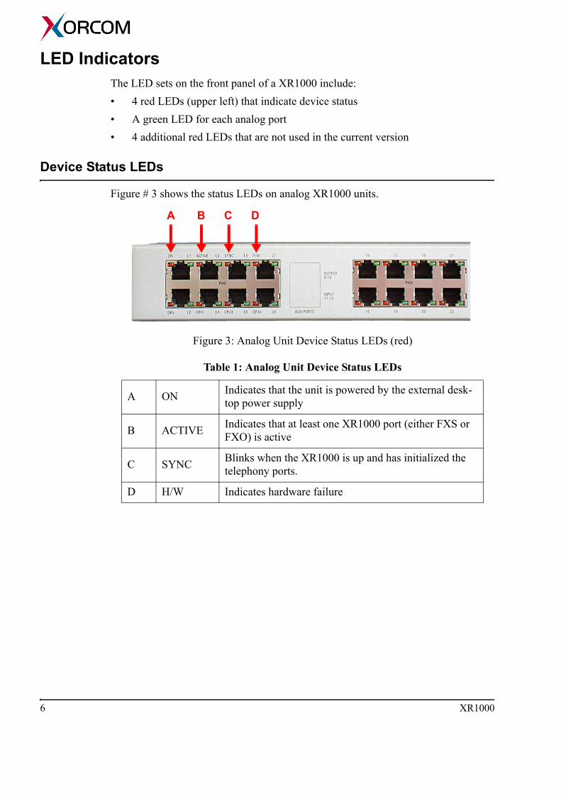
Figure # 3 shows the status LEDs on analog XR1000 units.
Figure 3: Analog Unit Device Status LEDs (red)
Table 1: Analog Unit Device Status LEDs
A ON Indicates that the unit is powered by the external desk-top power supply
B ACTIVE Indicates that at least one XR1000 port (either FXS or FXO) is active
C SYNC Blinks when the XR1000 is up and has initialized the telephony ports.
D H/W Indicates hardware failure
A B C D
6 XR1000
Analog Line Status LEDs
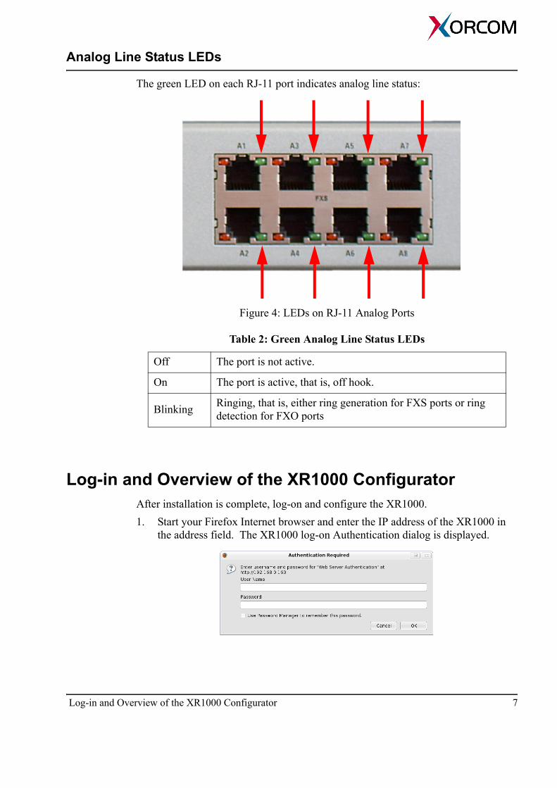
The green LED on each RJ-11 port indicates analog line status:
Figure 4: LEDs on RJ-11 Analog Ports
Log-in and Overview of the XR1000 ConfiguratorAfter installation is complete, log-on and configure the XR1000.1. Start your Firefox Internet browser and enter the IP address of the XR1000 in
the address field. The XR1000 log-on Authentication dialog is displayed.
Table 2: Green Analog Line Status LEDs
Off The port is not active.
On The port is active, that is, off hook.
Blinking Ringing, that is, either ring generation for FXS ports or ring detection for FXO ports
Log-in and Overview of the XR1000 Configurator 7

2. Log-in to the unit. The default user name is admin and the default password is 123456. The Summary screen is displayed.
The screen is divided into 4 sections:Buttons and links in the blue title bar The blue title bar, at the top of the screen, contains buttons and links, for example, the Save Configuration button and the Show Advanced Options link (see “Options” on page 70).
WARNING! All changes must be saved on the Flash Memory prior to rebooting. Any changes that are not saved will be lost in the reboot process. This is done with the Save Configuration button located in the upper-right corner of the screen.
The navigation panel on the left The navigation panel (pictured on right) is divided into 3 sections, PBX configuration, System configuration, and Maintenance. The configuration pane in the center Changes to configuration are entered in the center pane. Explanations of the configuration pane’s content on the right These explanation are often enough to help you complete the procedure. For more detailed explanations, open the Help.The PBX Configuration Panel opens in a separate window or tab of your Internet browser.
3. On the navigation pane, click PBX Configuration. 4. Configure the PBX. PBX configuration is fully documented
beginning on page 33.
8 XR1000
SECTION 2:
SYSTEM CONFIGURATION
The System Configuration menu includes the following:• “System Summary” on page 10• “WAN Settings” on page 11• “VPN Settings” on page 13• “LAN Settings” on page 15• “Firewall” on page 17• “Time Zone” on page 21• “SMTP Mail Server” on page 22• “Syslog” on page 23• “Change Password” on page 24

System SummaryThe System Summary provides an overview of the XR1000’s configuration. 1. Log-in to the XR1000 Configurator (see “Log-in and Overview of the XR1000
Configurator” on page 7).2. On the navigation pane, click Summary.
10 XR1000
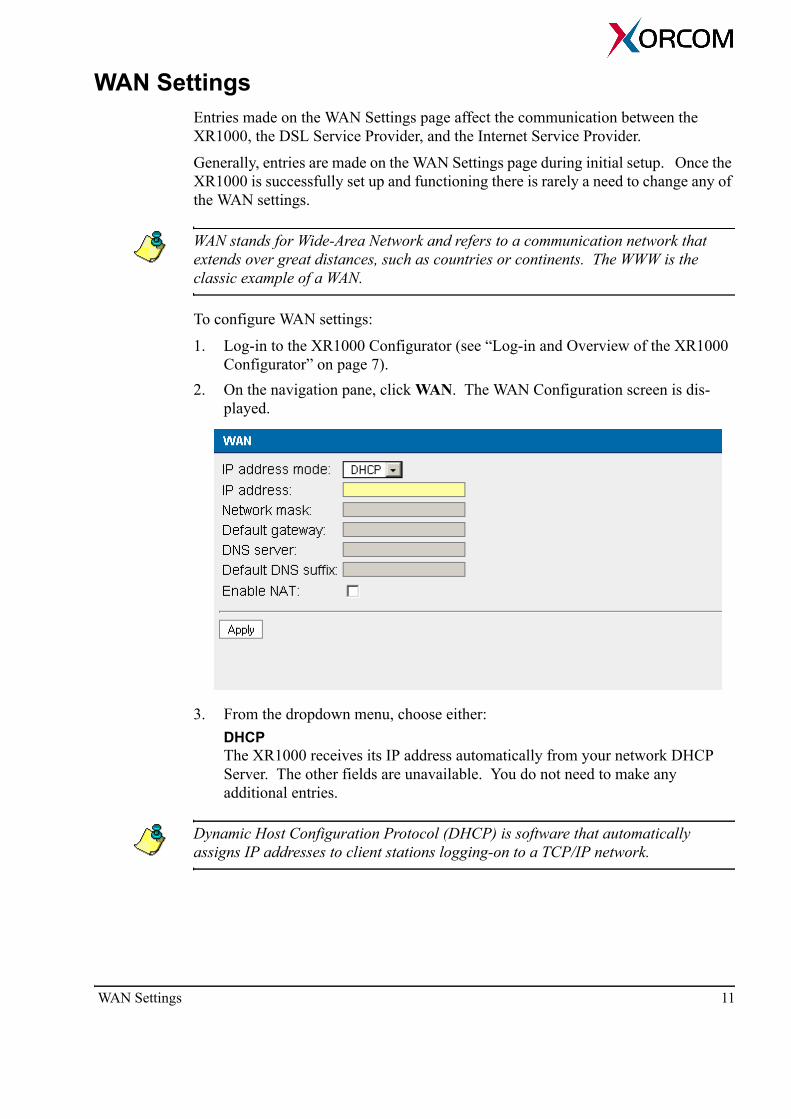
WAN SettingsEntries made on the WAN Settings page affect the communication between the XR1000, the DSL Service Provider, and the Internet Service Provider.
Generally, entries are made on the WAN Settings page during initial setup. Once the XR1000 is successfully set up and functioning there is rarely a need to change any of the WAN settings.
WAN stands for Wide-Area Network and refers to a communication network that extends over great distances, such as countries or continents. The WWW is the classic example of a WAN.
To configure WAN settings:
1. Log-in to the XR1000 Configurator (see “Log-in and Overview of the XR1000 Configurator” on page 7).
2. On the navigation pane, click WAN. The WAN Configuration screen is dis-played.
3. From the dropdown menu, choose either:DHCPThe XR1000 receives its IP address automatically from your network DHCP Server. The other fields are unavailable. You do not need to make any additional entries.
Dynamic Host Configuration Protocol (DHCP) is software that automatically assigns IP addresses to client stations logging-on to a TCP/IP network.
WAN Settings 11

StaticFor a static or fixed IP address, configure the following parameters:
• IP address Enter the IP address assigned to the XR1000.
• Network mask Enter the subnet mask assigned to the network to which the XR1000 belongs.
• Default gateway Enter the IP address of the default router used by the network to which the XR1000 belongs.
• DNS Server Enter the IP address of the Domain Name System (DNS) server. The DNS server maintains a list of domain names and their corresponding IP addresses, and executes the substitution.
• Default DNS suffix Enter the suffix that is automatically added to a resolver query if it contains a host name without dots. For example, if the DNS default suffix is “mydomain.com” and the XR1000 should find host “abc” then the DNS query will be performed for name “abc.mydomain.com”
NoneThe WAN interface is disabled. The other fields are unavailable. You do not need to make any additional entries.
4. Select or clear the Enable NAT checkbox. When selected, NAT is enabled between the WAN and LAN interfaces.
5. Click Apply. 6. To permanently save the changes, click Save Configuration.
12 XR1000
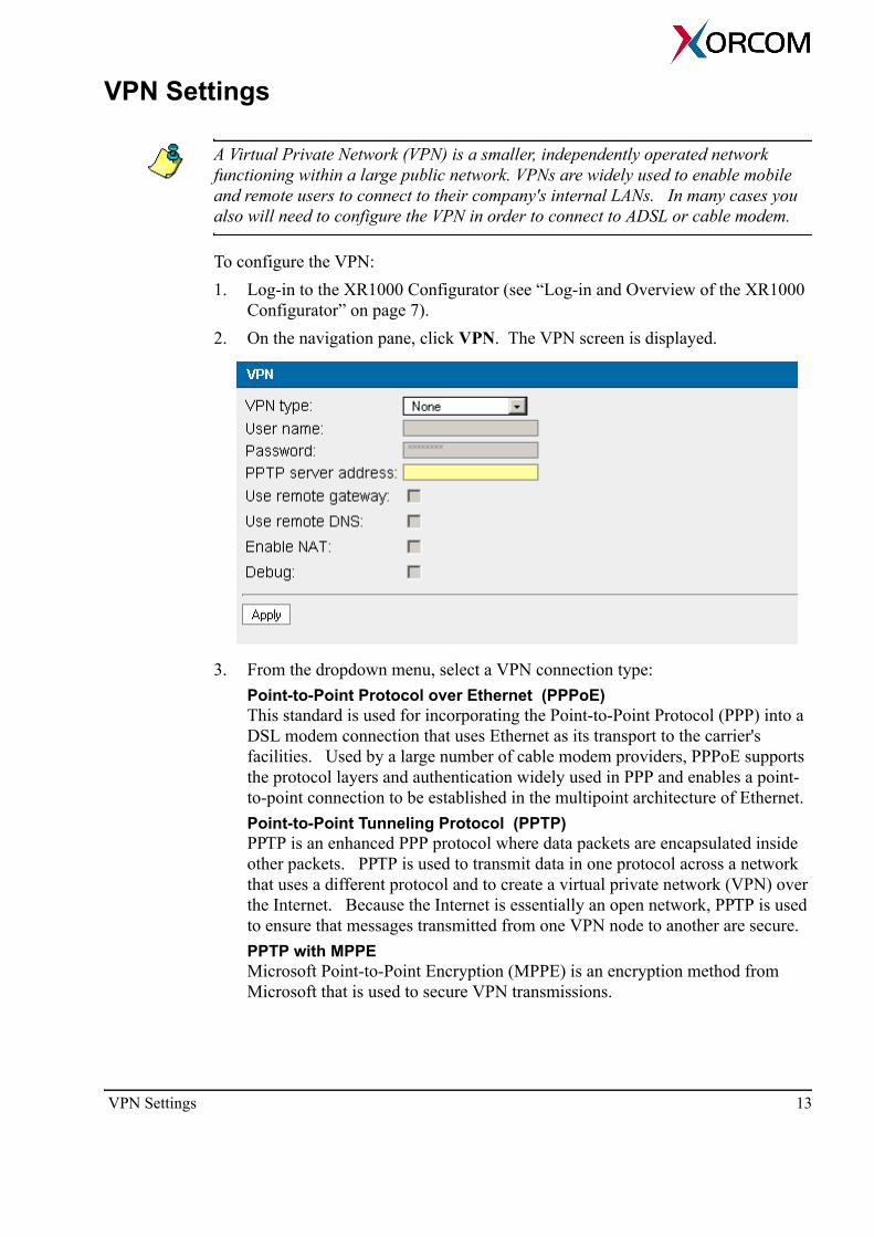
VPN Settings
A Virtual Private Network (VPN) is a smaller, independently operated network functioning within a large public network. VPNs are widely used to enable mobile and remote users to connect to their company's internal LANs. In many cases you also will need to configure the VPN in order to connect to ADSL or cable modem.
To configure the VPN:1. Log-in to the XR1000 Configurator (see “Log-in and Overview of the XR1000
Configurator” on page 7).2. On the navigation pane, click VPN. The VPN screen is displayed.
3. From the dropdown menu, select a VPN connection type: Point-to-Point Protocol over Ethernet (PPPoE) This standard is used for incorporating the Point-to-Point Protocol (PPP) into a DSL modem connection that uses Ethernet as its transport to the carrier's facilities. Used by a large number of cable modem providers, PPPoE supports the protocol layers and authentication widely used in PPP and enables a point-to-point connection to be established in the multipoint architecture of Ethernet. Point-to-Point Tunneling Protocol (PPTP) PPTP is an enhanced PPP protocol where data packets are encapsulated inside other packets. PPTP is used to transmit data in one protocol across a network that uses a different protocol and to create a virtual private network (VPN) over the Internet. Because the Internet is essentially an open network, PPTP is used to ensure that messages transmitted from one VPN node to another are secure. PPTP with MPPE Microsoft Point-to-Point Encryption (MPPE) is an encryption method from Microsoft that is used to secure VPN transmissions.
VPN Settings 13
4. Configure the following parameters: User name Enter the name used to identify XR1000 to the ISP. Password Enter the password used to identify XR1000 to the ISP. PPTP Server address (Required for PPTP only) Enter the IP address of the ISP’s Gateway.
5. Select or clear the following checkboxes:Use remote gateway When selected, the IP gateway address received during establishment of the VPN connection becomes the XR1000's default IP gateway. Use remote DNS When selected, the XR1000 uses the address of the DNS server received when establishing the VPN connection.Enable NAT When selected, the XR1000 will perform NAT between the VPN network interface and the LAN.Debug When selected, the detailed diagnostic messages will be sent to the system log. Log entries can be viewed on the View Logs screen (see “View Logs” on page 26).
6. To permanently save the changes, click Save Configuration.
14 XR1000

LAN SettingsEntries made on the LAN Settings page affect the communication between the XR1000 and the computers attached to it. If you don't use the XR1000 as an IP router—that is, no computers are attached to it— then you don't need to configure the LAN interface.Generally, entries are made on the LAN Settings page during initial setup. Once the XR1000 is functioning, there is rarely a need to change any of the LAN settings.
If a change is made that affects the IP addresses assigned to computers connected to the XR1000 LAN port, the computers themselves must be restarted.
To configure LAN settings:1. Ensure that you have accurate LAN settings. Most of the parameters necessary
for configuration must be assigned by the LAN Administrator. 2. Log-in to the XR1000 Configurator (see “Log-in and Overview of the XR1000
Configurator” on page 7).3. On the navigation pane, click LAN.
4. Define the IP address and the subnet mask used for the XR1000 LAN interface. This address may be used, for example, by the computers attached to XR1000 to connect to the XR1000 Router.
LAN Settings 15

5. Select or clear the Enable DHCP Server checkbox. Dynamic Host Configura-tion Protocol (DHCP) is software that automatically assigns IP addresses to client stations logging onto a TCP/IP network. XR1000 has a DHCP server and can assign IP addresses to the computers connected to its LAN interface.
XR1000's DHCP server can be enabled or disabled. If disabled, each computer must be assigned an IP address manually.
When selected, enter the following parameters: Authoritative A client computer can request the last-known IP address. If the address is a valid address for the LAN network, the DHCP server can grant the request. If the address is invalid and Authoritative is enabled, the DHCP server will immediately deny the request and the client will immediately ask for a new address. If Authoritative is disabled, the server will ignore the request. The client computer will ask for a new address only after its time out. Domain Optionally, define a domain name for the DHCP server. Once defined, the DHCP server will return that domain to the host computers that request it. Also, this defines the domain name which is legal for hosts to claim. Range start This is the first IP address the XR1000 will assign. Subsequent addresses are assigned consecutively. Range end This is the final IP address the XR1000 will assign.Maximum simultaneously leases This is the maximum number of DHCP leases that the XR1000’s DHCP server will support at any one time. This prevents DoS (Denial Of Service) attacks from computers that generate a large number of leases and cause the DHCP server to use too much memory. The default value is 150.Lease time This is the number of days an IP address assigned by the XR1000 remains unavailable even when the computer to which it was assigned does not renew the lease. For example, if Lease time is defined as two days, and a computer is removed or shut down, the IP address will become available after two days.
6. Click Apply. 7. To permanently save the changes, click Save Configuration.
16 XR1000
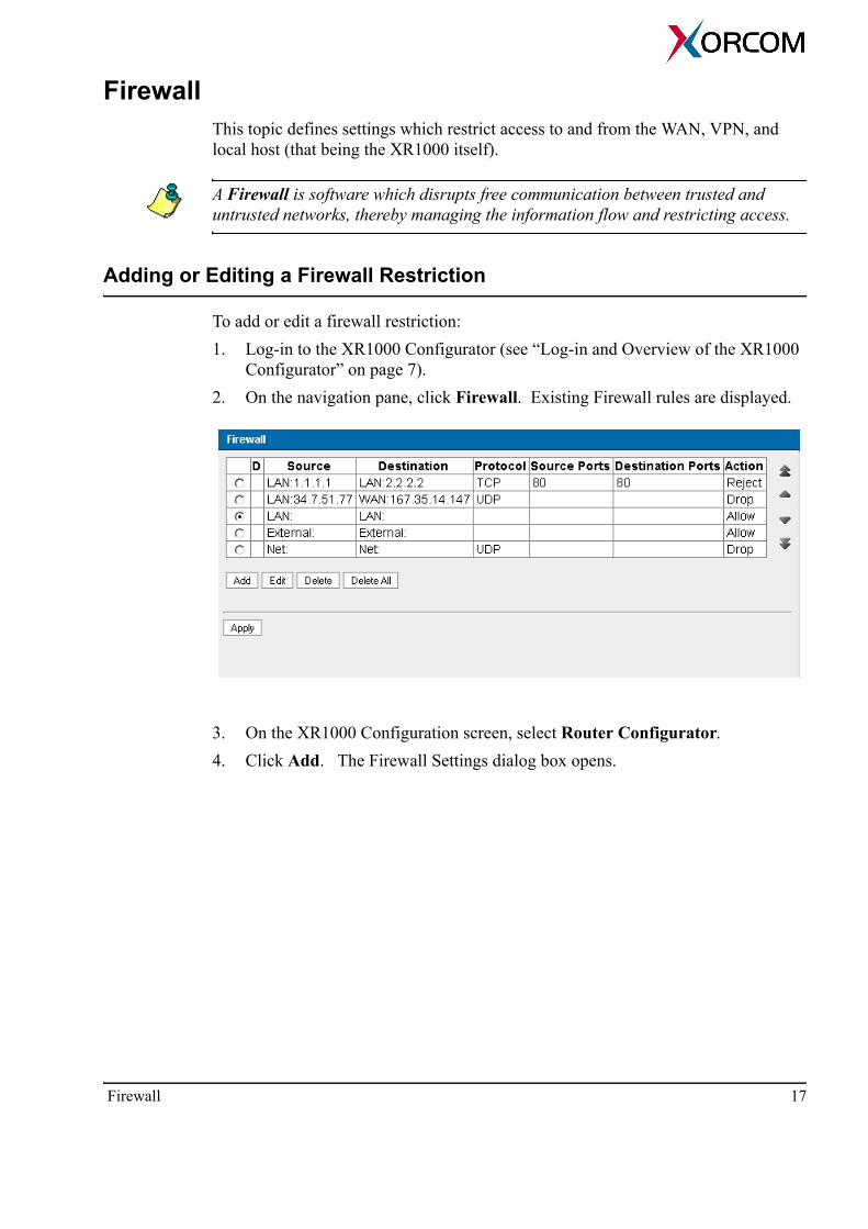
FirewallThis topic defines settings which restrict access to and from the WAN, VPN, and local host (that being the XR1000 itself).
A Firewall is software which disrupts free communication between trusted and untrusted networks, thereby managing the information flow and restricting access.
Adding or Editing a Firewall Restriction
To add or edit a firewall restriction: 1. Log-in to the XR1000 Configurator (see “Log-in and Overview of the XR1000
Configurator” on page 7).2. On the navigation pane, click Firewall. Existing Firewall rules are displayed.
3. On the XR1000 Configuration screen, select Router Configurator. 4. Click Add. The Firewall Settings dialog box opens.
Firewall 17

5. Define the Source connection component of the rule. The Source computer is the computer initiating the contact. Zone From the dropdown list, select the zone to which this restriction will apply. For example, if LAN is selected, the restriction will apply to all computers on the LAN. Address Optionally, enter the IP address of a host from the selected zone to which the restriction will be applied.
6. Select one of the options from the Destination address field. The Destination computer is the computer receiving the contact. Zone From the dropdown list, select the zone to which this restriction will apply. For example, if LAN is selected, the restriction will apply to all computers on the LAN. Address Optionally, enter the IP address of a host from the selected zone to which the restriction will be applied.
7. From the Protocol dropdown list, select the protocol used on the local network. AnyBoth TCP and UDP.
18 XR1000

TCP (Transmission Control Protocol) TCP is one of the two transport protocols in TCP/IP. TCP ensures that a message is sent accurately and in its entirety.UDP (User Datagram Protocol) UDP is the second of the two transport protocols in TCP/IP. For real-time voice and video, there is no time or reason to correct errors, and UDP is used
8. Optionally, if the protocol is defined as TCP or UDP, it is also possible to define port restrictions. If the protocol is defined as Any, it is not possible to define the ports restriction. To define port restrictions:a. Ensure that the protocol is defined as either TCP or UDP. b. Define the Source port numbers. In the common case it may be comma
separated list of numbers and/or ranges. A port range may be defined as <start>:<end>. For example,80,82,20:23,90.To restrict all ports for the selected protocol, leave the Source ports field empty.
c. Define the Destination port numbers. Rules of definition are the same as for the definition of the Source port numbers.
9. There are three types of firewall rules, distinguished by their Action. Select an Action. Allow This rule allows the connection to proceed. Reject This rule rejects the connection immediately and sends a Reject message. Drop This rule allows the connection to be dropped. No message is sent to the remote computer.
10. Click OK. The Firewall Settings dialog box closes.
The firewall will check the rules in an ascending order as they appear in the table.
11. Click the Move up and Move down arrows to align the rules in the order they will be applied. The firewall will check the rules in an ascending order as they appear in the table.
12. Click OK > Apply. 13. To permanently save the changes, click Save Configuration.
Firewall 19

Removing a Firewall Restriction
To remove a firewall restriction: 1. From the Firewall screen, select the radio button beside the restriction to be
removed.
2. Click Delete. 3. Click Apply. 4. To permanently save the changes, click Save Configuration.
20 XR1000
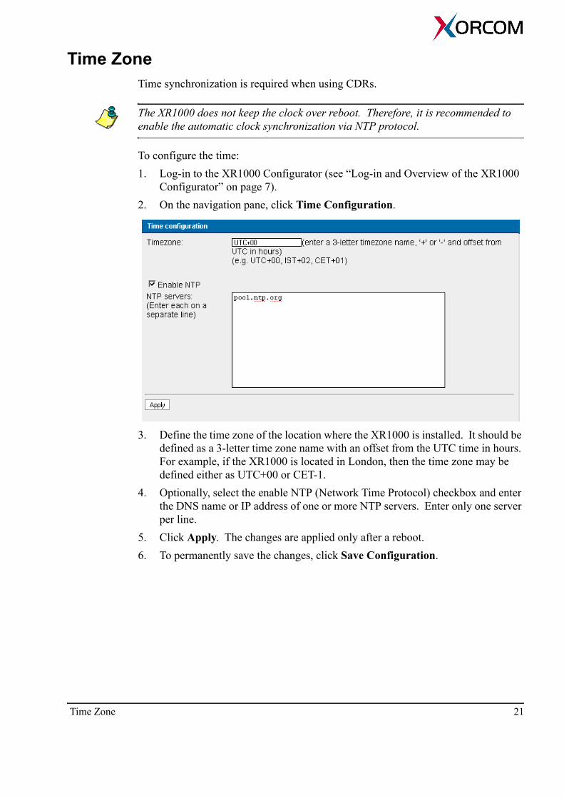
Time ZoneTime synchronization is required when using CDRs.
The XR1000 does not keep the clock over reboot. Therefore, it is recommended to enable the automatic clock synchronization via NTP protocol.
To configure the time: 1. Log-in to the XR1000 Configurator (see “Log-in and Overview of the XR1000
Configurator” on page 7).2. On the navigation pane, click Time Configuration.
3. Define the time zone of the location where the XR1000 is installed. It should be defined as a 3-letter time zone name with an offset from the UTC time in hours. For example, if the XR1000 is located in London, then the time zone may be defined either as UTC+00 or CET-1.
4. Optionally, select the enable NTP (Network Time Protocol) checkbox and enter the DNS name or IP address of one or more NTP servers. Enter only one server per line.
5. Click Apply. The changes are applied only after a reboot.6. To permanently save the changes, click Save Configuration.
Time Zone 21

SMTP Mail ServerUse this procedure to enable the PBX to send voice mail messages as email attach-ments to the PBX users. You have to configure the connection to an SMTP server.
SMTP severs which require TLS (Transport Layer Security) are currently not supported.
To configure the connection to an SMTP server:1. Log-in to the XR1000 Configurator (see “Log-in and Overview of the XR1000
Configurator” on page 7).2. On the navigation pane, click SMTP.
3. Enter the IP address or DNS host name of the SMTP server.4. Enter the port number of the server. The default number is 25.5. Enter the User name and Password required by some SMTP servers for authenti-
cation.6. Click Apply.7. To permanently save the changes, click Save Configuration.
22 XR1000

SyslogTo configure XR1000 to send diagnostic messages to a syslog server:1. Log-in to the XR1000 Configurator (see “Log-in and Overview of the XR1000
Configurator” on page 7).2. On the navigation pane, click Syslog. The Syslog screen is displayed.
3. Select the Enable checkbox.4. Enter the IP address of the Syslog server.5. Enter the UDP port via which the Syslog server will receive messages.6. Click Apply.7. To permanently save the changes, click Save Configuration.
Syslog 23
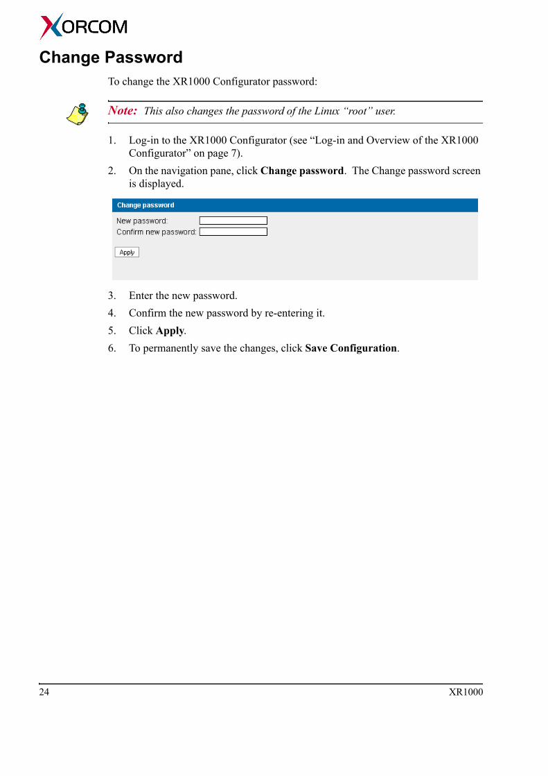
Change PasswordTo change the XR1000 Configurator password:
Note: This also changes the password of the Linux “root” user.
1. Log-in to the XR1000 Configurator (see “Log-in and Overview of the XR1000 Configurator” on page 7).
2. On the navigation pane, click Change password. The Change password screen is displayed.
3. Enter the new password.4. Confirm the new password by re-entering it.5. Click Apply.6. To permanently save the changes, click Save Configuration.
24 XR1000

SECTION 3:
THE MAINTENANCE MENU
The Maintenance menu includes the following:• “View Logs” on page 26• “Backup and Restore” on page 27• “Tune FXO” on page 28• “CDR” on page 30• “System Cleanup” on page 30• “Software Update” on page 31• “Remote Support” on page 32• “Restart the Server” on page 32
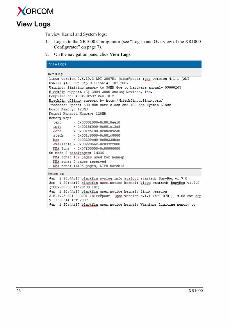
View LogsTo view Kernel and System logs:1. Log-in to the XR1000 Configurator (see “Log-in and Overview of the XR1000
Configurator” on page 7).2. On the navigation pane, click View Logs.
26 XR1000
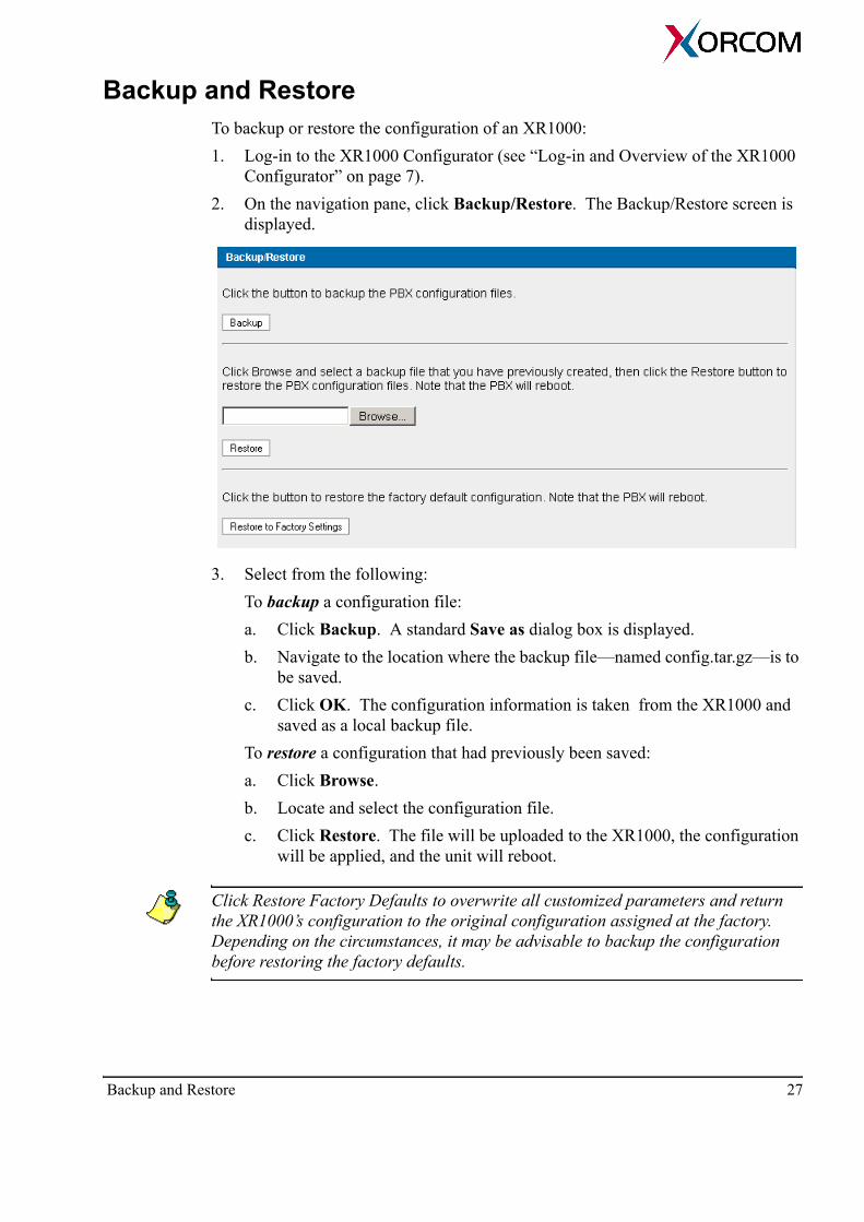
Backup and RestoreTo backup or restore the configuration of an XR1000:1. Log-in to the XR1000 Configurator (see “Log-in and Overview of the XR1000
Configurator” on page 7).2. On the navigation pane, click Backup/Restore. The Backup/Restore screen is
displayed.
3. Select from the following:To backup a configuration file:a. Click Backup. A standard Save as dialog box is displayed.b. Navigate to the location where the backup file—named config.tar.gz—is to
be saved.c. Click OK. The configuration information is taken from the XR1000 and
saved as a local backup file. To restore a configuration that had previously been saved: a. Click Browse.b. Locate and select the configuration file.c. Click Restore. The file will be uploaded to the XR1000, the configuration
will be applied, and the unit will reboot.
Click Restore Factory Defaults to overwrite all customized parameters and return the XR1000’s configuration to the original configuration assigned at the factory. Depending on the circumstances, it may be advisable to backup the configuration before restoring the factory defaults.
Backup and Restore 27
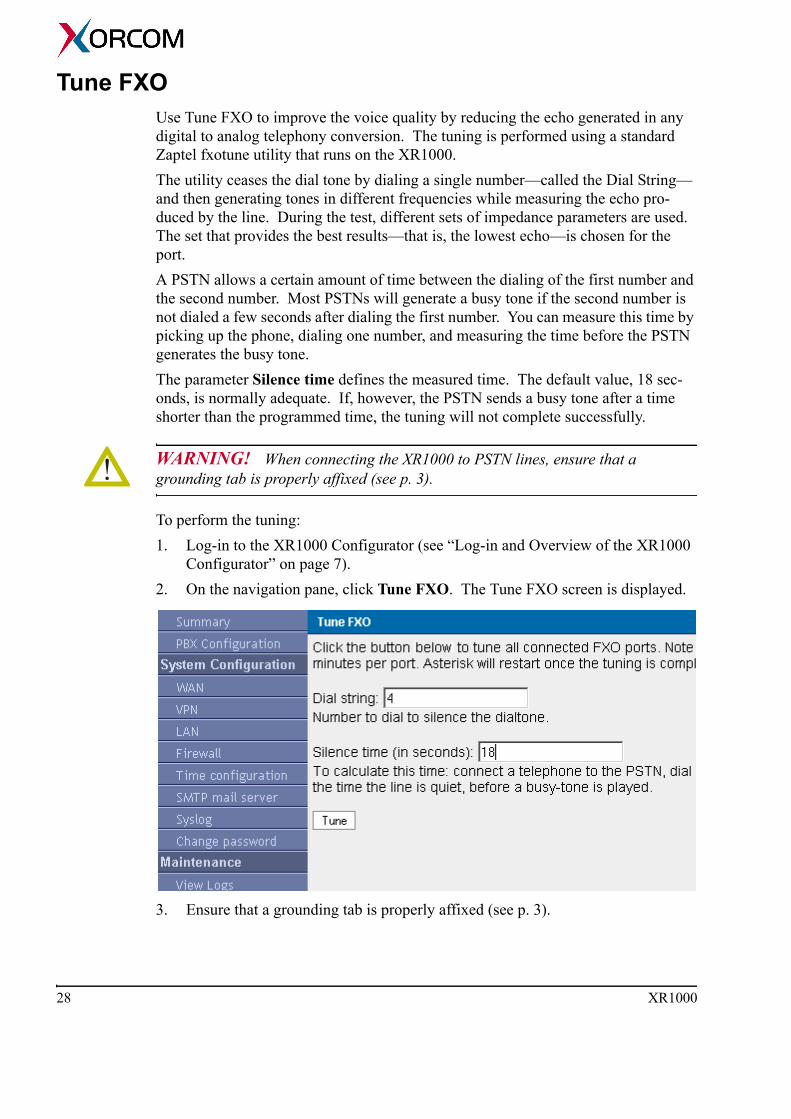
Tune FXO Use Tune FXO to improve the voice quality by reducing the echo generated in any digital to analog telephony conversion. The tuning is performed using a standard Zaptel fxotune utility that runs on the XR1000. The utility ceases the dial tone by dialing a single number—called the Dial String—and then generating tones in different frequencies while measuring the echo pro-duced by the line. During the test, different sets of impedance parameters are used. The set that provides the best results—that is, the lowest echo—is chosen for the port.A PSTN allows a certain amount of time between the dialing of the first number and the second number. Most PSTNs will generate a busy tone if the second number is not dialed a few seconds after dialing the first number. You can measure this time by picking up the phone, dialing one number, and measuring the time before the PSTN generates the busy tone.The parameter Silence time defines the measured time. The default value, 18 sec-onds, is normally adequate. If, however, the PSTN sends a busy tone after a time shorter than the programmed time, the tuning will not complete successfully.
WARNING! When connecting the XR1000 to PSTN lines, ensure that a grounding tab is properly affixed (see p. 3).
To perform the tuning:1. Log-in to the XR1000 Configurator (see “Log-in and Overview of the XR1000
Configurator” on page 7).2. On the navigation pane, click Tune FXO. The Tune FXO screen is displayed.
3. Ensure that a grounding tab is properly affixed (see p. 3).
28 XR1000
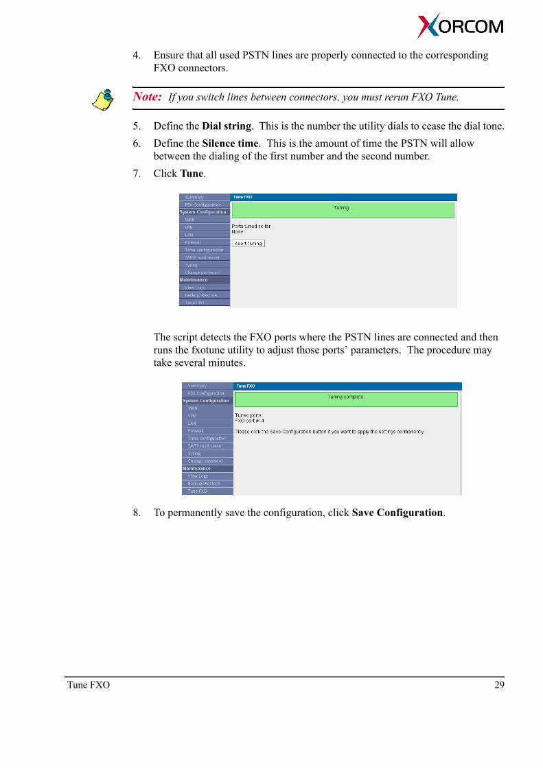
4. Ensure that all used PSTN lines are properly connected to the corresponding FXO connectors.
Note: If you switch lines between connectors, you must rerun FXO Tune.
5. Define the Dial string. This is the number the utility dials to cease the dial tone.6. Define the Silence time. This is the amount of time the PSTN will allow
between the dialing of the first number and the second number. 7. Click Tune.
The script detects the FXO ports where the PSTN lines are connected and then runs the fxotune utility to adjust those ports’ parameters. The procedure may take several minutes.
8. To permanently save the configuration, click Save Configuration.
Tune FXO 29

CDRCall Detail Records (CDR) keep track of a XR1000’s incoming and outgoing calls. Starting from XR1000 software version 0.95, CDR collecting is disabled by default. See “CDR Reader” on page 68 for further details. To review the CDRs, they must first be downloaded.
The records are presented in the comma-separated values (CSV) format.
1. Log-in to the XR1000 Configurator (see “Log-in and Overview of the XR1000 Configurator” on page 7).
2. On the navigation pane, click CDR. The CDR screen is displayed.3. Click Download. 4. Navigate to the location where the CDR file—named Master.csv—is to be
saved.5. Click OK. The CDRs are taken from the XR1000 and saved as a local file. 6. Optionally, click Delete CDRs to delete the records from the XR1000.
System CleanupUse System Cleanup to delete temporary files from the flash drive. Log files, CDRs, and voice mail can be deleted.1. Log-in to the XR1000 Configurator (see “Log-in and Overview of the XR1000
Configurator” on page 7).2. On the navigation pane, click System cleanup. The System cleanup screen is
displayed.3. Select or clear the checkboxes.
There is no confirmation message.
4. Click Cleanup.
30 XR1000

Software UpdateUse the Software Update page to install the latest version of the XR1000 software.
Note: A firmware upgrade does not cause lose of your device configuration. Nevertheless, we recommend that you back-up the configuration before updating.
1. Download the appropriate firmware version file and save it in a folder on your computer. Versions can be downloaded from: http://www.xorcom.com/products/xr1000/xr1000_firmware
2. Reboot the XR1000 (see “Restart the Server” on page 32).3. Log-in to the XR1000 Configurator (see “Log-in and Overview of the XR1000
Configurator” on page 7).4. On the navigation pane, click Software update. The Software update screen is
displayed.5. Click Browse. 6. Locate and select the configuration file. The firmware file name format is:
xr1000-V.VV-YYYYMMDDhhmm.tar.gz
where,V.VV = version numberYYYYMMDDhhmm = year, month, day, hour and minutes when the package was built.
7. Click Update. The update process takes several minutes and may take more time if the update is performed via the Internet. When the version update is completed, the device reboots itself and the LEDs flash. However, there is no message on this page indicating that the update is complete.
Software Update 31

Remote SupportUse this screen to enable a Technical Support engineer to create a RapidTunneling ™ remote SSH connection to your PBX. The connection is possible even when your device is located behind a NAT router and usually it does not require any changes in the router configuration.A Technical Support engineer will prepare and send you by email a file that contains address information and a public encryption key needed for establishing secure com-munication channel from your PBX to a special Technical Support Server. Once the connection is established, the engineer will create an SSH tunnel and access your PBX through that server.
Note: Your unit will be available for remote access only through that special server and only until either the engineer disconnects your PBX from the server or until you reboot the PBX.
In order to enable RapidTunneling ™ communication:1. Save onto your computer the file delivered to you from Xorcom Technical Sup-
port. 2. Connect to the unit with your Internet browser and log in to the system. 3. From the navigation pane, select Remote Support. 4. Click Browse.5. Locate and select the file that you received from Xorcom Technical Support.6. Click Connect. This enables remote connection to your PBX.To break down the RapidTunneling ™ communication tunnel:1. Connect to the unit with your Internet browser and log in to the system. 2. From the navigation pane, select Restart.3. Click Reboot System. This breaks down the remote connection to your PBX.
Restart the ServerUse the Restart screen to restart either the Asterisk PBX software only or to reboot the entire XR1000 system.
32 XR1000
SECTION 4:
PBX CONFIGURATION
Use the XR1000 browser-based PBX Configurator to configure the dial plan fea-tures. This section includes:• “Overview” on page 34• “Adding User Extensions” on page 39• “Enabling Conferencing” on page 42• “Configuring Voicemail” on page 44• “Configuring Call Queues” on page 46• “Adding Service Providers” on page 48• “Calling Rules” on page 52• “Incoming Calls” on page 55• “Voice Menus” on page 57• “Time Based Rules” on page 60• “Call Parking” on page 62• “Ring Groups” on page 64• “Record a Menu” on page 66• “Administrator Monitors and Tools” on page 67• “Options” on page 70
OverviewConfigure PBX functionality using the modified Asterisk GUI supplied with the XR1000. Access PBX services from analog telephones using the special phone num-bers that appear in “Special Phone Numbers for Accessing PBX Service” on page 38.
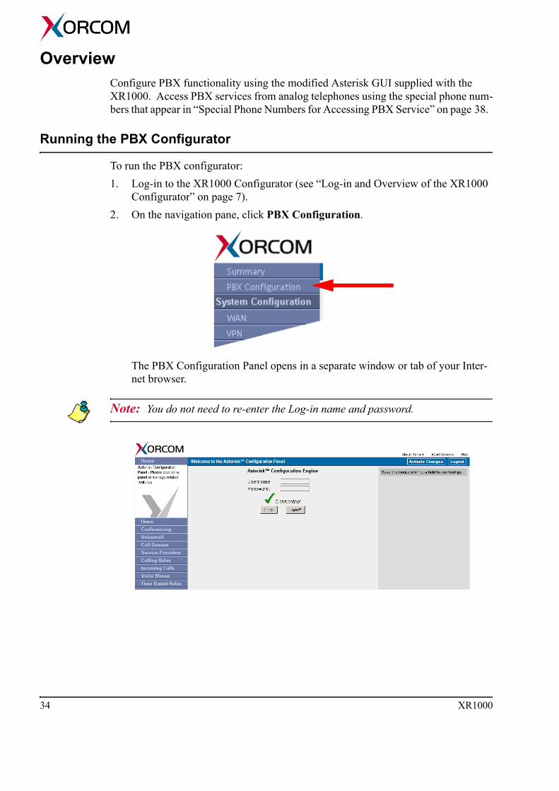
Running the PBX Configurator
To run the PBX configurator:1. Log-in to the XR1000 Configurator (see “Log-in and Overview of the XR1000
Configurator” on page 7).2. On the navigation pane, click PBX Configuration.
The PBX Configuration Panel opens in a separate window or tab of your Inter-net browser.
Note: You do not need to re-enter the Log-in name and password.
34 XR1000

3. We recommend becoming familiar with the following interface elements that appear in the blue title bar:
A B
Principles of Dialing Plan Configuration
For the most part, PBX extensions are configured on the Users screen. There are exceptions—that is, optional extension numbers—that are defined on other screens. For example, when you add a Ring Group (see “Ring Groups” on page 64) you have the option to define a phone number that may be used for dialing to that Ring Group.The PBX communicates with the external world via Service Providers that are defined on the Service Providers screen. Each service provider is actually either an analog (FXO) or a VoIP (SIP or IAX2) trunk.The dialing rules that determine how to dial to a Service Provider are defined on the Calling Rules screen (see “Calling Rules” on page 52). The rules are grouped in Dial Plans. Each PBX extension has a Dial Plan assigned to it. This allows the System Administrator to define different rules and permissions for outward calling for partic-ular extensions. In the following example, there are two Service Providers:
• FXO lines connected to the PSTN• FreeWorld Dialup (FWD) VoIP provider.
Element Explanation
These two arrows (A above) are a Refresh button. Click here to reload the displayed information.
Clicking this button—B above, located in the upper right corner—forces XR1000 to reload the configu-ration files. Note that you must also save the changes on the flash memory—by clicking the Save Configuration button on the System Configuration screen—if you want the changes to be permanent.
Overview 35

The PBX must be configured such that users 401 and 402 will be able to make out-ward calls via both providers and user 403 must be able to make calls only via FWD. User 404 must be able to make internal calls only. 1. First, define both Service Providers in the Service Providers dialog:
2. Then, create three Dial Plans using the Calling Rules screen.Dial Plan 1The first rule requires that you dial 9 and then any number of digits in order to make call via an FXO line. The second rule requires that you dial 8 and then any number of digits in order to make call via FWD.
Dial Plan 2Dial Plan 2 has only one rule which requires that you dial 8 and then any number of digits in order to make call via FWD.
Dial Plan 3This dial plan does not include any rules.
36 XR1000
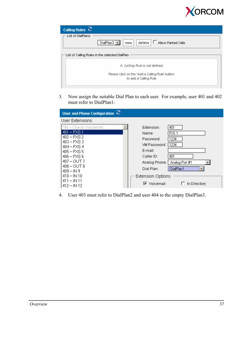
3. Now assign the suitable Dial Plan to each user. For example, user 401 and 402 must refer to DialPlan1:
4. User 403 must refer to DialPlan2 and user 404 to the empty DialPlan3.
Overview 37
Special Phone Numbers for Accessing PBX Service
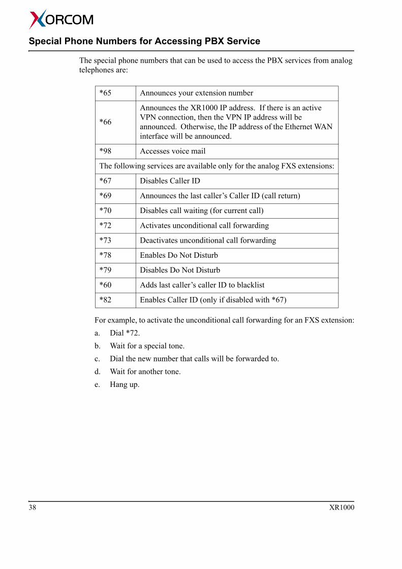
The special phone numbers that can be used to access the PBX services from analog telephones are:
For example, to activate the unconditional call forwarding for an FXS extension:a. Dial *72.b. Wait for a special tone.c. Dial the new number that calls will be forwarded to.d. Wait for another tone.e. Hang up.
*65 Announces your extension number
*66
Announces the XR1000 IP address. If there is an active VPN connection, then the VPN IP address will be announced. Otherwise, the IP address of the Ethernet WAN interface will be announced.
*98 Accesses voice mail
The following services are available only for the analog FXS extensions:
*67 Disables Caller ID
*69 Announces the last caller’s Caller ID (call return)
*70 Disables call waiting (for current call)
*72 Activates unconditional call forwarding
*73 Deactivates unconditional call forwarding
*78 Enables Do Not Disturb
*79 Disables Do Not Disturb
*60 Adds last caller’s caller ID to blacklist
*82 Enables Caller ID (only if disabled with *67)
38 XR1000

Adding User ExtensionsTo add a User Extension:1. Run the PBX Configurator (see “Running the PBX Configurator” on page 34).2. On the navigation pane, click User Extensions. Existing extensions are dis-
played.
3. Click New. 4. Define the following parameters:
Extension Enter the extension assigned to the user. Name Enter the name of the individual assigned to this extension.
Note: The Dial By Name Directory uses this information to route calls.
Password Enter the password used to access voice-mail for the extension. Email Address Enter the email address to which voice-mail received by this extension will be forwarded.
Adding User Extensions 39

Caller ID Enter the Caller ID displayed to the person receiving a call from this extension.
Note: If you use a letter for the Caller ID, the Caller ID will not be displayed on an analog phone since analog phones can display numbers only.
Analog Phone From the dropdown menu, select the analog phone port which this extension will access. Dial Plan From the dropdown menu, select a Dial Plan. Use Dial Plans to configure calling permissions for each PBX extension. The Dial Plan is configured on the Calling Rules screen. Each Dial Plan can include a different set of calling rules.
5. Select or clear the following Extension Options:
Note: It is possible to define simultaneously SIP, IAX and Analog Telephony capabilities for each individual user.
Voice-mail Select this option to create a voice-mail box for the extension.In Directory listing Select this option to include this user in the telephony directory. The telephony directory is referred to by the Asterisk Directory application that allows users to call the PBX extensions by dialing the three first letters of the associated name. It also is needed to configure a Go to Directory as an item in the Voice Menu (see “Voice Menus” on page 57). SIP Select this options when the extension uses the SIP protocol. IAX Select this options when the extension uses the IAX protocol.CTI (Computer Telephony Integration) Select this option to enable users to connect applications to the XR1000 Management Interface. When selected, a Asterisk Management Interface user will automatically be created using the Name and Password defined above.Is Agent When selected, the extension may be a member of a Call Queue (see “Configuring Call Queues” on page 46).Call Waiting When selected, the called user hears a signal if the extension receives a second incoming call. The caller hears the normal ring-back tone and does not get any indication that the called number is engaged. The feature is applicable for the analog PBX extensions only.
40 XR1000

3-Way Calling When selected, the user can dial out to a second phone number thereby creating a 3-way conference call.Can ReinviteThis feature is only applicable if the user has SIP or/and IAX capabilities. When enabled, the Asterisk will perform IP/port re-negotiation and force the call parties to send voice packets directly between them. NATNAT (Network Address Translation) should be enabled when the XR1000 is located on the open Internet and the user is located behind a NAT system. In many cases, selecting NAT helps solve the one-way voice problem when the SIP protocol is used. DTMF ModeDTMF Mode (Dual-tone multi-frequency) defines how DTMF signals are sent during SIP calls. Select one of the following:• rfc2833
Sends DTMFs according to the RFC-2833 (the default value)• info
Sends DTMFs by using SIP INFO messages• inband
Sends DTMFs as regular voice• auto
Sends DTMFs according to the RFC-2833 if the partner supports this method. If not, they are sent as inband.
6. Define the codec list to be used for VoIP calls.
Note: Codec types are voice compression/decompression (CoDec) methods. The Codec type is negotiated with the remote VoIP device per call.
WARNING! The XR1000 must have at least one enabled codec that is common with the remote VoIP device. Otherwise, the call will be rejected.
7. To permanently save the changes, return to the System Configuration browser-window, and click Save Configuration.
Adding User Extensions 41

Enabling Conferencing Conferencing allows creation of phone-calls “Bridges” that include more than 3 par-ties. To create a new phone-call Bridge:1. Run the PBX Configurator (see “Running the PBX Configurator” on page 34).2. On the navigation pane, click Conferencing. Existing Conference Bridges are
displayed.
3. Click New. 4. Define the following parameters: 5. Enter the Extension dialed to access the Bridge. 6. Enter the Password settings
PIN Code This is the number entered by users to participate in the conference.Administrator PIN Code This is the number entered by the moderator of the conference to open the conference bridge.
7. Select or clear the following Conference Room options:Play hold music for first caller When selected, music is played for the first caller entering the conference. The music ends when a second caller joins. Enable caller menu When selected, users can access the Conference Bridge Menu by pressing the asterisk (*) key.
42 XR1000

Announce callers When selected, new callers are identified when they arrive.Quiet ModeThis feature confines participants to listen-only access. For example, by creating two access points, one group can be confined to Quiet Mode while the speaker lectures. Wait for Marked User Use this feature to confine all participants to Quiet Mode until a participant—called the Marked User and using a unique extension—arrives. After the Marked User arrives, the audio is activated and the other participants can speak to each other. Set Marked User Select this option to designate the Marked User’s extension.
8. Optionally, test the changes.9. To permanently save the changes, return to the System Configuration browser-
window, and click Save Configuration.
Enabling Conferencing 43

Configuring VoicemailTo configure voice-mail:1. Run the PBX Configurator (see “Running the PBX Configurator” on page 34).2. Optionally, if you will use voice-mail-to-email functionality, configure SMTP
mail server parameters (see “SMTP Mail Server” on page 22).3. On the navigation pane, click Voicemail. Voicemail Configuration page is dis-
played.
4. Enter the Extension for checking messages. This is the extension Users call to access their voice-mail. By default, the XR1000 uses extension *98.
5. Select or clear the Attach recordings to email checkbox. When selected, voice-mail is sent to the users email address.
6. Enter a Max greeting length. This specifies the maximum duration of the recorded voice-mail greeting.
7. Select or clear the Dial "0" for Operator checkbox. When selected, callers can can transfer to the operator by pressing 0. If cleared, pressing 0 is ignored.
8. Configure the Message Options:Message Format From the dropdown menu, select the format in which messages are delivered by email.
44 XR1000
Maximum Messages per Folder Enter the maximum number of messages allowed in a voice-mail box. The default maximum is 10.Maximum Message Time Enter the maximum allowed duration of a message. The maximum allowed is two minutes.Minimum Message Time Enter the minimum allowed duration of a message. The default value is zero.
9. Select or clear the following Playback Options:Send Messages by email Only When selected, notification of messages is by email only. Voice messages are not saved. Make sure that the SMTP server is configured (see “SMTP Mail Server” on page 22).Say Message Caller-ID When selected, the caller ID is announced before the voice-mail message is played. Say Message Duration When selected, the duration of the message is announced before the voice-mail message is played.Play Envelope When selected, the date, time, and caller ID of the message is announced before the voice-mail message is played.Allow Users to Review When selected, callers can review and edit their message before it is saved.
10. Optionally, test the changes.11. To permanently save the changes, return to the System Configuration browser-
window, and click Save Configuration.12. Enable Voicemail and define a Voicemail password for each user that will have a
voice mail box (see “Adding User Extensions” on page 39).
Configuring Voicemail 45

Configuring Call QueuesA call queue stacks incoming calls in the order they are received. Calls are allocated to operators according to the queue settings. To configure a Call Queue:1. Run the PBX Configurator (see “Running the PBX Configurator” on page 34).2. Ensure that Is Agent is enabled on the extension (see “Is Agent” on page 40). 3. Configure the agent’s log-in settings (see “Options” on page 70).4. On the navigation pane, click Call Queues. The Call Queues page is displayed
and existing Queues are listed on the left.
5. Either:• click New to configure a new Call Queue• select an existing Call Queue to edit the configuration
6. In the Queue field, enter the Queue’s extension number.7. In the Full Name field, enter a descriptive name.8. From the Strategy dropdown menu, select a call routing option:
Ring All When a new call is received, this option rings every agent who is not on an active call. Round Robin This option allocates new calls to agents in turn.
46 XR1000
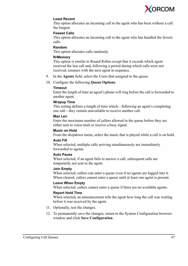
Least Recent This option allocates an incoming call to the agent who has been without a call the longest.Fewest Calls This option allocates an incoming call to the agent who has handled the fewest calls.Random This option allocates calls randomly.RrMemory This option is similar to Round Robin except that it records which agent received the last call and, following a period during which calls were not received, resumes with the next agent in sequence.
9. In the Agents field, select the Users that assigned to the queue.10. Configure the following Queue Options:
Timeout Enter the length of time an agent’s phone will ring before the call is forwarded to another agent.Wrapup Time This setting defines a length of time which—following an agent’s completing one call—they remain unavailable to receive another call.Max Len Enter the maximum number of callers allowed in the queue before they are either sent to voice-mail or receive a busy signal. Music on Hold From the dropdown menu, select the music that is played while a call is on hold.Auto Fill When selected, multiple calls arriving simultaneously are immediately forwarded to agents. Auto Pause When selected, if an agent fails to answer a call, subsequent calls are temporarily not sent to the agent. Join Empty When selected, callers can enter a queue even if no agents are logged into it. When cleared, callers cannot enter a queue until at least one agent is present.Leave When Empty When selected, callers cannot enter a queue if there are no available agents. Report Hold Time When selected, an announcement tells the agent how long the call was waiting before it was received by the agent.
11. Optionally, test the changes.12. To permanently save the changes, return to the System Configuration browser-
window and click Save Configuration.
Configuring Call Queues 47
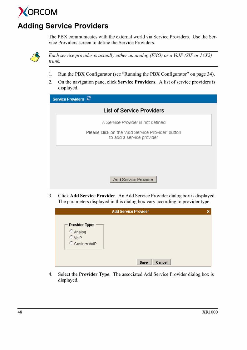
Adding Service Providers The PBX communicates with the external world via Service Providers. Use the Ser-vice Providers screen to define the Service Providers.
Each service provider is actually either an analog (FXO) or a VoIP (SIP or IAX2) trunk.
1. Run the PBX Configurator (see “Running the PBX Configurator” on page 34).2. On the navigation pane, click Service Providers. A list of service providers is
displayed.
3. Click Add Service Provider. An Add Service Provider dialog box is displayed. The parameters displayed in this dialog box vary according to provider type.
4. Select the Provider Type. The associated Add Service Provider dialog box is displayed.
48 XR1000

Analog Select Analog to define the analog ports that have access to this service provider. The dialog box displays the available analog ports. Select one or more analog ports. VoIP Select a VoIP service provider from a list of pre-configured providers and enter your user name and password. Custom VoIP Select Custom VoIP to customize a VoIP definition. Then, enter the following:
• Comment Enter a distinct and identifiable comment, such as the name of the custom VoIP definition.
• Protocol Specify either the IAX or the SIP protocol.
• Register Select Register to register the IP address with the service provider.
• Host Enter the IP address or DNS host name of the service provider.
• Username Enter the user name associated with your provider account.
• Password Enter the password associated with your provider account.
5. Click Save. The new service provider appears on the list of providers on the Service Providers page.
6. If necessary, from the Options dropdown menu, refine the configuration. Some options are available only for specific types of service providers. Codecs All codecs are allowed by default. To disable a codec: a. From the Options dropdown menu, select Codecs. The Codec Preferences
screen is displayed.
Adding Service Providers 49
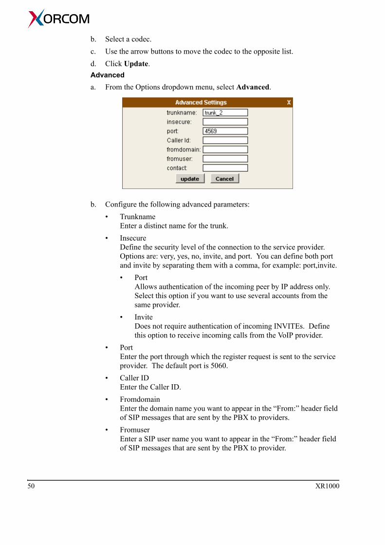
b. Select a codec. c. Use the arrow buttons to move the codec to the opposite list. d. Click Update.Advanced a. From the Options dropdown menu, select Advanced.
b. Configure the following advanced parameters:• Trunkname
Enter a distinct name for the trunk.• Insecure
Define the security level of the connection to the service provider. Options are: very, yes, no, invite, and port. You can define both port and invite by separating them with a comma, for example: port,invite.• Port
Allows authentication of the incoming peer by IP address only. Select this option if you want to use several accounts from the same provider.
• Invite Does not require authentication of incoming INVITEs. Define this option to receive incoming calls from the VoIP provider.
• Port Enter the port through which the register request is sent to the service provider. The default port is 5060.
• Caller ID Enter the Caller ID.
• Fromdomain Enter the domain name you want to appear in the “From:” header field of SIP messages that are sent by the PBX to providers.
• Fromuser Enter a SIP user name you want to appear in the “From:” header field of SIP messages that are sent by the PBX to provider.
50 XR1000

• Contact Enter a SIP user name you want to appear in the “Contact:” header field of SIP messages that are sent by the PBX to provider.
c. Click Update.7. Click Activate Changes. The changes are immediately available. 8. Optionally, test the changes.9. To permanently save the changes, return to the System Configuration browser-
window and click Save Configuration.
Adding Service Providers 51
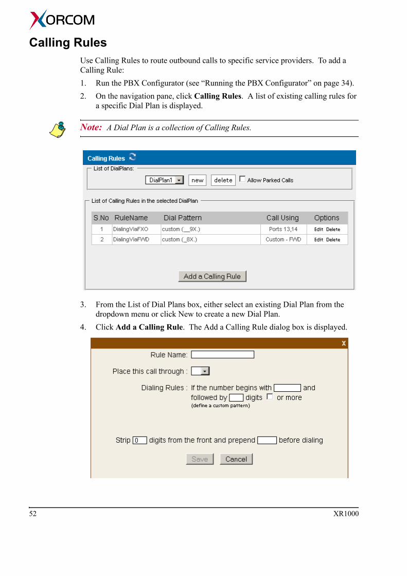
Calling Rules Use Calling Rules to route outbound calls to specific service providers. To add a Calling Rule:1. Run the PBX Configurator (see “Running the PBX Configurator” on page 34).2. On the navigation pane, click Calling Rules. A list of existing calling rules for
a specific Dial Plan is displayed.
Note: A Dial Plan is a collection of Calling Rules.
3. From the List of Dial Plans box, either select an existing Dial Plan from the dropdown menu or click New to create a new Dial Plan.
4. Click Add a Calling Rule. The Add a Calling Rule dialog box is displayed.
52 XR1000

5. Define the following parameters:Rule Name Enter a descriptive name.Place this Call Through Select the service provider to which the rule applies.Dialing Rules This sentence defines the phone number that the rule is applied to. Enter numbers in the fields. In the following example, calls to West Virginia are affected:
Alternatively, you can click define a custom pattern. The Custom Pattern field is displayed.
In the Custom Pattern field, define your own pattern using the following rules:
Calling Rules 53

• the pattern may consists of digits and special wildcard characters• if the pattern contains at least one wildcard character then it must have the
underscore ('_') character in the beginning• wildcard character X matches any digit from 0-9• wildcard character Z matches any digit from 1-9• wildcard character N matches any digit from 2-9• wildcard character dot (.) matches one or more any charactersFor example:
• Pattern: _9054XXXXXXX Matches any phone number that has 9054 at the beginning and then 7 digits.
• Pattern: _9054. Matches any phone number that has 9054 at the beginning and the one or more other digits.
Detailed description of the phone number patterns you can find at: http://www.voip-info.org/wiki/index.php?page=Asterisk+Dialplan+Patterns
WARNING! Incorrect building of the dialing rules may cause call failures while dialing from the analog phones. See “FXS/FXO Channel Related Issues” on page 75 in the Troubleshooting section for further details.
Strip / PrependThis sentence defines the changes that are made to the original number. Strip defines the quantity of numbers that are deleted from the beginning of the original number. Prepend defines digits that added to the beginning of the number after the strip is complete.
6. Click Save.7. Click Activate Changes. The changes are immediately available. 8. Optionally, test the changes.9. To permanently save the changes, return to the System Configuration browser-
window and click Save Configuration.
54 XR1000
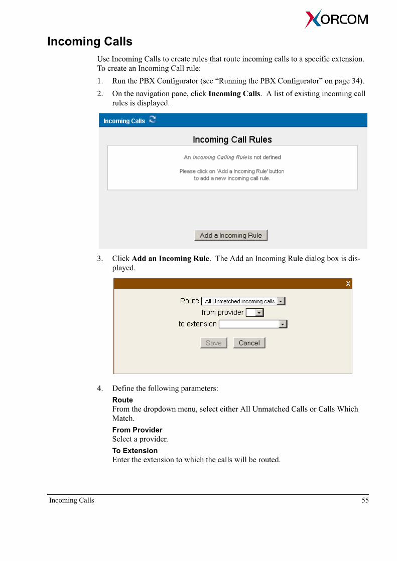
Incoming Calls Use Incoming Calls to create rules that route incoming calls to a specific extension. To create an Incoming Call rule: 1. Run the PBX Configurator (see “Running the PBX Configurator” on page 34).2. On the navigation pane, click Incoming Calls. A list of existing incoming call
rules is displayed.
3. Click Add an Incoming Rule. The Add an Incoming Rule dialog box is dis-played.
4. Define the following parameters:Route From the dropdown menu, select either All Unmatched Calls or Calls Which Match.From Provider Select a provider. To Extension Enter the extension to which the calls will be routed.
Incoming Calls 55

5. Click Save.6. Click Activate Changes. The changes are immediately available. 7. Optionally, test the changes.8. To permanently save the changes, return to the System Configuration browser-
window and click Save Configuration.
56 XR1000
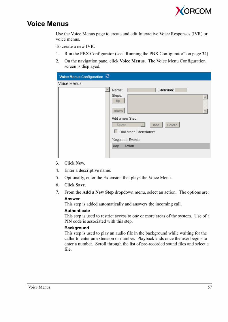
Voice Menus Use the Voice Menus page to create and edit Interactive Voice Responses (IVR) or voice menus. To create a new IVR:1. Run the PBX Configurator (see “Running the PBX Configurator” on page 34).2. On the navigation pane, click Voice Menus. The Voice Menu Configuration
screen is displayed.
3. Click New. 4. Enter a descriptive name.5. Optionally, enter the Extension that plays the Voice Menu.6. Click Save. 7. From the Add a New Step dropdown menu, select an action. The options are:
Answer This step is added automatically and answers the incoming call.Authenticate This step is used to restrict access to one or more areas of the system. Use of a PIN code is associated with this step.Background This step is used to play an audio file in the background while waiting for the caller to enter an extension or number. Playback ends once the user begins to enter a number. Scroll through the list of pre-recorded sound files and select a file.
Voice Menus 57
Record your own message using the “Record a Menu” screen (see “Record a Menu” on page 66). For example: “Hello. Thank you for calling ABC company. For technical support dial 1, for R&D dial 2.”
Busytone Select the Busytone option if there is a step in the process at which a busy signal should be played. Congestion Select the Congestion option if there is a step in the process at which a Congestion signal should be played. Digit Timeout Use the Digit Timeout option to set the maximum amount of time allowed between key presses. If a full extension is not entered in the specified time, the entry will be considered invalid. DISA Use the DISA option to allow callers from outside the system access to an internal dial tone and thereby place calls from within the system. A passcode is required.Response Timeout If a caller does not enter a response with the time specified in this field, the call will terminate. Playback This option plays a selected sound file. However, this option does not listen for a KeyPress event, and proceeds to the next step in the list. Wait This option pauses the execution of steps in the voice menu list for the number of seconds specified.WaitExten This option gives a caller a specified amount of time to enter an extension. Goto Menu This option sends a caller to a specified voice menu. Goto Directory This option sends a caller to the system phone directory. This gives the user the chance to select a user name from the directory.Goto Extension This option sends a caller to a specified extension. Select the extension from the available list. Dial RingGroup This option dials a specified RingGroup. Hangup This option ends the call.
58 XR1000

8. Select or clear the Dial Other Extensions checkbox. When selected, the user can exit the menu selections and dial an extension within the system.
9. Define the Keypress Event actions for digits 0–9, *, #, t, and i.
Note: We recommend not using the t key and i key for specific actions. The action associated with the t key should be the action if a user response has timed-out. The action associated with the i key should be the action if a user makes an invalid entry.
The options are: Disabled The key is disabled. Goto Menu Pressing a key assigned this option transfers the caller to a specific menu.Goto Extension Pressing a key assigned this option transfers the caller to a specific extension. For example, you can define that if the caller pressed 1 then the PBX must connect the caller to extension 1734.Custom Use this option to define calling to an Asterisk application or an AGI script. A strong knowledge of Asterisk configuration options is required to use this option.Hangup Pressing a key assigned this option ends the call. Play Invalid Pressing a key assigned this option tells the caller that they have made an invalid entry.
10. Click Save.11. Click Activate Changes. The changes are immediately available. 12. Optionally, test the changes.13. To permanently save the changes, return to the System Configuration browser-
window and click Save Configuration.
t = time out This is an event that occurs when the user did not dial a digit during a timeout that may be defined, for example, in the WaitExten action step.
i = invalid This is an event that occurs when the user dialed a keypress event digit that has not been configured.
Voice Menus 59

Time Based RulesUse Time Based Rules to define the route of incoming calls. Rules can be created based on the calendar and the time of day. To create a new Time Based Rule:1. Run the PBX Configurator (see “Running the PBX Configurator” on page 34).2. On the navigation pane, click Time Based Rule. The Time Based Rules screen
is displayed.
3. Click New Time Rule. The Add New Time Rule dialog box is displayed.
4. Enter a descriptive name for the new rule.5. Enter the Time and Date Conditions:
Start Time / End TimeThe rule is applied beginning from the hour selected from Start Time dropdown menus. The rule is canceled at the hour selected from the End Time dropdown menus.
60 XR1000

Start Day / End DayThe rule is applied beginning from the day of the week selected from Start Day dropdown menu. The rule is canceled on the day of the week selected from the End Day dropdown menu. Start Date / End Date The rule is applied beginning from the date of the month selected from Start Date dropdown menu. The rule is canceled at the date of the month selected from the End Date dropdown menu. Start Month / End Month The rule is applied beginning from the month selected from Start Month dropdown menu. The rule is canceled at the hour selected from the End Month dropdown menu.
6. Using the dropdown menus, enter the Destination parameters:If time matchesIf time did not match
7. Click Save. The Add New Time Rule dialog box closes and focus returns to the Time Based Rules screen.
8. Click Activate Changes. The changes are immediately available. 9. Optionally, test the changes.10. To permanently save the changes, return to the System Configuration browser-
window and click Save Configuration.
Time Based Rules 61
Call ParkingCall Parking places a call on hold such that it can be taken off hold from another extension.
Defining Call Parking Extensions
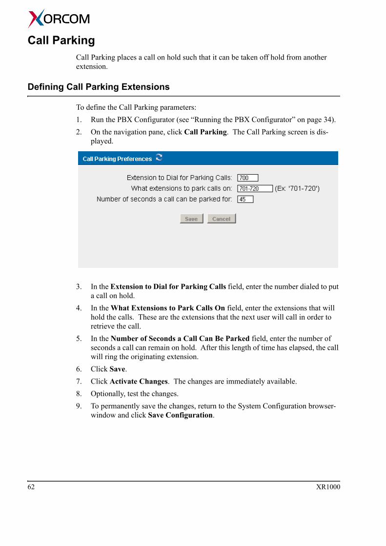
To define the Call Parking parameters: 1. Run the PBX Configurator (see “Running the PBX Configurator” on page 34).2. On the navigation pane, click Call Parking. The Call Parking screen is dis-
played.
3. In the Extension to Dial for Parking Calls field, enter the number dialed to put a call on hold.
4. In the What Extensions to Park Calls On field, enter the extensions that will hold the calls. These are the extensions that the next user will call in order to retrieve the call.
5. In the Number of Seconds a Call Can Be Parked field, enter the number of seconds a call can remain on hold. After this length of time has elapsed, the call will ring the originating extension.
6. Click Save.7. Click Activate Changes. The changes are immediately available. 8. Optionally, test the changes.9. To permanently save the changes, return to the System Configuration browser-
window and click Save Configuration.
62 XR1000
Using Call Parking
Call Parking can be executed using either an analog or VoIP phone. • Analog phone
Press the flash button, or quickly click the hook switch. Then, wait for a dial tone and dial the extension.
• VoIP Phone The method using a VoIP phone will vary depending on the phone. In general, initiate the transfer, dial the call parking extension, then complete the transfer (such as by click send).
In both cases, the XR1000 will announce a number. This is the number that must be entered to retrieve the call. To retrieve the call, pickup a phone and dial the parking number.
Note: To park a call, use attended transfer functions. Using a blind transfer function will not provide the parking number to the person parking the call.
Call Parking 63

Ring Groups Use Ring Groups to simultaneously (or in a ring order) ring a group of phones. To create a new ring group:1. Run the PBX Configurator (see “Running the PBX Configurator” on page 34).2. On the navigation pane, click Ring Groups. The Ring Groups screen is dis-
played.
3. Click New Ring Group. The Add Ring Group dialog box is displayed.
4. Enter a distinctive name for the group.5. From the Strategy dropdown menu, select either:
Ring All All phones in the defined group ring at the same time.Ring Order Phones ring in a sequence determined by the order of the users or trunks in the group.
64 XR1000
6. Select the members of the ring group:a. From the Available Channels list, click on a user extension or trunk.b. Click the left arrow. The extension is moved to Ring Group Members list.c. Repeat the process for additional channels.
7. Optionally, in the Extension for this Ring Group field, enter an extension that can be dialed to ring all members of the group.
8. Enter the number of seconds that each phone should ring.9. Select an action that occurs if no one answers the call.10. Click Save.11. Click Activate Changes. The changes are immediately available. 12. Optionally, test the changes.13. To permanently save the changes, return to the System Configuration browser-
window and click Save Configuration.
Ring Groups 65

Record a Menu Use the Record a Menu screen to record a custom menu prompts to be used in a Voice Menu. Recording are made using a telephone.To record a new voice menu option:1. Run the PBX Configurator (see “Running the PBX Configurator” on page 34).2. On the navigation pane, click Record a Menu. The Record a Menu screen is
displayed.
3. Click New. The Record a New Voice Menu dialog box is displayed.
4. Enter a distinctive name for the new voice menu.5. From the Extension Used for Recording dropdown menu, select the extension
the user will use for recording the prompt. This is the phone-extension referred to in step number 7.
6. Click Record. The PBX will ring to the defined extension and prompt you to start recording of your messages.
7. Pick up the phone and record the messages. 8. Hang-up the phone. The new recorded messages are available from the Voice Menu (see “Voice Menus” on page 57).
66 XR1000
Administrator Monitors and ToolsThe XR1000 PBX Configurator includes a set of monitors and tools.
Active Channels
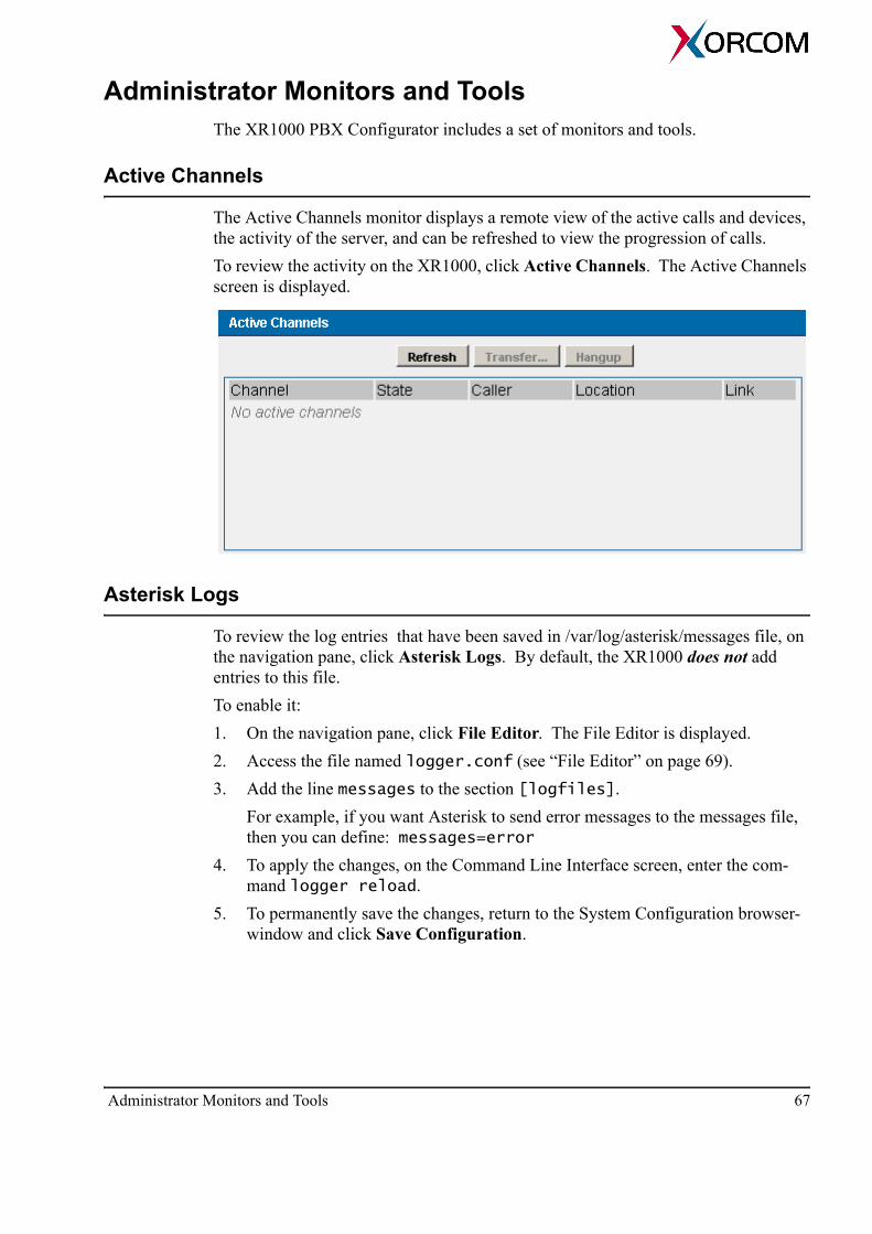
The Active Channels monitor displays a remote view of the active calls and devices, the activity of the server, and can be refreshed to view the progression of calls. To review the activity on the XR1000, click Active Channels. The Active Channels screen is displayed.
Asterisk Logs
To review the log entries that have been saved in /var/log/asterisk/messages file, on the navigation pane, click Asterisk Logs. By default, the XR1000 does not add entries to this file. To enable it:1. On the navigation pane, click File Editor. The File Editor is displayed. 2. Access the file named logger.conf (see “File Editor” on page 69). 3. Add the line messages to the section [logfiles].
For example, if you want Asterisk to send error messages to the messages file, then you can define: messages=error
4. To apply the changes, on the Command Line Interface screen, enter the com-mand logger reload.
5. To permanently save the changes, return to the System Configuration browser-window and click Save Configuration.
Administrator Monitors and Tools 67
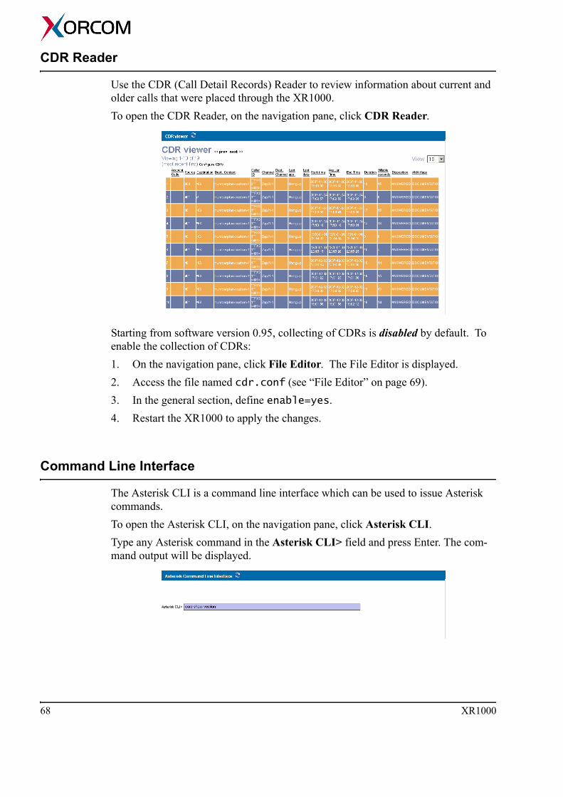
CDR Reader
Use the CDR (Call Detail Records) Reader to review information about current and older calls that were placed through the XR1000. To open the CDR Reader, on the navigation pane, click CDR Reader.
Starting from software version 0.95, collecting of CDRs is disabled by default. To enable the collection of CDRs:1. On the navigation pane, click File Editor. The File Editor is displayed. 2. Access the file named cdr.conf (see “File Editor” on page 69). 3. In the general section, define enable=yes. 4. Restart the XR1000 to apply the changes.
Command Line Interface
The Asterisk CLI is a command line interface which can be used to issue Asterisk commands.To open the Asterisk CLI, on the navigation pane, click Asterisk CLI. Type any Asterisk command in the Asterisk CLI> field and press Enter. The com-mand output will be displayed.
68 XR1000

File Editor
Use the File Editor to edit any Asterisk configuration file and to create a new config-uration file. Usually, the File Editor is used by advanced Asterisk users.1. To open the File Editor, on the navigation pane, click File Editor. The File Edi-
tor page is displayed.2. Expand the Config File dropdown menu.
3. Select a file. The file is displayed. This may take a few seconds.
4. To edit a section, click within the section. That section’s background color turns blue.
5. Make changes within the blue area and click Save.6. Optionally, to add a new section, click Add Context.7. To permanently save the changes, return to the System Configuration browser-
window and click Save Configuration.
Administrator Monitors and Tools 69

Options Use the Admin Settings screen to define settings which apply to the entire VoIP net-work.
Note: The words (Show Advanced Options) appear on the blue title bar. This is a button that, when clicked, opens a dropdown menu entitled Goto: in the upper-right corner. This is displayed in the following picture:
The dropdown menu includes configuration options such as Global SIP Settings, Global IAX settings etc. In most cases, these do not need changed.
1. Run the PBX Configurator (see “Running the PBX Configurator” on page 34).2. On the navigation pane, click Options. The Options screen is displayed.
70 XR1000
3. Define the Local Extension Settings:Local Extensions areFrom the dropdown menu, select the quantity of numbers—or, if AlphaNumeric is enabled, numbers and letters—that a user has to press to connect to an extension.First Extension NumberExtension numbers are sequential. Enter the first number of the sequence.Operator ExtensionEnter the extension number pressed to access the network’s operator.Allow … multiple extensionsMany analog phones can support more than one extension number. When selected, an analog telephone can be assigned several extension numbers. Allow … AlphaNumericWhen selected, users of SIP or IAX can connect using extensions with letters.
4. Define the Agent Login Settings: Agent Login ExtensionThis is an extension used by agents to log-in to a specific queue.Agent Callback Login ExtensionThis is the same as the Agent Login Extension except that you do not have to remain on the line. It is the extension to be dialed for the Agents to log-in to the queues they are apart of.Agent LogoutIn case of Callback Login, to log-out, dial the log-in extension and following the voice prompts.
5. Define the Default Settings for a New User:Is AgentWhen selected, every new user is also an Agent and may be a member of a Call Queue. In DirectoryWhen selected, new users are automatically added to the directory.SIPWhen selected, SIP is the default protocol used for phone calls.Call WaitingWhen selected, the Call Waiting feature is enabled for new users. VoicemailWhen selected, Voicemail is enabled for new users.CTIWhen selected, CTI (Computer Telephone Integration) is enabled for new users. CTI combines data with voice systems thereby enhancing telephone services. For example, automatic number identification (ANI) allows a caller’s records to be retrieved from the database while the call is routed to the appropriate party.
Options 71
IAXWhen selected, IAX (Inter-Asterisk Exchange) is the default protocol used for phone calls. IAX is the proprietary Asterisk protocol used to initiate calls and send the data. 3-way CallingWhen selected, new users can establish 3-way calls. During a 3-way call, a user can talk with two people at the same time.VoiceMail PasswordDefine the password a user enters in order to retrieve their voicemail.
6. Click Save.7. Click Activate Changes. The changes are immediately available. 8. Optionally, test the changes.9. To permanently save the changes, return to the System Configuration browser-
window and click Save Configuration.
72 XR1000

SECTION 5:
SUPPORT AND TROUBLESHOOTING
This section includes:• “Rescue, Restore, and Reflashing Firmware” on page 74• “Troubleshooting” on page 75• “PBX Configuration Internals” on page 82• “XR1000 Configuration Tips” on page 86• “Cables Pin Out” on page 90
Rescue, Restore, and Reflashing FirmwareIn certain circumstances, you might want to restore the factory default configuration or the default password for the web-based configurator. You will also want to reflash the firmware after a severe system crash, for example, if the device was switched off during the normal firmware update (see “Software Update” on page 31).
WARNING! The Restore button returns the configuration to factory default. Consider backing-up your configuration (see “Backup and Restore” on page 27) before using the Restore button.
The rear panel of the XR1000 box has a RESCUE button and a RESTORE button. They function as follows:• Depress the RESTORE button for 5 seconds to reset the configuration to the fac-
tory settings.• Depress the RESCUE button for 5 seconds to reset the password to its default
value: 123456.To reflash the firmware:1. Download a firmware file onto your computer. The latest firmware version can
be downloaded from: http://www.xorcom.com/products/xr1000/xr1000_firmware
2. Unplug the unit.3. Using a tooth-pick, depress the RESCUE button and—while the button is
depressed—plug in the unit’s power.4. After 5 seconds, release the RESCUE button.
The unit will restart in the rescue mode. IP address 10.0.0.1 is automatically assigned to the WAN interface.
5. Connect to the unit’s WAN interface from another computer. There are several ways of connecting:• Connect the device’s WAN RJ-45 connector and your computer to a stand-
alone Ethernet hub or switch.• If 10.nnn.nnn.nnn IP addresses are not used in your office network, then
you can connect the device and computer to the same LAN subnet.• Connect your computer by using an Ethernet cross-cable.
6. Set the computer’s IP address to 10.0.0.100, subnet-mask to 255.255.255.0 and default gateway to 10.0.0.1.
7. Start a Firefox browser and enter 10.0.0.1 in the address field. The XR1000 rescue screen will be displayed.
8. Choose the firmware file that was previously stored on your computer and update the XR1000.When the update process is finished, the XR1000 will automatically reboot.
74 XR1000

TroubleshootingPlease send your suggestions and wish list to [email protected] and we will be glad to contact you and discuss your needs.For additional support and updated information, visit our web site. To open a support ticket, please use the form available at:
http://www.xorcom.com/static/support-form.html Our technical support will contact you.
Common PBX Configuration Issues
How can I define the number of times the phone rings before the call is for-warded to the voice mail? 1. Using any standard File Editor, open the file named extensions.conf.2. Go to context [macro-stdexten]. The first line in the context looks like
the following:exten=s,1,Dial(${ARG2},20)
where, 20 is the timeout (in seconds) that defines how long the PBX must try to connect to an FXS or IP extension (SIP/IAX) before it forwards the call to the voice mail service.
3. Change the timeout value.4. Save and close the file.
FXS/FXO Channel Related Issues
How can I increase the time the Asterisk waits for the next digit when I'm dial-ing from an FXS extension?Very frequently, PBX users do not complete dialing the phone number before the PBX starts to make call. Please be aware of the Asterisk inter-digit timeout handling algorithm for the Zaptel devices:
a. Asterisk waits 16 seconds for the first digit. b. If there is no ambiguous match, Asterisk waits 8 seconds for the next digit. c. If there is an ambiguous match, Asterisk waits 3 seconds for the next digit.
Those time-outs are hard-coded and cannot be changed in the Asterisk configuration files.
Troubleshooting 75

Following is an example. You have defined two patterns each of which ends with a dot. The first pattern is _9X. — the “x” is followed by a dot. The second pattern is
_90044X. The Asterisk user dials 900-44-208-123-4567.In this case, the Asterisk will discover the ambiguous match when the user has dialed 900. In other words, the Asterisk will wait for the fourth digit a maximum of three additional seconds. Therefore, we suggest that you define the dial patterns according to the following two principles:
• The dialing patterns must be as long as possible even when you do not know the exact phone number length. This lowers the probability of a failed dialing attempt.
• Avoid defining default patterns like _9. Patterns like these will overcome your better defined patterns.
How can I enable dialing of an extension number via a system attendant IVR?You just have to select the Dial other extensions? check-box in the Voice Menus Configuration dialog box. See “Voice Menus” on page 57.
While calling out via an FXO line, the call is disconnected after a few ring-back signals due to false busy detection. Can I fix this?The solution to this is:1. Using the File Editor (see p. 69), open the file named zapata.conf.2. Define busycount=8. 3. Save and close the file.
The PBX users hear an echo when speaking via an FXO port. Can I fix this?We recommend running FXO Tune. This will calibrate the FXO port electric param-eters. See “Tune FXO” on page 28.
76 XR1000
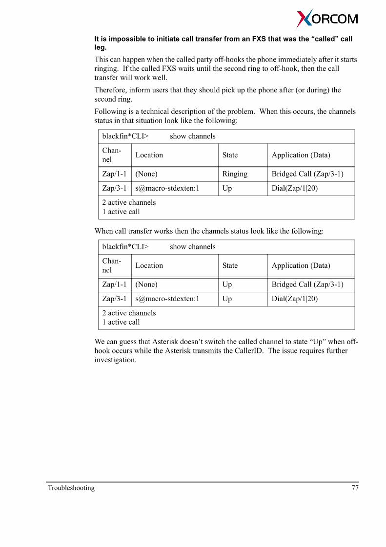
It is impossible to initiate call transfer from an FXS that was the “called” call leg. This can happen when the called party off-hooks the phone immediately after it starts ringing. If the called FXS waits until the second ring to off-hook, then the call transfer will work well. Therefore, inform users that they should pick up the phone after (or during) the second ring.Following is a technical description of the problem. When this occurs, the channels status in that situation look like the following:
blackfin*CLI> show channels
Chan-nel Location State Application (Data)
Zap/1-1 (None) Ringing Bridged Call (Zap/3-1)
Zap/3-1 s@macro-stdexten:1 Up Dial(Zap/1|20)
2 active channels 1 active call
When call transfer works then the channels status look like the following:
blackfin*CLI> show channels
Chan-nel Location State Application (Data)
Zap/1-1 (None) Up Bridged Call (Zap/3-1)
Zap/3-1 s@macro-stdexten:1 Up Dial(Zap/1|20)
2 active channels 1 active call
We can guess that Asterisk doesn’t switch the called channel to state “Up” when off-hook occurs while the Asterisk transmits the CallerID. The issue requires further investigation.
Troubleshooting 77

VoIP Related Issues
Symptom Asterisk rejects any attempt to call any service provider (Zaptel, VoIP) when the call is made from a CISCO SIP phone. At the same time it is possible to call an internal extension. SolutionManually add parameter insecure=port to the corresponding user section in file users.conf.Technical description The Asterisk returns SIP response 404 for any INVITE where R-URI’s user name is an external telephone number. The problem occurs because Asterisk tries to find a peer in its internal peer list by comparing both the IP address and the port where the INVITE came from. A peer is added to the list after successful registration. Please note that CISCO phones send REGISTER messages from port 5060 but INVITE messages from other ports. Therefore, the Asterisk can’t find the previously registered peer in the list. When parameter insecure=port is defined, then Asterisk doesn’t check the peer IP port and everything works well.
Symptom It is impossible to make calls when more than one SIP extension are located behind the same NAT router.Solution Manually add parameter insecure=port to the corresponding user section in file users.conf.
How do I configure the XR1000 to work with Internet and LAN SIP extensions when it is located behind a NAT router with a permanent external IP address.When the PBX is installed behind a NAT router with a permanent external IP address but should serve SIP endpoints that are located on the Internet, then it is necessary to configure your environment in the following way:1. Define your PBX as the DMZ host (in terms of D-Link routers) or alternatively,
make port forwarding for the following ports:• 5060/udp — needed for SIP signaling • 10000/udp-20000/udp — needed for voice packets transmit (RTP)
2. In the sip.conf file, in the general section, configure the following two PBX global SIP parameters:• externip = 62.xxx.xxx.xxx • localnet=192.168.0.0/255.255.0.0where,62.xxx.xxx.xxx = external IP address of the NAT router
78 XR1000
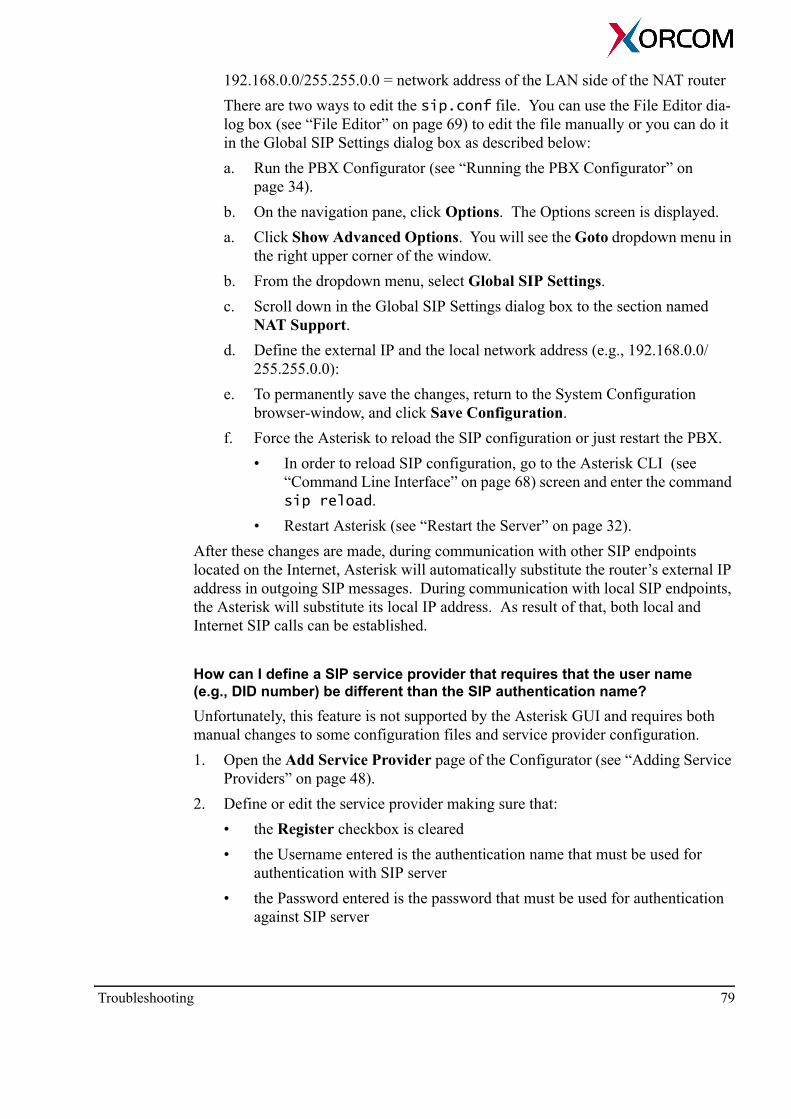
192.168.0.0/255.255.0.0 = network address of the LAN side of the NAT routerThere are two ways to edit the sip.conf file. You can use the File Editor dia-log box (see “File Editor” on page 69) to edit the file manually or you can do it in the Global SIP Settings dialog box as described below:a. Run the PBX Configurator (see “Running the PBX Configurator” on
page 34).b. On the navigation pane, click Options. The Options screen is displayed. a. Click Show Advanced Options. You will see the Goto dropdown menu in
the right upper corner of the window.b. From the dropdown menu, select Global SIP Settings.c. Scroll down in the Global SIP Settings dialog box to the section named
NAT Support. d. Define the external IP and the local network address (e.g., 192.168.0.0/
255.255.0.0):e. To permanently save the changes, return to the System Configuration
browser-window, and click Save Configuration.f. Force the Asterisk to reload the SIP configuration or just restart the PBX.
• In order to reload SIP configuration, go to the Asterisk CLI (see “Command Line Interface” on page 68) screen and enter the command sip reload.
• Restart Asterisk (see “Restart the Server” on page 32). After these changes are made, during communication with other SIP endpoints located on the Internet, Asterisk will automatically substitute the router’s external IP address in outgoing SIP messages. During communication with local SIP endpoints, the Asterisk will substitute its local IP address. As result of that, both local and Internet SIP calls can be established.
How can I define a SIP service provider that requires that the user name (e.g., DID number) be different than the SIP authentication name?Unfortunately, this feature is not supported by the Asterisk GUI and requires both manual changes to some configuration files and service provider configuration.1. Open the Add Service Provider page of the Configurator (see “Adding Service
Providers” on page 48).2. Define or edit the service provider making sure that:
• the Register checkbox is cleared• the Username entered is the authentication name that must be used for
authentication with SIP server• the Password entered is the password that must be used for authentication
against SIP server
Troubleshooting 79
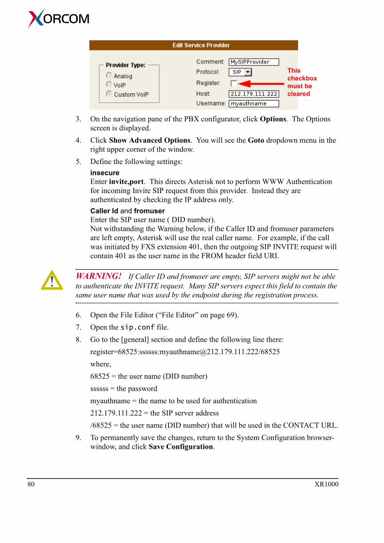
3. On the navigation pane of the PBX configurator, click Options. The Options screen is displayed.
4. Click Show Advanced Options. You will see the Goto dropdown menu in the right upper corner of the window.
5. Define the following settings: insecure Enter invite,port. This directs Asterisk not to perform WWW Authentication for incoming Invite SIP request from this provider. Instead they are authenticated by checking the IP address only.Caller Id and fromuser Enter the SIP user name ( DID number). Not withstanding the Warning below, if the Caller ID and fromuser parameters are left empty, Asterisk will use the real caller name. For example, if the call was initiated by FXS extension 401, then the outgoing SIP INVITE request will contain 401 as the user name in the FROM header field URI.
WARNING! If Caller ID and fromuser are empty, SIP servers might not be able to authenticate the INVITE request. Many SIP servers expect this field to contain the same user name that was used by the endpoint during the registration process.
6. Open the File Editor (“File Editor” on page 69). 7. Open the sip.conf file. 8. Go to the [general] section and define the following line there:
register=68525:ssssss:[email protected]/68525where,68525 = the user name (DID number)ssssss = the passwordmyauthname = the name to be used for authentication212.179.111.222 = the SIP server address/68525 = the user name (DID number) that will be used in the CONTACT URL.
9. To permanently save the changes, return to the System Configuration browser-window, and click Save Configuration.
This checkbox must be cleared
80 XR1000

Internet SIP extensions cannot register on the XR1000. The LAN sniffing shows that the REGISTER messages arrives to the XR1000 but they do not appear in the Asterisk SIP trace (“sip debug”).To solve this:1. Open the File Editor (“File Editor” on page 69). 2. Open the sip.conf file. 3. Define srvlookup=no.4. Restart Asterisk.
How can I make a LAN trace on the XR1000?You can do this using the tcpdump utility that is pre-installed on XR1000:1. Connect via SSH to theXR1000.2. Log-in using the User Name root. Use the same password that you use to con-
nect to the XR1000 browser-based configurator.3. Run tcpdump for the appropriate interface and capturing filter. For example, the
command below may be used for recording a SIP trace on the XR1000 WAN interface (eth0) and saving it in file /tmp/trc.cap: tcpdump -i eth0 -s 0 -w /tmp/trc.cap 'port 5060'
4. Press Ctrl-C in order to stop the tcpdump.
Note: The folder /tmp is mounted on the RAM drive. Therefore, you should be careful of the trace file size.
5. Copy the file to your computer using any SCP file transfer utility.6. Review the trace by using the Wireshark (http://www.wireshark.org) analyzer.
I have two accounts at the same SIP provider. How can I handle incoming calls from those accounts? It seems like Asterisk doesn't distinguish between them and routes incoming calls to incorrect destinations.To solve this, you can create a new context—for example: from-providers—and define the required call routing based on the called number. The new context must be included into the default context. For example:
[default]include => featuresinclude => from-providersexten => *98,1,VoiceMailMain ...................[from-providers]exten = 55791883,1,Goto(default|200|1)exten = 31015977,1,Goto(default|200|1).................
Troubleshooting 81

PBX Configuration InternalsSometimes you need to make changes in the XR1000 dialing plan by manually editing the Asterisk configuration files. This topic explains how the PBX GUI con-figurator builds objects in the users.conf and extensions.conf files. All of the PBX extensions and service providers are configured in the users.conf file. In the example below you can see a definition of extension 401 and two service providers. In the example they are placed side-by-side whereas in the users.conf file the second follows the first:
[401]callwaiting = yescontext = numberplan-custom-1fullname = FXS 1cid_number = 401hasagent = nohasdirectory = nohasiax = nohasmanager = nohassip = nohasvoicemail = yeshost = dynamicmailbox = 401threewaycalling = yesvmsecret = 1234secret = 1234signalling = fxo_lszapchan = 1registeriax = noregistersip = nocanreinvite = nonat = nodtmfmode = rfc2833disallow = allallow = all
[402].............
[trunk_1]disallow=allallow = allcontext = DID_trunk_1dialformat = ${EXTEN:1}hasexten = nohasiax = nohassip = yeshost = 1.2.3.4port = 5060registeriax = noregistersip = yessecret = mypasswordtrunkname = Custom - MySIP-Providertrunkstyle = customvoipusername = myusername
[trunk_2]callerid = asreceivedcontext = DID_trunk_2group = 2hasexten = nohasiax = nohassip = notrunkname = Ports 13,14trunkstyle = analogzapchan = 13,14
82 XR1000

The provider [trunk_1] is a custom VoIP provider that was defined in the GUI as fol-lows:
The provider [trunk_2] is a provider that represents analog (FXO) lines. It was defined as follows:
Two global variables will be created in the extensions.conf file—trunk_1 and trunk_2—and two contexts:
[global]
trunk_1 = SIP/trunk_1
trunk_2 = Zap/g2
.......
[DID_trunk_1]
include = default
[DID_trunk_2]
include = default
PBX Configuration Internals 83

If you create calling rules for outbound calls via those providers, like the rules in the following picture, then Asterisk creates corresponding rules in the [numberplan-custom-1] context as illustrated below the picture:
[numberplan-custom-1]
plancomment = DialPlan1
include = default
include = parkedcalls
exten = _8X.,1,Macro(trunkdial,${trunk_1}/${EXTEN:1})
comment = _8X.,1,CallingToMySIPProvider,custom
exten = _9X.,1,Macro(trunkdial,${trunk_2}/${EXTEN:1})
comment = _9X.,1,CallingViaFXOLines,custom
If you create calling rules for incoming calls, like the rules in the following picture, then the contexts DID_trunk_1 and DID_trunk_2 will be populated as illustrated below the picture:
[DID_trunk_1]
include = default
exten = _X.,1,Goto(default|401|1)
exten = s,1,Goto(default|401|1)
[DID_trunk_2]
include = default
exten = _X.,1,Goto(default|402|1)
exten = s,1,Goto(default|402|1)
84 XR1000
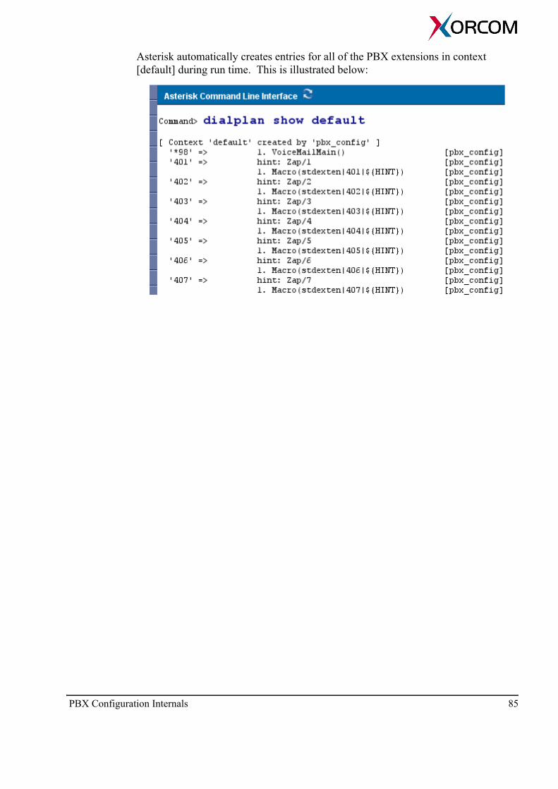
Asterisk automatically creates entries for all of the PBX extensions in context [default] during run time. This is illustrated below:
PBX Configuration Internals 85

XR1000 Configuration TipsXR1000 runs Asterisk Open Source PBX software which is extremely flexible. However, not all the customization possibilities are available via the browser-based configurator. This section contains information that will help you implement or cus-tomize functions by tweaking the Asterisk configuration files.
Recommended Process: Tweaking the Dialing Plan
When tweaking the dialing plan, we recommend following these steps:1. Backup the current configuration (see “Backup and Restore” on page 27).2. Make changes in the Asterisk configuration files. To access the Asterisk con-
figuration files either:Use the File Editor See “File Editor” on page 69Use an SSH TerminalConnect to the XR1000 using an SSH terminal client. Then, use Linux vi editor for changing configuration files that are located at folder /etc/asterisk.
3. Click Activate Changes to apply the changes (see the explanation on p. 35).4. Test the system.5. Click Save Configuration to save the changes on the flash disk (see the
warning on p. 8). 6. Backup the new configuration.
Deleting all Content of a Specific Voicemail Box
Before a user can delete the content of a specific voicemail box, the appropriate files are tweaked. After they are tweaked, deleting is a two step process.
After Tweaking 1. Dial *97. Asterisk authenticates the user by password. Following password
authentication, Asterisk asks for the voicemail box number to be cleaned up.2. Dial the number of the voicemail box. Asterisk plays back the voicemail box
number and ask for confirmation. Following confirmation, Asterisk deletes all the voice messages.
Note: You can define a phone number other than *97 and change the authentication password 1234 (see command Authenticate below).
86 XR1000

Tweaking that Enables Deleting Voicemail Box Content1. Create context [vmbox-cleanup] in the file extensions.conf:
[vmbox-cleanup]
exten=*97,1,Answer
exten=*97,n,Authenticate(1234|j) ; <Change the password here>
exten=*97,n,Playback(vm-login)
exten=*97,n,Read(mbox||3|||10)
exten=*97,n,Playback(record/mailbox)
exten=*97,n,SayDigits(${mbox})
exten=*97,n,Playback(record/willBeCleanedUp)
exten=*97,n,Read(answer||1|||10)
exten=*97,n,Gotoif($["${answer}" = "1"]?delete:cancel)
exten=*97,n(delete),System(rm -rf /mnt/vm/default/"${mbox}")
exten=*97,n,Playback(record/mailboxCleanedUp)
exten=*97,n,Hangup
exten=*97,n(cancel),Playback(record/canceled)
exten=*97,n,Hangup
exten=*97,n+101,Hangup
2. Add the context vmbox-cleanup to the corresponding dial plan context. For example, by default AsteriskGUI creates DialPlan1 and the corresponding con-text is numberplan-custom-1. Adding the new context looks like this:
[numberplan-custom-1]
include = vmbox-cleanup
.....
3. On the Record Menu screen (see “Record a Menu” on page 66), record the fol-lowing files:
File name Suggested Text
mailbox “Mailbox?”
willBeCleanedUp "will be cleaned up. Press 1 for confirmation or 2 for cancel."
mailboxCleanedUp "the mailbox has be cleaned up"
canceled “canceled.”
XR1000 Configuration Tips 87

Defining a Voicemail Box Number Different than the Extension Number
This is necessary if, for example, voice mail messages for extensions 401, 402 and 403 must be forwarded to voice mail box 401. The other extensions must not be affected.1. Create context [define-vmbox] in file extensions.conf:
[define-vmbox]
exten => s,1,Set(VMbox=${ARG1})
exten => s,n,Set(VMbox=${IF($["${ARG1}"="402"]?"401":${VMbox})})
exten => s,n,Set(VMbox=${IF($["${ARG1}"="403"]?"401":${VMbox})})
exten => s,n,Return
2. In the existing context [macro-stdexten] in file extensions.conf, replace argument ${ARG1} with ${VMbox} in all calls to the Voicemail() func-tion and add call to define-vmbox subroutine at the beginning. Finally you should get the following (the changes are presented as bold text):[macro-stdexten];
exten => s,1,Gosub(define-vmbox,s,1)
exten => s,2,Dial(${ARG2},20)
exten => s,3,Goto(s-${DIALSTATUS},1)
exten => s-NOANSWER,1,Voicemail(${VMbox},u)
exten => s-NOANSWER,2,Hangup
exten => s-BUSY,1,Voicemail(${VMbox},b)
exten => s-BUSY,2,Hangup
exten => _s-.,1,Goto(s-NOANSWER,1)
exten => a,1,VoicemailMain(${VMbox})
Defining Shortcut Numbers
Many users want to use three or four digits numbers for dialing frequently used phone numbers. These numbers are called “shortcut numbers” or simply “shortcuts”.In this example, there are two defined Service Providers:
• Ports 13,14 This includes the two FXO lines used for domestic calls.
• MySIPProvider This provider is used for VoIP calls to the United Kingdom.
We need to define the following shortcuts:
Shortcut number Full number Service Provider
501 (to call Alice) 07712345678 “Ports 13,14” (the FXO ports)
502 (to call Bob) 07787654321 “Ports 13,14” (the FXO ports)
503 (to call my busi-ness partner in London) 442081234567 “MySIPProvider”
88 XR1000
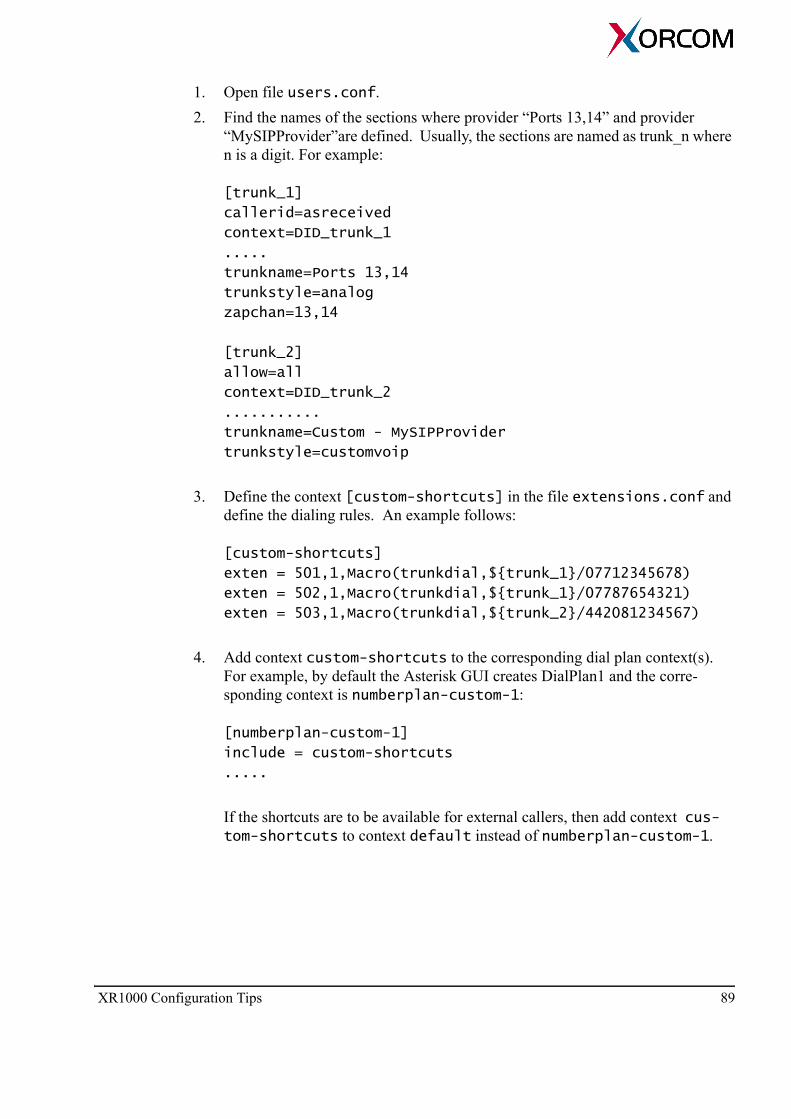
1. Open file users.conf.2. Find the names of the sections where provider “Ports 13,14” and provider
“MySIPProvider”are defined. Usually, the sections are named as trunk_n where n is a digit. For example:
[trunk_1]
callerid=asreceived
context=DID_trunk_1
.....
trunkname=Ports 13,14
trunkstyle=analog
zapchan=13,14
[trunk_2]
allow=all
context=DID_trunk_2
...........
trunkname=Custom - MySIPProvider
trunkstyle=customvoip
3. Define the context [custom-shortcuts] in the file extensions.conf and define the dialing rules. An example follows:
[custom-shortcuts]
exten = 501,1,Macro(trunkdial,${trunk_1}/07712345678)
exten = 502,1,Macro(trunkdial,${trunk_1}/07787654321)
exten = 503,1,Macro(trunkdial,${trunk_2}/442081234567)
4. Add context custom-shortcuts to the corresponding dial plan context(s). For example, by default the Asterisk GUI creates DialPlan1 and the corre-sponding context is numberplan-custom-1:
[numberplan-custom-1]
include = custom-shortcuts
.....
If the shortcuts are to be available for external callers, then add context cus-tom-shortcuts to context default instead of numberplan-custom-1.
XR1000 Configuration Tips 89

Cables Pin Out
RJ-45 Pin Auxiliary Output Port Auxiliary Input Port
1 Relay 1 Common Input 1
2 Relay 1 Normally Open Ground
3 Relay 1 Normally Closed Input 3
4 Not Connected Ground
5 Not Connected Input 2
6 Relay 2 Common Ground
7 Relay 2 Normally Open Input 4
8 Relay 2 Normally Closed Ground
RJ-11 Pin Function RJ-11 Pin Function
1 Not Connected 4 Tip
2 Not Connected 5 Not Connected
3 Ring 6 Not Connected
RJ-11 6 Position Plug RJ-11 6 Position Port
RJ-45 8 PositionModular Plug
RJ-45 8 PositionModular Port
90 XR1000