xilinx isim hardware co-simulation tutorial: interacting ... · isim hardware co-simulation...
TRANSCRIPT
ISim Hardware Co-SimulationTutorial:Interacting with Spartan-6Memory Controller andOn-Board DDR2 Memory
UG818 (v 13.2) July 28, 2011
Xilinx is disclosing this user guide, manual, release note, and/or specification (the “Documentation”) to yousolely for use in the development of designs to operate with Xilinx hardware devices. You may not reproduce,distribute, republish, download, display, post, or transmit the Documentation in any form or by any meansincluding, but not limited to, electronic, mechanical, photocopying, recording, or otherwise, without the priorwritten consent of Xilinx. Xilinx expressly disclaims any liability arising out of your use of the Documentation.Xilinx reserves the right, at its sole discretion, to change the Documentation without notice at any time. Xilinxassumes no obligation to correct any errors contained in the Documentation, or to advise you of any correctionsor updates. Xilinx expressly disclaims any liability in connection with technical support or assistance that may beprovided to you in connection with the Information.
THE DOCUMENTATION IS DISCLOSED TO YOU “AS-IS” WITH NOWARRANTY OF ANY KIND. XILINXMAKES NO OTHER WARRANTIES, WHETHER EXPRESS, IMPLIED, OR STATUTORY, REGARDINGTHE DOCUMENTATION, INCLUDING ANY WARRANTIES OF MERCHANTABILITY, FITNESS FOR APARTICULAR PURPOSE, OR NONINFRINGEMENT OF THIRD-PARTY RIGHTS. IN NO EVENT WILLXILINX BE LIABLE FOR ANY CONSEQUENTIAL, INDIRECT, EXEMPLARY, SPECIAL, OR INCIDENTALDAMAGES, INCLUDING ANY LOSS OF DATA OR LOST PROFITS, ARISING FROM YOUR USE OF THEDOCUMENTATION.
© Copyright 2002-2011 Xilinx Inc. All Rights Reserved. XILINX, the Xilinx logo, the Brand Window and otherdesignated brands included herein are trademarks of Xilinx, Inc. All other trademarks are the property of theirrespective owners. The PowerPC name and logo are registered trademarks of IBM Corp., and used under license.All other trademarks are the property of their respective owners.
Tutorial: Interacting with the Spartan-6 Memory Controller and On-Board DDR2 Memory2 www.xilinx.com UG818 (v 13.2) July 28, 2011
Table of ContentsChapter 1 Introduction ............................................................................................... 5
Prerequisites......................................................................................................... 6Tutorial Files......................................................................................................... 6
Chapter 2 Tutorial ....................................................................................................... 9
Step 1: Generating a Design Using the MIG Tool ............................................. 9Step 2: Creating a Test Bench .............................................................................. 15Step 3: Creating a Custom Constraints File........................................................ 16Step 4: Compiling the Design for Hardware Co-Simulation ............................ 19Step 5: Running ISim Hardware Co-Simulation ............................................... 22
Appendix Additional Resources ...............................................................................27
Tutorial: Interacting with the Spartan-6 Memory Controller and On-Board DDR2 MemoryUG818 (v 13.2) July 28, 2011 www.xilinx.com 3

Tutorial: Interacting with the Spartan-6 Memory Controller and On-Board DDR2 Memory4 www.xilinx.com UG818 (v 13.2) July 28, 2011

Chapter 1
IntroductionThis tutorial describes how to use ISim hardware co-simulation to interact with theSpartan®-6 FPGA memory controller block (MCB) and drive external DDR2 memoryfrom your HDL test bench at run time.
External memory is commonly used in embedded, image, and video processingapplications that require a large amount of memory.
When developing an FPGA design that uses external memory, it is often challengingto verify the whole design including the memory controller and external memorymodule. Traditionally, we either simulate the whole design in software, or run the wholedesign in hardware. A full software simulation approach is useful in two aspects. Itoffers full visibility into the design and allows the test bench or design to be changedand re-verified in a rapid manner. The challenges, however, are getting an accuratesimulation model of the external memory module and achieving a reasonable simulationspeed. In contrast, running the design in hardware addresses these problems, but at thecost of reduced visibility into the design. It is also very complex to set up and change thetest bench in hardware.
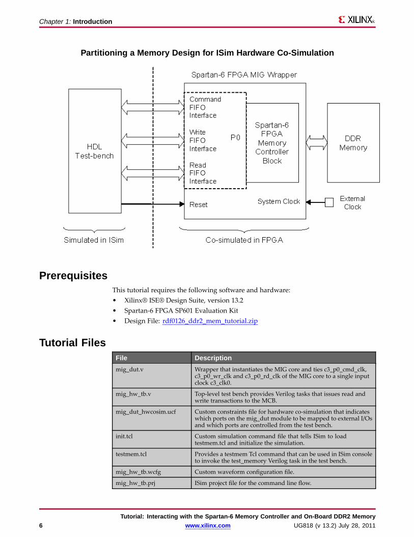
ISim hardware co-simulation is a third option in your toolbox. It gives you the flexibilityto run a portion of your design in hardware while simulating the rest in software. Thememory controller and external memory are, for example, good candidates to put inhardware so that they are modeled accurately and simulated quickly. The test bench andthe application logic in your design, which are under development, should be simulatedin software so you can change, verify and debug them easily and rapidly. The followingfigure shows how a design that uses a memory controller and external memory, can bepartitioned to leverage the ISim hardware co-simulation features.
Tutorial: Interacting with the Spartan-6 Memory Controller and On-Board DDR2 MemoryUG818 (v 13.2) July 28, 2011 www.xilinx.com 5
Chapter 1: Introduction
Partitioning a Memory Design for ISim Hardware Co-Simulation
PrerequisitesThis tutorial requires the following software and hardware:• Xilinx® ISE® Design Suite, version 13.2• Spartan-6 FPGA SP601 Evaluation Kit• Design File: rdf0126_ddr2_mem_tutorial.zip
Tutorial FilesFile Descriptionmig_dut.v Wrapper that instantiates the MIG core and ties c3_p0_cmd_clk,
c3_p0_wr_clk and c3_p0_rd_clk of the MIG core to a single inputclock c3_clk0.
mig_hw_tb.v Top-level test bench provides Verilog tasks that issues read andwrite transactions to the MCB.
mig_dut_hwcosim.ucf Custom constraints file for hardware co-simulation that indicateswhich ports on the mig_dut module to be mapped to external I/Osand which ports are controlled from the test bench.
init.tcl Custom simulation command file that tells ISim to loadtestmem.tcl and initialize the simulation.
testmem.tcl Provides a testmem Tcl command that can be used in ISim consoleto invoke the test_memory Verilog task in the test bench.
mig_hw_tb.wcfg Custom waveform configuration file.
mig_hw_tb.prj ISim project file for the command line flow.
Tutorial: Interacting with the Spartan-6 Memory Controller and On-Board DDR2 Memory6 www.xilinx.com UG818 (v 13.2) July 28, 2011
Chapter 1: Introduction
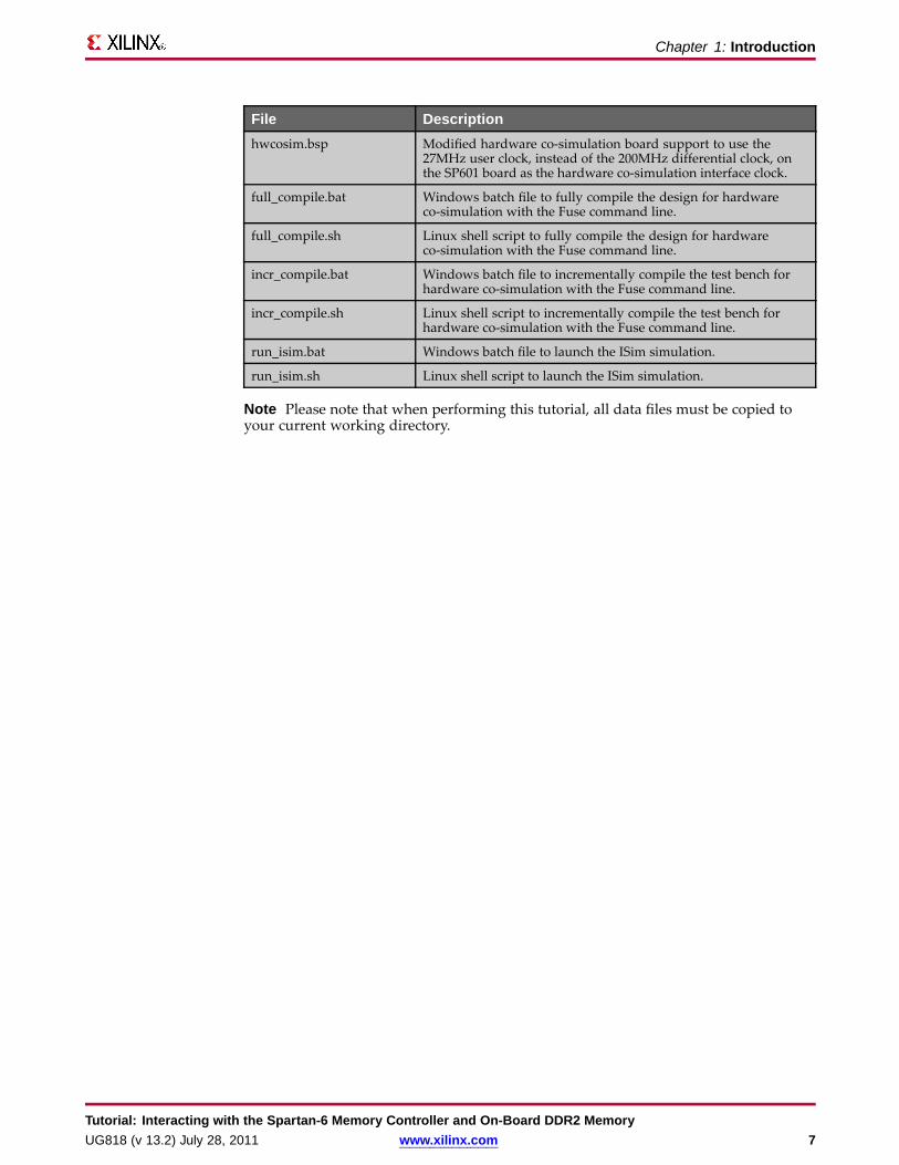
File Descriptionhwcosim.bsp Modified hardware co-simulation board support to use the
27MHz user clock, instead of the 200MHz differential clock, onthe SP601 board as the hardware co-simulation interface clock.
full_compile.bat Windows batch file to fully compile the design for hardwareco-simulation with the Fuse command line.
full_compile.sh Linux shell script to fully compile the design for hardwareco-simulation with the Fuse command line.
incr_compile.bat Windows batch file to incrementally compile the test bench forhardware co-simulation with the Fuse command line.
incr_compile.sh Linux shell script to incrementally compile the test bench forhardware co-simulation with the Fuse command line.
run_isim.bat Windows batch file to launch the ISim simulation.
run_isim.sh Linux shell script to launch the ISim simulation.
Note Please note that when performing this tutorial, all data files must be copied toyour current working directory.
Tutorial: Interacting with the Spartan-6 Memory Controller and On-Board DDR2 MemoryUG818 (v 13.2) July 28, 2011 www.xilinx.com 7

Tutorial: Interacting with the Spartan-6 Memory Controller and On-Board DDR2 Memory8 www.xilinx.com UG818 (v 13.2) July 28, 2011
Chapter 2
TutorialThe following section describes the five steps for running a memory design throughISim hardware co-simulation.1. Generate a Spartan®-6 memory reference design using the Memory Interface
Generator (MIG) tool in CORE Generator™.2. Create a test bench to exercise the memory reference design.3. Create a custom constraints file to specify which ports on the design are controlled
by ISim and which are mapped to external I/Os.4. Compile the test bench for ISim simulation with the design targeted for hardware
co-simulation.5. Connect the target FPGA board to your computer and run the ISim simulation.
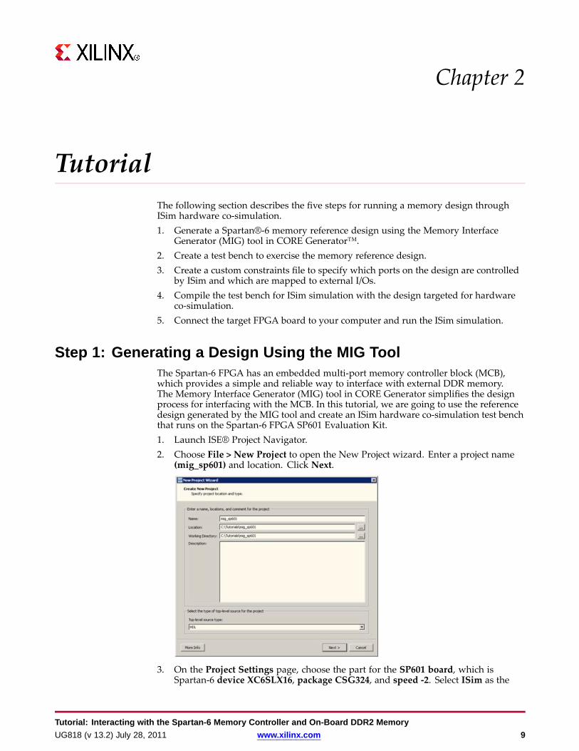
Step 1: Generating a Design Using the MIG ToolThe Spartan-6 FPGA has an embedded multi-port memory controller block (MCB),which provides a simple and reliable way to interface with external DDR memory.The Memory Interface Generator (MIG) tool in CORE Generator simplifies the designprocess for interfacing with the MCB. In this tutorial, we are going to use the referencedesign generated by the MIG tool and create an ISim hardware co-simulation test benchthat runs on the Spartan-6 FPGA SP601 Evaluation Kit.1. Launch ISE® Project Navigator.2. Choose File > New Project to open the New Project wizard. Enter a project name
(mig_sp601) and location. Click Next.
3. On the Project Settings page, choose the part for the SP601 board, which isSpartan-6 device XC6SLX16, package CSG324, and speed -2. Select ISim as the
Tutorial: Interacting with the Spartan-6 Memory Controller and On-Board DDR2 MemoryUG818 (v 13.2) July 28, 2011 www.xilinx.com 9

Chapter 2: Tutorial
Simulator and Verilog as the Preferred Language. Click Next and then Finish tocomplete the project creation.
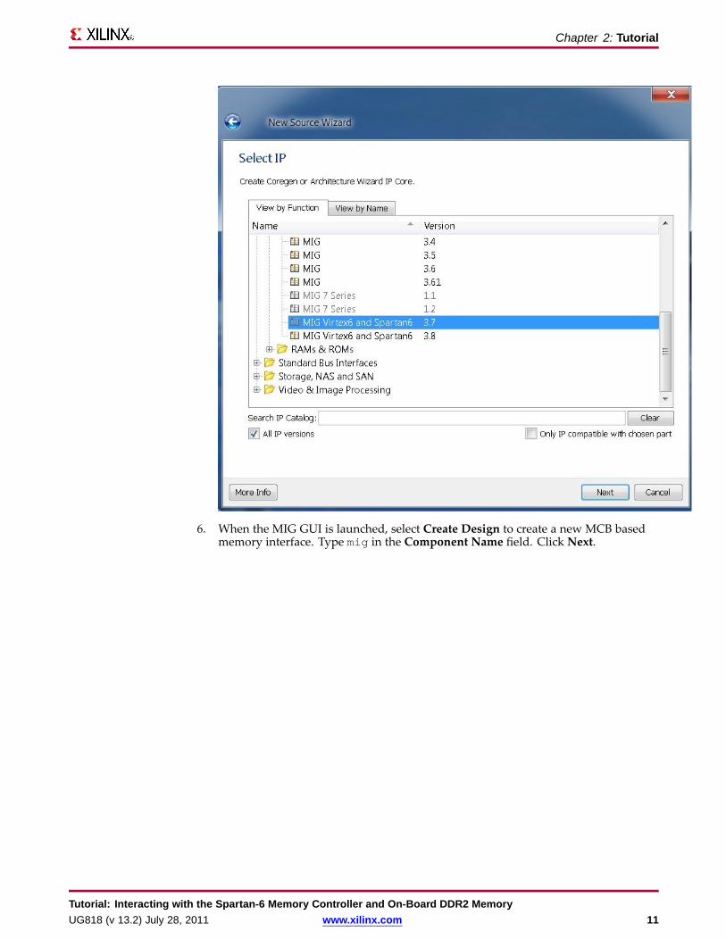
4. Choose Project > New Source to open the New Source Wizard. Select IP (COREGenerator & Architecture Wizard) and name the IP mig. Click Next.
5. SelectMIG version 3.7 from the IP list. Click Next and then Finish.
Tutorial: Interacting with the Spartan-6 Memory Controller and On-Board DDR2 Memory10 www.xilinx.com UG818 (v 13.2) July 28, 2011
Chapter 2: Tutorial
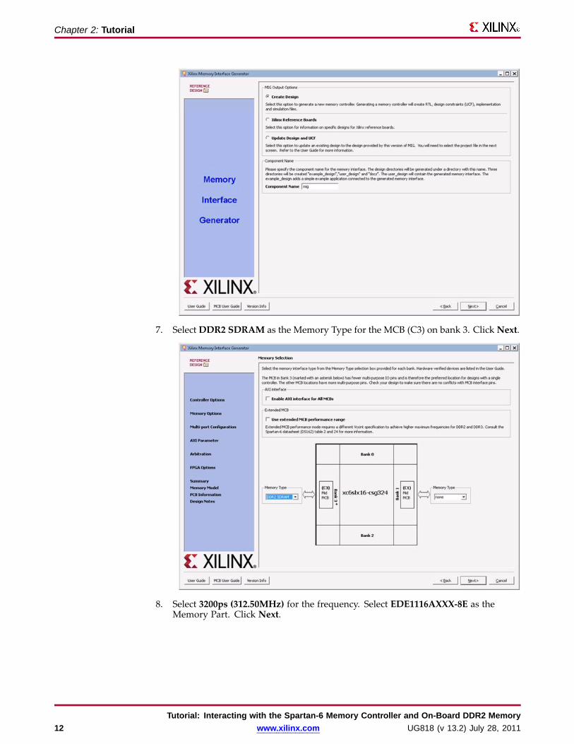
6. When the MIG GUI is launched, select Create Design to create a new MCB basedmemory interface. Type mig in the Component Name field. Click Next.
Tutorial: Interacting with the Spartan-6 Memory Controller and On-Board DDR2 MemoryUG818 (v 13.2) July 28, 2011 www.xilinx.com 11
Chapter 2: Tutorial
7. Select DDR2 SDRAM as the Memory Type for the MCB (C3) on bank 3. Click Next.
8. Select 3200ps (312.50MHz) for the frequency. Select EDE1116AXXX-8E as theMemory Part. Click Next.
Tutorial: Interacting with the Spartan-6 Memory Controller and On-Board DDR2 Memory12 www.xilinx.com UG818 (v 13.2) July 28, 2011

Chapter 2: Tutorial
9. Use the default settings on the Memory Options page. Click Next.
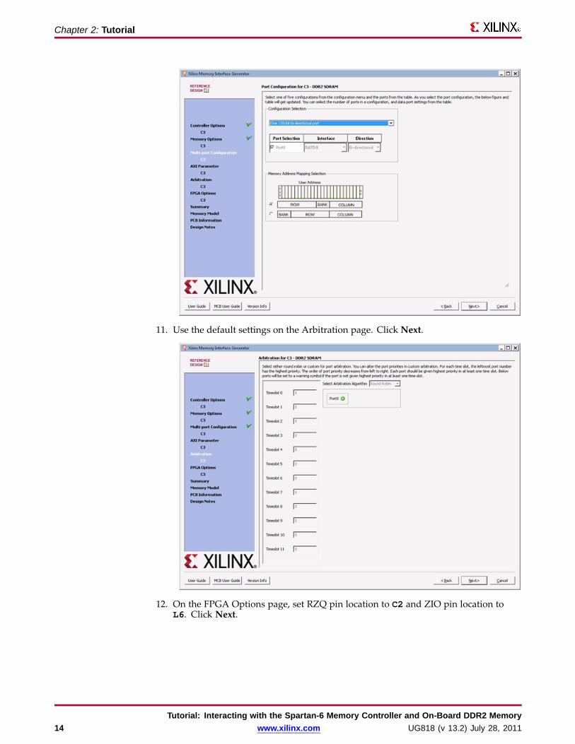
10. Select One 128-bit bi-directional port as the Port Configuration. Click Next.
Tutorial: Interacting with the Spartan-6 Memory Controller and On-Board DDR2 MemoryUG818 (v 13.2) July 28, 2011 www.xilinx.com 13
Chapter 2: Tutorial
11. Use the default settings on the Arbitration page. Click Next.
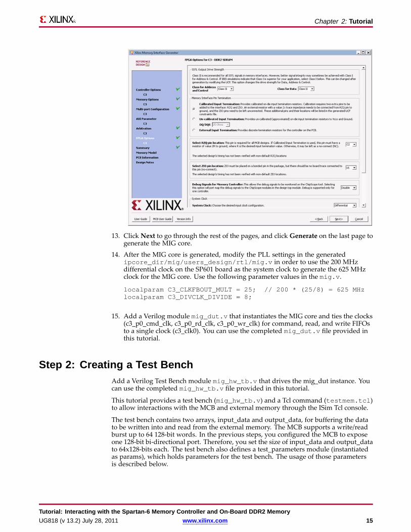
12. On the FPGA Options page, set RZQ pin location to C2 and ZIO pin location toL6. Click Next.
Tutorial: Interacting with the Spartan-6 Memory Controller and On-Board DDR2 Memory14 www.xilinx.com UG818 (v 13.2) July 28, 2011
Chapter 2: Tutorial
13. ClickNext to go through the rest of the pages, and clickGenerate on the last page togenerate the MIG core.
14. After the MIG core is generated, modify the PLL settings in the generatedipcore_dir/mig/users_design/rtl/mig.v in order to use the 200 MHzdifferential clock on the SP601 board as the system clock to generate the 625 MHzclock for the MIG core. Use the following parameter values in the mig.v.
localparam C3_CLKFBOUT_MULT = 25; // 200 * (25/8) = 625 MHzlocalparam C3_DIVCLK_DIVIDE = 8;
15. Add a Verilog modulemig_dut.v that instantiates the MIG core and ties the clocks(c3_p0_cmd_clk, c3_p0_rd_clk, c3_p0_wr_clk) for command, read, and write FIFOsto a single clock (c3_clk0). You can use the completed mig_dut.v file provided inthis tutorial.
Step 2: Creating a Test BenchAdd a Verilog Test Bench module mig_hw_tb.v that drives the mig_dut instance. Youcan use the completed mig_hw_tb.v file provided in this tutorial.
This tutorial provides a test bench (mig_hw_tb.v) and a Tcl command (testmem.tcl)to allow interactions with the MCB and external memory through the ISim Tcl console.
The test bench contains two arrays, input_data and output_data, for buffering the datato be written into and read from the external memory. The MCB supports a write/readburst up to 64 128-bit words. In the previous steps, you configured the MCB to exposeone 128-bit bi-directional port. Therefore, you set the size of input_data and output_datato 64x128-bits each. The test bench also defines a test_parameters module (instantiatedas params), which holds parameters for the test bench. The usage of those parametersis described below.
Tutorial: Interacting with the Spartan-6 Memory Controller and On-Board DDR2 MemoryUG818 (v 13.2) July 28, 2011 www.xilinx.com 15
Chapter 2: Tutorial
The following Verilog tasks are defined in the test bench:
• clear_input_output_data - Fills the input_data and output_data array withzeros.
• compare_input_output_data(input nwords) - Compares nwords words ofdata in the input_data and output_data array, and reports any mismatchesfound.
• use_walking_pattern(input b) Fills the input_data array with walkingzeros pattern if b = 0 or with walking ones pattern if b = 1.
• write_data(input start_addr, input burst_size) - Writesburst_size words of data from the input_data array to the external memorystarting at address start_addr. It first pushes data to the write FIFO interface(c3_p0_wr_*) on the MCB and then pushes a write command to the commandFIFO interface (c3_p0_cmd_*).
• read_data(input start_addr, input burst_size) - Reads burst_sizewords of data from the external memory starting at address start_addr intothe output_data array. It first pushes a read command to the command FIFOinterface (c3_p0_cmd_*) on the PCB and then pulls data from the read FIFOinterface (c3_p0_rd_*).
• test_memory - Writes data from the input_data array into the external memoryof a specified region and then read the data back from the same region to theoutput_data array. The memory region is specified by params.StartAddressand params.EndAddress. The data pattern used to fill the input_data array isspecified by params.DataPattern (0 – use the current data in input_data, 1 – usewalking zeros, 2 – use walking ones).
The testmem Tcl command sets the value of StartAddress, EndAddress, andDataPattern in the params module. It then toggles the run_test_triggersignal in the test bench. Upon a rising edge of the run_test_trigger signal, thetest_read_write task is called to exercise the write and read transaction on theexternal memory and check to make sure the data are written correctly to the externalmemory by comparing against the readback data.
Step 3: Creating a Custom Constraints FilePartitioning the Design into Lock-step and Free-running Portion
The key concept of this tutorial is to partition the design into two portions:
• A free-running portion that interfaces with the external memory through theSpartan-6 MCB. It connects to external I/Os and clocks, and runs at full memoryclock speed.
• A lock-step portion that is driven by the HDL test bench through ISim. It issynchronized to the ISim simulation, and receives stimuli and clock events virtuallyover the hardware co-simulation interface. As a result, it runs at a much lower speed.
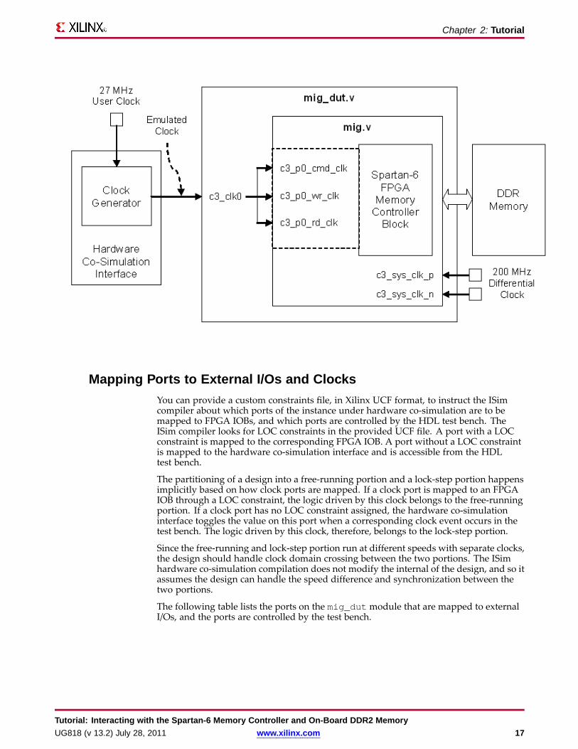
The following figure shows how the MIG design is clocked under hardwareco-simulation. The hardware co-simulation interface is inserted automatically duringthe compilation. It generates an emulated clock based on the 27 MHz user clock on theSP601 board. The emulated clock corresponds to the clock event on the c3_clk0 signal inthe test bench and drives the c3_clk0 port of mig_dut running in hardware. The systemclock for the MIG core is derived from the 200 MHz differential clock on the SP601 board.
Tutorial: Interacting with the Spartan-6 Memory Controller and On-Board DDR2 Memory16 www.xilinx.com UG818 (v 13.2) July 28, 2011
Chapter 2: Tutorial
Mapping Ports to External I/Os and ClocksYou can provide a custom constraints file, in Xilinx UCF format, to instruct the ISimcompiler about which ports of the instance under hardware co-simulation are to bemapped to FPGA IOBs, and which ports are controlled by the HDL test bench. TheISim compiler looks for LOC constraints in the provided UCF file. A port with a LOCconstraint is mapped to the corresponding FPGA IOB. A port without a LOC constraintis mapped to the hardware co-simulation interface and is accessible from the HDLtest bench.
The partitioning of a design into a free-running portion and a lock-step portion happensimplicitly based on how clock ports are mapped. If a clock port is mapped to an FPGAIOB through a LOC constraint, the logic driven by this clock belongs to the free-runningportion. If a clock port has no LOC constraint assigned, the hardware co-simulationinterface toggles the value on this port when a corresponding clock event occurs in thetest bench. The logic driven by this clock, therefore, belongs to the lock-step portion.
Since the free-running and lock-step portion run at different speeds with separate clocks,the design should handle clock domain crossing between the two portions. The ISimhardware co-simulation compilation does not modify the internal of the design, and so itassumes the design can handle the speed difference and synchronization between thetwo portions.
The following table lists the ports on the mig_dut module that are mapped to externalI/Os, and the ports are controlled by the test bench.
Tutorial: Interacting with the Spartan-6 Memory Controller and On-Board DDR2 MemoryUG818 (v 13.2) July 28, 2011 www.xilinx.com 17

Chapter 2: Tutorial
Partitioning ports on the mig_dut modulePorts mapped to external I/Os Ports controlled by the test bench
c3_sys_clk_pc3_sys_clk_nmcb3_dram_dqmcb3_dram_amcb3_dram_bamcb3_dram_ras_nmcb3_dram_cas_nmcb3_dram_we_nmcb3_dram_odtmcb3_dram_ckemcb3_dram_ckmcb3_dram_ck_nmcb3_dram_dqsmcb3_dram_dqs_nmcb3_dram_udqsmcb3_dram_udqs_nmcb3_dram_udmmcb3_dram_dmrzq3 zio3
c3_sys_rst_nc3_clk0c3_rst0c3_calib_donec3_p0_cmd_enc3_p0_cmd_instrc3_p0_cmd_blc3_p0_cmd_byte_addrc3_p0_cmd_emptyc3_p0_cmd_fullc3_p0_wr_enc3_p0_wr_maskc3_p0_wr_datac3_p0_wr_fullc3_p0_wr_emptyc3_p0_wr_countc3_p0_wr_underrunc3_p0_wr_errorc3_p0_rd_enc3_p0_rd_datac3_p0_rd_fullc3_p0_rd_emptyc3_p0_rd_countc3_p0_rd_overflowc3_p0_rd_error
The MIG tool creates an example UCF file. The following procedure describes using theUCF file as a template to create the custom constraints file for hardware co-simulation.1. Copy ipcore_dir/mig/user_design/par/mig.ucf to the ISim
project directory where mig_dut.v is located. Name the copied file asmig_dut_hwcosim.ucf.
2. Modify the mig_dut_hwcosim.ucf file as follows for the SP601 board. Changethe period constraint of TS_SYS_CLK3 to 5 ns as we use the 200 MHz differentialclock input on the SP601 as the system clock.
TIMESPEC "TS_SYS_CLK3" = PERIOD "SYS_CLK3" 5 ns HIGH 50 %;
Change the LOCconstraint for c3_sys_clk_n to K16, and c3_sys_clk_p to K15to match the pin assignments on SP601.
NET "c3_sys_clk_n" LOC = "K16";NET "c3_sys_clk_p" LOC = "K15";
3. Modify the mig_dut_hwcosim.ucf file for ISim hardware co-simulationrequirements.Add a wildcard character * at the beginning of the hierarchical path for the followingconstraints. This is required because the mig_dut will be wrapped as a submodulewhen it is compiled for hardware co-simulation.
NET "*memc?_wrapper_inst/mcb_ui_top_inst/mcb_raw_wrapper_inst/selfrefresh_mcb_mode" TIG;NET "*c?_pll_lock" TIG;NET "*memc?_wrapper_inst/mcb_ui_top_inst/mcb_raw_wrapper_inst/gen_term_calib.mcb_soft_calibration_top_inst/
mcb_soft_calibration_inst/CKE_Train" TIG; ##This path exists for DDR2NET "*memc3_infrastructure_inst/sys_clk_ibufg" TNM_NET = "SYS_CLK3";
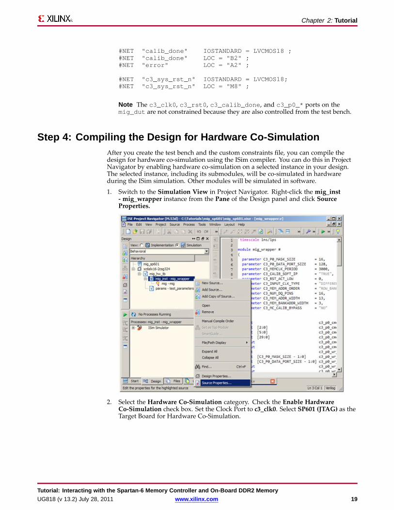
Comment out the constraints for error, calib_done, and c3_sys_rst_n,especially the LOCconstraints, as it will be controlled from the test bench.
#NET "error" IOSTANDARD = LVCMOS18 ;
Tutorial: Interacting with the Spartan-6 Memory Controller and On-Board DDR2 Memory18 www.xilinx.com UG818 (v 13.2) July 28, 2011
Chapter 2: Tutorial
#NET "calib_done" IOSTANDARD = LVCMOS18 ;#NET "calib_done" LOC = "B2" ;#NET "error" LOC = "A2" ;
#NET "c3_sys_rst_n" IOSTANDARD = LVCMOS18;#NET "c3_sys_rst_n" LOC = "M8" ;
Note The c3_clk0, c3_rst0, c3_calib_done, and c3_p0_* ports on themig_dut are not constrained because they are also controlled from the test bench.
Step 4: Compiling the Design for Hardware Co-SimulationAfter you create the test bench and the custom constraints file, you can compile thedesign for hardware co-simulation using the ISim compiler. You can do this in ProjectNavigator by enabling hardware co-simulation on a selected instance in your design.The selected instance, including its submodules, will be co-simulated in hardwareduring the ISim simulation. Other modules will be simulated in software.
1. Switch to the Simulation View in Project Navigator. Right-click the mig_inst- mig_wrapper instance from the Pane of the Design panel and click SourceProperties.
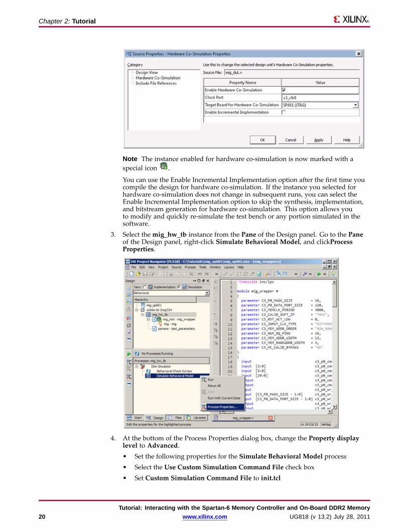
2. Select the Hardware Co-Simulation category. Check the Enable HardwareCo-Simulation check box. Set the Clock Port to c3_clk0. Select SP601 (JTAG) as theTarget Board for Hardware Co-Simulation.
Tutorial: Interacting with the Spartan-6 Memory Controller and On-Board DDR2 MemoryUG818 (v 13.2) July 28, 2011 www.xilinx.com 19
Chapter 2: Tutorial
Note The instance enabled for hardware co-simulation is now marked with aspecial icon .
You can use the Enable Incremental Implementation option after the first time youcompile the design for hardware co-simulation. If the instance you selected forhardware co-simulation does not change in subsequent runs, you can select theEnable Incremental Implementation option to skip the synthesis, implementation,and bitstream generation for hardware co-simulation. This option allows youto modify and quickly re-simulate the test bench or any portion simulated in thesoftware.
3. Select themig_hw_tb instance from the Pane of the Design panel. Go to the Paneof the Design panel, right-click Simulate Behavioral Model, and clickProcessProperties.
4. At the bottom of the Process Properties dialog box, change the Property displaylevel to Advanced.• Set the following properties for the Simulate Behavioral Model process• Select the Use Custom Simulation Command File check box• Set Custom Simulation Command File to init.tcl
Tutorial: Interacting with the Spartan-6 Memory Controller and On-Board DDR2 Memory20 www.xilinx.com UG818 (v 13.2) July 28, 2011
Chapter 2: Tutorial
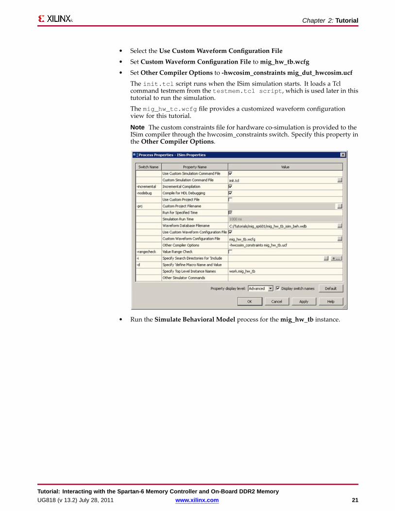
• Select the Use Custom Waveform Configuration File
• Set Custom Waveform Configuration File tomig_hw_tb.wcfg
• Set Other Compiler Options to -hwcosim_constraints mig_dut_hwcosim.ucf
The init.tcl script runs when the ISim simulation starts. It loads a Tclcommand testmem from the testmem.tcl script, which is used later in thistutorial to run the simulation.
The mig_hw_tc.wcfg file provides a customized waveform configurationview for this tutorial.
Note The custom constraints file for hardware co-simulation is provided to theISim compiler through the hwcosim_constraints switch. Specify this property inthe Other Compiler Options.
• Run the Simulate Behavioral Model process for themig_hw_tb instance.
Tutorial: Interacting with the Spartan-6 Memory Controller and On-Board DDR2 MemoryUG818 (v 13.2) July 28, 2011 www.xilinx.com 21

Chapter 2: Tutorial
Using the Fuse Command Line ToolYou can invoke the ISim compiler through the Fuse command line tool. As in the puresoftware simulation flow, you need to provide Fuse a project file, the design top levelmodule(s), and other optional arguments such as libraries to link in and library searchpaths. To compile the design for hardware co-simulation, you must provide the extraarguments listed below:
fuse -prj <project file> <top level modules>-hwcosim_instance <instance>-hwcosim_clock <clock>-hwcosim_board <board>-hwcosim_constraints <constraint file>-hwcosim_incremental <0|1>
• hwcosim_instance specifies the full hierarchical path of the instance to co-simulatein hardware
• hwcosim_clock specifies the port name of the clock input for the instance. This is theclock in the lock-step portion, which is to be controlled by the test bench.
For a design with multiple clocks, specify the fastest clock using this option so thatISim can optimize the simulation. Other clock ports are treated as regular data ports.
• hwcosim_board specifies the identifier of the hardware board to use forco-simulation. Two Spartan-6 boards are supported by default:
– sp601-jtag: Xilinx® SP601 Evaluation Platform
– sp605-jtag: Xilinx SP605 Evaluation Platform
• hwcosim_constraints (optional) specifies the custom constraints file that providesadditional constraints for implementing the instance for hardware co-simulation.We also use the constraints file to specify which ports of the instance are mapped toexternal I/Os or clocks.
• hwcosim_incremental (optional) specifies whether Fuse should reuse the lastgenerated hardware co-simulation bitstream and skip the implementation flow.
For example, to compile the EMAC design for this tutorial, you can run the Fusecommand line as follows:
fuse -prj mig_hw_tb.prj mig_hw_tb glbl-L unisims_ver –L secureip–o mig_hw_tb.exe-hwcosim_instance /mig_hw_tb/mig_inst-hwcosim_clock c3_clk0-hwcosim_board sp601-jtag-hwcosim_constraints mig_dut_hwcosim.ucf
Step 5: Running ISim Hardware Co-SimulationThe simulation executable generated by the ISim compiler runs in the same way inboth the pure software simulation and hardware co-simulation flow. Project Navigatorautomatically launches the simulation executable in GUI mode after the compilationfinishes.
In the Instances and Processes view, the instance selected for hardware co-simulation isindicated with a special icon . As the instance runs in hardware, you cannot expand itto see its internal signals and submodules.
Tutorial: Interacting with the Spartan-6 Memory Controller and On-Board DDR2 Memory22 www.xilinx.com UG818 (v 13.2) July 28, 2011

Chapter 2: Tutorial
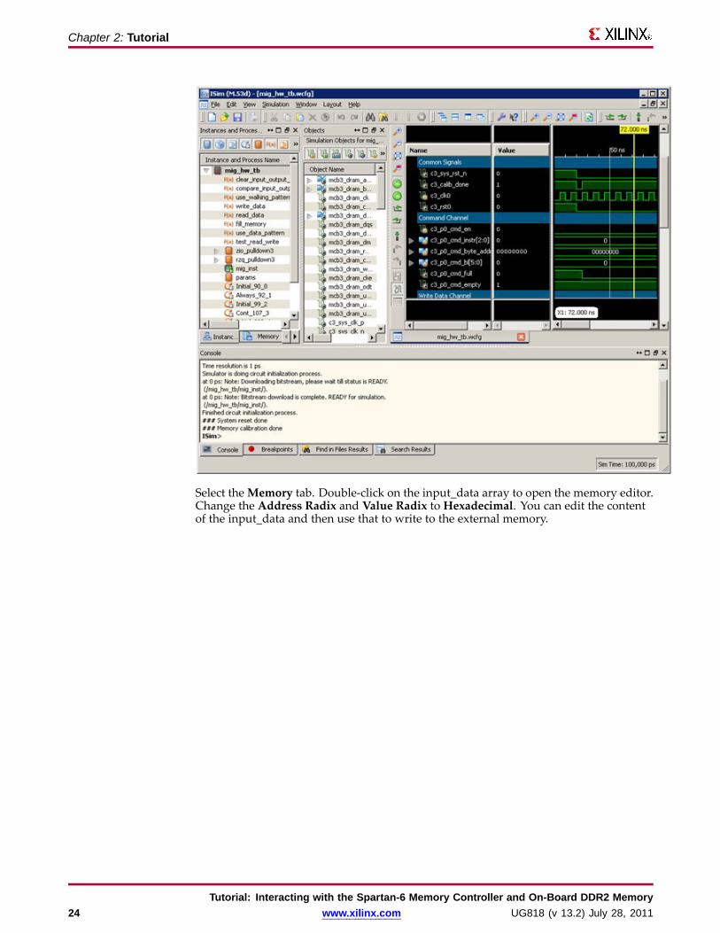
Before the simulation starts, ISim programs the FPGA with the bitstream file generatedfor hardware co-simulation. You might notice the message in the ISim consolewindow: “Downloading bitstream, please wait till status is READY”. Once the FPGAis configured, the console shows “Bitstream download is complete. READY forsimulation.” From this point, you can run the simulation and interact with the ISim GUIthe same way you do in the software simulation flow.
The test-bench initially resets the system by asserting the c3_sys_rst_n signal, whichthen triggers the memory calibration process. You should see the following messagesin the ISim console:
### System reset done### Memory calibration done
The c3_calib_done signal transitions from low to high after the reset is de-asserted. Thisis because the memory calibration process takes place in hardware at full speed. It takesa much longer time if the calibration process is simulated in software.
Tutorial: Interacting with the Spartan-6 Memory Controller and On-Board DDR2 MemoryUG818 (v 13.2) July 28, 2011 www.xilinx.com 23
Chapter 2: Tutorial
Select theMemory tab. Double-click on the input_data array to open the memory editor.Change the Address Radix and Value Radix to Hexadecimal. You can edit the contentof the input_data and then use that to write to the external memory.
Tutorial: Interacting with the Spartan-6 Memory Controller and On-Board DDR2 Memory24 www.xilinx.com UG818 (v 13.2) July 28, 2011

Chapter 2: Tutorial
Run “testmem 0 1024 0” in the ISim console. This triggers the test_memory taskin the test bench, which writes the data in input_data to the external memory startingfrom address 0 to 1024 and then reads the data back from the same memory region tooutput_data. You should see the following messages from the ISim console:
### Read/write test started... Writing 00000000... Reading 00000000==> No data mismatches found.### Read/write test done
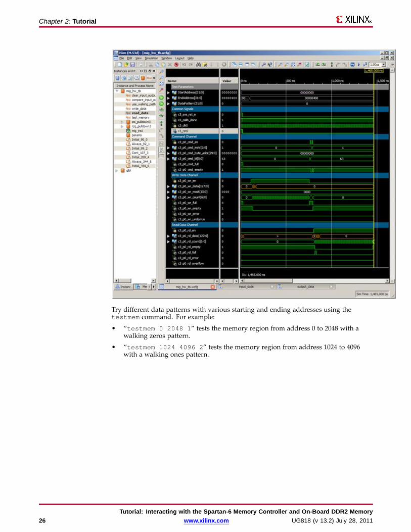
Observe the waveform of c3_p0_cmd_*, c3_p0_wr_*, and c3_p0_rd_* to seehow the test bench interacts with the MCB and how the MCB status signals (such asc3_p0_wr_count) changes during the memory write/read transaction.
Tutorial: Interacting with the Spartan-6 Memory Controller and On-Board DDR2 MemoryUG818 (v 13.2) July 28, 2011 www.xilinx.com 25
Chapter 2: Tutorial
Try different data patterns with various starting and ending addresses using thetestmem command. For example:
• “testmem 0 2048 1” tests the memory region from address 0 to 2048 with awalking zeros pattern.
• “testmem 1024 4096 2” tests the memory region from address 1024 to 4096with a walking ones pattern.
Tutorial: Interacting with the Spartan-6 Memory Controller and On-Board DDR2 Memory26 www.xilinx.com UG818 (v 13.2) July 28, 2011
Appendix
Additional Resources• Xilinx Glossary -
http://www.xilinx.com/support/documentation/sw_manuals/glossary.pdf
• Xilinx Documentation - http://www.xilinx.com/support/documentation
• Xilinx Support - http://www.xilinx.com/support
Tutorial: Interacting with the Spartan-6 Memory Controller and On-Board DDR2 MemoryUG818 (v 13.2) July 28, 2011 www.xilinx.com 27