xa9952141 iaea-tecdoc-1100iaea-tecdoc-1100 issn 1011-4289 ©iaea, 1999 printed by the iaea in...
TRANSCRIPT

IAEA-TECDOC-1100XA9952141
Survey of wet and dryspent fuel storage
INTERNATIONAL ATOMIC ENERGY AGENCY /A>
July 1999
3 0 - 3 8

The originating Section of this publication in the IAEA was:Nuclear Fuel Cycle and Materials Section
International Atomic Energy AgencyWagramer Strasse 5
P.O. Box 100A-1400 Vienna, Austria
The IAEA does not normally maintain stocks of reports in this series.However, copies of these reports on microfiche or in electronic form can be obtained from
IMS ClearinghouseInternational Atomic Energy AgencyWagramer Strasse 5P.O.Box 100A-1400 Vienna, AustriaE-mail: [email protected]: http://www.iaea.org/programmes/inis/inis.htm
Orders should be accompanied by prepayment of Austrian Schillings 100-in the form of a cheque or in the form of IAEA microfiche service couponswhich may be ordered separately from the INIS Clearinghouse.
SURVEY OF WET AND DRY SPENT FUEL STORAGEIAEA, VIENNA, 1999IAEA-TECDOC-1100
ISSN 1011-4289©IAEA, 1999
Printed by the IAEA in AustriaJuly 1999
FOREWORD
Spent fuel storage is one of the important stages in the nuclear fuel cycle and stands amongthe most vital challenges for countries operating nuclear power plants. Continuous attention isbeing given by the IAEA to the collection, analysis and exchange of information on spent fuelmanagement. Its role in this area is to provide a forum for exchanging information and for co-ordinating and encouraging closer co-operation among Member States. Spent fuelmanagement is recognized as a high priority IAEA activity.In 1997, the annual spent fuel arising from all types of power reactors worldwide amounted toabout 10 500 tonnes heavy metal (t HM). The total amount of spent fuel accumulatedworldwide at the end of 1997 was about 200 000 t HM of which about 130 000 t HM of spentfuel is presently being stored in at-reactor (AR) or away-from-reactor (APR) storage facilitiesawaiting either reprocessing or final disposal and 70 000 t HM has been reprocessed.Projections indicate that the cumulative amount generated by 2010 may surpass 340 0001 HMand by the year 2015 395 000 t HM. Part of the spent fuel will be reprocessed and somecountries took the option to dispose their spent fuel in a repository. Most countries withnuclear programmes are using the deferral of a decision approach, a 'wait and see' strategywith interim storage, which provides the ability to monitor the storage continuously and toretrieve the spent fuel later for either direct disposal or reprocessing. Some countries usedifferent approaches for different types of fuel. Today the worldwide reprocessing capacity isonly a fraction of the total spent fuel arising and since no final repository has yet beenconstructed, there will be an increasing demand for interim storage.The present survey contains information on the basic storage technologies and facility types,experience with wet and dry storage of spent fuel and international experience in spent fueltransport. The main aim is to provide spent fuel management policy making organizations,designers, scientists and spent fuel storage facility operators with the latest information onspent fuel storage technology under wet and dry conditions.The IAEA wishes to thank the working group which prepared this publication and all thosewho contributed to its preparation through their comments and participation in discussions.The IAEA officer responsible for this publication was P. Dyck of the Division of Nuclear Fuel Cycleand Waste Technology.

EDITORIAL NOTE
In preparing this publication for press, staff of the IAEA have made up the pages from theoriginal manuscript(s). The views expressed do not necessarily reflect those of the IAEA, thegovernments of the nominating Member States or the nominating organizations.
Throughout the text names of Member States are retained as they were when the text wascompiled.
The use of particular designations of countries or territories does not imply any judgement bythe publisher, the IAEA, as to the legal status of such countries or territories, of their authorities andinstitutions or of the delimitation of their boundaries.
The mention of names of specific companies or products (whether or not indicated asregistered) does not imply any intention to infringe proprietary rights, nor should it be construed asan endorsement or recommendation on the part of the IAEA.

CONTENTS
1. INTRODUCTION...............................................................................................................1
1.1. Backgrovmd.................................................................................................................!1.2. Scope...........................................................................................................................!
2. BASIC STORAGE TECHNOLOGIES AND FACILITY TYPES.....................................2
2.1. Introduction.................................................................................................................22.2. Wet storage.................................................................................................................22.3. Dry storage..................................................................................................................4
2.3.LVaults.................................................................................................................52.3.2. Container (cask and silo) systems.....................................................................6
3. EXPERIENCE WITH WET STORAGE OF SPENT FUEL..............................................8
3.1. Introduction.................................................................................................................83.2. At-reactor (AR) storage pools.....................................................................................8
3.2.1. Canada.............................................................................................................93.2.2. France............................................................................................................. 113.2.3. Germany.........................................................................................................113.2.4. Japan.............................................................................................................. 113.2.5. Russian Federation.........................................................................................123.2.6. United Kingdom............................................................................................ 123.2.7. USA...............................................................................................................13
3.3. Away-from-reactor (AFR) storage pools.................................................................. 133.3.1. Bulgaria.......................................................................................................... 133.3.2. Finland...........................................................................................................143.3.3. France............................................................................................................. 153.3.4. Germany.........................................................................................................173.3.5. India............................................................................................................... 173.3.6. Japan.............................................................................................................. 183.3.7. Russian Federation.........................................................................................193.3.8. Slovakia.........................................................................................................233.3.9. Sweden...........................................................................................................243.3.lO.United Kingdom ............................................................................................263.3.ILUkraine...........................................................................................................283.3.12.USA...............................................................................................................28
4. EXPERIENCE WITH DRY STORAGE OF SPENT FUEL ............................................29
4.1. Introduction...............................................................................................................294.2. Vault facilities...........................................................................................................30
4.2.1. Canada ............................................................................................................304.2.2. France.............................................................................................................324.2.3. Hungary...........................................................................................................344.2.4. United Kingdom ............................................................................................364.2.5. USA...............................................................................................................37
4.3. Cask facilities............................................................................................................394.3.1. Cask facilities in operation ............................................................................39
4.3.2. Cask facilities under licensing and construction............................................504.4. Silo facilities.............................................................................................................53
4.4.1. Silo facilities in operation..............................................................................534.4.2. Silo facilities under licensing and construction in the USA ..........................62
5. TRANSPORTATION OF SPENT FUEL .........................................................................63
5.1. Introduction...............................................................................................................635.2. Interim storage location ............................................................................................635.3. Recent developments................................................................................................635.4. International experience in spent fuel transport........................................................63
APPENDICES A-C
Appendix A: Multi-element bottles ........................................................................................69Appendix B: Rod consolidation at BNFL...............................................................................71Appendix C: Container descriptions.......................................................................................72
REFERENCES.........................................................................................................................95
DEFINITIONS.........................................................................................................................^?
CONTRIBUTORS TO DRAFTING AND REVIEW ............................................................ 101

1. INTRODUCTION
1.1. Background
The IAEA conducted a survey between 1978 and 1980 to collect and summarise informationon extended water pool storage in which there was increasing interest. Many utilities couldperceive a shortage of storage capacity and only a limited amount of reprocessing capacity.The results of this survey were published in 1982 in Ref. [1].hi 1986, the IAEA considered it was timely to conduct a survey on the emerging field of drystorage and to update the data on wet storage. A considerable amount of R&D was being con-ducted in the field of dry storage. The results of the survey were published in 1988 in Ref. [2]and gave a detailed assessment of dry storage technology and the associated R&D.hi the period since 1986 very significant progress has been made in dry storage technologyand a number of commercial facilities have been commissioned. There have also been anumber of large pools constructed but these have largely been central facilities associated withreprocessing facilities or as interim storage for disposal.The purpose of this report is to collect and describe the worldwide experience that has beengained over the last decade with the storage of spent nuclear fuel. There is no intention to giveguidelines regarding the selection of technologies for storage of spent nuclear fuel, as differentproven technologies are now available. The selection process has to take into account differentcriteria (e.g. quantity of fuel, cost of the technology, fuel management options, and individualcircumstances) resulting in an optimum system in terms of technology, economics, timetableetc.International experience with the storage of spent fuel is described in Sections 3 and 4 for wetand dry storage, respectively. Section 5 covers the subject of transportation of spent fuel as theSurvey is considered to be a convenient way of incorporating experience in transport.
1.2. Scope
The scope of this report is to review the current technology for storage of spent fuel frompower reactors. Storage of fuel from research reactors is not considered. The information anddata included has been derived directly from Member States where possible, from a review ofprevious documentation and from published documents from various sources made availableto the IAEA.Comprehensive information is not available on the storage of spent nuclear fuel in at-reactor(AR) operational pools. Many of these are now designed for plant lifetime arisings at newNPPs and can be considered as a form of interim storage. The spent fuel pool inventory can beobtained by inference from total fuel arisings and the quantity sent for reprocessing. Rodconsolidation, as a means of increasing spent fuel storage capacity, is referred to briefly as thistechnique has not been taken up in spite of intense interest in the 1980s. Information on thistechnique can be found in Annex G of Ref. [2].Away-from-reactor (APR) spent fuel storage is dealt with in some detail and a distinction ismade between storage on the reactor site (RS) and storage off site (OS).The survey was conducted by a group of international consultants and presented to a largeradvisory committee for review. Three consultants worked to finish the draft report inDecember 1997. In 1998 some additional data and information were included.

2. BASIC STORAGE TECHNOLOGIES AND FACILITY TYPES
2.1. Introduction
Virtually all power reactors have some form of spent fuel pools associated with the reactoroperations. AR has, in recent years, been used to full capacity in some cases, threatening thecontinued operation of the power plant. Recent designs of reactors have in fact nowincorporated pools that can accommodate lifetime arisings over periods of up to 40 years.However, most older operational plants, due to their limited AR capacity have necessitated thedevelopment of APR storage.Two technologies have been developed for APR storage. Initially the storage method was wetbut in recent decades dry storage techniques of varying types have been developed. AFRstorage can be considered in two categories. The first is where additional interim storagecapacity is constructed at the reactor site (RS) but largely or entirely independent of thereactor and its AR pool. This AFR (RS) storage can be wet in the form of secondary oradditional pools or most often in the form of dry storage facilities which may or may not havecapability for off-site transport. It has been suggested that some of these AFR (RS) facilitiesmay stay operational well beyond the life of the power plant (up to 50 or 100 years).The second category of AFR storage is off the reactor site (OS) at an independent location. Alarge proportion of this AFR (OS) capacity is in the form of pools at reprocessing plantsparticularly in France, the UK and The Russian Federation. AFR (OS) interim storage can alsobe centrally located at a selected power plant complex and receive fuel from other powerplants. So far there are no AFR (OS) facilities at proposed repository sites. By far the majorityof AFR storage capacity is wet (approx. 92%) with only the remaining 8% in dry storage.Both wet and dry storage technologies have to address the following requirements:(1) Fuel cladding integrity should be maintained during handling and exposure to corrosion
effects of the storage environment(2) Fuel degradation during storage should be prevented through providing adequate
cooling in order not to exceed fuel temperature limits.(3) Subcriticality of the spent fuel is to be maintained under normal and accidental
conditions.(4) Radiological shielding of the spent fuel should protect plant operators, the public and
the environment from receiving radiation doses in excess of regulatory limits.(5) Environmental protection should be assured by minimising the release of radioisotopes.(6) Fuel retrievability must always be available.
2.2. Wet storage
As already discussed, wet storage is implemented in AR and AFR storage facilities.AR facilities are essentially storage pools in which spent fuel is kept under water followingdischarge from the reactor. Most AR storage pools have been built at the same time as thereactor and are fully integrated with the reactor operation. Thus experience with AR wetstorage is available for more than 30 years and is not described in this section.There is a variety of AFR wet storage facilities in use. Some provide extended operationalcapacity to reactors once their AR pool is full of spent fuel, and may or may not be built atreactor site.
A typical APR wet storage facility may have the following features:— Cask reception, decontamination, unloading, maintenance and dispatch;— Underwater spent fuel storage (pool);— Auxiliary services (radiation monitoring, water cooling and purification, solid
radioactive waste handling, ventilation, power supply etc.).
Spent fuel is received (either wet or dry) at the ARF facility contained in a transport cask. Fuelmay be removed either assembly by assembly or in a multi-element canister. Two types ofcask unloading method are in operation: wet and dry. The wet unloading, being the initiallydeveloped type for LWR spent fuel, is performed under water. A hot cell type facility is usedfor dry unloading.
The storage pool is a reinforced concrete structure usually built above ground or at least atground elevation, however, one wholly underground facility is in operation. Some early poolswere open to the atmosphere, but operational experience and the need to control pool waterpurity has resulted in all pools now being covered. The reinforced concrete structure of thepool, including the covering building, needs to be seismically qualified depending uponnational requirements.Most pools are stainless steel lined, some are coated with epoxy resin based paint. However,there has been experience with degradation of the latter after a number of years. A furtheroption is for the pond to be unlined and untreated. In some situations the pool may be stainlesssteel lined or epoxy treated only at the water line or at other locations.Regarding unlined and untreated pools, properly selected and applied concrete proved to havenegligible corrosive ion leaching and permeability to water.The pools are filled with deionized water with or without additive addition depending on thetype of fuel to be stored and the adopted method of treatment. The water is either a fixedquantity or a once through pond purge. Water activity levels are maintained ALARA (as lowas reasonably achievable) by either in-pool or external ion exchange systems or by limitingactivity release to the bulk pool water.Leakage from the pool is monitored, either by means of an integrated leakage collectionsystem or via the interspace in pools with two walls. In both cases any recovered pool watermay be cleaned up and returned to the main pool.In addition to the control of activity by ion exchange or purge, some pools are operated withan imposed chemical regime. This is for pH control, maintaining boron levels for criticalitycontrol where necessary, and the maintenance of acceptably low levels of aggressive anionssuch as chloride and sulphate to minimise fuel degradation. Maintenance of good waterchemistry provides good water clarity and usually prevents the occurrence of micro-biologicalorganisms. If these do occur, they are treated with specific chemical dosing.There are also two methods in regular use allowing fuel to be isolated from the bulk poolwater; namely by using single or multi-element bottles, or storage containers.Subcriticaliry was originally maintained for LWR spent fuel (assumed to be fresh) by spacingwithin the storage racks or baskets. However with the need to store greater quantities of fuel,higher storage density has been achieved by the introduction of neutron absorbing materials instorage racks and baskets such as boronated stainless steel, boral or boraflex.The period of time that spent fuel resides in a pool varies between pools (AR and APR) andthe requirements of the overall spent fuel management system. Some Zircaloy clad fuel hasbeen wet stored satisfactorily for over 40 years.

The survey results of the AFR wet storage experience are given in Table I. The number offacilities and total design capacities are given along with the approximate current inventoriesas of 1997.
TABLE I. SUMMARY OF WORLDWIDE AWAY-FROM-REACTOR (AFR) WET SPENTFUEL STORAGE
Member State
ArgentinaBelgiumBulgariaFinlandFranceGermanyIndiaJapanRussian FederationSlovakiaSwedenUkraineUnited KingdomUnited States of AmericaTOTAL
Number offacilities
11124113611141
28
AFR pools in operationDesign capacity
tHM110010006001450
1450056027
430012960
60050002000
10350780
55227
Current inventorytHM76635
356700
915952627
35006046523
270316957031700
33767
2.3. Dry storage
Development work and progress on a variety of dry storage technologies has been intensiveover the last decade. For practical and economic reasons, various dry spent fuel storagetechnologies were developed to meet specific requirements of different reactor fuels; e.g.maximum allowable cladding temperature, cover gas environment (air, COz, or helium). Drystorage facilities operating or under construction in the Member States are listed in Table n, asof end of 1997.Initially dry storage were single purpose systems. They only provided AFR (RS) storage (withone exception represented by Wylfa Dry Stores, which is also an AR facility) without thecapability or authorisation for eventual transport off site (without rehandling and reloading thefuel into transport casks). Vaults, silos and non-transportable casks are single purposesystems. With continuing development of dry storage technology, it was recognised that casksand containers for encapsulating the fuel could perform multiple functions. Dual purposecasks were developed (e.g. CASTOR cask in Germany, TN 24 in Belgium and the NAC-STCin USA) which allowed storage and transport to and from a storage facility without rehandlingof fuel assemblies. The fuel containers of some storage systems may be used for transportand/or final disposal. These are often referred to as dual- or multi-purpose systems,respectively.

TABLE H. SUMMARY OF WORLDWIDE DRY SPENT FUEL STORAGE
Member State
ArgentinaBelgiumCanada
OperatingConstruction
Czech RepublicFranceGermany
OperatingConstruction
HungaryJapanRepublic of Korea
OperatingConstruction
LithuaniaUkraineUnited KingdomUSA
operatingconstruction
TOTAL
Number offacilities
]1
71I
1
3111
11111
106
39
Design capacitytHM200800
856714500
600
180
7768585162'73
60981241950
958
47002155
43 138
Current inventorytHM
64142
1930-
232
180
58-
5473
609000
680
1270
5292
2.3.1. Vaults
Vaults consist of above- or below-ground reinforced concrete buildings containing arrays ofstorage cavities suitable for containment of one or more fuel units. Shielding is provided bythe exterior structure. Heat removal is normally accomplished by forced or natural convectionof air or gas over the exterior of the fuel containing units or storage cavities, and subsequentlyexhausting this air directly to the outside atmosphere or dissipating the heat via a secondaryheat removal system.
Typical features of vaults are their modularity, which facilitates incremental capacityextension, separated shielding and containment functions, capability for containmentmonitoring, and a vertical fuel loading methodology.
1 Phase 1.

Spent fuel is received (either dry or wet) at a vault facility using transfer or transportationcasks. Spent fuel is removed from the transfer or transportation casks, prepared for storage ifneeded, and placed in a metal storage tube (single fuel element) or a storage cylinder (singleor multi-element canister) which is housed within a concrete storage cavity in the vaultstructure. The storage tubes or storage cylinders are sealed and may be backfilled with an inertgas to improve heat transfer from the fuel and prevent oxidation of spent fuel while in storage.They are usually fitted with connections to a continuous or periodic monitoring system.In vaults using metal storage tubes the transfer of uncontainerised fuel assemblies is carriedout, following drying if required, one by one directly into their storage location. Typicalcomponents of this type of storage facility are the vault modules, the fuel handling machineoperating in the charge hall, the cask receiving area and the auxiliary facilities (areas for plantcontrol, maintenance, services, offices etc.). Examples are the MVDS facility at Paks inHungary and the Magnox Dry Storage Facility at the Wylfa reactor in the UK.Vaults using storage cylinders receive the fuel already sealed in containers (the MACSTORsystem CANSTOR application at Gentilly 2 NPP in Canada, the CASCAD facility in France,or Fort St. Vrain MVDS in the USA). These types of vault facilities use a transfer caskhandled by crane. The container transfer into the storage cylinder is either performed remotely(CASCAD) or with operator assistance (Fort St. Vrain and Gentilly 2).
2.3.2. Container (cask and silo) systems
A container is a receptacle to hold spent fuel to facilitate movement and storage or eventualdisposal, according to the IAEA glossary of spent fuel terms [3]. Metal casks, concrete casksand silos are variations of the container storage systems. There is a large variety of containersystem designs used for storage of spent fuel.The following features are common to all cask and silo designs:Casks or silos are modular in nature. These systems are sealed systems with no radioactiverelease from the casks or silos during storage. A storage cask or silo provides shielding andcontainment of the spent fuel by physical barriers which may include the metal or concretebody and metal liner or metal canister and lids. They are usually circular in cross-section, withthe long axis being either vertical or horizontal. Fuel position is maintained inside a storagebasket which may or may not be an integral part of the container. Heat is removed from thestored fuel by conduction or natural convection to the surrounding environment. Casks orsilos may be enclosed in buildings or stored in an open area.A cask or silo storage facility may include cask handling equipment, fuel handling equipment,decontamination equipment, radiation protection, and leak tightness monitoring equipment.Cask or silo storage facilities may not be independent of reactor services and may depend oncask handling, fuel handling and decontamination equipment from the reactor.Some features that may vary between the technologies are structural material, transportability(dual or multi-purpose), fuel loading orientation, storage orientation (horizontal or vertical).Individual systems may or may not be monitored for leak tightness.
2.3.2.1. Metal casks
Metal casks are massive containers used in transport, storage and eventual disposal of spentfuel. The structural materials for metal casks may be forged steel, nodular cast iron, or asteel/lead sandwich structure. They are fitted with an internal basket or sealed metal canisterwhich provides structural strength as well as assures subcriticality. Metal casks usually have a
double lid closure system that may be bolted or seal welded and may be monitored for leaktightness.Metal casks are usually transferred directly from the fuel loading area to the storage site. Somemetal casks are licensed for both storage and off-site transportation. Fuel is loaded verticallyinto the casks which are usually stored in a vertical position.Metal casks used in a number of countries such as Germany, the USA, the Czech Republic andSwitzerland; Transnucleaire's TN-40 metal casks used in the USA; Westinghouse MC-10 caskused in the USA; and Nuclear Assurance Corporation's metal cask designs used in the USAand Spain.
2.3.2.2. Concrete casks
Concrete casks are moveable structures with one storage cavity. They are used in storage, andin some cases, transport of spent fuel. Structural strength and radiological shielding areprovided by reinforced regular or high density concrete.Concrete cask systems may use sealed metal canisters housed inside the concrete storage caskto contain spent fuel. The metal canister may be cooled by natural convection of the ambientair and use a double lid closure system.Sealed metal canisters may be contained in an on-site transfer cask for loading spent fuel fromthe fuel loading station and for transfer to the concrete storage cask.Spent fuel may also be loaded directly into a concrete cask in the fuel loading station and theconcrete cask would be transferred directly to the storage site. Some sealed metal canistersmay be licensed for transportation as part of an off-site transportation package.Alternatively, concrete cask systems may use a metal liner in the cask cavity to contain spentfuel and a single lid closure system. Heat transfer may take place solely by conduction throughthe concrete structure.Concrete casks that rely on conductive heat transfer have more thermal limitations than thoseusing natural convection air passages.Fuel is loaded vertically into the concrete casks and the concrete cask systems are stored in avertical orientation.Concrete casks use single or double lid closure systems, are welded closed, and tested for leaktightness. Concrete cask systems may or may not be monitored for leak tightness.Examples of vertical concrete casks include Sierra Nuclear's VSC cask; and Ontario Hydro'sPickering concrete dry storage container which is also designed for off site transport.
2.3.2.3. Silos
Silo systems are monolithic or modular concrete reinforced structures. The concrete providesshielding while containment is provided by either an integral inner metal vessel (liner), whichcan be sealed after fuel loading, or by a separate sealed metal canister. In silos, spent fuel maybe stored in vertical or horizontal orientation. Fuel loading into silos always takes place at thestorage site.A typical example of a silo system is AECL's concrete canister, which is built on-site usingregular reinforced concrete and is fitted with a steel inner liner. Spent fuel is transferred inincrements within sealed baskets using a shielded transfer cask and loaded vertically. Once

loading operations are complete, a closure shield plug is placed and welded to the inner linerto provide additional containment.The NUHOMS storage system is an example of a horizontal concrete silo system. Fuel isloaded vertically into metal canisters which are stored in a horizontal orientation insideconcrete storage modules. The sealed metal canister is contained in an on-site transfer cask forloading spent fuel from the fuel loading station and for transfer to the horizontal concretestorage module. The metal canisters are fitted with a double lid closure system, whichfollowing welding is tested for leak tightness. Some sealed metal canisters may be licensed fortransportation as part of a transportation package. The system is not monitored for leaktightness.
3. EXPERIENCE WITH WET STORAGE OF SPENT FUEL
3.1. Introduction
This section outlines and documents the experience on wet storage.Storage pool experience exists for both AR and APR technologies. While AR pool storage iscommon to all reactors in order to provide cooling following discharge from the reactor, APRpool storage is an option for additional spent fuel storage prior to disposal or reprocessing.The information on AR pools is not complete but some representative examples from someMember States have been included. The quantity of fuel storage in AR pools is difficult todetermine because the inventory varies with reactor refuelling cycles and the amounttransferred to AFR storage and reprocessing. In general, AR pools are never operated to fulldesign capacity because of a need to provide some buffer storage capacity for operationalreasons. Since the last survey completed in 1988, approximately 40 power reactors withrelated AR storage pools have been commissioned. The variety of solutions for AFR poolstorage gives a wide range of experience. AFR pool facilities are subdivided into pools inoperation, under licensing and construction.Positive experience on the storage of spent fuel in pools has been collected over more than 30years. It can now be predicted that Zircaloy clad fuel integrity will be maintained even after 50years of wet storage. Monitoring and surveillance have confirmed that adherence to thespecified pool water chemistry is essential to prevent fuel cladding degradation during poolstorage for all types of spent fuel. Even if the fuel assembly contains defects incurred duringirradiation, it can be stored in pools for extended periods. It may even be that a poolcomponent could, in some cases, be more life limiting than the fuel assembly itself.In conclusion it can be stated, that wet storage of spent fuel is a proven technology, which canmeet all storage requirements through proper engineering. The experience, which has beenreported using different facilities, is described in this section.
3.2. At-reactor (AR) storage pools
At-reactor spent fuel storage pools are either within the reactor building or in an adjacentspent fuel building which is linked to the reactor by a transfer tunnel. Access to the fuel in thestorage pool is usually by means of immersing a cask in the pool, loading it with fuel and thenremoving the cask for lid closure, decontamination and transport. A recent development,unique to France, is a cask loading concept with bottom access ports from the pool for fueltransfer into the cask. The advantages of this design are that contamination of the externalsurface of the flask by immersion in the pool is avoided, and also the requirement to lift the
flask (empty and loaded) between the inlet/outlet location and the pool and a heavy duty craneis no longer needed. There are some cases, for example at gas cooled reactors and at Sellafieldin the UK, where spent fuel is loaded into casks in a dry shielded cave and the cask is neverimmersed in water.The capacity of AR wet storage pools varies between countries and is a function of the overallfuel management strategy at the time the facility was built. The extremes are modest storagecapacity for short term buffer storage before transport off-site, to capacity sufficient to store asignificant proportion of the reactor lifetime arisings. The latter is generally the result of thedeferral by a country on decisions for reprocessing or disposal. In addition there will be arequirement to reserve space for full or part core inventory. This capacity for whole coredischarge would be separately identified as part of plant operations and is not considered partof AR interim spent fuel storage. In addition, new fuel or partly utilised fuel could betemporarily stored in the pool as part of plant operating inventory and would reduce the netcapacity available for AR storage.All AR storage pools require some form of water purity and chemical control to minimise theeffects of corrosion and the build up of activity in the water. This is potentially important forlong periods of storage and would be augmented by data from research and inspection. Themajority of fuel in wet storage is from water cooled reactors and is clad in zirconium basedalloy. The experience has been good and potential mechanisms for corrosion or degradationare understood. With water reactor fuel, removal from the transport flask or other containercan sometimes result in release of active particulate material (crud) into the pool water. Thisdepends largely on the fuel history in the reactor.AR wet storage summarised in Table III.
3.2.1. Canada
Experience with wet storage of spent fuel goes back to the early 1950s. Canadian in-pool wetstorage technology was initially developed at Chalk River Laboratories. The same technologyis applied to store fuel from CANDU prototype and power reactors.In Canada neither recycling nor reprocessing are planned for spent CANDU fuel. A permanentdisposal system is currently being developed. Consequently, AR interim wet storage facilitiesare expected to remain operational until fuel shipment to the disposal centre is complete(around 2035).CANDU reactors have a variety of pool designs and storage capacity. Single unit stations areusually provided with a single pool. The storage capacity is based on 10 years of reactoroperation.Ontario Hydro's multi-unit stations usually have primary and secondary storage pools. Thewater filled, reinforced concrete pools are built in and out of ground and are fitted with epoxyor stainless steel liners.Spent fuel bundles are horizontally stored in the pool in receptacles of different designs.Storage trays accommodate up to 24 bundles in a single layer. Trays are stackedapproximately 19 high in groups of two to four. Each group of stacks is provided with a coverthat is held in place by vertical rods that retain the stacks together to resist seismic loads andfor safeguards reasons.At Ontario Hydro's Pickering and Darlington reactor sites, spent fuel is stored in rectangularmodules containing 96 fuel bundles. The modules are equipped with wire mesh along thesides and are stored in frames for seismic restraint and safeguards purposes.
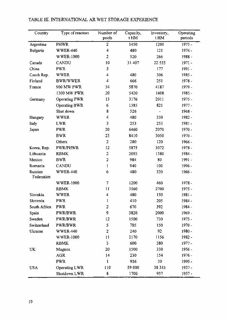
TABLE HI. INTERNATIONAL AR WET STORAGE EXPERIENCE
Country
ArgentinaBulgaria
CanadaChinaCzech Rep.FinlandFrance
Germany
HungaryItalyJapan
Korea, Rep.LithuaniaMexicoRomaniaRussian
Federation
SlovakiaSloveniaSouth AfricaSpainSwedenSwitzerlandUkraine
UK
USA
Type of reactors
PHWRWWER-440WWER-1000CANDUPWRWWERBWR/WWER900 MW PWR1300 MW PWROperating PWROperating BWRShut downWWERLWRPWRBWROthersPWR/PHWRRBMKBWRCANDUWWER-440
WWER-1000RBMKWWERPWRPWRPWR/BWRPWR/BWRPWR/BWRWWER-440WWER-1000RBMKMagnoxAGRPWROperating LWRShutdown LWR
Number ofpools
242103443420136843
20232122216
71141291252113
20141
1108
Capacity,tHM1450480520
31 407
480666
58705420317613855264802536460841028058752093984940480
1200356048041067038201500705240
21706001500230936
590001700
Inventory,tHM1200121266
22555177306251
418716082011821
-350253
20703050120
3072138080100320
4602700150205392200073015092
115638033015430
38343957
Operatingperiods1975-1974-1988-1971 -1991-1985-1978-1979-1985-1975-1977-1968-1982-1981 -1970-1970-1966-1978-1984-1991 -1996-1966-
1978-1975-1981-1984-1984-1969-1973-1970-1980-1982-1977-1956-1976-1995-1957-1957-
10
Fuel handling is currently a manual operation in most instances. Fuel loading into the storagemodules is performed remotely underwater. Special tools are used to manipulate bundles andtrays from a travelling bridge over the pool.Three CANDU prototype reactors are decommissioned including the pool facilities. AtDouglas Point, the stainless steel lined pool has been completely decontaminated. Allauxiliary systems are kept operational. At Gentilly-1, the epoxy lined pool is completely cleanfollowing drainage and removal of contaminated concrete surfaces. The entire area isconverted into office space. The NPD reactor pool (stainless steel lined) is drained, partiallydecontaminated and kept under surveillance.
3.2.2. France
The back end of fuel cycle policy implemented in France (based on reprocessing, plutoniumand uranium recycling through MOX and RepU fuels), has resulted in the French utility EDFestablishing a management practice to reprocess the U02 fuels first (after a suitable coolingperiod) while storing the MOX and RepU spent fuels for a period of time not defined yet.AR storage capacities are needed at each reactor site in order to secure a cooling period fordischarged fuel awaiting transportation to the reprocessing plant.
3.2.3. Germany
The German spent fuel management policy was primarily based on reprocessing until 1994.Reprocessing was mandatory by German atomic law. Exceptions were permitted ifreprocessing was not available or not economically feasible e.g. in the case of the HTR pebblebed spent fuel.A law was passed in 1994 by parliament which allowed direct disposal as an equivalentoption. The choice is left to the utilities operating the NPPs.AH NPPs are equipped with AR storage pools. The technical design is in accordance withproven international standards. The capacity and geometry vary from plant to plant. Morerecent plants tend to have larger storage capacity in order to improve the flexibility of spentfuel management.
3.2.4. Japan
Most of the spent fuel in Japan is stored in AR pools and amounts to 5200 t HM. This is onlyabout 1/3 of the total AR design capacity. Some of the fuel, amounting to over68001 HM including PWR, BWR and Magnox, has been sent for reprocessing in the UK andFrance. 1000 t HM has been sent to the Tokai facility. A small amount has been put into anew cask storage at Fukushima and amounts to 73 t HM. Some AR facilities currently havevery small quantities of fuel in storage or none.Experience with wet storage of spent fuel has been good and extends over about 31 years(1966-1997). No defected fuel has been reported nor any serious incidents with storagefacilities.Breeder reactor fuel has also been stored since 1996 and no problems have been reported.Currently 88 t HM of fast reactor fuel is in AR storage.
11

3.2.5. Russian Federation
Following is a brief description of standard AR facility constructions and operation.The WWER-440 AR storage period is normally up to 3 years. The storage pool is situated inthe main hall of the reactor unit in the vicinity of the reactor.The storage capacity of standard AR pools at WWER-440 reactors is designed for 2 full cores.One half (about 350 assemblies) was originally designed for normal reloads and the upperracks are used for emergency discharge from the reactor. Fuel is stored in racks at a spacing of225 mm in a triangular arrangement. (Some WWER-440 pools in other countries wentthrough a reracking which resulted in doubling the capacity).The construction of the AR storage pool for WWER-1000 fuel is somewhat different than forWWER-440 reactors. The storage pool with a total volume of 1100 m3 consists of 3 bays. Thefirst bay and one half of the second bay are occupied by the rack for spent fuel, while the otherhalf of the second bay is used for storing new (unirradiated) fuel. The third bay is a reserve foremergency core discharge. The total capacity of the pool is designed on the requirement toaccommodate 2.5 full cores (three yearly discharges in a 2 year fuel cycle plus one emergencycore discharge totalling 165 t HM). Fuel is stored in racks with a spacing of 400 mm in atriangular arrangement.The AR storage pool for RBMK-1000 fuel is situated in the main reactor hall in the vicinity ofthe reactor. The pool consists of 2 independent bays, each having the volume of 750 m3. Thedesign capacity of each bay is for 850 fuel assemblies stored in separate cans filed withdemineralised water. Reloading operations are performed by a special reloading machine atthe operating reactor. Spent fuel placement in a storage position is by means of a It hoistwhich has a restricted lifting height to ensure that the fuel remains under a shielding waterlayer at all times. The loaded cans are hung between beams spaced at 250 mm at the level ofthe metal deck of the pool hall. Fuel assemblies are spaced at 160 mm.The BN-600 fuel is also stored in water pools. Reloading operations are performed at the shut- down reactor during planned maintenance and repair works. A dry reloading mode is used,with the reloading equipment located in the reactor vessel and in reloading boxes orcontainers. Inert gas atmosphere in the containers provides safe reloading of fuel with tracesof sodium coolant.
3.2.6. United Kingdom
In the UK no problems have been experienced with interim storage of AGR stainless steelclad fuel in station spent fuel storage pools. Fuel is stored in open topped skips and as it iscurrently all committed to reprocessing, the storage period is not long usually less than a yearbut cooled for about 120 days before transport. The pools have reserve capacity for a wholecore discharge. The pools have the usual capability for recirculation, cooling and filtration.Magnox fuel storage in AR pools is also satisfactory with the fuel elements stored in opentopped skips. Magnox cladding cannot dwell in water for long periods and the fuel is usuallyshipped for reprocessing after a cooling period of about 120 days.As with its American counter parts of more recent design, Sizewell B has been designed tominimise the stations dependency on the back end of the nuclear fuel cycle. Initially designedto accommodate up to a thousand fuel assemblies approximately 18 years of operation,capacity is currently being reviewed by investigation of fuel densification systems. Sizewell Bwas commissioned in 1995 and has discharged its first fuel to the AR pool.
12
3.2.7. USA
The majority of spent nuclear fuel arisings in the USA are stored in at-reactor spent fuelstorage pools. At the end of 1997, 110 operating and 9 shutdown reactors had approximately35 500 MTU of spent nuclear fuel in storage in operating reactor AR pools and 1000 MTU inshutdown reactor pools. Approximately 1300 MTU of spent fuel is stored in dry storagefacilities.The current licensed AR wet storage capacity in the USA is approximately210 000 spent fuel assemblies, corresponding to approximately 61 000 MTU. However, theexcess of total maximum capacity over current total inventory does not reflect the shortage ofpool storage capacity that occurs in individual reactor cases. For example, shutdown reactorpools had a capacity of 5800 assemblies or approximately 1700 MTU. The majority of reactorspent fuel storage pools have been reracked once, and some several times, to increase in-poolstorage capacity. Reracking of spent fuel storage pools is now only available to a smallremaining number of US reactors as a means of increasing storage capacity [4].Currently, 14 reactors have exhausted AR pool capacity and have had to construct dry storagefacilities. Of the 110 operating reactors in the USA, approximately 27 reactors are projected torun out of in-pool spent fuel storage capacity by 1998.
3.3. Away-from-reactor (APR) storage pools
Away-from-reactor pools constitute the largest volume of interim spent fuel storage. They aredivided into pools at the reactor site (RS) and pools away from the reactor site or off site (OS).The distinction between the RS and OS categories is clear but this is not always as clear inclassifying At-reactor and Away-from-reactor storage pools. True AFR(RS) pools areindependent of the reactor and all its services and can continue to operate after the reactor hasbeen finally shut down and decommissioned. There are pools, however, that are truly APRtypes but rely extensively on reactor services such as cooling water and water treatment,ventilation and electrical supplies (e.g. Loviisa, Pickering). In fact, nearly all AFR(RS) poolsare dependent on the reactor systems to some extent and certainly for staff and operatingmanagement. When reactors are shut down, special arrangements will have to be takenbecause it could be impractical or uneconomic to continue to operate costly reactor derivedservices if the fuel must remain in storage for long periods. Many of the AFR(RS) facilitieshave been provided at older power plants because these AR pools are often not large nor sizedfor lifetime arisings.AFR(OS) interim storage facilities on the other hand are most often associated withreprocessing plants (La Hague, Sellafield, Cheljabinsk and Rokkasho Mura in the future) butsometimes for direct disposal (e.g. CLAB in Sweden).
3.3.1. Bulgaria
Bulgaria has one AFR(RS) facility located at Kozloduy NPP.Proposed in 1974 as an alternative to spent fuel transportation to the USSR, construction ofKozloduy AFR(RS) facility did not began until 1982. The first fuel receipts to this facilitywere made on the 28th February 1990.The facility was the first of a proposed common design for an APR at the Soviet built reactorsto store WWER fuel and it comprises of fuel receipt, unloading and storage areas. The currentdesign is slightly different from the other facilities in that respect that this was meant for the
13

long-term storage of 168 baskets (4920 assemblies, -600 t HM) of spent fuel from the sitesfour WWER-440 and two WWER-1000 reactors; to be loaded over a period often years.After cooling for 3 years in the AR storage pools, the assemblies are transported to theAFR(RS) by an on-site transport container and a specialised trailer unit. Yearly receipts are atthe rate of 25 transport baskets comprised of 4 baskets or 120 fuel assemblies per WWER-440reactor and 9 baskets or 108 fuel assemblies from the two WWER-1000 units.The storage area is made up of three operational water bays and a contingency bay to allow forpreventive maintenance/provision against major in-bay failure. To afford this storage bays canbe isolated from the one another by hydraulic seals/gates, and leak monitoring equipment isprovided at the pool lining inter space. All pools are doubled lined with carbon and stainlesssteel.Spent fuel from the WWER-440 reactors is stored in transport baskets (containing 30 fuelassemblies (FA) with intact fuel cladding or 18 bottled fuel assemblies where the cladding isleaking). WWER-1000 spent fuel is stored in transport baskets. The capacity of the baskets is:12 intact fuel assemblies, or 6 bottles of failed fuel.Storage temperature is maintained below 45°C in the spent fuel compartments which areprovided with automatic continuous monitoring of feedwater, overflow, and permissible highand low water levels.
3.3.2. Finland
Finland has two AFR(RS) facilities located at Loviisa and Olkiluoto NPPs.
3.3.2.1. Loviisa AFR(RS)
Phase 1 of the Loviisa AFR(RS) was brought into operation in 1980 increasing the storagecapacity of the unit 1 NPP to take account of a need for increased fuel cooling from 3-5 yearsprior to transport/reprocessing in the Soviet Union. The APR was later extended to 1984(phase 2) to provide additional storage capacity for unit 2 of the NPP (see Fig. 1).The two phases of the AFR were built alongside one another three metres below ground. Theservices for each phase are provided by the associated unit of the NPP.Phase 1 comprises two parallel storage bays, a loading bay, a decontamination well for casks,a dry burial ground for control rods, and a lid deck under which the cask transport vehicles arelocated. The storage bays are connected to the loading bay by gates and each bay has acapacity for up to eight fuel baskets. A fuel basket can accommodate 30 fuel assemblies with ahexagonal spacing of 225 mm. Thus the total storage capacity is 480 assemblies (57.6 Mg U).Phase 2 comprises three storage bays in a row, a loading bay, a decontamination well for thecask and lid deck under which the cask transporter vehicle is located. The storage regime inphase 2 differs from phase 1 in that each bay accommodates four fuel racks of 130 assemblycapacity (total 187.2 Mg U).The storage bays in both phases are connected with gates and covered by lids when there areno fuel handling operations.
3.3.2.2. TVO - KPA AFR(RS) (Olkiluoto)
A cross-section and detailed description of the KPA Store at Olkiluoto Power Plant is givenon page 107 of Ref. [2] and will not be repeated here.
14

3.3.2.2.1. Operational experience
Long stored fuel undergoes a programme of condition surveillance, this includes visualinspections and oxide layer thickness measurements. Over the past five to ten years ofmonitoring no abnormal events have been observed.The time required to transfer and place fuel into storage is 4-5 days. Collective dose for eachfuel loading is not separately registered, but estimated to be about 0.06 mSv. The collectivedose during storage maintenance and operation is about 1 mSv/a. Dose rate at site boundary isnot directly measurable but is less than the background level of the site:0.15 uSv/h. Abnormaloccurrences have not been reported.
3.3.3. France
France has 6 AFR(OS) facilities operated by COGEMA at La Hague in support ofreprocessing activities (See Table IV).
TABLE IV. FRENCH APR STORAGE FACILITIES AT LA HAGUE
Storage pools
UP2 800pools
UPS
Total
Storage HAO
NPHPooIC
PooIDPoolE
Nominal capacitytHM
400
20003600
35004900
14400
InventorytHM
184
1 1332417
2 1963256
9159
Commissioningdate
1976
19811984
19861988
-
3.3.3.1. TO
The TO dry unloading facility commissioned in 1986 has a design throughput of 800 t HM/aprocesses individual dry casks. The internal arrangement of the facility is based on a cross, thepoints of the cross making up process areas, i.e. cask receipt/export, preparation, unloadingand decontamination. Each cell is isolated form one another by shield doors.On receipt the cask is placed on a trolley which is remotely moved around the facility, caskpreparation includes the fitting of the special collar for making a seal with the unloading hotcell. Fuel unloading involves engaging the cask into the base of the hot cell by hydraulicallyraising the cask. Once a seal is attained, the hot cell shield plug is removed, the cask lid isremoved and individual fuel transfers can take place. Prior to loading the fuel into the storagefuel basket, located on a ramp at one end of the hot cell, the fuel is checked for integrity usinga krypton monitor and then cooled to pool water temperature in a water circulating pit.Spent fuel receipt and storage at La Hague is achieved by a collection of independent facilitiesserved by a common fuel shipping cask storage pad. Fuel storage facilities are interconnectedto achieve optimum availability of nuclear materials for reprocessing.
15
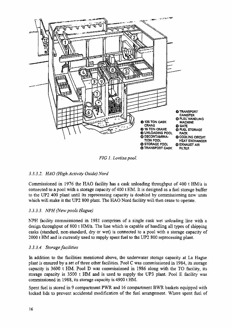
O 125 TON CASKCRANE
O 15 TON CRANEG UNLOADING POOLO DECONTAMINA-
TION POOL©STORAGE POOL©TRANSPORT CASK
OTRANSPORTCANISTER
O FUEL'HANDLINGMACHINE
OGATE© FUEL STORAGE
RACKQ COOLING CIRCUIT
HEAT EXCHANGERO EXHAUST AIR
FILTER
FIG 1. Loviisa pool.
3.3.3.2. HAO (High Activity Oxide) Nord
Commissioned in 1976 the HAO facility has a cask unloading throughput of 400 t HM/a isconnected to a pool with a storage capacity of 4001 HM. It is designed as a fuel storage bufferto the UP2 400 plant until its reprocessing capacity is doubled by commissioning new unitswhich will make it the UP2 800 plant. The HAO Nord facility will then cease to operate.
3.3.3.3. NPH (New pools Hague)
NPH facility commissioned in 1981 comprises of a single cask wet unloading line with adesign throughput of 800 t HM/a. The line which is capable of handling all types of shippingcasks (standard, non-standard, dry or wet) is connected to a pool with a storage capacity of2000 t HM and is currently used to supply spent fuel to the UP2 800 reprocessing plant.
3.3.3.4. Storage facilities
In addition to the facilities mentioned above, the underwater storage capacity at La Hagueplant is ensured by a set of three other facilities. Pool C was commissioned in 1984, its storagecapacity is 3600 t HM. Pool D was commissioned in 1986 along with the TO facility, itsstorage capacity is 3500 t HM and is used to supply the UP3 plant. Pool E facility wascommissioned in 1988, its storage capacity is 49001 HM.Spent fuel is stored in 9 compartment PWR and 16 compartment BWR baskets equipped withlocked lids to prevent accidental modification of the fuel arrangement. Where spent fuel of
16

greater than 3.75% U235 initial enrichment is received the fuel bumup is measured using asystem "PYTHON" to allow storage at the same capacity.Pool temperature is maintained below 40°C and water activity below about
. T "3
5 x 1 0 Ci/m (18.5 MBq/m ) during normal operation.
One feature which differs from most APR pools are the deployment of in-pond heatexchanger/ion exchange units (NYMPHEA) in pools C, D and E. This design has theadvantage of precluding the siting of radioactive portions of the cooling network outside thepool. Movement of fuel between pools is performed by conveyors between pools C, D, and E,and a dry transfer corridor between pool C and NPH.
3.3.4. Germany
Germany has limited APR wet storage facilities located at Greifswald NPP.
The Greifswald power plant now shut down consisted of five Russian WWER-440 units eachwith associated AR pools and a central APR pool of standard design for WWER plants. It issimilar in design and capacity to the APR pool at Kozloduy (see section on Bulgarian APRpools).
All pools are currently being cleared of fuel to allow decommissioning activities tocommence. Some of the fuel of low burnup was sent to the Paks power plant in Hungary (forre-irradiation), but the remainder is planned eventually to go into dry cask storage.
3.3.5. India
India has a single AFR(RS) facility located at Tarapur.
3.3.5.1. Tarapur
The 2801HM (2000 assemblies) Tarapur AFR(RS) facility, which was commissioned in 1991with a 25 year design life, was provided to service the two Tarapur BWR reactors whilst theback-end policy was derived. The facility now also accommodates fuel from the RajasthanPHWR NPP (Kota) as an interim measure whilst additional storage facilities are beingprovided at that plant.
The seismically designed facility measures 73 m x 35.5 m x 22.3 m high and comprises ofspent fuel, services and waste management buildings. A more detailed description of thefacility is provided in Ref. [5].
Receipts into the facility are made in a storage cask, originally intended for dry storage atother locations, with a capacity for 37 fuel assemblies (5.2 t HM) and is normally loaded with10 year cooled fuel.
The pool is stainless steel lined, measures 9mx 1 3 m x 13m deep, is built partly belowground and has 1.5 m thick walls. Fuel is loaded into high density fuel racks of 12 x 12 arrayby using a 1 t bridge crane. Fuel racks are designed to meet both criticality and seismicrequirements.
17
Because the equilibrium temperature of the long cooled fuel has been calculated not to exceed60°C (when the facility is fully loaded) no emergency cooling system is provided. However, aheat exchanger has been provided to keep water temperature below 42°C under normaloperating conditions.
3.3.5.1.1. Operational experience
The facility has operated satisfactorily since it was commissioned in 1991. Visibility, pondwater activity and temperatures are all well within limits. Radiation levels over the ponds isalso well within limits.
3.3.6. Japan
Japan has three APR wet storage facilities, two AFR(OS) facilities at the reprocessing sites ofTokai Mura and Rokkasho Mura, and a new AFR(RS) located at the Fukushima Daiichi NPP.
3.3.6.1. Tokai Mura
This relatively small 100 t HM capacity AFR(OS) facility acts as a buffer for the Tokai Muraprototype 0.7 t HM/day capacity reprocessing plant. The facility comprises of casksreceipt/preparation areas, unloading pool, storage pool and intermediate pool for fuel feedingto the head end of the reprocessing plant. Fuel is stored in baskets.
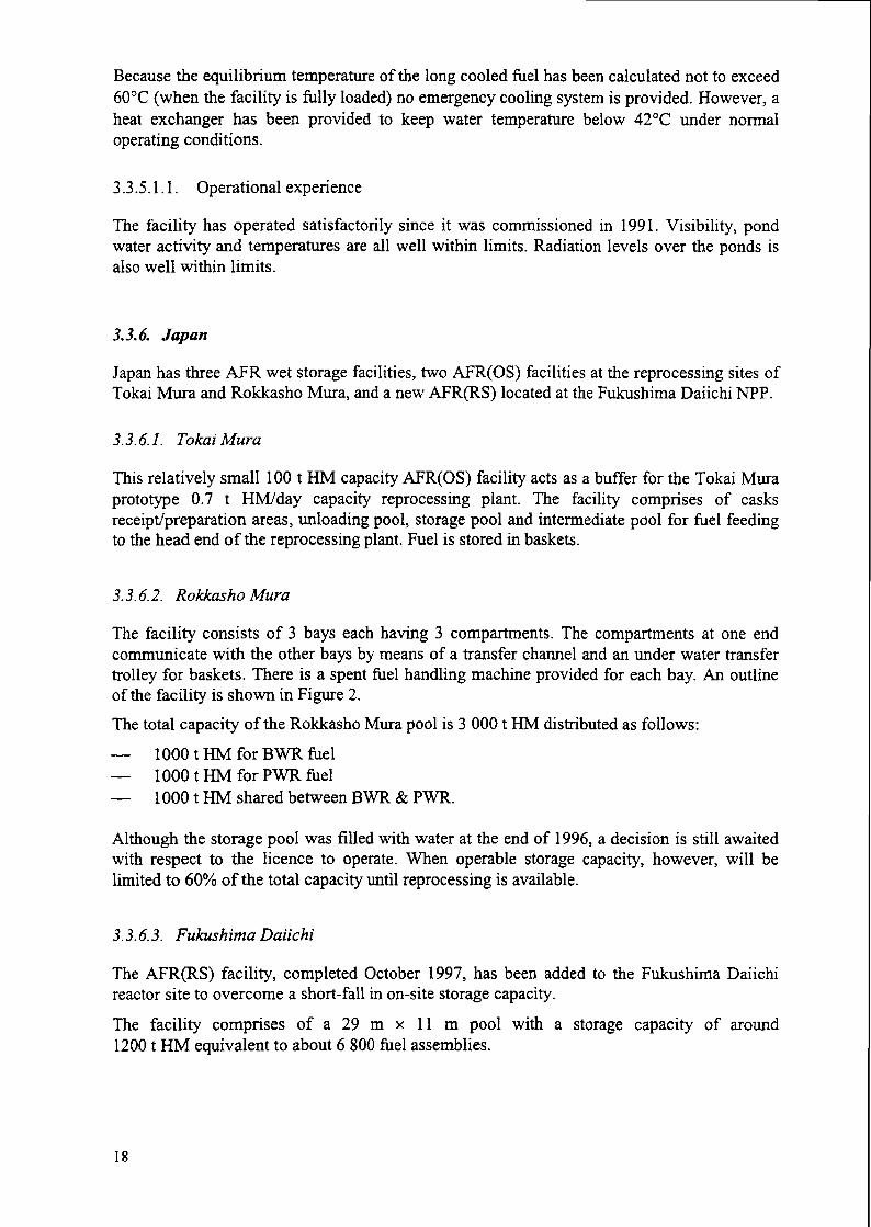
3.3.6.2. Rokkasho Mura
The facility consists of 3 bays each having 3 compartments. The compartments at one endcommunicate with the other bays by means of a transfer channel and an under water transfertrolley for baskets. There is a spent fuel handling machine provided for each bay. An outlineof the facility is shown in Figure 2.The total capacity of the Rokkasho Mura pool is 3 0001 HM distributed as follows:
— 1000 t HM for BWR fuel— 10001 HM for PWR fuel— 10001 HM shared between BWR & PWR.
Although the storage pool was filled with water at the end of 1996, a decision is still awaitedwith respect to the licence to operate. When operable storage capacity, however, will belimited to 60% of the total capacity until reprocessing is available.
3.3.6.3. Fukushima Daiichi
The AFR(RS) facility, completed October 1997, has been added to the Fukushima Daiichireactor site to overcome a short-fall in on-site storage capacity.
The facility comprises of a 29 m x 11 m pool with a storage capacity of around12001 HM equivalent to about 6 800 fuel assemblies.
18

FIG. 2. Storage pool at Rokkasho reprocessing plant.
3.3.7. Russian Federation
The Russian Federation has 6 AFR facilities as detailed in Table V The development/designcriteria for Russian APR facilities is given in detail in Annex B of Ref. [6].Twenty years operational experience of spent fuel storage m water pools has demonstratedhigh corrosion resistance of intact fuel during long term storage In addition, no seriousdeterioration of defective fuel occurred after several years of storage m water pools. Wetstorage m The Russian Federation is proven technology. However, continued improvement ofwet storage technology is sought through the continued study of the behaviour of spent fuelduring long-term storage (damaged fuel m particular) and through rerackmg m the storagepools in the operating plant.Following are typical examples of Russian RMBK and WWER AFR facilities.
3.3.7.1. Leningrad
Located at the Leningrad NPP site the AFR (RS) storage facility was designed to hold 2000 tHM of RMBK spent fuel. The storage area consists of five water pools (one is a reserve)designed for storing spent fuel in cans, each pool can accommodate up to 4380 cans. Thecapacity of each can is one spent fuel assembly.RMBK spent fuel storage differs from the norm in that individual fuel assemblies are sealedinto cans which are stored suspended just above the pool floor m a fixed slot, at a spacing of110 x 230 mm, in a metal beam placed across the pool This design of storage provides afixed storage layout to ensure sub cnticahty is maintained The beams also provide the
19
necessary support for the pool lids to minimise water evaporation, and operator access formanual fuel placement operations.
TABLE V. APR STORAGE FACILITIES IN THE RUSSIAN FEDERATION
Location of the facility
Leningrad NPP
SmolenskayaNPPKurskayaNPPNovo-Voronezh NPPKrasnoyarsk Mining andChemical PlantAssociation Mayak
Fuel stored Design capacity Current(t HM) inventory
(tHM)RBMK-1000a
RBMK-1000RBMK-1000WWER-1000b
WWER-1000
WWER-440BN-600
2000
20002000400
6000
560
2500 (with thestand-by bay)
4001700
112000
435
Operating period
1984 to present
1996 to present1986 to present1986 to present1984 to present
1975 to present
1 Burnup 25 MS d/t HM; 2.4% enrichment; maximum cladding temperature 50°C; 3 years ageing priorto storage.
b Burnup 50 MW d/t HM; 4.4% enrichment; maximum cladding temperature 50oC; 3 years ageing priorto storage.
A typical fuel receipt involves a loaded TK-8 cask which after preparation has been placedinto the unloading pool. The transport basket with 9 fuel assemblies is then removed from thecask and set on a intermediate shelf in the unloading pool. These operations are performed byusing a 15 t cable trolley with a 5 t capstan and are remotely controlled from the operators'room.A 20/5 t bridge crane transfers the transport basket to the deep section of the unloading poolwhere individual fuel assemblies are removed and placed in cans. The loaded can istransferred to the main pool hall where it is initially parked at the end of a channel where thepool cover has been removedFuel handling/placement in storage is performed by a 1 t-hoist which is height limited andcontrolled from the pool hall deck. Once the loaded cans have been suspended on the beamsof the metal deck of the pool hall the opened portion in the deck is covered again to preventwater evaporation.3.3.7.2. Operating Experience
The time required to transfer and place fuel into storage is approximately 12-18 hours. Thisincludes the return of the TK-8 container from the AFR(RS) to the reactor unit, loading TK-8with fuel, transport to the storage building and basket unloading from TK-8. About 8 hoursare required for all fuel unloading from the transport basket (with 9 fuel assemblies) into cansand placing the cans into storage. The collective dose for each fuel loading operation isapproximately 1.9 mSv (as was predicted). The collective dose during maintenance andoperation is no more than 50 p.Sv/a (a specified value). The pool water activity is very low at3.3 Bq/kg.
20
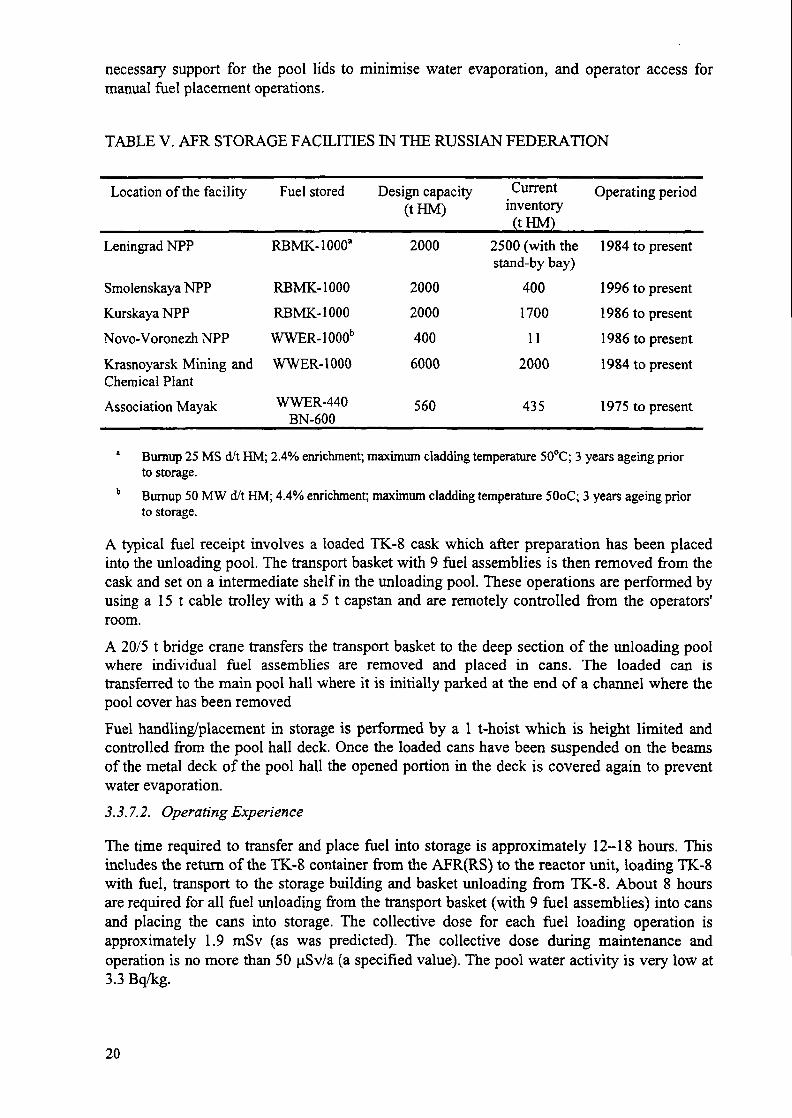
3.3,7.3. Krasnoyarsk APR (OS) storage facility
The storage facility is located at Krasnoyarsk RT-2 reprocessing plant site. The facility wasdesigned to hold up to 6000 t(U) of spent WWER-1000 nuclear fuel in baskets in readinessfor fuel reprocessing in the RT-2 reprocessing plant; yet to be commissioned (Fig. 3.).
Central storage facility at the mining and chemical plantReception areaStorage areaTransport hallReloading bayCask wagon reception sectionStorage bay160/32 t crane16 t crane
9. Special 16 t crane10. Reloading machine11. Cask wagon12. Cask13. Guard fence14. Yoke15. Hydraulic lock16. Storage basket
FIG. 3. RT-2 pool.
The facility comprises a reception, storage, and process engineering areas.Transport cask receipt is not more than two casks per day and can be either TK-10's orTK-13's of 6 or 12 assembly capacity.The storage pool consists of 15 bays, with one reserve bay. The bays are connected with oneanother and with the unloading pool via a transport corridor. Each section can be separated bya removable hydraulic lock and emptied independently for maintenance and repair. Basketswith fuel assemblies are placed on the pool floor. The pool is a rectangular shaped structuremeasuring 11 300 x 3450 x 8400 mm and lined with stainless steel. It is separated from thetransport hall by a metal deck with slots which are closed with flap covers. The slot openingsfacilitate the work of operating personnel and affords a fixed pitch for rows of baskets sincethe basket is carried on a rod by a 16-t crane along the open slot in the deck. The fixed pitch is1600 x 1600 x 1600 mm and, with a basket diameter of 1460 mm, prevents the possiblecollision of baskets. The pool can accommodate between 69 to 84 baskets, however, capacitycan be increased if the central transport channel is also filled up.
21

Pool water temperature is maintained at 40°C by an automatic water cooling system andactivity levels controlled by a water purification system which is usually operated once a weekper pool.
Operating experienceTime required for unloading a cask of spent fuel is 4 hrs. The time for the basket loading andplacing into storage is 12 hrs. Permissible occupational dose limit does not exceed thespecified value of 50 ^Sv/a.
3.3.7.4. Novo- Voronezh NPP
The AFR (RS) WWER-1000 facility is located at the Novo-Voronezh NPP site. The designcapacity is 400 t HM. Fuel assemblies are stored in racks at a space of 400 mm in a triangulararrangement under the shielding water.The storage bays are located in a row on either side of the cask reception room. Thedecontamination area accommodates a facility for cask decontamination and painting. Thecask reception room has a stepwise configuration with two locations. In the upper location thecask lid is removed and in the lower location the cask is unloaded. The storage bayscommunicate with each other through openings with sluice gates. The storage bays arerectangular ferro-concrete structures with dimensions of 6200 x 4400 x 16 400 mm withdouble lining and leakage collection from behind the liner.Fuel arrives by rail in TK-10 transport casks (capacity: 2.6 t HM or 6 WWER-1000 fuelassemblies) and CASTOR casks (capacity 5.2 t HM or 12 WWER-1000 fuel assemblies).Transport operations with casks are performed by a 160/32 t crane in the main hall. Caskloading/unloading operations are performed by a special fuel handling machine. The facility isin operation for loading/unloading operations 24 hours per day for 20 days per year.The facility is equipped with cladding leak testing and gamma scanning for bumupdetermination.
— The cooling system is brought into operation when the pool water temperature rises to45-50°C. The cleaning system operates periodically; on average 24 hours/week/bay.
— The water quality is controlled to the following specifications:— pH-no more than 4.3;— HsBOs concentration - no more than 13 g/kg;— Cl - ion content - no more than 150 mg/kg;— NHU - content - no more than 50 mg/kg;— The water activity is controlled and does not exceed 10 Bq/kg.
The AFR (OS) storage facility at Mayak
The interim AFR(OS) wet storage facility is located at the site of the Mayak ReprocessingPlant. This facility reprocesses WWER-440 and research reactor (submarine) fuel.The facility comprises a reception, storage, and process engineering areas. Fuel is stored inbaskets. A cross-section of the reception area is shown in Fig. 4.
22

Crane Q=l5l L=9m ^Crane Q=15t L=25m
v>Camsler basket
FIG. 4. Mayak reception pool.
3.3.8. Slovakia
The interim AFR(RS) wet storage facility in Slovakia is located at the site of the JaslovskeBohunice NPP.
3.3.8.1. Bohunice
In 1983 construction started on an interim AFR(RS) storage pool at Bohunice NPP and it wascommissioned in 1987. The design capacity of the facility is 6001HM (5000 fuel assemblies).It is expected that the storage will be completely full by the end of 1998.
The facility consists of three working bays and one reserve bay all interconnected by a waterchannel. The structure including all the service areas occupies a space of about45 m x 66 m. The pools are located at ground level and there is a substantial sized receptionbay for transport containers. An overhead crane of 125/20 t capacity lifts the casks into anunloading well and the fuel is removed by a 15 t bridge crane into an assembly washing areabefore transferring to the storage bays.
The facility is of standard USSR WWER design (see Kozloduy, Bulgaria), and storesWWER-440 fuel only.
Operating experience
Although the design maximum water temperature is 50 °C, under normal operating conditionsobserved water temperatures have been in the 20-30 °C range. The facility only stores non-leakers. The fuel is stored in open baskets, 30 assemblies per basket. No abnormal
23
occurrences have been observed. The specified limits on water activity and temperature werenot exceeded. No water leakage has been observed.
Other relevant information
The official policy is not to commit any further fuel for reprocessing. Preparation is beingmade to extend the existing storage capacity (600 t HM) and to consider higher densityracking. This approach would replace the existing 30 fuel assembly baskets with basketscontaining approximately 50 assemblies. Analysis is being made of the pool floor pad loadingand the cooling capability for higher density racking. The additional space could extend thestorage capacity to 2005.
An alternative is to investigate the dry storage option in the event that the extended poolcapacity is not achieved. There will also be a need for storage capacity for the second NPP atMochovce which is expected to start up in 1998.
3.3.9. Sweden
Sweden has a single APR (OS) interim storage facility (CLAB) located on the Simpevarppeninsula near the Oskarshamn nuclear power plant. The facility differs from any other APRin that the storage pool is entirely located underground in rock to overcome safety issues suchas impact from aircraft.
CLAB
CLAB (first operation 1985) with a planned operational life of around 60 years comprises oneabove ground (site services, cask handling and fuel preparation operations) and oneunderground section (fuel storage). A detailed description of the facility including technicaldata and design criteria is given in Annex A of Ref. [6].The receipt building has three receiving pool lines, two of which are specially equipped forreceiving the TN17 Mk2 cask. The third pool which accommodates fuel leakage detectionequipment is primarily provided for receipt of casks other than TN17 Mk2. The receipt poolsare arranged so that cask immersion is into non-contaminated water prior to fuel transferoperations into high density fuel canisters; capacity 25 BWR or 9 PWR fuel assemblies.The conversion to higher density fuel canisters has increased the total storage capacity for thefacility from 30001 HM (as given in Reference 6) to 50001 HM.Transfer of individual storage canisters to the underground storage complex is by a fuelelevator containing a water filled cage; the whole process being controlled remotely. Onpassing from the pools of the receiving section to the elevator shaft, the elevator cage goesthrough a water trap. The elevator shaft itself is not water-filled.The storage complex is in a rock cavern 25-30 metres below the surface. It is 120 metreslong, 21 metres wide and 27 metres high. It contains four storage pools and one smallercentral pool connected to a transport channel. Each storage pool can hold up to 1250 t HM ofspent nuclear fuel, giving a total storage capacity for the facility of 50001 HM.The storage pools have very thick concrete walls with extremely strong reinforcement. Loss ofwater from the pools can only occur by evaporation in case of total loss of electricity supply
24
and cooling. The pool water will heat up to close to 100°C. in about one week. If no feedwateris supplied, the water level will drop to the top at the fuel after about one month.The fuel transport cask cooling system, where the greatest accumulation of radioactivity couldbe expected, has been equipped with a comprehensive system permitting remote removal ofcomponents by means of shielded casks.In order to reduce the impact of possible airborne contamination in the receiving hall, thenormal air change rate is as high as five times per hour in the floor zone where the operatorswork. If necessary, this air exchange rate can be extended to the total volume of the receivinghall by use of an extra ventilation system.
Operational experience
To August 1997 CLAB had received approximately 900 transport casks, 840 containing fueland the remainder highly active core components (control rods etc.). The fuel inventorycorresponds to around 2 700 t HM comprised of:
— BWR fuel assemblies— PWR fuel assemblies— MOX fuel assemblies— Agesta fuel assemblies (PHWR)— Canisters with fuel debris.
Part of the fuel assemblies have been reloaded from the original storage canisters to the newhigh density storage canister.Uncertainties such as crud release during dry cask cooling operations have been found to be50-100 times less than was assumed in the Final Safety Analysis Report (FSAR). This factmay to a great extent be attributed to the good water chemistry in the Swedish reactors and thecorrosion resistant material in the turbine and feedwater systems resulting in relatively smallquantities of crud.During the first month of operation problems with the slot filter and backwash filter arose. Bydeveloping a new backwash filter and changing the slot filter to a sintered metal filter theproblem was resolved.A surprising fact is that the activity release to the storage pool water is more than 95% ionic.In the Final Safety Report, the opposite was assumed predicting 90% to be in paniculate form.The activity released is 90-95% 60Co, the remainder being mainly 54Mn. Less than 1% is137Caesium.The activity concentration at 2000 t HM is low, 7 MBq/m3, which however is higher thanexpected. The reason for this is the above mentioned high proportion of ionic release.Particles would have settled down on the pool bottom and would not have been observed inthe water samples taken from the pools. Instead the activity now remains in the water.The influence of pool water temperature on activity release rate was measured in 1988 byallowing the pool temperature to rise from 28°C to 36°C. The resultant effect was a 2.1 foldincrease in activity concentration.
3.3.9.1. Radiation doses
During the years 1986-1993, the collective dose to CLAB staff and contractors was between65 and 135 person mSv, which was about 25% of expected values in the FSAR. In the years
25
1993-1994, the yearly dose was 100-115 person mSv. The rising tendency can be explainedby a build-up of activity in plant systems, increased maintenance work and more staffmembers passing the dose detection limit. The development is closely watched and measuresare being taken and planned to break the tendency.
3.3.10. United Kingdom
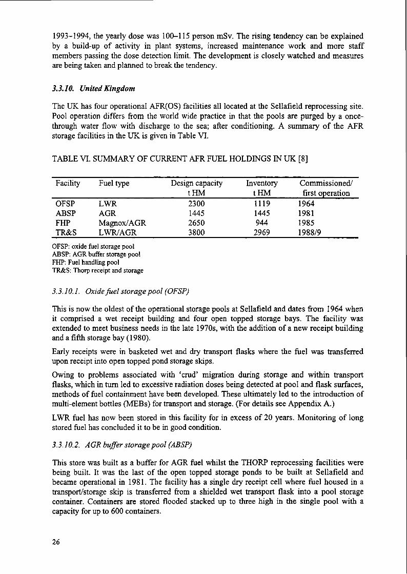
The UK has four operational AFR(OS) facilities all located at the Sellafield reprocessing site.Pool operation differs from the world wide practice in that the pools are purged by a once-through water flow with discharge to the sea; after conditioning. A summary of the APRstorage facilities in the UK is given in Table VI.
TABLE VI. SUMMARY OF CURRENT APR FUEL HOLDINGS IN UK [8]
Facility
OFSPABSPFHPTR&S
Fuel type
LWRAGRMagnox/AGRLWR/AGR
Design capacitytHM2300144526503800
InventorytHM11191445944
2969
Commissioned/first operation
1964198119851988/9
OFSP: oxide fuel storage poolABSP: AGR buffer storage poolFHP: Fuel handling poolTR&S: Thorp receipt and storage
3.3.10.1. Oxide fuel storage pool (OFSP)
This is now the oldest of the operational storage pools at Sellafield and dates from 1964 whenit comprised a wet receipt building and four open topped storage bays. The facility wasextended to meet business needs in the late 1970s, with the addition of a new receipt buildingand a fifth storage bay (1980).Early receipts were in basketed wet and dry transport flasks where the fuel was transferredupon receipt into open topped pond storage skips.Owing to problems associated with 'crud' migration during storage and within transportflasks, which in turn led to excessive radiation doses being detected at pool and flask surfaces,methods of fuel containment have been developed. These ultimately led to the introduction ofmulti-element bottles (MEBs) for transport and storage. (For details see Appendix A.)LWR fuel has now been stored in this facility for in excess of 20 years. Monitoring of longstored fuel has concluded it to be in good condition.
3.3.10.2. AGR bujfer storage pool (ABSP)
This store was built as a buffer for AGR fuel whilst the THORP reprocessing facilities werebeing built. It was the last of the open topped storage ponds to be built at Sellafield andbecame operational in 1981. The facility has a single dry receipt cell where fuel housed in atransport/storage skip is transferred from a shielded wet transport flask into a pool storagecontainer. Containers are stored flooded stacked up to three high in the single pool with acapacity for up to 600 containers.
26
Major operational changes since commissioning of this pond have been the receipt ofdismantled fuel, increasing storage capacity from 500 t HM to around 1500 t HM, and theintroduction of the fuel cladding corrosion inhibitor sodium hydroxide by dosing the poolwater to pHll.5. The susceptibility of AGR fuel to cladding corrosion has been reported aspart of the Co-ordinated Research Programme on Behaviour of spent fuel during long-termstorage (BEFAST) [7].Since the introduction of corrosion inhibitors and stringent control of water chemistry, nofurther pin perforations have been discovered over a thirteen year period.
3.3.10.3. Fuel handling plant (FHP)
Commissioned in 1985, the facility comprises three dry receipt caves, three main storageponds for the storage of Magnox and AGR fuels, three sub ponds, decanning cells for Magnoxfuel and AGR dismantling lines. All ponds and sub ponds are interconnected in a building 150metres long by 25 metres wide raised above ground level.Fuel receipt and storage is similar to the ABSP, the main differences are that the pool storagecontainers are predosed in the receipt cell to (pH13, (Cl" + SO4
2" ) < 0.5ppm). AGR fuel isreceived from reactor stations in fifteen element fuel skips. Magnox containers are sealed andullaged with nitrogen gas prior to storage to minimise the release of activity and claddingcorrosion products to the bulk pond water.Pool water within the facility is predosed to pHl 1.4 and cooled to 15 °C by refrigeration unitsto minimise activity leach rates.Magnox fuel is stored for up to 18 months. Prior to reprocessing, Magnox containers aretransferred to a sub pond containing a skip washer. Here, the container is purged to removesoluble activity, and tumble washed to remove cladding corrosion products. Effluents fromthese processes are directed to the Site Ion Exchange Effluent Plant (SDCEP). The fuel is thendecanned (cladding removed) before cask transfer to the Magnox Reprocessing Plant.Unlike Magnox receipts, AGR containers are stored flooded for up to 180 days to allow forheat decay to meet the fuel dismantler heat loading limits. A 3:1 fuel consolidation is achievedby dismantling, the rods being placed into 285 mm diameter by 1 metre stainless steel slottedcans. (A more detailed description of the rod consolidation process at BNFL is given inAppendix B.) The cans are transferred into twenty compartment skips and either returned tostorage in FHP, transferred to the ABSP or transferred directly to THORP receipt and storagefor reprocessing.
3.3.10.4. THORP receipt and storage (TR&S)
Commissioned in 1988, THORP Receipt and Storage (TR&S) is the latest APR to be built atSellafield. Constructed to the latest international building standards the design of the facility isbased around BNFL's practice of fuel containerisation for both transport and storage.TR&S is primarily used for the receipt and intermediate storage of LWR fuel prior toreprocessing, but it is also used to store a reprocessing buffer, up to 166 containers, of AGRfuel. The facility comprises two main buildings, the receipt building and the pond hallbuilding. The two buildings are interconnected by an access channel, and since 1995 the PondHall Building has been connected to THORP Feed Pond, by a further access channel, wherethe fuel is taken for reprocessing after a minimum cooling period of 5 years (for LWR fuel).
27
The receipt building stands some 36 m high with an operating floor at the 11 m level. Newreceipts of LWR fuel are brought into the facility by rail at the base of the building and liftedto the operating floor through one of two hoist wells using a 1501 crane.Flask preparation is undertaken in one of three preparation bays and flask decontamination inone of a further three decontamination bays. Provision is made to undertake all flaskpreparation operations automatically, this is routinely practised for venting and flushingoperations, whilst automatic unbolting is now only likely to be used for high burnup fuelreceipts. All decontamination operations are manual, although there are facilities for auto caskwashing.The inlet pool is on two levels and has a deep section of 14.6 m for the removal of LWR fuelMEBs and a shallower section of 9 m depth for the removal of the much shorter AGR fuelskips. For in-pond operations, the inlet pond is serviced by the inlet pond handler (effectivelya travelling bridge with a heavy duty tooled hoist for the movement of fuel-baring containers)which is controlled remotely from a shielded console located at the side of the inlet pond inthe clean area. The inlet pond can also be isolated from the main pond by an electricallyoperated sluice gate which forms a water tight seal allowing inlet pond draining formaintenance and decontamination.
The Pool Hall Building stands 35 m high with an operating floor at the 10 m level. The hallcomprises two enclosed interconnecting 72 m long by 36 m wide by 9 m deep reinforcedconcrete pools. The pools, built above ground, are multi skinned with leak detectionequipment located at the interspace/drainage channel of the two skins and stainless steel cladat the water line.Two storage systems are in operation: multi-element bottles (MEBs) stored in pairs in a rackfor the storage of LWR fuel, and AGR containers stacked up to three high for the storage ofAGR fuel.The two pools are serviced by a main pool handler (MPH) for movements within the pools, arack transfer machine (RTM) for movements between buildings, and recirculating coolingwater system to maintain pond water temperature below 30°C. Both the MPH and RTM areremotely controlled from the receipt building operational control room.Since 1988 TR&S has processed some 3650 t HM of fuel without a single incident. Doseuptake to operators has been maintained well below 1 mSv/a c.f. the design criteria for thefacility of 5 mSv/a. The effectiveness of containerising fuel is supported by the very low poolwater activity levels being maintained at around 4 MBq/m3
3.3.11. Ukraine
Ukraine has one wet AFR facility located at the Chernobyl NPP site. The design and storagetechnology of this facility is the standard for AFRs used for storing spent fuel from RMBK -1000 reactors. A description can be obtained from the section on the Leningrad NPP in theRussian section above.
3.3.12. USA
The USA has a single wet AFR(OS) facility located at Morris [1].
28
3.3.12.1. Morris
Operational since 1972 the Morris AFR(OS) facility consists of cask receiving area,decontamination area, cask unloading pool, fuel storage pools 1 and 2, low level radioactivewaste evaporator, control room, and pool water cleanup and cooling system.The facility was designed to receive one year cooled spent UO2 nuclear fuel up to 5% 235U andmaximum burnup of 44 GW d/t HM from PWRs and BWRs. By 1976, the fuel storagecapacity of the facility was increased from 100 t HM to 7501 HM by the installation of higherdensity fuel storage racks and through changes in fuel handling and support systems.On receipt a 125 ton crane lifts the cask from the trailer or rail car and sets it upright on thedecontamination area pad. The interior of the cask is flushed with pool water, which is thensampled and analysed for radioactive contamination as a means of detecting defective fuel. Ifdefective fuel is suspected, special procedures are employed for opening and unloading thecask.Fuel is unloaded from the cask submerged in the unloading pool using a 5 ton fuel handlingcrane. The unloading and storage pools are served by the pool crane — a manual controlbridge crane of 7.5 ton capacity. The pool crane has a platform on the north side of the bridgethat provides a work station for the fuel handling operator. An underwater closed-circuittelevision system is available to support fuel handling operations.
3.3.12.1.1. Operating experience
There has been no significant fuel leakage (as determined by measurement of pool wateractivity), indicating that the fuel is a stable, inert material while in the storage poolenvironment. Effective control of water quality, radioactive material concentration in thewater, cask contamination, and airborne radioactive material has been demonstrated.
4. EXPERIENCE WITH DRY STORAGE OF SPENT FUEL
4.1. Introduction
This section provides a survey of dry spent fuel storage facilities including those in operationand those being licensed and built. The number and types of dry storage facilities in operationand under construction has significantly increased during the past ten years. In addition to thebasic storage only technologies (vaults, casks, and silos), some cask and silo technologies arealso being used or developed for dual-purpose (storage and transport) or multi-purpose(storage, transport and disposal) applications. Dry storage facilities generally remove decayheat by passive cooling and have low operating costs. They also provides the advantage ofincremental storage capacity expansion by allowing additional storage capacity to beconstructed on an as-needed basis. The majority of dry storage facilities have been constructedat reactor sites. For purposes of this report, these facilities are classified as AFR (RS)facilities. Facilities at Surry, H.B. Robinson, Fort St. Vrain, Pickering, and Gentilly 2 areexamples of AFR (RS) facilities. In addition, several AFR dry storage facilities have beencommissioned that are AFR (OS) facilities, e.g. Gorleben, Ahaus.Container systems, which include casks and silos, comprise the majority of the dry storagetechnologies in use. Descriptions of commonly used container systems are provided inAppendix C.
29

Spent nuclear fuel has been handled and stored for short periods under dry conditions sincethe 1940s. The use of continuous dry storage of spent fuel began in the early 1960s. In the late1970s, several countries concluded that there are advantages to storing spent fuel under dryconditions and started development programmes, which have culminated in the operation oflicensed dry storage facilities in several countries.The storage of zirconium alloy clad spent LWR fuel in an inert gas atmosphere is a proventechnology up to temperatures of about 450°C. Dry storage of that fuel is licensed in Germanyfor temperatures <410°C and in the USA for temperatures <380 °C in an inert atmosphere.Dry storage of spent CANDU fuel in air at temperatures up to 160°C has been licensed inCanada. Dry storage of Magnox type fuel has been licensed in the United Kingdom in air orinert atmosphere. Degradation of fuel during dry storage is unlikely and no significant fueldegradation in storage has been observed. Tables summarising dry storage experience for eachdry storage type are provided in this section.
4.2. Vault facilities
Vault facilities have been constructed in Canada, France, Hungary, the United Kingdom andthe USA using a variety of vault dry storage technologies. Table VII summarises internationalexperience with dry storage in vault facilities.
4.2.1. Canada
Hydro Quebec's Interim Spent Fuel Dry Storage (ISFDS) facility went into operation inSeptember 1995 after its first storage module was completed. It was licensed by AtomicEnergy Control Board (AECB) to store spent fuel from the operating 680 MW(e) Gentilly 2CANDU power reactor.This is the first application of the MACSTOR concept to store spent fuel from a CANDUreactor which evolved from AECL's (formerly Atomic Energy of Canada) silo basedtechnology. Its advantages are superior thermal performance, a more compact storage site, aswell as overall economical and operational benefits. One concrete module stores the samequantity of spent fuel as 22 stand alone silos (concrete canisters) used at Pt. Lepreau reactorsite.
TABLE VII. SUMMARY OF DRY STORAGE IN VAULT FACILITIES
Country/facility
CanadaGentilly 2
FranceCASCAD
HungaryPaks
UKWylfa
USAFort St. Vrain
Fuel type
CANDU
HWR
WWER-440
Magnox
HTGR
Design capacityt(HM)
3648
180
162
958
15.4
Current inventoryt(HM)
20
180
54
680
15.4
Operatingperiod
1995 to present
1990 to present
1997 to present
1971 to present
1991 to present
30
4.2.1.1. Facilities for dry spent fuel storage
The storage site, which is approximately 90 m wide and 200 m long, is located on-site in thevicinity of the spent fuel bay. It allows space for the construction of 15 additional storagemodules to take care of the lifetime spent fuel arisings of the station. The foundation for thestorage modules was prepared through continuous concrete pouring from the rock (6 m belowthe ground) up to the ground level.The service building around the spent fuel bay was modified and an extension was built toaccommodate the fuel handling facilities needed for dry storage. A two-transfer cask methodis used in conjunction with a new cask handling crane installed in the building extension. Thenew facilities are essentially the same as used for dry spent fuel storage by Gentilly 2's sisterCANDU reactors at Pt. Lepreau (Canada) and Wolsong 1 (Republic of Korea).
4.2.1.2. Fuel handling operations
Figure 5. depicts the fuel handling operations. The spent fuel bundles are first manuallyloaded underwater into storage baskets. The Shielded Work Station (SWS) is installed in theservice building extension adjacent to the storage bay. The chute, to guide and shield thestorage basket, is installed over the edge of the bay. The transfer cask positioned over thechute hoists the basket out of the bay. After the basket is drained, the cask is rolled out on railsto the SWS. The 30 ton crane positions the cask over the SWS and the basket is lowered,dried and seal welded thus forming the primary containment. The basket is then lifted into asecond transfer cask and brought to the storage site by the trailer. The 30 ton site crane liftsthe transfer cask atop the concrete storage monolith, called the CANSTOR module, where theloading platform guides it into position. The storage basket is then lowered into the storagecylinder. Once filled with 10 baskets, the shield plug is placed and seal welded to the top ofthe storage cylinder. Thus the secondary containment is established. Monitoring of the airspace in the storage cylinder allows for verification of the leak tightness of both containmentboundaries.A rail mounted gantry crane of 30 ton capacity is installed. It has a span of 30 m and iscapable of reaching any of the 20 storage cavities in the storage module.
4.2.1.3. CANSTOR module description
The CANSTOR module is a monolith, built outdoors using regular reinforced concrete, andcontains 20 storage cavities. Each cavity is fitted with a storage cylinder which is sealed afterloading of 10 storage baskets. Each basket contains 60 standard CANDU fuel bundles with102 mm diameter and 495 mm length. The module's labyrinth arrangement for air passageallows for heat removal by natural convection (see Table VIII).In spite of the excellent heat rejection capability of the CANSTOR module, the AECBrequested that the cladding temperature of the stored fuel be verified. To this effect, themodule was instrumented to allow for measuring and recording internal concrete and storagecylinder surface temperatures. It is expected that the interpretation of the results wouldindicate that there is a wide margin between the maximum allowable and derived fuelcladding temperature. Therefore spent fuel with a shorter cooling period than 7 years will bepermitted to be stored in subsequently built modules.
31

TABLE Vm. CANSTOR DESIGN PARAMETERS
Module height 8.1m
Module width 7.5 m
Module length 21.6 m
Storage capacity of module 228 t HM (12 000 bundles)
Storage cylinder material carbon steel
Storage basket material stainless steel
Fuel operating temperature <150 °C
4.2.2. France
CASCAD (CASemate CADarache), located on the Cadarache site, is intended for the drystorage of exotic fuels which cannot be economically reprocessed because of their specialproperties. This facility , which has been operated since 1990, is planned for a storage periodof 50 years, after which the fuel will be rehandled, according to the final decision about itsfate.Fuels to be stored arise from the CEA (Comissariat a 1'energie atomique) research reactorsand in particular from the Brennilis EL4 heavy water reactor.The major operating and safety principles include: (1) spent fuel canisterization and heliumpressurisation in order to maintain the containment barrier in case of fuel claddingdeterioration, and (2) spent fuel cooling with a passive convection system. It has to be notedthat for the EL4 fuel, the canistering operation is performed at the Brennilis reactor site.
4.2.2.1. Facility description
The CASCAD vault facility consists of a shipping cask receiving zone and a storage area.The facility is mainly composed of:
(1) A storage vault enclosing 319 storage wells. The main components of the storage wellsare :
— A leaktight cover, located in the upper section of the well, equipped with a system forsampling the internal atmosphere of the well;
— A biological shielding plug;— The walls of the well which constitute a containment barrier; and— A guide tube at the bottom of the well.
(2) A handling cell which enables the transfer of fuel from the transport cask to the well.The shielded slab ensures the support of the wells as well as the biological shielding ofthe operating team.
(3) Equipment rooms which enable the reception and preparation of the casks and containall the facility's equipment (control, ventilation, electricity).
32

Transfer Flask
CANSTOR™ Modules
Storage of a Fuel Basket in a CANSTOR™Module at the Storage Site
Transfer Flasks {,+tf
Shielded Work Station
„. Transfer Rask
Fuel Basket Transfer To Storage Site
Serai-Automated
Basket Welding
Fuel Drying and Basket Sealingin Shielded Work Station
Transfer Flask on Trolley
2
Fuel Assembly Filled Fuel BasketWork Table at Bottom of Pool
1- Kiel Assembly LoadingIaoaS.S. Fuel Basket
2- Rid Basket Loadingin Transfer Flask
FIG. 5. Fuel handling at Gentilly 2.
33

4.2.2.1.1. Storage vault
The storage vault consists of a concrete structure which provides biological shielding for bothhandling operations and storage. The lower part of the structure contains an array of storagetubes into the canisters are placed. The storage tubes are cooled by air circulation achieved bynatural convection. Cooling air is introduced through the lower part, then heated as it passesthe storage tubes. The heated air is released through a stack. The EL4 Canister externaldimensions: 0 = 104 mm H = 1100 mm
Two operators are required to perform unloading and storage operations. The individual doserate for the entire staff ranges between 0.35 mSv/a and 5.25 mSv/a. The dose rate measuredoutside the building is less than 10~5 mSv/a.
4.2.3. Hungary
In order to ensure the continuous operation of the Paks NPP, an interim spent fuel storagesystem has been chosen and licensed, and the construction of the storage building hascommenced. During the years 1991 and 1992 following an evaluation of the different spentfuel storage systems, the GEC ALSTHOM ESL Modular Vault Dry Store (MVDS) Systemhas been selected.
The licensing process took place during the years 1993 and 1994. The Construction Licensehas already been issued for construction of the first three phases (11 Vault modules; 4950assemblies). The operation of the Phase 1 is (3 Vaults, 900 assemblies) has started in late1997. A pictorial representation of the MVDS is shown in Fig. 6.
4.23.1. General description of installation
The vault module is a reinforced concrete structure which is covered by a structural steelbuilding to form a charge hall. The buoyancy driven air cooling flow inlet and outlet ducts arean integral part of the vault modules.The transfer cask reception building is a separate facility adjacent to the vault module. Ithouses the equipment necessary to handle and position the transfer cask prior to fuel assemblyremoval/drying operations. The transfer cask reception building also houses service and plantrooms, ventilation systems and provides health physics facilities for operating staff andmonitoring equipment.
Arrangement of major structures and equipment
The MVDS provides for vertical dry storage of irradiated fuel assemblies in a concrete vaultmodule. The principal components are a concrete and structural steel vault module housing anarray of steel fuel storage tubes each with a removable steel shield plug. Each fuel storagetube houses a single fuel assembly. A fuel handling machine moves the fuel assembly from awater filled transfer cask to the fuel storage tube via a drying tube. The fuel handling machineoperates in an enclosed volume above the fuel storage tubes referred to as the charge hall. Topermit the transfer cask to be prepared for fuel assembly removal by the fuel handlingmachine, the storage facility is provided with a transfer cask reception building. Theequipment required to load and transfer the fuel assemblies at the nuclear power plant ispresently licensed for use and is outside the design scope of the MVDS.
34

FIG. 6. Paks MVDS.
Safety features
The principal safety features of the MVDS are as follows:(1) Confinement provided by the fuel storage tube and gas services system;(2) The use of a nitrogen cover gas within the fuel storage tube providing a non oxidising
environment for the fuel assembly; and(3) A temperature level sufficiently low to prevent degradation and gross rupture of the fuel
cladding.
The principal design features that characterise the MVDS are similar to the buffer dry stores atWylfa described elsewhere (Appendix B of Ref. [2]).
Monitoring and surveillance
The condition of the fuel assemblies over long periods in storage can be monitored in theMVDS system. The MVDS provides opportunity to monitor visually the condition ofindividual fuel assemblies during storage. This can be achieved by raising the fuel assembliesinto the fuel handling machine and using TV systems. The ability to monitor the fuelcondition is an inherent part of the waste management function. Not only may the visualcondition of the fuel assembly have to be checked, but also the storage environment. Themethod of loading the fuel assemblies into the MVDS provides opportunity to check thecondition of the fuel assembly as received and to remove them for periodic inspection [2].
35

4.2.4. United Kingdom
The Wylfa Power Station has two types of dry storage facilities in commercial operation.Operated by Nuclear Electric pic, Wylfa reactor site comprises two 550 MW Magnoxreactors, three 86 t(U) carbon dioxide cooled short duration dry stores (DSC 1-3), and two350 t(U) air cooled buffer dry stores (DSC 4 and 5).
4.2.4.1. Short duration dry stores
The primary dry store cells were licensed for operation in December 1970 and the firstirradiated fuel loaded in March 1971. The first air cooled dry store was licensed for operationin September 1979 when the first spent fuel element was loaded. The store was full (28 922elements, approximately 350 t HM) by September 1981. The second air cooled dry store waslicensed for operation in May 1982 and is used for storage as and when required.Fuel to be buffer stored is pre-cooled in one of the three carbon dioxide cooled dry stores untildecay heat, determined by gamma monitoring, is found to be less than 60 watts ortemperatures fall to 150°C. Up to 64 assemblies are transferred at a time to one of the twobuffer stores which are kept at slightly below atmospheric pressure to ensure any leaks areinward. The stores are designed so that relative humidity is maintained below 50% by drierunits, ambient temperature is maintained by heat exchangers, and exhaust gases aredischarged to the atmosphere via a series of absolute filters.Each cell contains 588 steel tubes arranged concentrically in eleven rings. The tubes areapproximately 15 m long and each can hold 12 elements loaded on top of one another. Thetubes contain CC>2 at a pressure of 1200 mbar, the purity being maintained at better than 0.1%air concentration. Station operating procedures ensure that maintenance work which couldaffect the purity is not started until a specified time has elapsed from the loading of the lastfuel element. No forced cooling means are provided, the tubes being cooled by a flow of air inan open cycle system. The heat output of an element going into storage is 1 kW, with acladding temperature of 365°C.
4.2.4.2. Buffer dry stores
The second type of storage facility is a closed cycle air cooled dry store with two vaults. Eachis a reinforced concrete chamber about 60 m long, 11 m wide and 4.5 m high, with 2 m thickshield walls. The chamber contains 150 skips, 6 row with 25 skips in each row, plus 1 spareskip required for moving the skips about the storage area. Each skip consists of 16 rows of 12element tubes, making 192 in all. The skips are located on conveyor chains for longitudinaland transverse movement within the store. Cooling air passes through the bottom of the skipand around the outside of the tubes. The fuel in each skip draws cooling air according to itsneeds. The higher the heat output from the fuel, the greater the buoyancy head and hence thegreater the cooling flow. The bulk heated air is removed by a conventional fan and heatexchanger system. The air atmosphere in the store is subatmospheric (12 to 25 mbardepression) so that any leakage is always inward and not outwards from the store. The storageskips are chain driven to the fuel transfer machine via locating rails for loading.Generally, operational experience of the five dry stores has been very good. The notableexception is the widely reported water ingress into DSC4 due to a roofing fault. Discovered in1990, 45 fuel elements have suffered some degree of cladding corrosion as a result of watergetting into the store. The leakage highlighted inadequacies in the degree of humidity and
36

activity monitoring equipment. This has now been addressed by the provision of additionalequipment.
4.2.5. USA
Public Service Company of Colorado was granted an independent spent fuel storageinstallation (1SFSI) license by the US Nuclear Regulatory Commission (NRC) for the shutdown Fort St. Vrain high-temperature gas-cooled reactor (HTGR) in November 1991 usingthe modular vault dry store (MVDS) system designed by FW Energy, based on the GEC-Alsthom design. A total of 1464 HTGR spent fuel assemblies (15.4 t HM) are stored in theMVDS. The twenty year license authorises storage in the ISFSI of up to 1482 spent fuelelements, 37 reflector control rod elements, and 6 neutron source elements.Fort St. Vrain spent fuel elements are graphite elements in hexagonal arrays with a 36.0 cmmaximum cross section and 79.3 cm in length. The fuel characteristics for the ISFSI designincluded 600 day cooled, highly enriched uranium/thorium carbide fuel, maximum heat outputof 150 watts per assembly and an average heat output of 85 watts per assembly.The MVDS consists of a six concrete vault modules, two standby and one neutron sourcestorage wells, and a transfer cask reception bay. Each vault module consists of a matrix of 45storage positions. Each storage position holds 6 fuel elements or 12 reflector elements in afuel storage container (FSC). The loaded FSC is brought to the MVDS in a transfer cask (TC)from the reactor building and is received in the transfer cask reception bay (TCRB). The TC islifted from the TC trailer by the MVDS crane, and positioned vertically in the caskload/unload port. The FSC is then removed by the container handling machine (CHM) andmoved by crane over the charge face structure of the storage vault. When the CHM reaches itsposition, the crane lowers the CHM to the CFS in the vault module.
4.2.5.1. Civil structure
The MVDS civil structure consists of vault modules, the transfer cask reception bay, thecharge face structures, foundation structure, and standby and neutron source storage wells.The foundation for the vault modules is a reinforced concrete slab which extendsapproximately 3 m (10 ft.) beyond each side of the storage facility. Each vault module isshielded by a 1.07 m concrete wall.Ambient air flows into the vault modules through an inlet duct and passes around the outsideof the FSCs. The air exits through a reinforced concrete exhaust stack, which projects abovethe MVDS and is covered by a steel canopy. The charge face structure forms a roof over thevault modules and is made of carbon steel and filled with non-structural concrete for shieldingpurposes. The air outlet stack forms one wall of the charge hall and the other three sides aremade of reinforced concrete up to 10 m above ground level. The remainder of the walls andthe roof are made of steel sheathing supported by steel framework. The transfer cask receptionbay is part of the MVDS civil structure. It allows the transfer cask to be moved laterally by theMVDS crane into the cask load/unload port through an opening above the bay at the FSClevel.
4.2.5.2. Transfer cask reception bay
The TCRB provides an opening at the charge face level through which the TC can be liftedand moved laterally by the MVDS crane and seated on the cask load/unload port. The caskload/unload port consists of a seating ring and adapter plate with a shield ring to provide a
37
place for the transfer cask to be secured for unloading the FSC. The flanged top of the TCrests in a recessed seating ring so that the MVDS crane may position an adapter plate, shieldring, and isolation valve.
4.2.5.3. Fuel storage containers
The FSC consists of a cylindrical carbon steel tube body with an exterior aluminium spraycoating, double metal O ring seals, and a bolted lid. The FSC can hold 6 fuel elements or 12reflector elements. It is supported axially by a support stool fixed to the floor of the vaultmodule at its lower end. The top of the FSC is shielded by a depleted uranium shield plugduring transport, and by a shied plug placed above the FSC in the FSC during storage. TheFSC provides secondary confinement for irradiated fuel, the first confinement barrier beingprovided by the particle coating. The fuel elements are stored in an air environment.
4.2.5.4. Handling equipment
The MVDS crane is an overhead gantry crane which can access the entire charge hall. It liftsthe TC, the container handling machine, and the cask load/unload adapter plate, the isolationvalves, and the shield plug handling devices.
The container handling machine is used to raise and lower FSCs from the transfer cask andvault storage locations. It is moved over the charge face structure by the MVDS and is fullyshielded. The container handling machine consists of a main shield tube, a single failure proofraise/lower mechanism, and a FSC grapple. An isolation valve on the bottom of the containerhandling machine provides radiation shielding.
An interlock system ensures that all operations are carried out in a safe manner. The followingoperations are controlled by interlocks: (1) the container handling machine cannot be liftedunless the isolation valves are closed; (2) the isolation valves cannot be closed unless the FSCraise/lower mechanism is fully up; (3) the FSC raise/lower mechanism cannot lower unlessthe isolation valves are open; and (4) the FSC raise/lower mechanism cannot lower if the loadsensing cell indicates that the load is less than the grapple weight.
4.2.5.5. Fuel handling and storage operations
A vault module storage position is selected and prepared prior to loading an FSC. The fuelelements are loaded into an FSC, which has been placed in the TC in the reactor building, andthe TC is lowered back onto the trailer. The TC is received in the MVDS in the transfer caskreception bay. The TC is raised by the MVDS crane and positioned in the cask load/unloadport.To unload the FSC, the TC outer closure is removed and the cask shield ring is positioned.The cask load/unload port isolation valve is positioned above the TC. The depleted uraniumshield is removed and the shielded container handling machine is positioned on the caskload/unload isolation valve. The FSC is raised into the container handling machine. Thecontainer handling machine is positioned by the crane on the charge face isolation valve andthe FSC is lowered into the vault storage position. The container handling machine is removedand the charge face shield plug is replaced [9].
38

4.3. Cask facilities
Dry storage cask facilities have been constructed in Belgium, Canada, the Czech Republic,Germany, India, Japan, and the USA using a variety of dry storage technologies, includingmetal and concrete casks. Cask facilities are under licensing and construction in Canada,Germany, Lithuania and the USA. Table IX summarises international use of dry storage incasks.
4.3.1. Cask facilities in operation
4.3.1.1. Belgium
Doel units 3 and 4Seven nuclear reactors are in operation in Belgium. In order to maintain flexibility in themanagement of its spent nuclear fuel, Electrabel wished to have available additional means forspent fuel storage. Following a survey of the alternatives for interim storage, Belgatom, theengineering and consulting firm, and Synatom, the Belgium nuclear fuel managementorganisation, decided to build an at-reactor storage facility for each nuclear power plant whenneeded. Dual purpose dry storage casks, located in a separate building, are being used at theDoel power plant since September 1995.The Transnucleaire TN-24 family of casks was selected for the dry storage facility at the Doelpower plant. Doel Unit 3, a PWR 900, will use the TN-24 D. Doel Unit 4, a PWR 1000, willuse the TN-24 XL. The TN-24 D has a capacity of 28 assemblies with an active length of 12feet, while the TN-24 XL has a capacity of 24 assemblies with an active length of 14 feet.A description of the TN cask family is provided in Appendix C. The two cask versionsselected for the Doel power similar design features and differ mostly by their overall height of4.7 m and 5.6 m for Doel 3 and 4, respectively.Licensing conditions were defined by Synatom and the Belgian regulatory authority at the startof the project. The TN-24 is a transportable storage cask; therefore, a transport license wasobtained first since its requirements would cover most of the licensing issues. Another set ofconditions had to be met to comply with the storage requirements.In addition to the safety features expected from all interim storage systems, the Belgianregulatory authority required that the interim storage system be able to withstand the crash of amilitary aeroplane. This could have been achieved by constructing an air crash proof building,but it was determined to be less costly to design the casks to withstand an aeroplane crash.The loaded cask was designed to withstand the impact of an F16 military fighter with a totalweight of 14 600 kg and a speed at impact of 150 m/s [10].
4.3.1.2. Canada
Phase I, stage I of the Picketing Dry Storage Facility (DSF), located at the Pickering NuclearGenerating Station in Ontario (8 x 550 MWe CANDU), was commissioned in 1995. The drystorage facility consists of a building which houses an operations area (workshops, services,utilities, offices, etc.) and a storage area with capacity for 185 dry storage containers (DSCs),each containing 10 tonnes of CANDU spent fuel. The DSCs are described in detail inAppendix C.
39

TABLE IX. SUMMARY OF DRY STORAGE IN CASKS
Country/facility
BelgiumCanada
Pickering,PhIPicketing, Ph2
Czech RepublicDukovany
GermanyAhausGorlebenJuelichGreifswald
IndiaTarapur
JapanFukushima
USAArkansas Nucl.Dresden 1North AnnaPalisadesPoint BeachPrairie IslandSurryTrojan
Fuel type
PWR
CANDUCANDU
WWER
LWR,HTR,MTRLWR
LWR/HTRWWER
BWR
BWR
PWRBWRPWRPWRPWRPWRPWRPWR
Designcapacity,
tHM800
14215376
600
39603800
8585
27
73
15070
840233447724808
358.9
InventorytHM
142
4600
232
153850
27
73
4400
1021960
3470
Operating period
1995 to present
1995 to presentPlanned
1996 to present
1992 to present1995 to present1993 to presentPlanned 1998
1990 to present
1995 to present
1996 to presentPlanned 1998Planned 1998
1993 to present1995 to present1995 to present1986 to presentPlanned 1999
Operations area
New containers are received at a designated workshop area where equipment is provided forthe DSC commissioning operations. A laydown area is available to place the commissionedDSCs for later transfer to the irradiated fuel bays.The DSCs are loaded with irradiated fuel in the fuel bays and then transported to the weldingand decontamination area of the workshop for final sealing, decontamination and paintingprior to storage. The casks are welded using automatic welding equipment. The welds areinspected by X ray, and helium leak tested to 1 x 1CP5 at cm3/s. Active drainage, a fume hood,and an active ventilation system are provided to control radiological emissions to the
40

environment. Facilities for painting the weld area of the DSC around the lid and the drain andvent ports are also provided. An 80 ton overhead crane servicing the entire workshop and alifting beam are provided to handle the DSCs.
Storage Area
In the storage area, the containers are stored in rows that are 0.63 m apart with 0.23 m spacingbetween containers in a row. This provides sufficient space for air circulation and cooling.Concrete peripheral walls of 0.2 m thickness limit the radiation dose rate at the exteriorsurface of the wall to less than 2.5 uSv/h. The storage building is ventilated by naturalconvection flow through openings in the peripheral walls and ceiling of the storage building.The design maximum facility air temperature is 38°C.Drainage from the welding and decontamination area is treated as active liquid waste. Undernormal conditions no liquid wastes are expected to arise in the container storage area. Forcontingencies, however, floor drainage is directed to two underground active-liquid stainlesssteel lined sumps and transferred via sump pumps to two stainless steel holding tanks.After monitoring, the contents of the holding tanks are periodically transferred for routinetreatment by pumping their contents, via underground nuclear class stainless steel piping, tothe existing active liquid waste treatment system at Bickering NGS.The on-site transporter is a specially designed multi-wheeled vehicle for transport of the DSCsto storage and for retrieval of the seal-welded DSCs. The transporter is self-loading and self-powered, not requiring the assistance of a crane. It is propelled by hydraulic hub motors, withthe hydraulics powered by a diesel engine.The first DSC was loaded with fuel in August 1995 and 460 t HM have been placed in drystorage. Stage n of the Pickering DSF will consist of an outdoor storage yard, adjacent to thestage I building, which is designed to hold an additional 500 DSCs. Stage H is currently in theplanning and licensing stage. Phase n, which will store all of the remaining fuel generatedover the life of the eight Pickering reactors is planned for operation in the future.
4.3.1.3. Czech Republic
Dukovany Nuclear Power Plant
The Czech Republic has constructed an interim dry storage facility at the Dukovany NuclearPower Plant, operated by CEZ. The storage capacity is 600 t HM. The site can be accessed byroad and rail. Facility licensing took place from February 1992 through March 1994. Facilityconstruction began in June 1994 and was completed in October 1995. The first CASTOR440/84 cask was loaded at Dukovany in November 1995.The Dukovany Interim Spent Fuel Storage facility uses the CASTOR 440/84 storage andtransport cask, which is described in Appendix C. The facility is designed to store up to 60CASTOR 440/84 casks. The capacity of each cask is 84 assemblies or approximately 10 tHM. Spent fuel characteristics for the CASTOR 440/84 include: storage of WWER 440 spentfuel; 35 000 MW d/t HM bumup; 3.5% 235U enrichment; a minimum fuel age of 5 years priorto storage; no damaged assemblies may be stored; maximum cladding temperature of 350 °C.The principle of the storage concept is the safe containment of the irradiated fuel assembliesin CASTOR 440/84 casks. All safety related functions are accomplished by the casksthemselves. The intermediate storage building serves primarily for the optimisation of theoperational procedures and protection against weather conditions, and provides additional
41

radiation protection to the environment. The removal of the decay-heat is achieved by naturalconvection through openings in the side walls and the roof of the storage building.
Storage building
The storage building has a cask receiving area which is separated from the storage area by aconcrete shielding wall. This wall is approximately 40 cm thick and 6 m high except for acentre 4.5 m high section over which the cask is lifted when being moved from the receivingarea to storage area. The floor of the storage building is a reinforced concrete plate. Thebuilding has one hall with columns and a light steel roof. The columns support an overheadrail for the 130 ton crane. The external walls of the storage building were constructed withlight concrete and brick wall panels. The storage part of the building is surrounded by aprecast concrete shield wall that is 5 m high. This building and a fence around the receivingarea fulfil the physical protection requirements.The handling and maintenance of the casks is performed in the receiving area. All casks aremoved within the storage building using a crane that covers the receiving and storage areas.Facility operating steps include: raising, lowering and tilting of the cask from or onto the railwagon; and transport of the cask between the receiving area and storage position within thestorage area. The storage building is ventilated by natural convection through openings in thewalls and ceiling.
Loading of the cask
Loading the CASTOR 440 is similar to loading a transport cask. The differences result fromrequirements for drying of the cask cavity in accordance with long-term storage specifications;and the use metallic seals for the two lids. After loading of the cask, it is shipped by a specialwagon to the storage facility, where the cask is attached to the lifting yoke of the storagebuilding crane. If the cask is ready for storage, it is transported to its storage position,otherwise the cask is transported by the crane into the maintenance room, where it is preparedfor storage and tested.Storage preparation includes filling the interlid space between primary and secondary lids withinert helium gas, installation of the inner lid pressure monitor and seal testing with a heliumleak detector. The cask is then transported to its storage position in the storage building, thepressure monitoring system of cask is electrically connected, and the protection plate is fixedon the cask.The important equipment includes: special lifting yoke for tilting the cask on the wagon, thetransport of the cask from the reactor area into the loading pool and back; adapter forpositioning; water pump with equipment for removing the water over the primary lid and fromthe cask (self-priming pump with an output of 10 m3/h); vacuum drying equipment;equipment for leaktightness testing and gas filling system (vacuum pumps etc.); and workplatforms, special parts and equipment for cask dispatching, etc.The main maintenance and repair work requirements include: (1) exchange of defective seals.(2) By a failure of the secondary lid seal, this seal is exchanged without opening the cask. Ifthe primary lid seal fails, then the cask must be transported back to the NPP. (3) Inspectionand, if necessary, replacement of the pressure gage. (4) Replacement of the trunnions.
42
4.3.1.4. GermanyGeneralIn accordance with the German spent fuel management policy, in the early 1980s utilitiesdetermined that AFR-interim storage would be necessary. During the review of options forinterim storage, it was recognised that spent fuel could be stored safely in transport casks. Anew German cask storage technology was developed that used nodular cast iron as the caskbody material. The development of the cask storage concept was performed in parallel withthis new cask technology.After an extended time period for design and licensing, two centralised cask storage facilitieswere built — one in Ahaus (close to the Netherlands border) and one in Gorleben (close to theborder of the former GDR). Both facilities are basically of the same design and originally hada capacity of 1500 t HM each. Since 1996, Gorleben has extended its license to 3800 t HM,while Ahaus has been licensed for 3960 t HM. Both extensions are based on the use of moreadvanced higher capacity cask designs without increasing the size of the storage buildings.The Gorleben plant is owned and operated by "Brennelementlager Gorleben GmbH" (BLG), a100% subsidiary of "Gesellschaft fur Nuklearservice mbH" (GNS). Ahaus is owned andoperated by "Brermelement-Zwischenlager Ahaus GmbH" (BZA), a joint venture of GNS(55%) and "STEAG Kemenergie GmbH" (45%). Both facilities are an investment of allGerman utilities operating NPPs. They hold fixed fractions of the capacities.
Technical description
The main features of the German APR cask storage concept are:— Fulfilment of all safety requirements by the casks— Natural convection heat dissipation without active systems— No handling of open casks at the dry storage facility— Flexibility by modularity— Easy operation— Easy decommissioning— Practically no secondary wastes or contamination— No release of radioactivity to the environment.
Both the Ahaus and the Gorleben facilities have a storage building of about 200 m length, 38m width and 20 m height. The buildings provide a well defined controlled area for radiationand security protection measures and contribute to shielding of direct and skyshine radiation,which is essential as the sites are close to densely populated areas. The buildings also allowbetter working conditions for the staff and protect the technical equipment against moistweather conditions.The storage buildings contain a cask reception area where the casks, after radiation andsecurity checks, are lifted from the railway or road car. A bridge crane with a capacity of 1401can move the casks to all handling and storage positions. The storage buildings also contain amaintenance area where the casks are prepared for storage and reshipment and where repairscan be performed. The buildings are equipped with air inlet openings in the side walls andoutlets in the roof to enable natural convection heat removal.The German AFR cask storage facilities provide for continuous monitoring of theleaktightness of each cask during the total storage period. As described in Appendix C, theCASTOR casks are pressurised with inert gas in the space between the primary and secondarylids. The interlid pressure is monitored with a pressure switch connected to an electronic
43

monitoring system. The monitoring system provided at the Ahaus and Gorleben storagebuildings will alarm if the interlid pressure drops below its specified set point.The facilities are centralised and independent of other nuclear facilities and have allinfrastructure buildings and technical equipment as well as personnel needed for a safeoperation and administration.The Jiilich interim storage facility is based on the same technical cask storage concept. Thefacility is used to store spent fuel of the HTR pilot pebble bed reactor AYR, which has beenunder decommissioning for several years. The design capacity of the interim storage facility is154 CASTOR casks which can store 3 t HM (U+TH) each. The reactor and the storagebuilding are located on the site of the Jiilich nuclear research centre. The transfer of the fuelinto CASTOR casks and into the storage facility was started in 1993. At the end of 1997, 96casks were loaded into the storage building.
Operation
The Ahaus and Gorleben storage facilities are centralised plants that are connected to heavyload public transport routes. Both facilities have a cask reception, cask handling and caskstorage preparation area. The spent fuel assemblies are loaded into transport/storage caskswithin the delivering NPP. The primary lid is bolted to the cask body and checked for leaktightness at the NPP, while the secondary lid is only preliminarily mounted prior to shipment.The cask and the loading documents will become part of the documentation of the storageoperator. The spent fuel is shipped within the casks to the storage facility.When the casks arrive at the storage facility, site security and radiation protection checks areperformed. The cask is unloaded from the car and transferred to the maintenance area. Therethe cask is prepared for storage by:
— fitting the secondary lid to the cask body,— measuring leaktightness of the secondary lid and its penetrations,— fitting and function testing of the pressure gauge,— pressurising the interlid space with 6 bar helium— connecting the leaktightness monitoring system.The cask is transferred to its final position in the storage area and attached to the leaktightnessmonitoring system.During the storage period, no active steps are necessary, hi the case of an alarm of theleaktightness monitoring system, the cask is transferred from its position to the maintenancearea. There leaktightness measurements of the secondary lid are performed. If it is not inaccordance with the specification, it can be repaired by replacing the lid gaskets. If it is inaccordance with the specification, it is concluded that the leaktightness of the primary liddecreased. Due to the design requirement of not handling open casks at the storage facility, theprimary lid is not opened. Instead, a third lid is welded to the cask body and equipped with apressure gauge. After pressurising the space between the secondary and the third lid, the caskagain has a monitored double lid system and can be further stored in line with all safetyrequirements.A total of 305 CASTOR casks with HTR fuel was accepted in the Ahaus facility from 1992until the end of 1996. Thus, this facility has the wide experience with the cask storage conceptincluding handling the casks, preparing them for storage and storing them in the facility. Nomajor problems have occurred and it can be concluded that this technology can be consideredsafe and feasible (see Fig. 7).
44

FIG. 7. Ahaus storage facility.
4.3.1.5. India
Tarapur Atomic Power Station
Construction of an AFR spent fuel storage facility began at the Tarapur station in 1986, aBWR station. However, additional spent fuel storage capacity was needed prior to the AFRpool being commissioned. Spent fuel was stored in lead shielded dry storage casks as aninterim measure. The facility was licensed in 1990, constructed during 1985 to 1990, andbegan operating in 1990. The facility has a design maximum fuel burnup of 15 000 MW d/tHM with a maximum enrichment of 2.4% 235U and a minimum cooling time of 10 years.Four casks were constructed, each with a capacity of 37 BWR fuel assemblies. The spent fuelbasket used to hold spent fuel inside the storage cask is made of 3.2 mm stainless steel tubes
45

in square arrays. The centre-to-centre spacing between storage tubes is 152.4 mm. The loadedcasks are stored in a fenced area on concrete pads within the Tarapur plant boundary.
Rajasthan Atomic Power Station
The Rajasthan station dry storage project was constructed during 1994 and 1995. The facilitywas commissioned and began operation in 1995. The concrete dry storage casks containPHWR spent fuel from RAPS 1 and 2. RAPS 1 and 2 use natural uranium fuel and themaximum burnup is 6900 MW d/t HM. Spent fuel must be cooled for 10 years prior toloading into the storage casks.A dry storage cask made of concrete with a stainless steel cavity and a carbon steel outer linerwas designed. The minimum concrete thickness is 750 mm. The cask lid is a concrete linedwith steel plates, and a sealing plate is kept over the top lid and seal welded for containment.The casks are stored on a separate area within the site boundary. The area is designed to holdup to 224 casks.
4.3.1.6. Japan
Tokyo Electric Power, Fukushima 1
Tokyo Electric Power (TEPCO) has constructed a dry cask storage facility for the Fukushima1 reactor. The facility consists of a seismically-designed storage building, the Cask CustodyBuilding, in which dry storage casks are stored horizontally. The facility was licensed over theperiod 1992 through 1994. Construction began in 1994 and facility operation in 1995. Thestorage facility has a planned operating life of 40 years.At the end of 1997, there were nine casks in the facility storing 408 fuel assemblies (73 t HM).Five large casks, containing 52 spent fuel assemblies, and four medium casks, containing 37fuel assemblies, are stored in the Cask Custody Building. The facility is designed to storeBWR fuel (8 x 8, 8 x 8RJ, 8 x 8BJ) with a maximum initial enrichment of 3.0%, a maximumburnup of 40 000 MW d/t HM, and a cooling time of four years.
4.3.1.7. USA
Virginia Power, Surry Units J and 2
In 1986, Virginia Power received a license for a dry storage facility located at the site of theSurry NPP. This facility is licensed to store spent fuel in metal dry storage casks of variousdesigns. As of December 1997, 34 casks have been loaded at the Surry ISFSI; 25 GNSICASTOR V/21s, one Westinghouse MC-10, two NAC International, Inc. NAC-I28/ST, oneGNSI CASTOR X/33 and five TN-32s. These cask designs are described in detail inAppendix C.
Facility description
The Surry dry storage facility is designed to accommodate up to 84 storage casks on up tothree concrete pads and is licensed to store up to 1764 spent fuel assemblies. The cask storagepads are constructed of reinforced concrete nominally 32 feet x 236 feet x 3 feet thick with a20 foot ramp on each end for vehicle access. Each pad is designed to hold 28 casks arranged
46
in two rows, nominally 16 feet apart centre to centre. The casks are stored in a verticalposition.
Cask loading operations
The Surry storage facility uses five metal cask designs that are similar but which may havecertain unique loading steps that are not included in this description. Metal casks arrive at theSurry site, are removed from the transport trailer and rotated to a vertical position by the spentfuel handling crane at the NPP. The empty cask is prepared for fuel loading including : lid(s)removal; cleaning of sealing surfaces; installation of sealing surface protectors; inspection offuel basket; and replacement of metallic O ring seals. The cask primary lid is attached to ahoist and lifted. A lifting yoke is attached to the storage cask and the cask is lifted andtransferred to the fuel building and positioned over the spent fuel storage pool.The cask is then lowered to the bottom of the pool and the lift yoke is removed. Spent fuelassemblies, which have been verified to meet the fuel selection criteria of the cask beingloaded, are transferred from spent fuel storage racks and placed in the storage cask. After thespent fuel assemblies have been loaded into the storage cask, the primary lid is installed. Thecask is moved to a work area and its outer surface is decontaminated. The cask is vacuumdried and cask cavity dryness and primary lid seal leak tightness are tested. The cask cavity isbackfilled with helium, the secondary lid is placed on the cask is tested for leak tightness. Theinterlid space is pressurised, the pressure monitor is installed, and the loaded cask istransferred to the storage facility.
Fuel selection parameters
The Surry dry storage facility is not designed to store spent fuel assemblies with known orsuspected structural defects sufficiently severe to adversely affect fuel handling and transfer.Fuel selected must meet cask design specific fuel selection parameters that limit the maximumenrichment, maximum bumup, minimum cooling time and maximum decay heat. The caskspecific limits range from enrichments of 1.9 to 3.7%, maximum burnup of 35 000 to 40 000MW d/t HM, minimum cooling time 5 to 10 years, maximum decay heat 0.3 to 1.0 kW perfuel assembly.
Northern States Power Company, Prairie Island 1 and 2
In October 1993, Northern States Power Company (NSP) received a license from the NRC foran dry spent fuel storage facility using TN-40 metal storage casks at the Prairie Island site.NSP loaded its first TN-40 cask in 1995. The facility is licensed to store 48 TN-40 storagecasks totalling 1920 spent fuel assemblies and is located within the boundaries of the PrairieIsland site.
ISFSI description
The Prairie Island storage facility consists of two concrete pads which are designed to holdtwo parallel rows of twelve casks per row on each concrete pad. Both concrete pads wereconstructed prior to initial facility operation. An earthen berm was constructed facility toprovide additional radiological shielding. A detailed description of the TN-40 cask is providedin Appendix C.
47

Cask loading operations
Fuel loading operations are similar to those for loading the metal casks described in thesection on Virginia Power's Surry facility.
Fuel selection parameters
The following fuel assembly characteristics represent the limiting parameters for storage ofspent fuel assemblies in the Prairie Island ISFSI: initial enrichment of 3.85 weight per cent
U; maximum fuel burnup of 45 000 MW d/t HM; minimum decay time of 10 years; intactfuel assemblies with no known cladding defects or physical defects which would inhibitinsertion or removal of fuel from the cask basket. The Prairie Island fuel is a 14 x 14 PWRfuel design [11].
Consumers Power Company, Palisades
Consumers Power Company's Palisades dry storage facility was the first to store spent fuel ina certified cask under a general license in accordance with the US Code of FederalRegulations. In May 1993, Consumers Power loaded its first VSC-24 concrete storage cask.Presently a total of 11 VSC-24 storage casks are loaded with 264 spent fuel assemblies.The VSC-24 system was issued a Certificate of Compliance in 1993, following completion ofa Safety Evaluation Report by the US NRC and completion of a rulemaking process to add theVSC-24 system to the list of casks approved by the US NRC for use under a general license.
System description
The VSC-24 system is a vertical concrete cask system composed of a multi-assembly sealedbasket (MSB) and a ventilated concrete cask (VCC). The welded MSB provides confinementand criticality control for the storage and transfer of spent nuclear fuel. The VCC providesradiation shielding while allowing cooling of the MSB and fuel by natural convection duringstorage. A description of the VSC-24 storage system is provided in Appendix C.
Cask loading
The VSC-24 system is loaded in the spent fuel pool in a manner similar to that of theNUHOMS system described previously. During VSC-24 system loading, the transfer caskcontaining an empty MSB is positioned in the spent fuel pool. A shielded ring is placed on theMSB and the transfer cask is used to remove the MSB from the spent fuel pool. The MSB,contained in the transfer cask, is drained, vacuum dried, seal welded, and backfilled withhelium. The seal welds are leak tested. The MSB, in the transfer cask, is then positionedvertically over the VCC. The MSB is lowered into the VCC and the shield ring is placed overthe MSB/VCC gap and the weather cover is installed. The VCC is then transferred to aconcrete storage pad and is positioned on the storage pad using a hydraulic roller skid.
Spent fuel selection parameters
The VSC-24 system is designed to store only intact, unconsolidated PWR fuel assembliesmeeting the specifications of the cask Certificate of Compliance. The fuel characteristics thatapply to the VSC-24 system are presented in the description of the VSC-24 system inAppendix C.
48

Wisconsin Electric Power Company, Point Beach Units 1 and 2
Wisconsin Electric Power Company loaded its first Sierra Nuclear VSC-24 concrete cask atPoint Beach Units 1 and 2 in December 1995 under a general license. The facility is designedto accommodate up to 48 VSC-24 casks.
Facility description
The facility consists of two concrete pads inside a fenced area about 400 feet long by 375 feetwide. The location is in the middle of the site to minimise off-site radiation exposure. Theconcrete pads are 250 feet long, 50 feet wide and three feet thick. A description of the VSC-24system is provided in Appendix C.
Operations
The loading operation for the VSC-24 system is described in the section for the ConsumersPower Company Palisades facility.
Hydrogen gas burn incident
On May 28, 1996, after loading a VSC-24 ventilated storage cask with spent fuel, anunanticipated hydrogen gas ignition occurred inside the cask during welding of the shield lid.The gas ignition displaced the shield lid upward approximately 3 inches and at a slight angle.The shield lid is approximately 9 inches thick, 5 feet in diameter, and weighs slightly less than6400 pounds.There was no damage to the spent fuel in the cask resulting from the gas ignition. The NRCconcluded that there were no measurable releases of radioactivity from the cask, nounanticipated exposures to the staff, and no off-site radiological consequences as a result ofthe event.Wisconsin Electric Power concluded that the source of the hydrogen was an electrochemicalreaction between zinc in the Zinc coating used on the storage canister when in contact with theborated water in the spent fuel pool. The zinc coating was used to prevent corrosion of themulti-assembly sealed basket.As a result of this incident, the NRC concluded that there were potential generic implicationsthat could extend to other storage systems. NRC recommended that consideration be given toreviewing the adequacy of the chemical compatibility evaluations conducted during designreviews for all cask systems. NRC also recommended that consideration also be given to thesuitability of Carbo Zinc 11 coating and similar coatings used in nuclear applications wherethere is the potential exposure to boric acid [12].
Energy Operations, Arkansas Nuclear One Units 1 and 2
Energy Operations uses the Sierra Nuclear VSC-24 concrete cask at Arkansas Nuclear OneUnits 1 and 2 under a general license. The storage facility is designed to hold 26 casks and canbe expanded if necessary. At the end of 1997, the facility had four casks loaded with spentfuel. The VSC-24 design is described in Appendix C, while the loading operation is describedin the section on the Consumers Power Company Palisades storage facility.
49
4.3.2. Cask facilities under licensing and construction
4.3.2.1. CanadaBruce Dry Storage Facility
The Bruce Dry Storage Facility will be located at the Bruce Nuclear Power Development inOntario, (8 x 850 MWe CANDU) and is currently under construction. Operation is expectedin 1999. The facility will consist of a storage yard to hold the loaded dry storage containers(DSC). The DSCs are similar in design to the Pickering DSCs (described in Appendix C),with modifications to accommodate the different design of the Brace fuel storage trays. EachDSC will contain 500 fuel bundles. The lid design and closure welds have also beensimplified compared to the Pickering design. All welding and leak testing is done in a caskhandling area adjacent to the stations' fuel bay. The sealed casks are then transported to thedry storage facility.
4.3.2.2. Germany
The Greifswald interim storage facility is based on the same technical concept as the facilitiesunder operation described in Section 4.3.1.4 of this report. The storage is dedicated to thespent WWER fuel of the Greifswald and Rheinsberg NPPs in the former German DemocraticRepublic all of which have been taken out of operation. The design capacity is 80 CASTORcask positions for about 585 t HM. The facility is located on the Greifswald reactor site.Operation is planned to start in 1998.
4.3.2.3. Lithuania
An interim spent fuel storage facility which uses dual purpose storage and transport casks hasbeen designated for the Ignalina Nuclear Power Plant (INPP). INPP is a RBMK-1500 reactor.The storage site is located 700 m to the south-east of Ignalina Unit 2 within the boundaries ofthe INPP site. The facility is planned to be constructed in several stages: (1) the first stage hasa 72 cask capacity and is expecting to get its final licence in 1998; and (2) subsequent stageswill be constructed as needed to provide non-stop operation of INPP until itsdecommissioning. The storage facility in the first stage will use the CASTOR RBMK-1500cask design, which will store irradiated RBMK-1500 fuel in a dry environment. For thesubsequent stages, licensing of a new dry concrete cask system (CONSTOR) is underway. Theprincipal safety features that characterise the facility are:— up to 50 year storage of spent fuel;— the ability to ship spent fuel offsite at any time;— 50 year design lifetime of the facility structure;— passive heat removal;— resistance to external events such as aeroplane crash, earthquake, tornado.
The storage site is surrounded by a reinforced concrete shielding wall and a security fencewhich includes an alarm system. Casks will be stored in a vertical orientation on a reinforcedconcrete pad. The centre-to-centre spacing between casks is 3 m. The casks will be arrangedin groups on the storage pad such that the distance between cask groups is 4.1 m allowing thereturn of any cask to the INPP if necessary. A radiation monitoring system is provided alongthe perimeter of the storage facility.
50

The cask storage facility design also provides: a building with workshop areas, a transformersubstation, checkpoint, rainwater drainage system, safeguard enclosure observation wells, andengineering service lines.OperationSpent fuel assemblies discharged from the reactor are cooled in the AR pool for at least oneyear. At this point, they may be removed from the pool for cutting in the cutting bay of thereactor building. The assemblies are cut into halves (two fuel bundles with the central rodsand carrier tubes removed) and placed into 102-seat transport baskets and moved to the ARspent fuel pools for storage. Baskets with spent fuel assemblies remain in the storage poolsuntil they are loaded into CASTOR casks to be transferred to the dry storage facility site.Failed fuel assemblies will not be stored in the dry storage facility.There are six operational modes for the dry storage facility. These include:(1) Mode 1: unloading of clean empty casks from the transportation vehicle at a rate of 2
casks per month.(2) Mode 2: Storage of empty cask.
(3) Mode 3: Empty cask delivery to the power units.(4) Mode 4: Transportation of the loaded casks to the storage facility at a rate of 3 casks per
month.(5) Mode 5: Storage of spent fuel.(6) Mode 6: Dispatch of defective casks from the storage mode.
The facility will operate in Mode 4 for approximately 3 years from the moment of itscommissioning until its capacity is fully exhausted. Mode 4 includes the operation of loadedcask transport to the storage facility, inlet dose control, and placing the cask in the storageposition.Mode 5 begins with the reception of the first loaded cask and lasts until the facility isdecommissioned, but not more than 50 years. This storage mode allows for period testing ofeach cask for leak tightness. In highly improbable situations, such as loss of leak tightness,violation of seals, and other serious deviations from the normal conditions, Mode 6 will beused.
Design basis fuel
The design basis fuel is UC>2 fuel with initial enrichment 2.4% 235U with the average burnup20 MW d/kg for 5 year cooled spent fuel.
Cask description
The CASTOR RBMK-1500 cask design is described in Appendix C as part of the CASTORfamily of casks.4.3.2.4. USA
Commonwealth Edison, Dresden Unit 1
The Dresden station consists of three reactors. Dresden Unit 1 was permanently shutdown in1978. In 1993, Commonwealth Edison decided to remove the fuel from the Dresden Unit 1spent fuel pool for two reasons: (1) there was a risk of leakage of cooling water with
51

increasing pool age; and (2) concerns regarding the corrosion of spent fuel pool rack supportbolts. Following an evaluation of alternatives for emptying the Dresden 1 storage pool,Commonwealth Edison selected dry storage as the preferred approach.
Commonwealth Edison Company plans to use Holtec International's HI-STAR (HoltecInternational Storage, Transportation, and Repository) cask system at Dresden Unit 1. TheHI-STAR 100 cask system is undergoing NRC review for storage and transport licensing. TheDresden 1 dry storage facility will include 11 HISTAR casks, with capacity of 68 BWRassemblies per cask.The Holtec HI-STAR 100 cask system is described in Appendix C.Portland General Electric, TrojanPortland General Electric plans to use a transportable version of Sierra Nuclear's VSC-24concrete cask system, the TranStor Storage System, at its Trojan plant, which was shut downfor decommissioning in 1992. Sierra Nuclear is designing the system in conjunction withBNFL, which will be responsible for the transportation cask technology for TranStor.Construction of the storage facility began in 1997.
Facility description
The storage facility will consist of a reinforced concrete pad, supporting a maximum of 36TranStor storage systems. It is anticipated that 35 storage canisters and concrete casks will berequired. Thirty-three of the canisters will have baskets designed to store intact PWR fuelassemblies and assemblies containing damaged fuel or fuel debris. Two of the canisters willhave baskets designed to store intermediate level waste.
The system is designed to permit the transfer of the canister to a shipping cask directly fromthe concrete cask. The TranStor shipping cask is being licensed separately from the Trojanfacility by Sierra Nuclear. The shipping cask is also designed to accommodate recovery frompostulated off-normal events without reliance on the spent fuel pool.A description of the TranStor system is provided in Appendix C. The loading of the TranStorsystem for storage is similar to that of the VSC-24 system described earlier and will not bedescribed again.
Spent fuel to be stored
A total of 780 fuel assemblies will be loaded — 732 of the Westinghouse 17 x 17 design and48 of the B&W Fuel Company 17 x 17 design. Fuel assemblies may contain inserts whichconsist of rod cluster control assemblies or burnable poison rod assemblies, thimble plugs andsources.The maximum burnup for 5 year cooled fuel that can be stored is 40 000 MW d/t HM and for6 year cooled fuel it is 45 000 MW d/t HM. The corresponding initial enrichments are 3.2%
U and 3.3% 235U, respectively. Decay heat is limited to 1.08 kW per assembly with a limitof 26 kW for the entire fuel canister. The fuel cladding temperature limit is 388°C.
Virginia Power, North Anna Units 1 and 2
In May 1995, Virginia Power Company submitted a license application for a dry storagefacility for a site specific license at North Anna Units 1 and 2. This storage facility willinitially use Transnuclear's TN-32 cask. Virginia Power plans to have a license for this facilityby 1998. A sketch of the TN-32 cask is given in Figure 8.
52

Facility description
The facility will be located near the centre of the North Anna site. It will consist of threeconcrete storage pads on which the sealed storage casks will be placed. The storage pads willbe built in sequence, as needed, and in an order which minimises radiation exposure. Thestorage pads will be surrounded by two security fences. A third fence will enclose theperimeter of the site. The facility is designed to accommodate a total of 84 storage casks and atotal of 1824 spent fuel assemblies.
The loading and preparation of the storage casks will be similar to that described for theSurry facility.
Spent fuel to be stored
The design basis characteristics of the fuel to be stored include a maximum initial enrichmentof 4.3% 235U, a maximum burnup of 45 000 MW d/t HM, and a minimum cooling time ofseven years.
4.4. Silo facilities
Silo facilities have been constructed in Argentina, Canada, and the USA using a variety of silodry storage technologies. The AECL concrete canister system and the NUHOMS horizontalstorage modules are classified as silo dry storage systems in this report. Silo facilities areunder licensing and construction in the USA. These facilities are expected to begin operationbetween 1997 and 1999. Table X summarises international experience with dry storage in silofacilities.
4.4.1. Silo facilities in operation
4.4.1.1. Argentina
An interim dry storage facility was built at the Embalse nuclear power station prior to the poolstorage capacity being exhausted in 1993. The fuel to be stored is of the CANDU 600 type,with a bumup of 7500 to 8500 MW d/t HM. The temperature of the fuel rod clad must notexceed 200°C. This requires a residence time of seven years in the spent fuel storage poolprior to the fuel being loaded into the dry storage facility. Facility construction tookapproximately three years [13].The storage system design encloses the spent fuel in steel containers (baskets) that are storedin concrete canisters and stored at a dry storage facility on the Embalse reactor site. Theconcrete canisters have a metal liner. The steel basket holding the fuel assemblies ishermetically sealed by an automatic metal inert gas welding process.The storage system has three separate sectors: the working area in the spent fuel pool building,the transfer building, and the storage canister yard. The system comprises two modules of 40canisters each, accommodating spent fuel produced in ten years of operation of the powerstation. More modules will be constructed to store all of the spent fuel produced in the futureat Embalse. The canister yard is within the site protected area and thus complies with securityand radiological protection rules.Spent nuclear fuel can be removed from the canisters when its final destination is decided.The life span of the canisters permits 50 to 100 years of safe storage. The canisters are com-
53

HEAT CONDUCTORS
LEAKTIGHTNESSMONITORING
VENT ORIFICE
STEEL LID
2 METALLIC GASKETS
BASKET FOR 32PWR ASSEMBLIES
TRUNNIONS
PROTECTIVE COVER
DRAIN ORIFICE
NEUTRON SHIELDING
CONTAINMENT VESSEL
MULTILAYER STEEL BODY
NEUTRON SHIELDING
OUTER SHELL
FIG. 8. TN-32 cask.
54

TABLE X. SUMMARY OF EXPERIENCE WITH DRY STORAGE IN SILO FACILITIES
Country/facility Fuel type Design capacity Current inventory Operating period(tHM)______(tHM)
ArgentinaEmbalse
ArmeniaMedzamor
CanadaWhiteshell LaboratoryGentilly 1Douglas PointNPDPoint LepreauGentillyPickering
Korea, Republic ofWolsong-IWolsong-1
USACalvert CliffsDavis BesseH.B. RobinsonOconeeOyster CreekRancho SecoSusquehanna
CANDU
WWER
CANDUCANDUCANDUCANDUCANDUCANDUCANDU
CANDUCANDU
PWRPWRPWRPWRBWRPWRBWR
1000
73.5
2567
29875
1 02636481375
609812
1 11236026980190202343
-
0
2567
29875
472401381
6090
1543326
375000
1993 to present
Planned
1 977 to present1985 to present1987 to present1989 to present1991 to present1995 to present1996 to present
1992 to presentPlanned
1992 to present1995 to present1 986 to present1990 to presentPlanned 1998Planned 1998Planned 1998
pletely independent of the systems of the power station, needing no maintenance once theyhave been loaded and sealed. Events such as earthquakes, floods and tornadoes, and the risk ofexplosions have been considered in the design of the storage system. The general criteria onradiological protection adopted were those of the International Commission on RadiologicalProtection and the regulations of the Argentine regulatory authority.Transfer of spent fuel from the storage pool occurs by loading the grid that constitutes thebase of the basket at the bottom of the pool. The loaded grid is then placed in a specialshielded container and carried from the pool to the transfer building, adjacent to the fuel poolbuilding. Once in the transfer building, the container is placed in the operations cell. There,under concrete shielding, by remote control and using automatic devices, the grid is extractedfrom the container, dried, covered with the upper section of the basket and welded. The loadedand sealed basket is then placed in the shielded transfer container through the transferthreshold of the cell and carried to the canister area on a transport car.The transfer container is made of lead, covered and reinforced with steel. Its lower part, whichhad rested on the transfer threshold of the cell, will now rest on the upper opening of thecanister. The introduction and extraction of the basket is through a manually actuated slidinggate located at the base of the container.
4.4.1.2. Armenia
Due to the unavailability of nuclear fuel reprocessing or a permanent geologic repository inArmenia, long-term storage of spent fuel assemblies has become necessary. An interim
55

storage facility using the NUHOMS system supplied by FRAMATOME has been chosen forthe Medzamor site where 2 WWER-440 reactors were constructed and one unit is operatingpresently. As the number of assemblies to be stored in one module is 56, the model type isdesignated NUHOMS®-56V.To enable the storage of 612 assemblies, construction of 11 horizontal storage modules(HSM) has been decided. The 11 HSM are grouped together to form 2 arrays of respectively 5and 6 HSM. The two arrays are arranged back to back.The criticality analysis performed for the NUHOMS-56V DSC fuel does not account for fuelbumup but takes credit for soluble boron and demonstrates that fixed borated neutronabsorbing material is not required in the basket assembly for criticality control.
4.4.1.3. Canada
Silo facilities have operated in Canada since 1977 at AECL's Whiteshell Laboratories (WL).Canadian Silo Facilities use the AECL designed concrete canisters (CC). They are used byAECL at WL, Gentilly 1, Douglas Point and Chalk River sites to store spent fuel fromresearch and prototype CANDU reactors. The CCs are fitted with a carbon steel liner, and are2.6 m in diameter and 5.4 m to 6.3 m in height. Spent fuel is mainly stored inside stainlesssteel baskets in an air environment. A few carbon steel baskets are also used, in which casehelium cover gas is applied. Storage capacity of the CC's is approximately 6.6 t HM and heatdissipation capacity is up to 2.5 kW. The Point Lepreau Dry Irradiated Fuel Storage Facilitystores spent fuel from the operating Point Lepreau 680 MW(e) CANDU reactor. The CC'sdiameter is 3 m and its height is 6.3 m and it contains 10 t HM spent fuel. Heat rejectioncapability of the CC is around 3 kW.Each concrete canister contains nine fuel baskets each containing 60 CANDU fuel bundles(102 mm diameter and 495 mm length). The spent fuel bundles are first manually loadedunderwater into the fuel baskets. The shielded work station (SWS) is installed beside thepool's edge. The equipment used is similar but larger than the one used on previous projects.The fuel baskets are then lifted out of the water and into the SWS through a chute. The basketis then drained, dried and seal welded in the SWS, forming the primary confinement seal. Thefuel baskets are lifted into a transfer cask and brought by trailer to the storage site. A gantrycrane is used to lift the transfer cask over the CC fitted with a loading platform. The fuelbasket is lowered into the concrete canister. Once filled with 9 baskets, the liner is seal weldedwith the shield plug liner thus forming the secondary confinement seal. The CC cover isinstalled and the dry storage unit placed in operation. Yearly monitoring of the concretecanister internal cavity is made to verify leak tightness.
Whiteshell laboratories
The Whiteshell Laboratories (WL) Concrete Canister Facility began operating in 1977 and hasa 50 year operating life. Its storage capacity is 24.6 t HM. The WL Concrete Canister Facilityis used to store the complete fuel inventory from the decommissioned WR1 experimentalreactor. The fuel is transported to WL's Shielded Facilities where it is placed into the canisterstorage baskets. Once a basket is full, it is seal welded closed and filled with helium. Eachloaded basket is transported using the fuel basket transfer cask by truck to the canister site. Agantry is used to lift the basket from the truck onto the top of the canister. The fuel basket isthen unloaded from the cask into the canister.Once the canister is loaded with the prescribed quantity of fuel, the canister plug is sealwelded in place. The weather cover is put in place and the unit placed in operation.
56

The facility consists of AECL concrete canisters — 15 production canisters as well as 2experimental canisters. Each canister has a capacity of 6 baskets per canister, the capacitydepending upon the fuel enrichment and fuel type. The concrete canisters are 5.4 metres highwith a diameter of 2.59 metres. They are made of regular density reinforced concrete.Concrete shielding thickness is 0.89 metres. The fuel baskets and concrete canister liners areconstructed of carbon steel. A total of 2263 bundle and element storage cans are stored in theconcrete canisters at WL.The facility is licensed to store ten different fuel types with 20 different enrichments. Spentfuel burnup is 10 000 MW d/t HM WR1 driver fuel (nominal). Enrichments vary from naturaluranium fuel up to 95 wt.% 235U. Spent fuel must be aged for a minimum of 18 months priorto loading into the canisters. Damaged fuel elements can be stored if they are enclosed inelement storage cans prior to being placed in fuel baskets. The maximum claddingtemperature during storage is 50°C above ambient temperature.
Gentilly I
The Gentilly 1 Irradiated Fuel Storage Facility stores the complete inventory of thedecommissioned Gentilly 1 prototype reactor. The reactor operated for only 183 effective fullpower days before being shut down. The inventory is contained in 11 concrete canisters thatwere built in-place in the turbine building. Each concrete canister contains 8 fuel baskets eachcontaining 38 Gentilly 1 type CANDU fuel bundles (10.24 mm diameter and 500 mm length).The facility capacity is 67 t HM for a total of 3213 fuel bundles.The spent fuel bundles were manually loaded underwater into the fuel baskets. A shieldedwork station (SWS) was installed besides the pool's edge. The fuel baskets were then liftedout of the water and into the SWS through a chute. The baskets were drained, dried and sealwelded in the SWS, forming the primary confinement. The fuel baskets were then lifted into atransfer cask and brought by trailer to the storage site. A gantry crane was used to lift thetransfer cask over the concrete canister fitted with a loading platform. The fuel baskets werethen lowered into the concrete canister. Once filled with 8 baskets, the concrete canister linerswere seal welded with the shield plug liner thus forming the secondary confinement seal. Theconcrete canister covers were installed and the dry storage unit placed in operation. Yearlymonitoring of the concrete canister internal cavity is made to verify leak tightness.The concrete canisters are 6 metres high and 2.59 metres in diameter. The canisters are madeof regular density reinforced concrete, with a concrete shielding thickness of .864 metre. Thefuel basket is fabricated from stainless steel and the concrete canister inner liners areconstructed of carbon steel.Maximum fuel bumup is 4683 MW d/t HM and the average burnup of fuel stored is 2225MW d/t HM. The CANDU fuel bundles are natural uranium fuel with a 0% enrichment. Spentfuel must be stored for 7 years prior to loading into the storage containers. Only intact fuelbundles may be stored. The maximum cladding temperature is less than 52°C.
Douglas Point
The Douglas Point Dry Irradiated Fuel Storage Facility stores the complete inventory of thedecommissioned Douglas Point prototype reactor. The concrete canisters are built in-placeand outdoors in 4 rows of 12 for a total of 47 (46 loaded + one spare). Each concrete canistercontains 9 fuel baskets each containing 54 smaller diameter CANDU fuel bundles (81.7 mmdiameter and 495 mm length). The facility capacity is 2941 HM for a total of 22 256 bundles.
57
The spent fuel bundles were manually loaded underwater into the fuel baskets. The shieldedwork station (SWS) was installed beside the pool's edge. The equipment used was the same asthat used for the Gentilly 1 dry spent fuel storage program two years earlier. The fuel basketswere then lifted out of the water and into the SWS through a chute. The basket was thendrained, dried and seal welded in the SWS thus forming the primary confinement seal. Thefuel baskets were lifted into a transfer cask and brought by trailer to the storage site. A gantrycrane was used to lift the transfer cask over the concrete canister fitted with a loadingplatform. The fuel baskets were lowered into the concrete canister. Once filled with 9 baskets,the concrete canister liner was seal welded with the shield plug liner thus forming thesecondary confinement seal. The concrete canister cover was installed and the dry storage unitplaced in operation. Yearly monitoring of the concrete canister internal cavity is made toverify leak tightness.
The concrete canisters are 6.157 metres high and 2.59 metres in diameter. The canisters aremade of regular density reinforced concrete, with a concrete shielding thickness of 0.864metre. The fuel basket is fabricated from stainless steel and the concrete canister inner linersare constructed of carbon steel.
Maximum fuel bumup is 5520 MW d/t HM. The CANDU fuel bundles are natural uraniumfuel with a 0% enrichment. Spent fuel must be stored for 3 years prior to loading into thestorage containers if mixed with longer cooled fuel bundles. The container is designed to storeintact or failed fuel assemblies. The maximum cladding temperature is less than 150°C.
NPDfuel dry storage facility
The NPD-fuel dry storage facility stores the complete inventory of the decommissioned NPD(Nuclear Power Demonstrator) prototype reactor. The facility also contains fuel bundles fromoperations of Chalk River reactors. The spent fuel from NPD was first transported by roadover 20 km to the Chalk River NRX reactor pool. The transportation was made with therented Pegase cask from Transnucleaire. The shielded work station (SWS) was installedbesides the NRX pool's edge. The concrete canisters are located outdoors on a site located atthe waste management area D, outside of the main reactor and laboratories area. The concretecanisters were built in-place in 3 sets of 4 for a total of 12 (11 loaded + one spare) and a sparepad built for 4 more concrete canisters. Each concrete canister contains up to 9 fuel basketseach containing 54 smaller diameter CANDU fuel bundles (81.7 mm diameter and 495 mmlength). There are 14 baskets loaded with enriched fuel bundles from Chalk River reactors.The facility capacity is 75 t HM for a total of 4853 fuel bundles.
The spent fuel bundles were manually loaded underwater into the fuel baskets. The equipmentused was the same as that used for the Gentilly 1 and Douglas Point dry spent fuel storageprogram 2 years earlier. The fuel baskets were then lifted out of the water and into the SWSthrough a chute. The baskets were drained, dried and seal welded in the SWS thus forming theprimary confinement seal. The fuel baskets were lifted into a transfer cask and brought bytrailer to the storage site. A gantry crane was used to lift the transfer cask over the concretecanister fitted with a loading platform. The fuel basket was lowered into the concrete canister.Once filled with 9 baskets, the concrete canister liner was seal welded with the shield plugliner, forming the secondary confinement seal. The concrete canister cover was installed andthe dry storage unit placed in operation. Yearly monitoring of the concrete canister internalcavity is made to verify leak tightness.
The concrete canisters are 6.157 metres high and 2.59 metres in diameter. The canisters aremade of regular density reinforced concrete, with a concrete shielding thickness of 0.864
58
The fuel basket is fabricated from stainless steel and the concrete canister inner liners areconstructed of carbon steel.
The average burnup for natural 235U fuel is 3750 MW d/t HM and for enriched fuel5808 MW d/t HM. There are 4104 bundles with an initial enrichment of 0% 235U, 94 bundleswith depleted 235U, and 655 bundles with 1.4% 235U. Spent fuel must be stored for 2 yearsprior to loading into the storage containers if mixed with longer cooled fuel bundles. Thecontainer is designed to store intact or failed fuel assemblies. The maximum claddingtemperature is less than 150°C for natural uranium fuel and less than 175°C for enricheduranium fuel.
Point Lepreau
The Point Lepreau Dry Irradiated Fuel Storage facility stores spent fuel from the operatingPoint Lepreau 680 MW(e) CANDU reactor. The facility began operating in 1991. Theconcrete canisters are built in-place and outdoors in 20 rows of 5 for a total of 100. Eachconcrete canister contains 9 fuel baskets each containing 60 normal diameter CANDU fuelbundles (102 mm diameter and 495 mm length). The design capacity is 3078 t HM, while thecapacity of the facility constructed is 1026 t HM. The inventory of fuel in storage as of end of1997 is approximately 6491 HM. In 1996, 100 concrete silos have been constructed.
The spent fuel bundles are manually loaded underwater into the fuel baskets. The shieldedwork station (SWS) is installed besides the pool's edge. The equipment used is similar butlarger than that used on previous projects. The fuel baskets are lifted out of the water and intothe SWS through a chute. The basket is drained, dried and seal welded in the SWS thusforming the primary confinement seal. The fuel baskets are then lifted into a transfer cask andbrought by trailer to the storage site. A gantry crane is used to lift the transfer cask over theconcrete canister fitted with a loading platform. The fuel basket is then lowered into theconcrete canister. Once filled with 9 baskets, the concrete canister liner is seal welded with theshield plug liner thus forming the secondary confinement seal. The concrete canister cover isinstalled and the dry storage unit placed in operation. Yearly monitoring of the concretecanister internal cavity is made to verify leak tightness.
The concrete canisters are 6.325 metres high and 3.05 metres in diameter. The canisters aremade of regular density reinforced concrete, with a concrete shielding thickness of .96 metre.The fuel basket is fabricated from stainless steel and the concrete canister inner liners areconstructed of carbon steel.
The average bumup for natural 235U fuel is 7800 MW d/t HM. The maximum bumup is 12083MW d/t HM. Spent fuel must be cooled for 7 years prior to loading into the storagecontainers. Only intact fuel bundles may be stored. The maximum cladding temperature is lessthan 150°C for 7 year cooled spent fuel.
4.4,1.4, Republic of Korea
Wolsong
The dry spent fuel storage facility for Wolsong 1 CANDU 600 MW(e) reactor went intooperation in 1992. It uses the AECL designed silo (concrete canister) system which isidentical to the one operating at Pt. Lepreau station in Canada.
59
The spent fuel storage site is about 350 m away from the reactor. The fuel is transferredduring a 6 week campaign, once a year. The stored inventory is approximately 6091HM.
4.4.1.5. USA
Carolina Power & Light, H.B. Robinson Unit 2
Carolina Power and Light Company (CP&L) entered into a co-operative agreement with theUS DOE to conduct a licensed dry storage demonstration at H.B. Robinson Unit 2 using thehorizontal modular storage (NUHOMS) system.Facility descriptionThe NRC licensed the H.B. Robinson dry storage facility in August 1986 for the NUHOMS-07P horizontal modular concrete storage system. The facility is licensed for eight modules,which have been loaded with a total of 56 spent fuel assemblies.The H.B. Robinson ISFSI demonstration program included the construction of threehorizontal storage modules (HSM). One dry-shielded canister (DSC) is stored in each HSM.Each DSC contains seven intact PWR fuel assemblies. Descriptions of the NUHOMS-07PHSM and DSC designs are provided in Appendix C.Transfer equipment consists of a transfer cask, hydraulic positioning system, and a horizontalhydraulic ram. The H.B. Robinson dry storage facility used an IF-300 transportation cask(modified to extend the cavity length) for transfer of the DSC from the spent fuel pool to theHSM. A hydraulic positioning system was used to align the transfer cask with the HSM fortransfer of the DSC. The hydraulic ram grapple connects to the DSC for insertion and removalfrom the HSM.
Loading operations
The cask and DSC are prepared prior to loading. This includes exterior washdown and interiordecontamination of the transfer cask and cleaning the exterior and interior of the DSC. Theempty DSC is inserted into the transfer cask. The cask to DSC annulus and DSC interior arefilled with deionized water. A seal is installed over the cask annulus to prevent contaminationof the outer surface of the DSC. Using approved procedures, spent fuel that has beenidentified and verified for loading, is loaded into the DSC basket. The DSC upper end shieldplug is placed inside the DSC.The loaded cask is lifted from the spent fuel pool and placed in the decontamination area. Theoverhead crane is equipped with a redundant yoke during this operation. The seal is removedfrom the cask annulus. The water level in the DSC is drained to approximately two inchesbelow the bottom surface of the top lead shield plug. A seal weld is applied to the interface ofthe DSC shell and the lead shield plug. This is the DSC primary containment seal. Theremaining water is removed from the DSC interior and the interior of the DSC is vacuumdried. The DSC is backfilled with helium. The vent and drain line connectors are plugged,welded closed and checked for helium leakage. The steel cover plate is placed on the DSC andis seal welded to serve as the second containment barrier.
The cask is lifted from the decontamination area by crane with a redundant lifting yoke and isplaced next to the transfer skid/trailer. The cask is lifted onto the skid and secured to theframe. The transfer trailer is towed to the HSM and is backed into position. The HSM frontaccess cover is raised and removed. The DSC is pulled into the HSM by the hydraulic ram.After the DSC is in the HSM, the hydraulic ram is released from the DSC. The transfer trailer
60
is pulled away and the HSM front access cover is closed. The rear access cover plate is alsoinstalled.
Duke Power, Oconee Units 1, 2, and 3
Duke Power Company received a site-specific license for a NUHOMS-24P horizontalmodular concrete storage system at its Oconee site in January 1990. At the end of 1997, theOconee ISFSI had 816 assemblies stored in 34 NUHOMS-24P modules. The site is licensedfor up to 88 modules, each of which contain 24 PWR assemblies — or a maximum of 2112spent fuel assemblies.
Facility description
The NUHOMS-24P system is similar in design and construction to the NUHOMS-07P systemused at the H.B. Robinson ISFSI. The NUHOMS-24P system provides horizontal dry storageof canisterized spent fuel assemblies in a concrete horizontal storage module (HSM). The caskstorage components consist of a reinforced concrete HSM and a dry storage canister (DSC)containment vessel with an internal basket assembly to hold the fuel assemblies. TheNUHOMS-24P also utilises transfer equipment to move the DSCs from the plant fuel buildingwhere they are loaded with spent nuclear fuel to the ISFSI where they are stored in HSMs.The transfer system includes a transfer cask, a lifting yoke, a hydraulic ram system, a primemover for towing, a transport trailer, a cask support skid, and a skid positioning system. Thistransfer system interfaces with the existing plant fuel pool and the cask handling crane.Auxiliary equipment such as a cask/canister annulus seal, a vacuum drying system, and anautomated welding system are also used during DSC loading and storage preparation.
Additional information on the NUHOMS-24P HSM and DSC components is provided inAppendix C.
Spent fuel to be stored
The heat generation is limited 0.66 kW per fuel assembly. This value is based on the storageof 24 assemblies per DSC with a nominal bumup of 40 000 MW d/t HM, an initialenrichment of 4.0% 235U and a nominal decay period of ten years. Other combinations ofburnup, initial enrichment and cooling times may also be acceptable upon further analysisdemonstrating acceptable decay heat levels [14].
Baltimore Gas and Electric Company, Calvert Cliff's 1 and 2
In November 1992, Baltimore Gas & Electric Company received a site-specific license for theCalvert Cliffs dry storage facility which uses the NUHOMS-24P storage system. At the end of1997, the Calvert Cliffs facility had 14 NUHOMS-24P modules loaded with 336 spent fuelassemblies. The Calvert Cliffs facility is licensed to store a total of 2880 fuel assemblies in120 storage modules, or approximately 1112 t HM.
The Calvert Cliffs facility uses the same NUHOMS-24P storage technology described for theDuke Power Oconee facility, with some revisions to accommodate a slightly different fuelassembly design. The NUHOMS-24P system is described in Appendix C. The main differencebetween the Calvert Cliffs DSC and the DSC design approved in the NUHOMS-24P topicalreport are: the addition of one spacer disk for a total of nine to accommodate the Calvert Cliffsfuel which has nine spacer grids; thinner spacer disks with wider ligaments; an additional 0.5
61

inches of lead in both shield plugs; and a shorter overall length accounting for the shorter fuelassembly design.
There are also differences in the HSM design details compared to those for the NUHOMS-24P system described in Appendix C. These include changes to the HSM DSC rail supportbeam, the HSM shear reinforcement, HSM foundation size, DSC seismic restraints, the HSMrebar design, and the shielding on the HSM door.
Spent fuel to be stored
Spent fuel assemblies to be stored in the Calvert Cliffs storage facility have a maximum decayheat of 0.66 kW per assembly. Initial enrichment must be less than 4.5% 235U. Radiologicalsource terms are calculated for the range of spent fuel to be stored in the ISFSI.
Centerior Energy (Toledo Edison), Davis Besse
During 1995, Centerior Energy loaded the first spent fuel from its Davis Besse plant into theNUHOMS-24P standardised storage system under a general license. The Davis Besse storagefacility has been designed to store up to 32 concrete modules for a total capacity of 768 spentfuel assemblies. At the end of 1997, a total of 72 assemblies had been loaded into 3NUHOMS-24P storage modules.
Davis Besse was the first to use the standardised NUHOMS system. The US NRC issued aCertificate of Compliance in January 1995 for the standardised NUHOMS system, whichincludes a NUHOMS-52B DSC for storage of 52 BWR fuel assemblies along with theNUHOMS-24P DSC. A description of the Standardised NUHOMS-24P/52B design isincluded in Appendix C.
4.4.2. Silo facilities under licensing and construction in the USA
4.4.2.1. GPU Nuclear Corporation, Oyster Creek
GPU Nuclear plans to use the NUHOMS-52B certified storage system under a general licensefor dry storage at its Oyster Creek plant. The facility is designed to store 1040 spent fuelassemblies in 20 concrete modules. The standardised NUHOMS-52B system design is inAppendix C.
4.4.2.2. Pennsylvania Power & Light Company, Susquehanna Units 1 and 2
Pennsylvania Power and Light Company plans to use the NUHOMS-52B certified storagesystem under a general license for dry storage at Susquehanna Units 1 and 2. The initial phaseof the storage facility will consist of 75 to 80 storage modules on one concrete pad. Thestandardised NUHOMS-52B system design is described in Appendix C.
4.4.2.3. Sacramento Municipal Utility District, Rancho Seco
A site specific license application for a dry storage facility has been filed for the SacramentoMunicipal Utility District's (SMUD) Rancho Seco site, which was shut down in 1989. SMUDplans to use the NUHOMS-MP187 dual purpose storage and transport system. The NRC isreviewing its design for spent fuel storage and for transportation licensing. SMUD plans touse the NUHOMS-MP187 transportation cask as a backup storage system for recovery actionsto enable decommissioning of the spent fuel pool prior to the spent fuel being removed from
62

the site. The ISFSI would include 22 concrete storage modules one of which is designed tostore failed fuel assemblies. A total of 493 spent fuel assemblies will be stored in the facility.
The horizontal storage modules used with the MP187 canister for on-site spent fuel storage isthe similar to that described in the Standardised NUHOMS-24P system in Appendix C.Loading operations would be the similar to the H.B. Robinson operations. Additional loadingprocedures would be required to transfer the NUHOMS-24P storage canister from the HSM tothe NUHOMS-MP187 transportation cask.
Spent fuel to be stored
The fuel assembly characteristics for the Rancho Seco B&W 15x15 Mark B fuel to be storedin the MP-187 include a maximum enrichment of 3.43% and a maximum burnup of 38 268MW d/t. The NUHOMS MP-187 design is described in detail in Appendix C. The NUHOMS-MP187 transport cask can be used in a storage mode. This would only be required fordemonstration purposes at Rancho Seco or in the unlikely event that DSC leakage occurred ata time when the Rancho Seco spent fuel pool was not available for recovery actions. Undernormal operations the MP-187 DSC would be stored in a concrete, horizontal storage modulesimilar to those used at Oconee, Calvert Cliffs and Davis Besse.
5. TRANSPORTATION OF SPENT FUEL
5.1. Introduction
Transportation of spent fuel is a well established activity with a good safety record extendingover 40 years. Regulations governing the safe transport of radioactive materials have beenpublished in the IAEA Safety Standards Series No. ST-1 (1996 Edition) [15] and manyMember States have established national regulations based on these recommendations.Experience with spent nuclear fuel transport is discussed in the following section.
5.2. Interim storage location
Whichever fuel cycle policy option is selected (reprocessing, direct final disposal or interimstorage waiting for policy selection), spent fuel will have to be transported between reactorsites and reprocessing, storage, and final disposal sites. It is important to document thecontinuing safety of shipments occurring worldwide.
5.3. Recent developments
Dual purpose storage and transport systems have been in use in Europe — both casks from theTN24 cask family and the CASTOR cask family. In the USA, the NAC-STC is licensed fortransport and has a US NRC approved topical report for storage. In addition, several canister-based transportable storage systems are under development and are being reviewed by the USNRC for both storage and transport requirements. Many of these systems are planned to beused for storage at reactor sites, as described in Section 4.
5.4. International experience in spent fuel transport
Since the majority of spent fuel has been transported from AR storage facilities to AFR (OS)storage facilities for either interim storage or reprocessing, it is useful to document the numberof assemblies and metric tons of spent fuel shipped between these facilities to demonstrate
63

that shipments can be made safely on a routine basis. An excellent safety record has beestablished while shipping over 88 0001HM over the last 25 years by sea, road and rail [16].
Table XI summarises the spent fuel transport from countries that have substantial experiencein transporting spent fuel from power reactors. Efforts were made to include only shipmentsof spent fuel and not empty cask shipments. The data presented indicate shipments originatingin the countries shown. For example, the LWR fuels shipped by France indicates only that fuelfrom French AR storage pools shipped to AFR (OS) storage facilities, it does not includespent fuel shipped from other countries to France. Only fuel shipped from Japan to Europe isindicated in the data provided for Japan. In addition, on reactor site spent fuel transports (fromthe reactor to an AFR (RS) facility) have not been included.
TABLE XI. WORLDWIDE EXPERIENCE WITH SPENT FUEL TRANSPORTATION
BelgiumCanadaCzech RepublicFinlandFranceGermanyHungaryJapanNetherlandsRussian FederationSlovakiaSpainSwedenSwitzerlandUkraineUKUSATotal:
Other fuels-
100--
105077-
2188-
100060
1900-—-
43 1779
58948
tHMLWR fuels
630-
230233
90064540258
4185257
2500320154
27006491300-
220029162
88 110
NumberOther fuels *
-187---
305-
200-
100600380---
28854125
3075140
of casksLWR fuels **
350-6565
1570130772
1199295400100100900267300-
23009290
041
* Other fuels include OCR, Magnox, RBMK, CANDU, AGR and HTR fuels.** LWR fuels include PWR, BWR and WWER fuels.
The purpose of relating this information is that while some countries may have limited spentfuel transport experience at the present time, international experience is substantial. Ascountries with more limited experience begin to plan transportation programs, it may be usefulto look to the experience gained by countries with long-term and ongoing spent fuel transportprograms.
Table XJJ provides an overview of the types of spent fuel transport casks used by countrieswith substantial spent fuel transport experience. Both wet and dry transport casks are used for
64
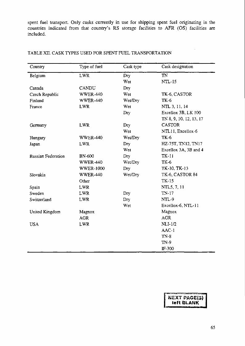
spent fuel transport. Only casks currently in use for shipping spent fuel originating in thecountries indicated from that country's RS storage facilities to APR (OS) facilities areincluded.
TABLE Xn. CASK TYPES USED FOR SPENT FUEL TRANSPORTATION
Country
Belgium
CanadaCzech RepublicFinlandFrance
Germany
HungaryJapan
Russian Federation
Slovakia
SpainSwedenSwitzerland
United Kingdom
USA
Type of fuel
LWR
CANDUWWER-440WWER-440LWR
LWR
WWER-440LWR
BN-600WWER-440WWER-1000WWER-440OtherLWRLWRLWR
MagnoxAGRLWR
Cask type
DryWetDryWetWet/DryWetDry
DryWetWet/DryDryWetDryWet/DryDryWet/Dry
DryDryWet
Cask designation
TNNTL-15
TK-6, CASTORTK-6NTL3, 11, 14Excellox3B,LK100TN8, 9, 10, 12, 13, 17CASTORNTLll,Excellox-6TK-6HZ-75T,TN12,TN17Excellox 3A, 3B and 4TK-11TK-6TK-10, TK-13TK-6, CASTOR 84TK-15NTL5.7, 11TN-17NTL-9Excellox-6, NTL-11MagnoxAGRNLI-1/2AAC-1TN-8TN-9IF-300
NEXT PAGc(3)left BLANK
65

APPENDICES A-C
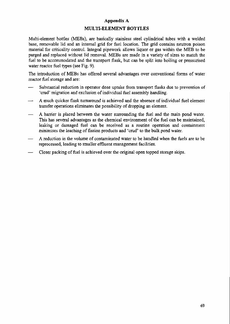
Appendix A
MULTI-ELEMENT BOTTLES
Multi-element bottles (MEBs), are basically stainless steel cylindrical tubes with a weldedbase, removable lid and an internal grid for fuel location. The grid contains neutron poisonmaterial for criticality control. Integral pipework allows liquor or gas within the MEB to bepurged and replaced without lid removal. MEBs are made in a variety of sizes to match thefuel to be accommodated and the transport flask, but can be split into boiling or pressurisedwater reactor fuel types (see Fig. 9).The introduction of MEBs has offered several advantages over conventional forms of waterreactor fuel storage and are:
— Substantial reduction in operator dose uptake from transport flasks due to prevention of'crud' migration and exclusion of individual fuel assembly handling.
— A much quicker flask turnaround is achieved and the absence of individual fuel elementtransfer operations eliminates the possibility of dropping an element.
— A barrier is placed between the water surrounding the fuel and the main pond water.This has several advantages as the chemical environment of the fuel can be maintained,leaking or damaged fuel can be received as a routine operation and containmentminimises the leaching of fission products and 'crud' to the bulk pond water.
— A reduction in the volume of contaminated water to be handled when the fuels are to bereprocessed, leading to smaller effluent management facilities.
— Closer packing of fuel is achieved over the original open topped storage skips.
69
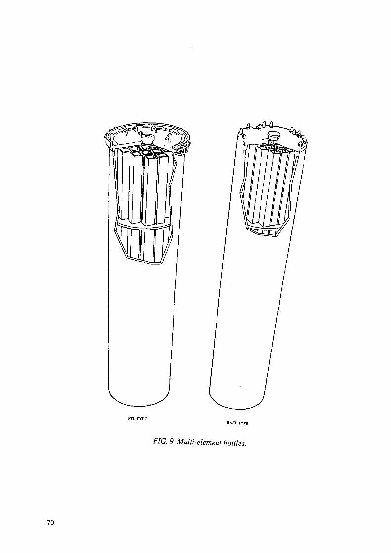
NTL TYPEBNFL TYPE
FIG. 9. Multi-element bottles.
70
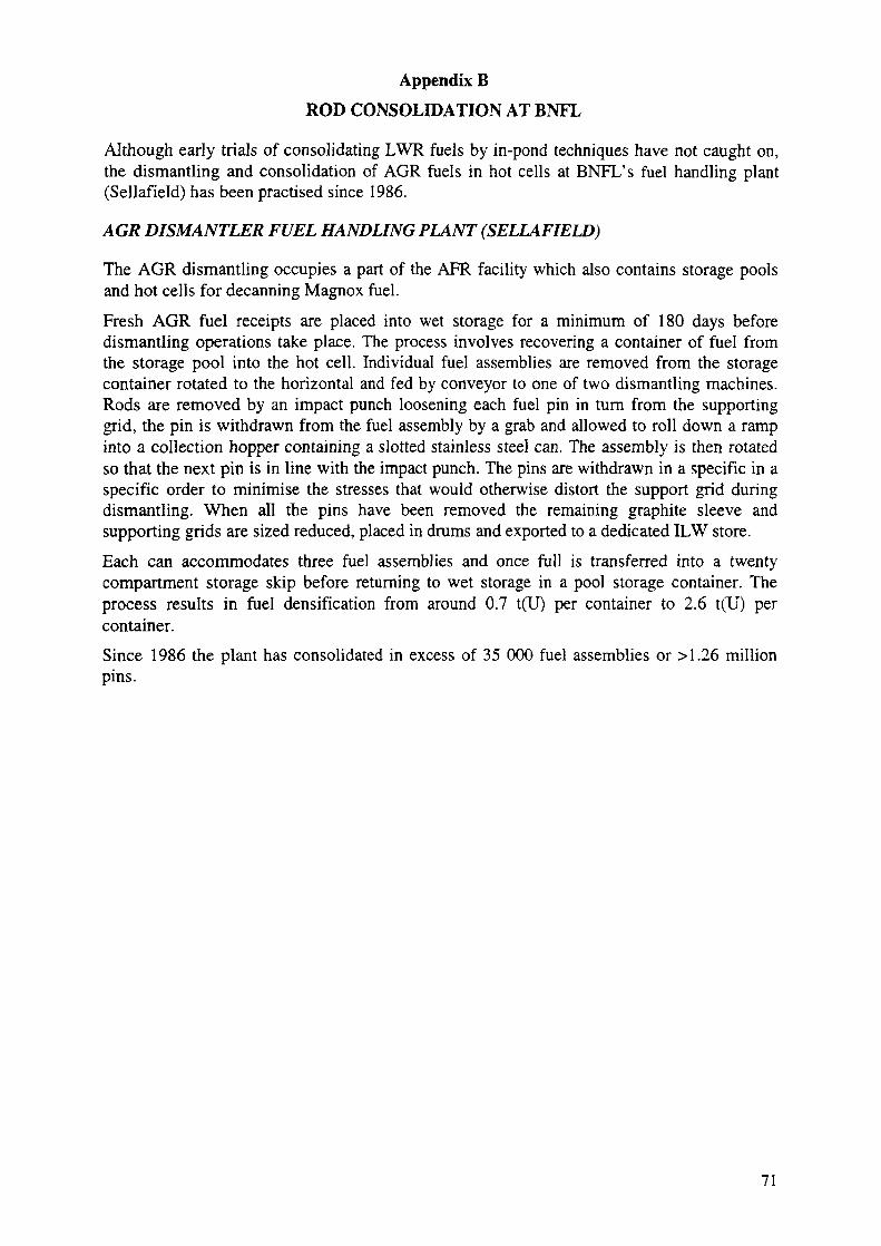
Appendix BROD CONSOLIDATION AT BNFL
Although early trials of consolidating LWR fuels by in-pond techniques have not caught on,the dismantling and consolidation of AGR fuels in hot cells at BNFL's fuel handling plant(Sellafield) has been practised since 1986.
AGR DISMANTLER FUEL HANDLING PLANT (SELLAFIELD)
The AGR dismantling occupies a part of the APR facility which also contains storage poolsand hot cells for decanning Magnox fuel.
Fresh AGR fuel receipts are placed into wet storage for a minimum of 180 days beforedismantling operations take place. The process involves recovering a container of fuel fromthe storage pool into the hot cell. Individual fuel assemblies are removed from the storagecontainer rotated to the horizontal and fed by conveyor to one of two dismantling machines.Rods are removed by an impact punch loosening each fuel pin in turn from the supportinggrid, the pin is withdrawn from the fuel assembly by a grab and allowed to roll down a rampinto a collection hopper containing a slotted stainless steel can. The assembly is then rotatedso that the next pin is in line with the impact punch. The pins are withdrawn in a specific in aspecific order to minimise the stresses that would otherwise distort the support grid duringdismantling. When all the pins have been removed the remaining graphite sleeve andsupporting grids are sized reduced, placed in drums and exported to a dedicated ILW store.Each can accommodates three fuel assemblies and once full is transferred into a twentycompartment storage skip before returning to wet storage in a pool storage container. Theprocess results in fuel densification from around 0.7 t(U) per container to 2.6 t(U) percontainer.Since 1986 the plant has consolidated in excess of 35 000 fuel assemblies or >1.26 millionpins.
71

Appendix CCONTAINER DESCRIPTIONS
GNS/GNB CASTOR type casksGeneral descriptionCASTOR casks consist of a thick-walled ductile cast iron body and a lid system. The body iscast in one piece. Four trunnions are bolted on, two at the head and two at the bottom end ofthe body. Cooling fins are included on the outside body except on casks with low heat load.Impact limiters are attached at the top and bottom of the cask during transportation.The ductile cast iron wall of the cask body serves as a gamma and neutron shield. Foradditional neutron shielding, if necessary, concentric rows of axial borings in the wall of thecask body are filled with polyethylene rods. The cask bottom and secondary lid have a slab ofthe same material inserted for neutron shielding.The cask is closed with a double barrier lid system. It consists of a primary and a secondary lidinstalled one on top of the other. The lids are constructed of stainless steel and bolted to thecask body. The primary lid has a typical overall thickness in the range of 250 to 300 mm. Ithas penetrations for flushing, venting, and vacuum drying the cask cavity as well as for leaktesting the lid seals. The penetrations are sealed in an equivalent way. The secondary lid has atypical overall thickness in the range of 100 mm. It has equivalently sealed penetrations forpressurising the lid interspace, monitoring this pressure, and performing the leaktightnessmeasurements.Both lids are equipped with multiple seals consisting of metal gaskets and elastomer O rings.The metal gaskets fulfil the long term helium leak rate requirement of a maximum leak rate of10~7mbar litre/s. During storage, the interspace between the lids is pressurised with helium toapproximately 6 bar. This overpressure is continuously monitored by a pressure gauge fitted tothe secondary lid. Thus, the leaktightness of the lid system is proven during the total storageperiod (see Fig. 10). The fuel basket accepts the spent fuel assemblies and ensures thatcriticality will not occur. The basket is of welded construction and is made of stainless steeland borated stainless steel sections. Its design is adapted to the particular spent nuclear fuelinventory.
The cask inner cavity has a nickel coating to prevent corrosion and enable easydecontamination. The outside of the cask body is protected by a multi-layer epoxy resincoating in the fin area and nickel coating on the head and bottom parts. The cask cavity isbackfilled with helium, which serves as an internal heat transfer medium as well as inhibitingcorrosion. The main characteristics of different CASTOR cask types are shown in Table XTTTwhile pictures of various CASTOR cask can be found in previous IAEA publications [2, 5, 6].
CASTOR Cask Loading Operation
Normally the spent fuel to be stored is loaded into CASTOR casks in the reactors spent fuelstorage pool. After spent fuel assemblies have been loaded, the primary lid, equipped withmetal and 0 ring gaskets, is lowered under water in place on the cask. The cask is raised to thesurface of the pool and the water is drained from the storage cask. The cask is moved to awork area and its outer surface is decontaminated. The primary lid bolts are installed and thecask is vacuum dried. The cask cavity dryness and primary lid leak tightness are measured.The cask cavity is backfilled with helium and vent and drain covers are installed and leaktested. The secondary lid is placed on the cask and its lid bolts are installed.
72
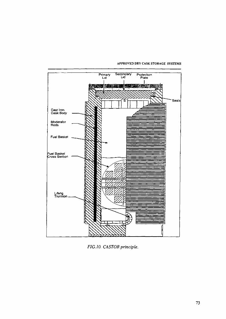
APPROVED DRY CASK STORAGE SYSTEMS
Primary Secondary ProtectionLid L|d Plate
FIG. 10. CASTOR principle.
73
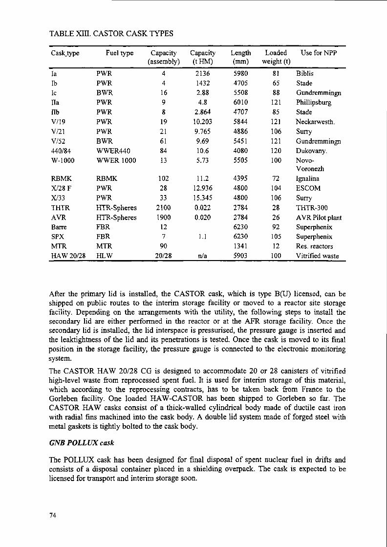
TABLE Xffi. CASTOR CASK TYPES
Casktype
laIbIcHanbV/19V/21V/52440/84W-1000
RBMKX/28FX/33THTRAYRBarreSPXMTRHAW 20/28
Fuel type
PWRPWRBWRPWRPWRPWRPWRBWRWWER440WWER 1000
RBMKPWRPWRHTR-SpheresHTR-SpheresFBRFBRMTRHLW
Capacity(assembly)
4416981921618413
1022833
21001900
127
9020/28
Capacity(tHM)
213614322.884.8
2.86410.2039.7659.6910.65.73
11.212.93615.3450.0220.020
1.1
n/a
Length(mm)5980470555086010470758444886545140805505
439548004800278427846230623013415903
Loadedweight (t)
81658812185121106121120100
7210410628269210512
100
UseforNPP
BiblisStadeGundremmingnPhillipsburgStadeNeckarwesth.SurryGundremmingnDukovany.Novo-VoronezhIgnalinaESCOMSurryTHTR-300AYR Pilot plantSuperphenixSuperphenixRes. reactorsVitrified waste
After the primary lid is installed, the CASTOR cask, which is type B(U) licensed, can beshipped on public routes to the interim storage facility or moved to a reactor site storagefacility. Depending on the arrangements with the utility, the following steps to install thesecondary lid are either performed in the reactor or at the AFR storage facility. Once thesecondary lid is installed, the lid interspace is pressurised, the pressure gauge is inserted andthe leaktightness of the lid and its penetrations is tested. Once the cask is moved to its finalposition in the storage facility, the pressure gauge is connected to the electronic monitoringsystem.The CASTOR HAW 20/28 CG is designed to accommodate 20 or 28 canisters of vitrifiedhigh-level waste from reprocessed spent fuel. It is used for interim storage of this material,which according to the reprocessing contracts, has to be taken back from France to theGorleben facility. One loaded HAW-CASTOR has been shipped to Gorleben so far. TheCASTOR HAW casks consist of a thick-walled cylindrical body made of ductile cast ironwith radial fins machined into the cask body. A double lid system made of forged steel withmetal gaskets is tightly bolted to the cask body.
GNB POLLUX cask
The POLLUX cask has been designed for final disposal of spent nuclear fuel in drifts andconsists of a disposal container placed in a shielding overpack. The cask is expected to belicensed for transport and interim storage soon.
74

The POLLUX cask concept has been developed for direct disposal of spent fuel in saltformations and takes into account the postulated conditions of the repository. The POLLUXconsists of a thick walled inner steel cask and a second outer container designed for shieldingrequirements during transport, interim storage and final disposal.
CONSTOR steel-concrete cask
The CONSTOR steel-concrete cask initially was developed for transport and storage of spentRBMK fuel, but further development was made to adjust the parameters to accommodateother fuel types too.
The CONSTOR RBMK cask consists of an outer and an inner shell made of steel. The spacebetween the two liners is filled with heavy concrete for gamma and neutron shielding. Insidethe concrete, steel reinforcement is arranged to improve the strength and heat removalproperties. The cask bottom has the same sandwich design as the wall. At the lid end, theshells are welded to a ring made of forged steel. The trunnions for lifting and handling areattached to this ring.
The lid system is designed as a multi-barrier system. The bolted primary lid fulfils strengthand shielding functions. For temporary shielding this lid is made leaktight by means of anelastomer seal. The sealing plate and the secondary lid are welded to the forged steel ring afterloading and servicing of the cask. These two welded lids, together with the inner and outershell (including their bottom plates), represent the double barrier system.
The RBMK spent fuel bundles are positioned in a basket inside the cask. The capacity of thestandardised basket is 102 bundles (half length). The total mass of the CONSTOR RBMKcask including impact limiters, loaded with the 102 bundle basket is approx. 96 500 kg. Theaverage enrichment is 2%, the average bumup is 20 GW d/t, and the minimum cooling time is5 years, resulting in 7.65 kW heat load for a cask.
The type B(U) licensing of the CONSTOR RBMK cask was initiated in The Russian Federationin 1994 and the formal completion is expected for 1998.
HOLTEC International, Inc., HI-STAR/HI-STORM 100 System
The HOLTEC International (HOLTEC) HI-STAR 100 System (HOLTEC InternationalStorage, Transport and Repository Cask System) consists of metal canisters (referred to asmulti-purpose canisters or MPCs) designed to store spent fuel assemblies in a dry, inertenvironment and a metal overpack for storage and transport. The canisters are referred to asmulti-purpose canisters because of the potential use of the canister with an appropriateoverpack for spent fuel disposal. However, use for disposal can not be confirmed untilcompletion of the final repository design. The HI-STAR 100 System includes three differentMPC designs with different internal fuel baskets for storage of either PWR or BWR spent fuelassemblies. The spent fuel parameters for each basket are provided in Table XTV. A sketch ofthe HI-STAR 100 system is presented in Figure 11 [17].Holtec has also designed a concrete and steel vertical storage overpack, the HOLTEC HI-STORM 100 Storage Overpack, that could be used for on-site spent fuel storage instead of themetal storage and transport overpack. The main structural components are provided by carbonsteel and shielding is provided by concrete. The storage overpack has convective coolingducts to allow for passive cooling of the HOLTEC HI-STAR 100 MPC. The overpack isenclosed by cylindrical steel shells, a thick steel baseplate, and a bolted-on lid. Four
75
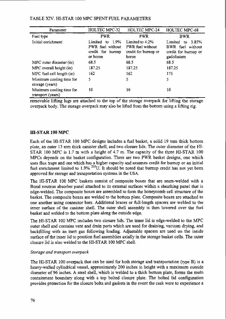
TABLE XIV. HI-STAR 100 MFC SPENT FUEL PARAMETERS
ParameterFuel typeInitial enrichment
MFC outer diameter (in)MFC overall height (in)MFC fuel cell length (in)Minimum cooling time forstorage (years)Minimum cooling time fortransport (years)
HOLTEC MFC-32PWR
Limited to 1.9%PWR fuel withoutcredit for bumupor boron68.5187.251625
10
removable lifting lugs are attached to the top ofoverpack body. The storage overpack may also be
HOLTEC MFC-24PWR
Limited to 4.2%PWR fuel withoutcredit for burnup orboron68.5187.251625
10
the storage overpacklifted from the bottom
HOLTEC MPC-68BWR
Limited to 3.85%BWR fuel withoutcredit for burnup orgadolinium68.5187.251755
10
for lifting the storageusing a lifting rig.
ffl-STAR 100 MFC
Each of the ffl-STAR 100 MFC designs includes a fuel basket, a solid 19 mm thick bottomplate, an outer 13 mm thick canister shell, and two closure lids. The outer diameter of the HI-STAR 100 MFC is 1.7 m with a height of 4.7 m. The capacity of the three HI-STAR 100MFCs depends on the basket configuration. There are two PWR basket designs, one whichuses flux traps and one which has a higher capacity and assumes credit for burnup or an initialfuel enrichment limited to 1.9% 235U. It should be noted that burnup credit has not yet beenapproved for storage and transportation systems in the USA.The HI-STAR 100 MFC baskets consist of composite boxes that are seam-welded with aBoral neutron absorber panel attached to its external surfaces within a sheathing panel that isedge-welded. The composite boxes are assembled to form the honeycomb cell structure of thebasket. The composite boxes are welded to the bottom plate. Composite boxes are attached toone another using connector bars. Additional braces or full-length spacers are welded to theinner surface of the canister shell. The outer shell assembly is then lowered over the fuelbasket and welded to the bottom plate along the outside edge.The ffl-STAR 100 MFC includes two closure lids. The inner lid is edge-welded to the MFCouter shell and contains vent and drain ports which are used for draining, vacuum drying, andbackfilling with an inert gas following loading. Adjustable spacers are used on the insidesurface of the inner lid to position fuel assemblies axially in the storage basket cells. The outerclosure lid is also welded to the HI-STAR 100 MFC shell.
Storage and transport overpack
The ffl-STAR 100 overpack that can be used for both storage and transportation (type B) is aheavy-walled cylindrical vessel, approximately 200 inches in height with a maximum outsidediameter of 96 inches. A steel shell, which is welded to a thick bottom plate, forms the maincontainment boundary along with a top bolted closure plate. The bolted lid configurationprovides protection for the closure bolts and gaskets in the event the cask were to experience a
76
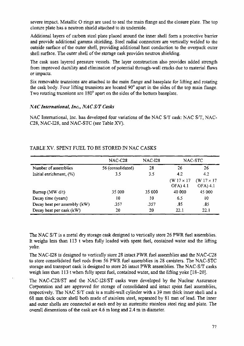
severe impact. Metallic O rings are used to seal the main flange and the closure plate. The topclosure plate has a neutron shield attached to its underside.Additional layers of carbon steel plate placed around the inner shell form a protective barrierand provide additional gamma shielding. Steel radial connectors are vertically welded to theoutside surface of the outer shell, providing additional heat conduction to the overpack outershell surface. The outer shell of the storage cask provides neutron shielding.The cask uses layered pressure vessels. The layer construction also provides added strengthfrom improved ductility and elimination of potential through-wall cracks due to material flawsor impacts.Six removable trunnions are attached to the main flange and baseplate for lifting and rotatingthe cask body. Four lifting trunnions are located 90° apart in the sides of the top main flange.Two rotating trunnions are 180° apart on the sides of the bottom baseplate.
NACInternational, Inc., NACS/T Casks
NAC International, Inc. has developed four variations of the NAC S/T cask: NAC S/T, NAC-C28, NAC-I28, and NAC-STC (see Table XV).
TABLE XV. SPENT FUEL TO BE STORED IN NAC CASKS
Number of assembliesInitial enrichment, (%)
Burnup (MW d/t)Decay time (years)Decay heat per assembly (kW)Decay heat per cask (kW)
NAC-C2856 (consolidated)
3.5
3500010
.35720
NAC-I28283.5
3500010
.35720
NAC-STC264.2
(W17x 17OF A) 4.140000
6.5.85
22.1
264.2
(W 17 x 17OF A) 4.1
4500010.85
22.1
The NAC S/T is a metal dry storage cask designed to vertically store 26 PWR fuel assemblies.It weighs less than 113 t when fully loaded with spent fuel, contained water and the liftingyoke.The NAC-I28 is designed to vertically store 28 intact PWR fuel assemblies and the NAC-C28to store consolidated fuel rods from 56 PWR fuel assemblies in 28 canisters. The NAC-STCstorage and transport cask is designed to store 26 intact PWR assemblies. The NAC-S/T casksweigh less than 113 t when fully spent fuel, contained water, and the lifting yoke [18-20].The NAC-C28/ST and the NAC-I28/ST casks were developed by the Nuclear AssuranceCorporation and are approved for storage of consolidated and intact spent fuel assemblies,respectively. The NAC S/T cask is a multi-wall cylinder with a 39 mm thick inner shell and a68 mm thick outer shell both made of stainless steel, separated by 81 mm of lead. The innerand outer shells are connected at each end by an austenitic stainless steel ring and plate. Theoverall dimensions of the cask are 4.6 m long and 2.4 m in diameter.
77

BOLTED CASK LID
SHIELD
CASK OUTERSHELL
NEUTRONSHIELD ..
CARBON STEELGAUUA SHIELD
CANISTEROUTER LIDINNER LID
BASKET
CANISTER SHELL
CASK TOP TRUNNION(4) REQUIRED <? 90e
CANISTER BA?E PLATE
CASK INNER SHELL
(2) CASK BOTTOUTRUNNIONS
(NOT VISIBLE)
CASK BASE PLATE
FIG. 11. HI-STAR 100.
NAC also plans to license a variation of the NAC-STC which would house a sealed metalcanister for containing spent fuel in the place of the integral basket in the NAC-STC, referredto as the NAC MFC.
Cask body
The cask body for the four cask designs is similar. The range of dimensions is included in thisdescription. The cask body consists of a cylindrical, multi-walled construction of stainless
78
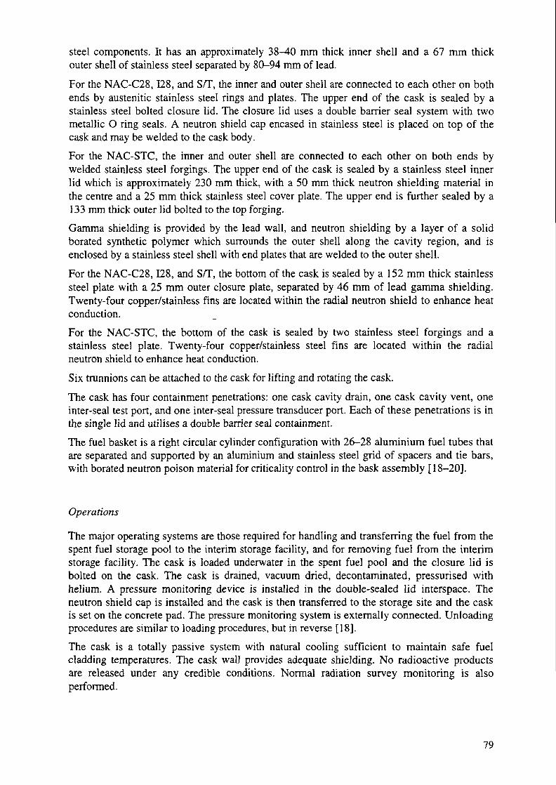
steel components. It has an approximately 38-40 mm thick inner shell and a 67 mm thickouter shell of stainless steel separated by 80-94 mm of lead.For the NAC-C28,128, and S/T, the inner and outer shell are connected to each other on bothends by austenitic stainless steel rings and plates. The upper end of the cask is sealed by astainless steel bolted closure lid. The closure lid uses a double barrier seal system with twometallic O ring seals. A neutron shield cap encased in stainless steel is placed on top of thecask and may be welded to the cask body.For the NAC-STC, the inner and outer shell are connected to each other on both ends bywelded stainless steel forgings. The upper end of the cask is sealed by a stainless steel innerlid which is approximately 230 mm thick, with a 50 mm thick neutron shielding material inthe centre and a 25 mm thick stainless steel cover plate. The upper end is further sealed by a133 mm thick outer lid bolted to the top forging.Gamma shielding is provided by the lead wall, and neutron shielding by a layer of a solidborated synthetic polymer which surrounds the outer shell along the cavity region, and isenclosed by a stainless steel shell with end plates that are welded to the outer shell.For the NAC-C28,128, and S/T, the bottom of the cask is sealed by a 152 mm thick stainlesssteel plate with a 25 mm outer closure plate, separated by 46 mm of lead gamma shielding.Twenty-four copper/stainless fins are located within the radial neutron shield to enhance heatconduction.For the NAC-STC, the bottom of the cask is sealed by two stainless steel forgings and astainless steel plate. Twenty-four copper/stainless steel fins are located within the radialneutron shield to enhance heat conduction.Six trunnions can be attached to the cask for lifting and rotating the cask.The cask has four containment penetrations: one cask cavity drain, one cask cavity vent, oneinter-seal test port, and one inter-seal pressure transducer port. Each of these penetrations is inthe single lid and utilises a double barrier seal containment.The fuel basket is a right circular cylinder configuration with 26-28 aluminium fuel tubes thatare separated and supported by an aluminium and stainless steel grid of spacers and tie bars,with borated neutron poison material for criticality control in the bask assembly [18-20].
Operations
The major operating systems are those required for handling and transferring the fuel from thespent fuel storage pool to the interim storage facility, and for removing fuel from the interimstorage facility. The cask is loaded underwater in the spent fuel pool and the closure lid isbolted on the cask. The cask is drained, vacuum dried, decontaminated, pressurised withhelium. A pressure monitoring device is installed in the double-sealed lid interspace. Theneutron shield cap is installed and the cask is then transferred to the storage site and the caskis set on the concrete pad. The pressure monitoring system is externally connected. Unloadingprocedures are similar to loading procedures, but in reverse [18],The cask is a totally passive system with natural cooling sufficient to maintain safe fuelcladding temperatures. The cask wall provides adequate shielding. No radioactive productsare released under any credible conditions. Normal radiation survey monitoring is alsoperformed.
79

NAC Universal MFC system (VMS)
NAC International, Inc. has designed a canister-based system for the storage and transport ofspent nuclear fuel. The system is designated the universal MFC System — the storagecomponent is designated the universal storage system. NAC submitted a safety analysis reportfor storage to the NRC in September 1997. The SAR for the universal transportation systemwas submitted earlier in April 1997. The canisters are referred to as multi-purpose canisters(MFCs) because of the potential use of the canister with an appropriate overpack for spentfuel disposal. However, use for disposal can not be confirmed until completion of the finalrepository design.
Description
The universal storage system (USS) is a spent fuel dry storage system that uses a stainlesssteel transportable storage canister with a welded closure and a vertical concrete cask to storeintact spent fuel assemblies. The system also includes a transfer cask. The transportablestorage canister is designed and fabricated to meet the requirements for transport in theuniversal transport cask. Figure 12 presents a diagram of the NAC UMS storage system.The UMS storage system is designed to store 24 PWR fuel assemblies or 56 BWR fuelassemblies. PWR fuel requirements are a maximum initial enrichment of 4.2% 235U, amaximum burnup of 40 000 MW d/t HM and a minimum decay time of 5 years after reactordischarge. BWR fuel requirements are a maximum initial enrichment of 3.75% 235U, amaximum burnup of 40 000 MW d/t HM and a minimum decay time of 5 years after reactordischarge.
Transportable canister
The loaded canister is moved to and from the concrete cask using the transfer cask. Thetransfer cask provides radiation shielding while the canister is being closed and sealed andwhile the canister is being transferred. The canister is placed in the concrete cask bypositioning the transfer cask with the loaded canister on top of the concrete cask and loweringthe canister into the concrete cask.The transportable storage canister consists of a stainless steel canister that contains the fuelbasket structure and payload. The canister is defined as the confinement for the spent fuelduring storage and is provided with a double-welded closure system. The canister consists of acylindrical 16 mm thick stainless steel shell with a 44 mm thick stainless steel bottom plateand a stainless steel lid support ring. The basket assembly is placed inside the canister andprovides the structural support and the primary heat transfer path for the fuel assemblies whilemaintaining a subcritical configuration for the spent fuel.The shield lid assembly is a 178 mm thick stainless steel disk that is positioned on the shieldlid support ring above the basket assembly. The shield lid is welded to the canister while thecanister inside the transfer cask is in the work area after removal from the spent fuel pool.Two penetrations through the shield lid are provided for draining, vacuum drying, andbackfilling the canister with helium. Following removal of water from the system, the systemis vacuum dried and backfilled with helium and it is pressure tested and leak-tested to ensurethe required leaktightness has been achieved.The structural lid is a 76 mm stainless steel disk positioned on top of the shield lid and weldedto the shell after the shield lid is welded in place and the canister is drained, dried, andbackfilled with helium [21].
80

Ventilation openings for air circulation
Portland cement
35" carbon-steel liner
Concrete thickness:21 indies
Vertical concrete storageoverpack with canister
FIG. 12. NAC VMS.
Concrete storage cask
The vertical concrete cask provides structural support, shielding, protection fromenvironmental conditions, and natural convection cooling of the canister during storage. Theconcrete wall and steel liner provide the neutron and gamma radiation shielding for the
81

storage cask. Inner and outer reinforcing steel rebar assemblies are contained within theconcrete. The concrete cask has an annular air passage to allow the natural circulation of airaround the canister to remove the decay heat from the spent fuel stored in the transportablestorage canister. The top of the concrete cask is closed by a shield plug and lid whichincorporates a carbon steel plate as gamma radiation shielding and NS-4-FR as neutronradiation shielding. A carbon steel lid that provides additional gamma radiation shielding isinstalled above the shield lid [21].
Transfer equipment
The transfer cask is used for the vertical transfer of the canister between work stations and theconcrete cask, or transport cask. The transfer cask incorporates a multi-wall design whichlimits the contact radiation dose to less than 3 mSv/hour. The transfer cask design alsoincorporates a top retaining ring, which is bolted in place, that prevents a loaded canister frombeing inadvertently removed through the top of the transfer cask. The transfer cask hasretractable bottom shield doors to facilitate the transfer of the canister from the transfer caskinto the concrete storage cask or transportation cask. Ancillary equipment needed to use theUSS are: automated or manual welding equipment; an air pallet or hydraulic roller skid tomove the concrete cask on and off the heavy haul trailer and to position the concrete cask onthe storage pad; suction pump, vacuum drying, helium backfill and leak detection equipment;a heavy haul trailer or transporter for transport of the concrete cask to the storage pad;alignment plates and hardware to position the transfer cask with respect to the storage ortransport cask; and a lifting yoke for the transfer cask and lifting slings for the canister andcanister lids [21].
Ontario Hydro, Picketing dry storage container
The Pickering dry storage container (DSC) is a rectangular section container made of adouble carbon-steel shell filled with reinforced high density concrete. The container design isshown in Figure 13. It measures 2.42 m x 2.12 m by 3.55 m in height. The thickness of eachcarbon-steel shell is 13 mm. The inner liner is the primary containment boundary. Thefunction of the outer shell is primarily to enhance structural strength, and to facilitatedecontamination. The payload chamber (cavity) is designed to hold four standard fuel storagemodules (96 fuel bundles each) and measures 1.34 m x 1.05 m by 2.52 m in height. Helium isused as the cover gas in the DSC cavity. The weight of the container is approximately 53 t.The loaded DSC weighs about 63 t.The DSC is designed with provisions for attaching safeguards seals. Two separate U-shaped25 mm OD stainless steel tubes are embedded in the DSC walls and floor in the plane of theouter reinforcing grid. These tubes are placed so that each tube runs across the centre of theopposite container walls. Two similar tubes are embedded in the DSC lid and run diagonallyacross the lid. These tubes are provided for attaching IAEA COBRA seals (body and lid) andmechanical seals (lid only).The concrete in a DSC provides radiation shielding and structural strength while maintainingadequate heat dissipation. The DSC high density reinforced concrete is composed of Portlandcement, water, and high density aggregates. The thickness of the concrete wall is 520 mm.The container closure system consists of a lid, guide pins and a closure weld around theperimeter of the container. The lid measures 2.42 x 2.12 x 0.52 m and is made of a carbonsteel shell encasing a slab of reinforced heavy concrete. The lid base plate is part of the DSC
82

containment boundary. The DSC lid is seal-welded to the container body by an automatedprocess. All containment welds are tested and inspected to specifications.The DSC is designed to store six year-cooled irradiated fuel with a heat load of 7.4 W perbundle. Helium is used as the cavity atmosphere.The DSC is designed to withstand tornado winds, as well as tornado generated missileimpacts, 2.8 m free drop, immersion under 200 m of water, seismic activity up to the designbasis earthquake (DBE) for Pickering, and an internal overpressure of 100 kPa.
Shield Rate
Vent Port
Drain Port
Seal/StiucturalWeld
Fuel Modules(Total 4)
ReinforcedHigh Density
Concrete
Steel InnerUner
Steef OuterUner
FIG. 13. Pickering dry storage container (DSC).
The container handling system consists of lifting plates, a lifting beam with trunnions and lidlifting lugs. The lugs are designed to be removable from the container. The lifting beam isdedicated to the DSC handling and is compatible with the fuel pool crane. The lifting beam, isdesigned to engage into the lifting plates attached on the DSC body.
83
The lid will be securely attached to the DSC base using an in-bay clamp during the entireoperation in the bay in order to provide protection during credible accident scenarios. The in-bay clamp will be replaced by the transfer clamp in preparation to transport the container tothe DSF.
Sierra Nuclear
VSC-24 and TranStor systems
The VSC-24 system is a vertical concrete cask system that stores 24 PWR spent fuelassemblies. Its components include a multi-assembly sealed basket (MSB), a ventilatedconcrete cask (VCC), and a MSB transfer cask (MTC). The welded MSB providesconfinement for the storage and transfer of spent nuclear fuel. The VCC provides radiationshielding while allowing cooling of the MSB and fuel by natural convection during storage.
Sierra Nuclear Corporation has designed a modified version of the VSC-24 referred to as theTranstor system and has applied for licensing for storage and for transport of spent fuel.
The TranStor System includes a sealed basket containing fuel assembly sleeves, a shippingcask with impact limiters, an on-site concrete storage cask, and an on-site transfer cask. Thesealed basket is used in combination with the transfer cask and the storage cask componentsfor onsite storage of spent nuclear fuel. Offsite shipping of spent fuel is performed using thesealed basket and the shipping cask components.
VSC-24 storage system components
The MSB consists of a steel cylindrical shell with a shield plug and steel cover plates weldedat each end. The shell length is fuel specific and varies from 4.1 to 4.6 m, the diameter is 1.6m, and the shell thickness is 25 mm. An internal fuel basket is designed to hold 24 PWR spentfuel assemblies. The steel basket is a welded structure consisting of 24 square storagelocations. Support in the horizontal direction is provided by curved supports located at eachend and the centre of the basket assembly. The basket is coated with a CarboZinc 11 coatingfor corrosion protection. The MSB is installed vertically in the VCC.
The VCC is a reinforced concrete cask. The VCC has air inlets near the bottom of the concretecask and air outlets near the top of the concrete cask. The internal cavity of the VCC as wellas the air inlets and outlets are steel-lined. After the MSB is inserted in the VCC, a shield ringis placed over the MSB/VCC gap and the cask weather cover is installed.
A transfer cask is used to shield, support and protect the MSB during fuel loading and transferto the VCC. It is a shielded lifting devise with inner and outer structural steel cylinders whichhouse lead and solid RX-277 neutron shield cylinders.
Auxiliary equipment includes a vacuum drying system, trailer, and cask skid used during caskloading and transfer operations [18, 22].
The VSC-24 system is designed to store only intact, unconsolidated PWR fuel assembliesmeeting the specifications of the cask Certificate of Compliance. The fuel characteristics thatapply to the VSC-24 system are presented in Table XVI [18, 22].
84

TranStor system description
The PWR fuel assembly basket has 24 cells to accommodate one of the following: 24 PWRassemblies, 20 PWR assemblies and 4 special cans of failed or partial fuel or fuel debris, orany intermediate combination of PWR assemblies and special cans. The BWR fuel assemblybasket has 61 cells to accommodate the following: 61 BWR assemblies with or withoutchannels, 52 assemblies and 8 special cans of failed or partial fuel, or any intermediatecombination of fuel assemblies and special cans [23].
The TranStor basket is a cylindrical steel canister designed for storage and shipping ofirradiated spent fuel. Its components include a storage sleeve assembly, shell assembly, shieldlid, and structural lid. The shell and lids provide containment and confinement boundaries,shielding, and lifting capability for the basket. The sleeve assembly provides support to thebasket contents and is designed to accommodate intact fuel, failed fuel, fuel debris, damagedfuel, non-fuel bearing components, fuel assembly hardware, and greater-than-Class C (GTCC)low-level radioactive waste. The TranStor baskets vary in length from 114 inches to 180inches, depending on the length of the fuel assemblies. An axial spacer, of an appropriatelength is inserted between the basket and the shipping cask closure lid to maintain the basket'sposition during shipping.
The shell assembly consists of a cylindrical shell with a bottom plate and the shield lidsupport ring. The sleeve assembly is placed inside the shell and consists of square tubes whichinclude neutron poison sheets to maintain a subcritical configuration for fresh, unirradiatedfuel in unborated water. The shield lid assembly is a thick steel disk that is positioned on theshield lid support ring above the sleeve assembly after the fuel has been loaded into thebasket, while the basket is in the spent fuel pool. The shield lid is welded to the basket whilein the decontamination pit. Two penetrations through this shield lid are provided for draining,vacuum drying, and backfilling the basket with helium.
The structural lid is a steel disk that is positioned on top of the shield lid and welded to thebasket shell after the shield lid is welded in place. The structural lid has a penetration foraccess to the vent and drain connections in the shield lid. The structural lid is seal weldedonce the helium backfield process has been completed.
The concrete cask used in the TranStor system is very similar in materials, size andconstruction to the concrete cask that is part of the VSC-24 storage system (see Fig. 14) [23].
Operations
During VSC-24 and TranStor system loading, the MTC containing an empty MSB ispositioned in the spent fuel pool. Fuel assemblies meeting the fuel specifications are loadedinto the MSB. A shield ring is placed on the MSB and the MTC is used to remove the MSBfrom the spent fuel pool. The MSB and MTC are drained and decontaminated. The MSB isvacuum dried, seal welded, and backfilled with helium. The seal welds are leak tested. TheMSB, in the MTC, is transferred and is positioned vertically over the VCC. The MSB islowered into the VCC and the shield ring is placed over the MSB/VCC gap and the weathercover is installed. The VCC is then transferred to the ISFSI via a truck trailer and is positionedon the storage pad using a hydraulic roller skid.
85

Cask Lid
Multi-AssemblySealed Basket
Steel Liner
Concrete
Air Inlet Duct
Air Entrance
FIG. 14. TranStor system.
Transnucleaire
TN24 Transport/storage cask
The TN24 is designed as a dual purpose storage and transport cask. The TN24 cask family hasbeen developed for the transport and storage of spent fuel assemblies with a cooling time of 5to 10 years. Each cask version complies with the IAEA transport regulations. TN casks arealso used for storage in the USA and Belgium. The main characteristics of the casks in theTN24 cask family are provided in Table XVII.
Depending on cooling time and fuel characteristics, the cask capacity varies from 24 to 32PWR fuel assemblies, while remaining compatible in weight and size with the existingtransport equipment.
86

TABLE XVI. CHARACTERISTICS OF SPENT FUEL TO BE STORED IN SIERRANUCLEAR STORAGE SYSTEMS
Fuel Characteristic
Fuel class/type
VSC-24
PWR: B&W, Mark B, 15 x 15,CE/Siemens 15x15
CE 16 x 16, Westinghouse 14 x 14,15 x 15, 17 x 17
TranStor
BWR,NFBC, assembly hardware,
GTCC LLW
PWR,NFBC,assemblyhardware,GTCC LLW
Fuel cladding Zircaloy cladding with no known or Can accommodate special cans of failed fuel,suspected gross cladding defects or partial fuel or fuel debris
Max decay power package 24 kW 26 kW / 24 kW for transport
Maximum bumup 51 800 MW d/t HM" 40 000 MW d/t HM (6 years) 45 000 MW
35 000 MW d/t HM (5 years)
40 000 MWd/tHM
(5 years)Minimum decay time (years) 5 See maximum bumupMaximum initial enrichment 4.2 3.7 4.2(% M5U)Number of assemblies per VSC 24 61 24
* For casks loaded with fuel assemblies having bumups greater than 35 000 MW d/t HM, specific analyses mustbe performed to demonstrate that the initial fuel clad temperature criteria are not exceeded and that neutron andgamma source strengths do not exceed the specified criteria tabulated above.
Cask construction relies upon the use of a thick forged steel wall, a typical feature of the largenumber of spent fuel transport casks.
The following description covers several cask versions that have been developed for variousfuel characteristics and operator requirements. Versions of this cask have been designed forWWER-440 and WWER-1000 fuel assemblies.
Containment
The 3 main cask containment components, a thick shell, the bottom, and the primary lid aremade from forged steel. The first two components are always made of carbon steel becausecarbon steel combines: (1) good mechanical behaviour at low temperature needed to meet 92AEA transport requirements, (2) good heat transfer and (3) well known manufacturing andinspection techniques.
The containment system is 220 mm to 350 mm thick in order to provide required gammashielding which is more than the thickness required to meet mechanical design limits. A singleforged steel cylinder is welded to a forged bottom plate.
A primary lid with metallic gaskets is bolted to the upper end of the cask to provide a leaktightseal. An optional secondary lid is also available. All sealing surfaces are covered with astainless steel overlay.
The cask cavity is protected from corrosion by zinc-aluminium spray coatings.
87
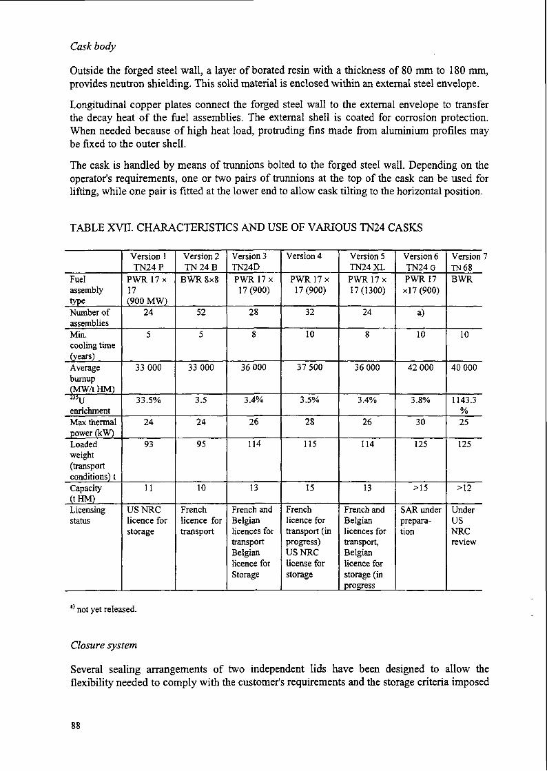
Cask body
Outside the forged steel wall, a layer of borated resin with a thickness of 80 mm to 180 mm,provides neutron shielding. This solid material is enclosed within an external steel envelope.
Longitudinal copper plates connect the forged steel wall to the external envelope to transferthe decay heat of the fuel assemblies. The external shell is coated for corrosion protection.When needed because of high heat load, protruding fins made from aluminium profiles maybe fixed to the outer shell.
The cask is handled by means of trunnions bolted to the forged steel wall. Depending on theoperator's requirements, one or two pairs of trunnions at the top of the cask can be used forlifting, while one pair is fitted at the lower end to allow cask tilting to the horizontal position.
TABLE XVH. CHARACTERISTICS AND USE OF VARIOUS TN24 CASKS
FuelassemblytypeNumber ofassembliesMin.cooling time(years)Averagebumup(MW/tHM)235u
enrichmentMax thermalpower (kW)Loadedweight(transportconditions) tCapacity(tHM)Licensingstatus
Version 1TN24P
PWR17x17(900 MW)
24
5
33000
33.5%
24
93
11
USNRClicence forstorage
Version 2TN24B
BWRSxg
52
5
33000
3.5
24
95
10
Frenchlicence fortransport
Version 3TN24DPWR17x
17(900)
28
8
36000
3.4%
26
114
13
French andBelgianlicences fortransportBelgianlicence forStorage
Version 4
PWR17x17(900)
32
10
37500
3.5%
28
115
15
Frenchlicence fortransport (inprogress)USNRClicense forstorage
Version 5TN24XLPWR17x17(1300)
24
8
36000
3.4%
26
114
13
French andBelgianlicences fortransport,Belgianlicence forstorage (inprogress
Version 6TN24GPWR17x!7(900)
a)
10
42000
3.8%
30
125
>15
SAR underprepara-tion
Version 7TN68BWR
10
40000
1143.3%25
125
>12
UnderUSNRCreview
a) not yet released.
Closure system
Several sealing arrangements of two independent lids have been designed to allow theflexibility needed to comply with the customer's requirements and the storage criteria imposed
88

by its Competent Authority. Two leaktight barriers with checkable interspace are provided tomeet transport requirements including accident conditions. Two leaktight metallic gasketswith continuously monitored helium pressurised interspace are provided during storage.Provisions have also been made to allow, welding of the secondary or a ternary lid.
The primary lid is equipped with a single opening to allow draining water from the cavity,venting, drying and backfilling with helium. This opening is connected to a draining tubereaching the lowest part of the cavity. Its leaktightness is also ensured by metallic gaskets andtest devices are provided.
Basket
The cask cavity is fitted with a removable basket designed as a structural support for the fuelassemblies. It consists of mechanically assembled partitions in borated aluminium defining anarray of cells, one for each fuel assembly. This basket technology uses borated aluminium forboth neutron attenuation (Boron 10) and heat conduction (aluminium alloy).
Operations
The cask is loaded under water in the reactor spent fuel pool using procedures similar tostandard transport casks. During transport, the cask is protected by shock absorbers. The caskis stored vertically on a concrete pad without the shock absorbers. Optionally, its top side canbe protected from an aeroplane crash by a heavy steel cover.
The two leaktight barriers are continuously monitored during storage. Maintenance operationsduring the storage period are very light, mainly limited to visual inspection and repaintingwhen needed.
Transnuclear Inc.
TN-40 cask
Cask descriptionThe TN-40 cask consists of the following components: a basket assembly for support of thefuel assemblies; a containment vessel enclosing the basket and spent fuel; a gamma shield anda neutron shield; an outer shell; a weather cover; a pressure monitoring system; and trunnions.The TN-40 containment vessel consists of an inner shell which is a welded, carbon steelcylinder with an integrally-welded, carbon steel bottom closure; a welded flange forging; aflanged and bolted carbon-steel lid with bolts; and penetration assemblies with bolts.
The cask body consists of an inner shell which is a carbon steel cylinder with a wall thicknessof 38 mm. The containment lid is 114 mm thick and is fastened to the body by 48 bolts. Thereare two penetrations in the lid, a drain opening and a vent. Each penetration has a double-sealmechanical closure. Double metallic O ring seals with interspace leakage monitoring areprovided for the lid closure. The cask cavity is pressurised above atmospheric pressure withhelium. The interspace between the metallic seals is monitored and pressurised with helium toa higher level than the cavity so that any seal leakage would be into rather than out of thecavity. A weather cover is provided above the lid.
89

A gamma shield is provided around the walls of the containment vessel by an independentshell of carbon steel which is welded to a bottom shield plate and to the closure flange. Thegamma shield completely encloses the containment vessel inner shell and bottom closure.Neutron shielding is provided by a resin compound surrounding the body. The resincompound is enclosed in long, slender aluminium containers. The array of resin filledcontainers is enclosed within a smooth outer steel shell. The aluminium also provides aconduction path for heat transfer from the cask body to the outer shell. A disk ofpolypropylene is attached to the cask lid to provide neutron shielding during storage. Fourtrunnions are attached to the cask body for lifting and rotation of the cask.
The basket structure consists of an assembly of stainless steel cells joined by a fusion weldingprocess and separated by aluminium and Boral poison plates which form a sandwich panel.The cask cavity surfaces are sprayed with metallic coating for corrosion protection. Theexternal surfaces of the cask are painted for ease of decontamination [18, 24].
Operations
The major operating systems are those required for handling and transferring spent fuel fromthe storage pool to the interim storage facility. The cask is loaded underwater in the spent fuelpool and the lid is placed on the cask. The cask is lifted to the pool surface, the lid is bolted,and the cask is drained. Next, it is vacuum dried, pressurised with helium and decontaminated.The polypropylene neutron shield disk and steel cover are then installed, and a pressuremonitoring devise is installed in the double-seal interspace. The cask is then transferred to thestorage facility and placed on the concrete storage pad. The pressure monitoring system isexternally connected and will notify the plant operators of a loss of seal integrity [18, 24].
VECTRA TECHNOLOGIES, INC.
Nuhoms storage systems
The NUHOMS family of concrete modular (silo) storage systems are designed to horizontallystore PWR and BWR spent fuel assemblies. Its main components include a stainless steel dryshielded canister (DSC) with an internal fuel basket, a concrete horizontal storage module(HSM) that protects the DSC and provides radiological shielding, a transfer cask used totransport the DSC to the HSM and to provide shielding during transfer, and a hydraulic ramsystem (HRS) used to insert the DSC into the HSM. These components will be generallydescribed in the following section, with specific dimensions provided in Table XVffl. Adiagram of the NUHOMS-24P system can be seen in Appendix D of Ref. [6].
Horizontal storage module
The horizontal storage module (HSM) is constructed of reinforced concrete, structural steel,and stainless steel. The HSM may be constructed as a single unit or as an array of modules.The HSM provides neutron and gamma shielding for the DSC. A steel support rail structureanchored inside the HSM by the interior walls supports the DSC and extends to the accessopening. Stoppers on the rails prevent horizontal movement of the DSC during a seismicevent. A vertical sliding plate, consisting of thick steel and a neutron absorbing material,covers the entrance to the HSM and is tack welded closed when the DSC is in place. Coolingof spent fuel stored in the NUHOMS system is provided by a combination of radiation,conduction, and convection. Air enters shielded passages at the front of the HSM, passes
90

around the DSC, and exits through the flow channels in the roof of the HSM. Air vents in theHSM are covered with stainless steel wire screening [18, 25-27].
Dry shielded canister
The DSC is designed to provide primary containment for spent fuel assemblies. The DSC is astainless steel cylinder, 4.6-4.7 m in length, 0.9-1.7 m in diameter, and 13-16 mm thick.Stainless steel end plates and steel end plugs filled with lead are welded to the top and bottomof the DSC with double seal welds. The canister contains a basket assembly made of 7, 24, or52 guide sleeves consisting of stainless steel. The NUHOMS-07P fuel basket is made ofstainless steel clad borated aluminium, which serves as a neutron poison with the stainlesssteel as the structural material. The NUHOMS-52B basket has additional neutron-absorbingplates. The fuel basket guide sleeves are supported by circular stainless steel spacer disks[18,25-27].
TABLE XVm. DESIGN PARAMETERS FOR NUHOMS STORAGE SYSTEMS
Criteria or parameter
Initial enrichment (235U)Fuel burnup (MW d't HM)Fuel assemblies per DSCDSC length (m)DSC diameter (m)DSC shell thickness (cm)HSM length (m)HSM height (m)HSM width (m)Transfer cask length (m)Transfer cask diameter (m)
NUHOMS- 07P
3.5350007PWR
4.60.91.35.93.71.7
4.60.95
NUHOM- 24P
440000
24PWR4.71.71.66.14.62.7
4.751.7
StandardisedNUHOMS-24P
4.040000
24PWR4.71.71.66.14.62.7
4.751.7
NUHOMSNUHOMS-52B
4.035000
52BWR4.71.71.66.14.62.7
4.751.7
Transfer cask
The transfer cask is used to transfer the DSC from the spent fuel storage pool to the HSM. Itconsists of three concentric cylinders with shielding material in between, connected by topand bottom steel end plates with a solid neutron shield. The bottom end plate has a removablehydraulic ram system access port plug. The transfer cask wall consists of an inner stainlesssteel liner, lead shield, carbon steel structural shell, solid BISCO-N3 neutron shield, and outercarbon steel shell. It is lifted by trunnions located on its sides, and mates via the transfer trailerwith the access opening of the HSM for horizontal transfer of the DSC. The General ElectricIF-300 shipping cask has also been approved as a transfer cask with an extension on the caskhead [18,25-27].
91
Hydraulic ram system (HRS)
The HRS provides the motive force for transferring the DSC between the HSM and thetransfer cask. The HRS consists of a single-stage hydraulic cylinder with grapple assemblyand is powered by a hydraulic power unit. The hydraulic cylinder is supported by a supportframe and is designed to apply pushing and pulling forces of during canister transfer [18].
Operations
The DSC is placed in the transfer cask and is lowered into the spent fuel storage pool. Afterfuel is loaded into the DSC, the DSC shield plug is placed on the DSC and the transfer cask israised out of the storage pool. The DSC and transfer cask are then decontaminated anddrained. The DSC is vacuum dried, pressurised with helium, and sealed. The transfer cask lidis bolted to the cask, and the transfer cask is lowered horizontally onto a transfer trailer. Thetransfer cask is transferred to the storage facility and the cask is mated to the HSM. The HRSarm is inserted through the rear access port and pushes the DSC into the HSM. The transfercask is then removed and the access steel cover plate is tack welded to seal the HSM.The only required maintenance is the periodic inspection of the air inlet and outlet screens toensure that they have not been blocked by debris [18].
VECTRA NUHOMS-MP/187The horizontal storage module to be used with the NUHOMS-MP187 dry storage canister(DSC) is identical to the sandardised NUHOMS-24P HSM design described previously andwill not be described again.
The DSC design under review for the NUHOMS-MP187 system is based on the sandardisedNUHOMS-24P DSC design described previously, except that the MP187 DSC designincludes borated neutron absorber panels in order to license the NUHOMS-MP187 for off-sitetransport.
There are three DSC types as part of the NUHOMS-MP187 system. The designs include: aDSC for fuel and control components; a DSC for fuel only; and a DSC for failed fuel. TheDSC for fuel with control components contains up to 24 fuel assemblies with controlcomponents and has a 4.4 m internal cavity length. The DSC design for fuel only contains upto 24 fuel assemblies and the DSC for failed fuel contains up to 13 failed fuel assemblies.Both have an internal cavity length of 4.2 m [28].
Westinghouse
MC-10
Description
The MC-10 cask consists of a thick-walled forged steel cylinder and weighs approximately103 t. The cask has a cylindrical cask cavity which holds the fuel basket. The overall length is4.8 m and the overall diameter is 2.7 m including fins. The cask body is made of low alloysteel with forged steel walls and bottom that provide radiation (gamma) shielding andstructural integrity. A low alloy steel shield cover, approximately 24 cm thick, with a metallicO ring seal, provides the initial seal and shielding following fuel loading. A carbon steel
92

cover, with a metallic O ring seal, provides the primary containment seal. A seal lid provides asecondary containment seal. The fourth cover, containing a BISCO NS-3 neutron-absorbingmaterial, is welded over the first two seals to provide seal redundancy. The inside surface ofthe cask is thermally sprayed with aluminium to provide corrosion protection. Twenty-fourcarbon steel heat transfer fins are welded axially along the outside of the cask wall. Carbonsteel plates are welded between the fins to provide an outer protective skin approximately 6mm in thickness situated 80 mm from the cask wall. Neutron shielding is provided by a layerof BISCO NS-3 cured in the cavity between the cask wall and outer protective skin. Fourtrunnions are connected to the cask body for lifting and rotating the cask.
The basket assembly consists of 24 storage locations utilising a honeycomb-type basketstructure. Each of the 24 removable cell storage locations consists of an enclosure, neutronpoison material, and wrappers. The upper ends of the enclosure walls are flared to facilitatefuel loading. Neutron absorbing material is attached to the enclosure walls and held in placewith a stainless steel wrapper welded to the panel [18].
The MC 10 is licensed to store PWR spent fuel, cooled for ten years, with a maximum initialenrichment of 3.7% 235-U and a maximum bumup of 35 000 MW d/t HM. Maximum heatgeneration per assembly is 0.5625 kW per assembly [29].
Operations
The cask is loaded underwater in the spent fuel storage pool and the shield cover is placed onthe cask. The loaded cask is lifted out of the spent fuel pool and the shield cover is bolted inplace. The cask is drained, pressurised with helium, and decontaminated. A pressuremonitoring device is mounted to the primary seal, the primary lid is bolted in place, and thecask is vacuum dried and pressurised with helium. The seal lid is then bolted to the primarylid, and the neutron shield lid is welded to the cask rim. Following decontamination of theouter surface, the cask is transferred to the storage facility and placed on the concrete pad. Thepressure monitoring system is externally connected and will notify the plant operators of aloss of seal integrity [18].
| NI i
NEXTief *
93

REFERENCES
[ 1 ] INTERNATIONAL ATOMIC ENERGY AGENCY, Storage of Water Reactor SpentFuel in Water Pools: Survey of World Experience, Technical Reports Series No. 218,IAEA, Vienna (1982).
[2] INTERNATIONAL ATOMIC ENERGY AGENCY, Survey of Experience with DryStorage of Spent Nuclear Fuel and Update of Wet Storage Experience, TechnicalReports Series No. 290, IAEA, Vienna (1988).
[3] INTERNATIONAL ATOMIC ENERGY AGENCY, Spent Fuel Storage Glossary,IAEA-TECDOC-354, Vienna (1985).
[4] UNITED STATES DEPARTMENT OF ENERGY, ENERGY INFORMATIONADMINISTRATION, Spent Fuel Discharges from US Reactors, SR/CNEAF/96-01,(1996).
[5] INTERNATIONAL ATOMIC ENERGY AGENCY, Away-From-Reactor StorageConcepts and their Implementation, IAEA-TECDOC-759, Vienna (1994).
[6] INTERNATIONAL ATOMIC ENERGY AGENCY, Guidebook on Spent FuelStorage, Technical Reports Series No. 240, IAEA, Vienna (1991).
[7] INTERNATIONAL ATOMIC ENERGY AGENCY, Further Analysis of ExtendedStorage of Spent Fuel, IAEA-TECDOC-944, Vienna (1997).
[8] NUCLEAR ENGINEERING INTERNATIONAL, World Nuclear Industry Handbook1997, London (1997).
[9] UNITED STATES NUCLEAR REGULATORY COMMISSION, Safety EvaluationReport related to the Topical Report for the Foster Wheeler Modular Vault Dry Storefor irradiated nuclear fuel, Docket M-46, US NRC, Washington, DC (1988).
[10] HANSON, A.S., ROLAND, V., "Forged steel casks for the safe and economic storageof irradiated fuel", Safety and Engineering Aspects Of Spent Fuel Storage (Proc.Symp. Vienna, 1994), IAEA, Vienna (1994) 259-267.
[11] UNITED STATES NUCLEAR REGULATORY COMMISSION, Prairie IslandIndependent Spent Fuel Storage Installation Technical Specifications and SafetyAnalysis Report, Docket 72-10, US NRC, Washington, DC.
[12] UNITED STATES NUCLEAR REGULATORY COMMISSION, Chemical,Galvanic, or Other Reactions in Spent Fuel Storage and Transportation Casks, NRCBulletin 96-04 (1996).
[13] UNITED STATES NUCLEAR REGULATORY COMMISSION, Oconee NuclearStation Independent Spent Fuel Storage Installation Safety Analysis Report, Docket72-4, US NRC, Washington, DC.
[14] MARTICORENA, J.O., BARCELO, G., BERGALLO, J., MACCARONE, P., "Drystorage of spent fuel in Argentina", Safety and Engineering Aspects Of Spent FuelStorage (Proc. Symp. Vienna, 1994), IAEA, Vienna (1995) 15-28.
[15] INTERNATIONAL ATOMIC ENERGY AGENCY, Regulations for the SafeTransport of Radioactive Material, 1996 Edition, Requirements, Safety StandardsSeries No. ST-1, IAEA, Vienna (1996).
[16] INTERNATIONAL ATOMIC ENERGY AGENCY, Options Experience and Trendsin Spent Nuclear Fuel Management, Technical Reports Series 378, IAEA, Vienna(1995).
[17] UNITED STATES NUCLEAR REGULATORY COMMISSION, Topical SafetyAnalysis Report for the HOLTEC International Storage, Transport and RepositoryCask System, HOLTEC Report HI-941184, NRC Docket 72-1008, August 31, 1995,Revision 3, US NRC, Washington, DC (1995).
95
[18] UNITED STATES NUCLEAR REGULATORY COMMISSION, InformationHandbook on Independent Spent Fuel Storage Installations, Rep. NUREG-1571, USNuclear Regulatory Commission, Office of Nuclear Material Safety and Safeguards,December 1996, US NRC, Washington, DC (1996)
[19] UNITED STATES NUCLEAR REGULATORY COMMISSION, Safety EvaluationReport, Model No. NAC-STC Package, Certificate of Compliance No. 9235, RevisionNo. 0, US Nuclear Regulatory Commission, September 1994, Docket 71-9235, USNRC, Washington, DC (1994).
[20] UNITED STATES NUCLEAR REGULATORY COMMISSION, Certificate ofCompliance for Radioactive Materials Packages, Model No. NAC-STC, CertificateNumber 9235, September 30, 1994, US NRC, Washington, DC (1994).
[21] UNITED STATES NUCLEAR REGULATORY COMMISSION, Safety AnalysisReport for the UMS Universal Transport Cask, Rev. 0, April 30, 1997; Docket No 71-9270, Safety Analysis Report for UMS Universal Storage System, August 1997,Revision 0, Docket 72-1015,, US NRC, Washington, DC (1997).
[22] UNITED STATES NUCLEAR REGULATORY COMMISSION, Pacific SierraNuclear, Topical Report on the Ventilated Storage Cask System for Irradiated Fuel,Rev. 2, July 1990, (Docket 72-1007), US NRC, Washington, DC (1990).
[23] UNITED STATES NUCLEAR REGULATORY COMMISSION, Safety AnalysisReport for the TranStor Shipping Cask System, Sierra Nuclear Corporation, SNC-95-71SAR, Revision 0, December 1995, NRC Docket 71-9268, US NRC, Washington,DC (1995).
[24] UNITED STATES NUCLEAR REGULATORY COMMISSION, Northern StatesPower Company, Prairie Island Independent Spent Fuel Storage Installation TechnicalSpecifications and Safety Analysis Report, Docket 72-10, US NRC, Washington, DC,US NRC, Washington, DC.
[25] NUTECH Engineers, Inc., Topical Report for the NUTECH Horizontal ModularStorage System for Irradiated Nuclear Fuel, NUH-001, Rev. 1, NRC Project NoM-39, November 1985 (1985).
[26] UNITED STATES NUCLEAR REGULATORY COMMISSION, DukePower Company, Independent Spent Fuel Storage Facility, OconeeNuclear Site Final Safety Analysis Report, December 1995, Docket 72-4, US NRC, Washington, DC (1995).
[27] UNITED STATES NUCLEAR REGULATORY COMMISSION, Pacific NuclearFuel Services, Inc., Safety Analysis Report for the Standardised NUHOMS HorizontalStorage System for Irradiated Nuclear Fuel, NUH-003, June 1996, Docket 72-1004,Certificate of Compliance #1004, US NRC, Washington, DC (1996).
[28] UNITED STATES NUCLEAR REGULATORY COMMISSION, MP-187, SMUD(find exact reference title), US NRC, Washington, DC (1995).
[29] UNITED STATES NUCLEAR REGULATORY COMMISSION, Safety AnalysisReport for Surry Power Station Dry Cask Independent Spent Fuel Storage Installation,Revision 7, Docket 72-2, US NRC, Washington, DC.
96

DEFINITIONS
The definitions given below may not necessarily conform to definitions adopted elsewhere forinternational use.
at-reactor (AR) storage. Spent fuel storage that is integral or associated with a reactor andpart of the refuelling operation.
away-from-reactor on site (AFR(RS)) storage. Spent fuel storage away from andindependent of the reactor(s) but still on the licensed site of the reactor(s).
away-from-reactor off site (AFR(OS)) storage. Spent fuel storage away from the reactor(s)and off the licensed site of the reactor(s).
basket. (1) An open container (various) used in handling, transport and storage of spentfuel. (2) A structure (various) used in casks with functions including heat transfer,criticality control and structural support.
buffer storage. Storage to provide flexibility between spent fuel receiving rate and handlingcapacity.
canister (can). A closed or sealed container used to isolate and contain fuel. It may rely onother containers (e. g. cask) for shielding,
cask. A massive container (various) used in the transport, storage and eventual disposal ofspent fuel. It provides criticality control, shielding, mechanical, chemical, andradiological protection and dissipates heat from the fuel. Casks can be single, dual, ormulti-purpose.
cladding, fuel. An external layer of material (for example of Zircaloy, stainless steel,magnesium alloys) directly surrounding fuel that seals and protects it from environmentand protects the environment from radioactive material produced during irradiation. ForHTR fuel particles, protective layers are known as coatings.
cladding defect. Through-wall penetration in fuel cladding caused by a manufacturing faultor by in-reactor service and/or post-irradiation handling and storage. It may lead to therelease of radioactive material.
container. A general term for a receptacle designed to hold spent fuel to facilitate movementand storage or for eventual disposal,
containment. (1) Retention of radioactive material such that it is prevented from dispersinginto the environment or so that it is only released at acceptable rates. (2) A structureused to provide such retention of radioactive material.
criticality safety. Prevention of conditions which could initiate a nuclear chain reaction.degradation, fuel. Changes in the condition of the fuel which may adversely affect the
subsequent handling, storage and treatment of the fuel, for example, fuel pin bowing,cladding failure, pellet defect and loss of structural integrity.
dry receiving. Unloading and handling of spent fuel in a dry environment (air or inert gas).dry storage. Storage of spent fuel and related components in a gas environment such as air
or inert gas. Dry storage facilities include casks, silos and vaults,dual purpose cask. A cask licensed for both transport and storage of spent fuel,fuel assembly. A geometrical array of fuel rods, pins, plates, etc., held together by structural
components such as end fittings. Also called a fuel bundle, fuel cluster and fuel element.fuel characterisation. The determination of the properties of irradiated fuel (assemblies,
components) and involves calculation or laboratory examination.fuel rod. A basic component of fuel fabricated for service in a reactor, comprising fissile
and/or fertile material (oxide or metal) in a pellet form sealed in a metal tube (see fuelcladding and fuel assembly); also called fuel pin and fuel subassembly.
97
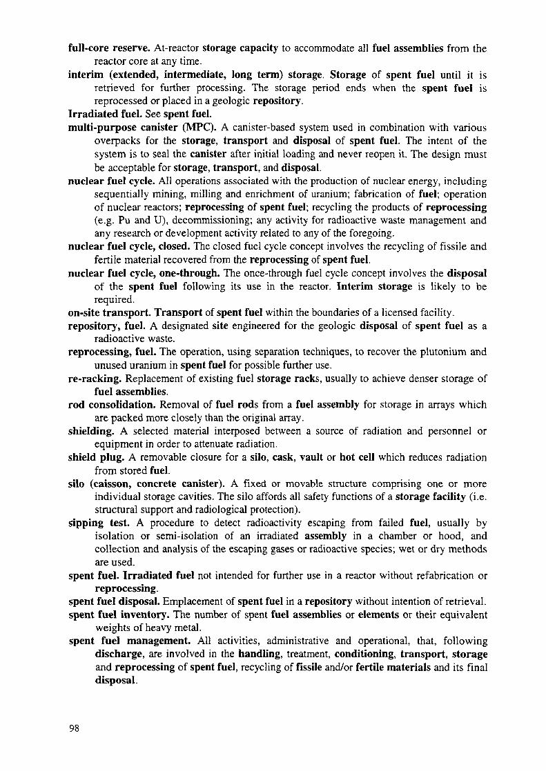
full-core reserve. At-reactor storage capacity to accommodate all fuel assemblies from thereactor core at any time.
interim (extended, intermediate, long term) storage. Storage of spent fuel until it isretrieved for further processing. The storage period ends when the spent fuel isreprocessed or placed in a geologic repository.
Irradiated fuel. See spent fuel,multi-purpose canister (MFC). A canister-based system used in combination with various
overpacks for the storage, transport and disposal of spent fuel. The intent of thesystem is to seal the canister after initial loading and never reopen it. The design mustbe acceptable for storage, transport, and disposal,
nuclear fuel cycle. All operations associated with the production of nuclear energy, includingsequentially mining, milling and enrichment of uranium; fabrication of fuel; operationof nuclear reactors; reprocessing of spent fuel; recycling the products of reprocessing(e.g. Pu and U), decommissioning; any activity for radioactive waste management andany research or development activity related to any of the foregoing.
nuclear fuel cycle, closed. The closed fuel cycle concept involves the recycling of fissile andfertile material recovered from the reprocessing of spent fuel,
nuclear fuel cycle, one-through. The once-through fuel cycle concept involves the disposalof the spent fuel following its use in the reactor. Interim storage is likely to berequired.
on-site transport. Transport of spent fuel within the boundaries of a licensed facility.repository, fuel. A designated site engineered for the geologic disposal of spent fuel as a
radioactive waste.reprocessing, fuel. The operation, using separation techniques, to recover the plutonium and
unused uranium in spent fuel for possible further use.re-racking. Replacement of existing fuel storage racks, usually to achieve denser storage of
fuel assemblies,rod consolidation. Removal of fuel rods from a fuel assembly for storage in arrays which
are packed more closely than the original array.shielding. A selected material interposed between a source of radiation and personnel or
equipment in order to attenuate radiation.shield plug. A removable closure for a silo, cask, vault or hot cell which reduces radiation
from stored fuel,silo (caisson, concrete canister). A fixed or movable structure comprising one or more
individual storage cavities. The silo affords all safety functions of a storage facility (i.e.structural support and radiological protection).
sipping test. A procedure to detect radioactivity escaping from failed fuel, usually byisolation or semi-isolation of an irradiated assembly in a chamber or hood, andcollection and analysis of the escaping gases or radioactive species; wet or dry methodsare used.
spent fuel. Irradiated fuel not intended for further use in a reactor without refabrication orreprocessing.
spent fuel disposal. Emplacement of spent fuel in a repository without intention of retrieval.spent fuel inventory. The number of spent fuel assemblies or elements or their equivalent
weights of heavy metal.spent fuel management. All activities, administrative and operational, that, following
discharge, are involved in the handling, treatment, conditioning, transport, storageand reprocessing of spent fuel, recycling of fissile and/or fertile materials and its finaldisposal.

spent fuel pool (basin, bay, pond). A water-filled facility designed and operated for storing,cooling, maintaining and shielding spent fuel assemblies or rods,
spent fuel storage. The process of emplacement and retention of spent fuel in a safe andretrievable manner. This implies an facility affording adequate environmental andphysical protection. Shielding, containment of radionuclides, criticality control, anddecay heat dissipation must be provided.
storage density. The quantity of spent fuel stored per unit of storage area or volume.storage facility (system). A facility used for the storage of spent fuel and related
components (see spent fuel storage),storage pool. A specially designed spent fuel pool for interim storage and associated
operations.storage rack, fuel. A structure in a wet or dry storage facility that holds spent fuel
assemblies or storage container in a configuration to control criticality, provide heatremoval, facilitate fuel handling, and to prevent seismic damage.
storage temperature. Normally taken to mean the cladding temperature of the fuel. Thetemperature of other components and the environment may be relevant to the conditionof the fuel,
transport. Movement of spent fuel from one licensed facility to another in the public domainusing transport packages under prescribed conditions and regulations, in respect ofwhich there are international guidelines.
transport cask (shipping cask, packaging). A heavy protective container used in thetransport of spent fuel, and which dissipates heat, and provides shielding andcontainment, and prevents criticality. Transport cask could be wet and dry.
vault. An above- or below-ground reinforced concrete structure containing an array of storagecavities, each of which could contain one or more fuel units, shielding is provided bythe exterior of the structure. Heat removal is principally by forced or natural movementof gases over the exterior of the fuel unit or storage cavity. Heat rejection to theatmosphere is either direct or via a secondary cooling system.
NEXT PAGE(S)left BLANK
99

Baillif, L.Brown, G.A.
Buday, G.
Dyck, P.
Einfeld, K.
Frejtich, Z.
Fomenko, A.
Garamszeghy, M.Grigoriev, A.
Kmosena, J.Makarchuk, T.F.Malmstrom, H.Pattantyus, P.
Seetharamaiah, P.
Smith, M.
P. StandringStringer, J.B.
Supko, E.
Szabo, J.Takala, H.
Takats, F.
CONTRIBUTORS TO DRAFTING AND REVIEW
NUSYS, FranceMagnox Electric, United Kingdom
Paks Nuclear Power Plant, Hungary
International Atomic Energy AgencyPrivate consultant, Germany
CEZ, Czech Republic
Energoprojekt Design Institute, Ukraine
Ontario Hydro, CanadaInternational Atomic Energy Agency
Slovenske Elektrarne, Slovakia
VNIPIET, Russian FederationBEZ Ahaus GmbH, Germany
Atomic Energy of Canada Ltd, Canada
BARC, India
Virginia Electric & Power Company, United States of America
BNFL, United KingdomTWR Environmental Safety Systems Inc.,United States of America
Energy Resources International Inc., United States of America
Permanent Mission of Israel, Vienna,Finnish Centre for Radiation & Nuclear Safety, Finland
TS Enercon, Hungary
Consultants Meetings
Vienna, Austria: 22-25 August 1995, 26 February-1 March 1996, 10-14 June 1996,3-7 February 1997, 16-19 December 1997
Advisory Group Meetings
Vienna, Austria: 30 October-3 November 1995, 5-8 November 1996,
101