iaea tecdoc series · spent fuel storage operation — lessons learned @ iaea tecdoc 1725 tecdoc...
TRANSCRIPT

Spent Fuel Storage Operation —
Lessons LearnedIAEA TECD
OC 1725
Spent Fuel StorageOperation — Lessons Learned
@
IAEA TECDOC 1725
TECDOC No. 1725
IAEA TECDOC SERIES

spent fuel storage operation — lessons learned

afgHanistanalBaniaalgeriaangolaargentinaarmeniaaustraliaaustriaaZerBaiJanBaHrainBangladesHBelarusBelgiumBeliZeBeninBoliViaBosnia and HerZegoVinaBotsWanaBraZilBulgariaBurKina fasoBurundicamBodiacamerooncanadacentral african
repuBliccHadcHilecHinacolomBiacongocosta ricacÔte d’iVoirecroatiacuBacypruscZecH repuBlicdemocratic repuBlic
of tHe congodenmarKdominicadominican repuBlicecuadoregyptel salVadoreritreaestoniaetHiopiafiJifinlandfrancegaBongeorgiagermanygHanagreece
guatemalaHaitiHoly seeHondurasHungaryicelandindiaindonesiairan, islamic repuBlic of iraQirelandisraelitalyJamaicaJapanJordanKaZaKHstanKenyaKorea, repuBlic ofKuWaitKyrgyZstanlao people’s democratic
repuBliclatVialeBanonlesotHoliBerialiByaliecHtensteinlitHuanialuXemBourgmadagascarmalaWimalaysiamalimaltamarsHall islandsmauritaniamauritiusmeXicomonacomongoliamontenegromoroccomoZamBiQuemyanmarnamiBianepalnetHerlandsneW ZealandnicaraguanigernigerianorWayomanpaKistanpalau
panamapapua neW guineaparaguayperupHilippinespolandportugalQatarrepuBlic of moldoVaromaniarussian federationrWandasaudi araBiasenegalserBiaseycHellessierra leonesingaporesloVaKiasloVeniasoutH africaspainsri lanKasudansWaZilandsWedensWitZerlandsyrian araB repuBlictaJiKistantHailandtHe former yugoslaV
repuBlic of macedoniatogotrinidad and toBagotunisiaturKeyugandauKraineunited araB emiratesunited Kingdom of
great Britain and nortHern ireland
united repuBlicof tanZania
united states of americauruguayuZBeKistanVeneZuelaVietnamyemenZamBiaZimBaBWe
the following states are members of the international atomic energy agency:
the agency’s statute was approved on 23 october 1956 by the conference on the statute of the iaea held at united nations Headquarters, new york; it entered into force on 29 July 1957. the Headquarters of the agency are situated in Vienna. its principal objective is “to accelerate and enlarge the contribution of atomic energy to peace, health and prosperity throughout the world’’.

iaea-tecdoc-1725
spent fuel storage operation — lessons learned
international atomic energy agencyVienna, 2013

CoPYrIGHt notICe
all iaea scientific and technical publications are protected by the terms of the universal copyright convention as adopted in 1952 (Berne) and as revised in 1972 (paris). the copyright has since been extended by the World intellectual property organization (geneva) to include electronic and virtual intellectual property. permission to use whole or parts of texts contained in iaea publications in printed or electronic form must be obtained and is usually subject to royalty agreements. proposals for non-commercial reproductions and translations are welcomed and considered on a case-by-case basis. enquiries should be addressed to the iaea publishing section at:
marketing and sales unit, publishing sectioninternational atomic energy agencyVienna international centrepo Box 1001400 Vienna, austriafax: +43 1 2600 29302tel.: +43 1 2600 22417email: [email protected] http://www.iaea.org/books
for further information on this publication, please contact:
nuclear fuel cycle and materials sectioninternational atomic energy agency
Vienna international centrepo Box 100
1400 Vienna, austriaemail: [email protected]
© iaea, 2013printed by the iaea in austria
december 2013
iaea library cataloguing in publication data
spent fuel storage operation : lessons learned. – Vienna : international atomic energy agency, 2013. p. ; 30 cm. – (iaea-tecdoc series, issn 1011-4289 ; no. 1725) isBn 978-92-0-113813-2 includes bibliographical references.
1. spent reactor fuels – storage. 2. spent reactor fuels – safety measures. 3. nuclear fuels – management. i. international atomic energy agency. ii. series.
iaeal 13-00855

FOREWORD
Experience gained in planning, constructing, licensing, operating, managing and modifying spent fuel storage facilities in some Member States now exceeds 50 years. Continual improvement is only achieved through post-project review and ongoing evaluation of operations and processes. This publication is aimed at collating and sharing lessons learned. Hopefully, the information provided will assist Member States that already have a developed storage capability and also those considering development of a spent nuclear fuel storage capability in making informed decisions when managing their spent nuclear fuel. This publication is expected to complement the ongoing Coordinated Research Project on Spent Fuel Performance Assessment and Research (SPAR-III); the scope of which prioritizes facility operational practices in lieu of fuel and structural components behaviour over extended durations. The origins of the current publication stem from a consultants meeting held on 10–12 December 2007 in Vienna, with three participants from the IAEA, Slovenia and USA, where an initial questionnaire on spent fuel storage was formulated (Annex I). The resultant questionnaire was circulated to participants of a technical meeting, Spent Fuel Storage Operations — Lessons Learned. The technical meeting was held in Vienna on 13–16 October 2008, and sixteen participants from ten countries attended. A consultants meeting took place on 18–20 May 2009 in Vienna, with five participants from the IAEA, Slovenia, UK and USA. The participants reviewed the completed questionnaires and produced an initial draft of this publication. A third consultants meeting took place on 9–11 March 2010, which six participants from Canada, Hungary, IAEA, Slovenia and the USA attended. The meeting formulated a second questionnaire (Annex II) as a mechanism for gaining further input for this publication. A final consultants meeting was arranged on 20–22 June 2011 in Vienna. Six participants from Hungary, IAEA, Japan, UK and USA attended the meeting. The responses to the second questionnaire, which was circulated at the International Conference on Management of Spent Fuel from Nuclear Power Reactor (2010), were reviewed at this meeting. Discussions on what was initially learned from the accident at Fukushima also took place. In response to the accident, an additional chapter (Chapter 4) has been added to detail the lessons learned from the remediation of severely damaged fuel at Three Mile Island unit 2 and at Paks. The IAEA gratefully acknowledges the contributions of the technical meeting participants, the Member States that responded to the questionnaires, and the individuals who participated in the drafting and review of this publication. The IAEA officers responsible for this publication were Z. Lovasic, X. Zou and P. Standring of the Division of Nuclear Fuel Cycle and Waste Technology.

EDITORIAL NOTE
This publication has been prepared from the original material as submitted by the authors. The views expressed do not necessarily reflect those of the IAEA, the governments of the nominating Member States or the nominating organizations.
This publication has not been edited by the editorial staff of the IAEA. It does not address questions of responsibility, legal or otherwise, for acts or omissions on the part of any person.
The use of particular designations of countries or territories does not imply any judgement by the publisher, the IAEA, as to the legal status of such countries or territories, of their authorities and institutions or of the delimitation of their boundaries.
The mention of names of specific companies or products (whether or not indicated as registered) does not imply any intention to infringe proprietary rights, nor should it be construed as an endorsement or recommendation on the part of the IAEA.
The authors are responsible for having obtained the necessary permission for the IAEA to reproduce, translate or use material from sources already protected by copyrights.
The IAEA has no responsibility for the persistence or accuracy of URLs for external or third party Internet web sites referred to in this book and does not guarantee that any content on such web sites is, or will remain, accurate or appropriate.

CONTENTS 1. INTRODUCTION AND OBJECTIVES ................................................................................. 1
2. WET STORAGE FACILITIES ............................................................................................... 2
2.1. PLANNING ....................................................................................................................... 2
2.2. NEW FACILITIES ............................................................................................................ 3
2.3. WET STORAGE OPERATIONS ..................................................................................... 6
2.3.1. Transport cask operations ........................................................................................... 6
2.3.2. Loading spent fuel into storage racks or containers ................................................... 9
2.3.3. Storage chemistry ..................................................................................................... 10
2.3.4. Control of pool water contaminants ......................................................................... 16
2.3.5. Spent fuel pool cooling ............................................................................................ 21
2.3.6. Ventilation ................................................................................................................ 22
2.3.7. Visibility ................................................................................................................... 22
2.3.8. Surveillance and monitoring .................................................................................... 23
2.3.9. Outdoor storage pools .............................................................................................. 26
2.3.10. Ad-hoc operations ................................................................................................. 26
2.4. SPENT FUEL PERFORMANCE ................................................................................... 27
2.4.1. General performance ................................................................................................ 27
2.5. FACILITY MODIFICATIONS ...................................................................................... 29
2.5.1. Fuel handling systems .............................................................................................. 30
2.5.2. Storage capacity enhancements ................................................................................ 31
2.5.3. Licensing burnup credit ............................................................................................ 35
2.5.4. Change to AR fuel route ........................................................................................... 36
2.6. MAINTENANCE ............................................................................................................ 36
2.6.1. Pool liner .................................................................................................................. 36
2.6.2. Control systems/impact of technology ..................................................................... 37
2.6.3. Degradation of facility components ......................................................................... 38
2.6.4. Spent fuel repairs ...................................................................................................... 39
2.7. TRANSFER FROM WET STORAGE TO NEXT FUEL MANAGEMENT PHASE (SPENT FUEL RETRIEVAL) ................................................................................................... 41
3. DRY STORAGE FACILITIES .............................................................................................. 45
3.1. PLANNING ..................................................................................................................... 45
3.2. NEW FACILITIES .......................................................................................................... 50
3.2.1. Construction/design .................................................................................................. 51

3.2.2. Licensing of casks/facilities for dry storage ............................................................. 51
3.2.3. Manufacturing .......................................................................................................... 53
3.3. DRY STORAGE OPERATIONS ................................................................................... 53
3.3.1. Selection of fuel ....................................................................................................... 53
3.3.2. Preparations prior to storage or transfer cask loading (wet loading) ....................... 54
3.3.3. Loading spent fuel into canisters/casks/storage tubes .............................................. 56
3.3.4. Processing for storage .............................................................................................. 57
3.3.5. Surveillance and monitoring in storage .................................................................... 59
3.4. SPENT FUEL PERFORMANCE IN DRY STORAGE ................................................. 60
3.5. MAINTENANCE ............................................................................................................ 63
3.5.1. Modifications to existing systems/designs ............................................................... 63
3.5.2. Re-licensing of storage casks ................................................................................... 63
3.6. TRANSFER FROM DRY STORAGE TO NEXT MANAGEMENT PAHSE .............. 63
4. LESSONS LEARNT MANAGEMENT OF SEVERELY DAMAGED SPENT NUCLEAR FUEL .............................................................................................................................................. 64
REFERENCES ............................................................................................................................... 67
LIST OF ABBREVIATIONS ........................................................................................................ 69
ANNEX I Questionaires Distributed to MEMBER States ............................................................ 71
ANNEX II 2nd Questionnaire on Spent Fuel Storage .................................................................. 76
CONTRIBUTORS TO DRAFTING AND REVIEW ................................................................... 79

1
1. INTRODUCTION AND OBJECTIVES
Spent fuel storage is an interim step in the back end of the nuclear fuel cycle which facilitates spent fuel reprocessing and recycling of products or direct disposal. To date the direct disposal of fuel has not been exercised, but there are a number of projects which are in an advanced stage of meeting this goal. The general trend, however, has been to ever increasing dwell times in storage and durations in excess of 100 years are now being envisaged. The current position is far removed from early lifecycle plans which were mostly based on reprocessing spent fuel in the short term. At-reactor (AR) storage was, therefore, based upon short dwell times of <5 years and in some cases is limited to 1–2 years storage capacity.
Reactor new builds are now based upon a minimum of 60 years storage and some are incorporating the ability for expansion. Current spent fuel storage designs have come a long way from those on the drawing board back in the late 1940s and incorporate previous learning and the requirements of national and international safety standards which have been progressively introduced.
The recent incident at Fukushima has seen a review of the robustness of spent fuel storage and its ability to respond to beyond design base accident scenarios. This may see further iterations to key safety features such as cooling supplies.
Over the past 20–30 years the role played by dry storage systems in filling the gap between available AR storage and the availability of back end services has increased and now represents around 20% of all stored fuel. The main attractions of dry storage are its passive cooling capability and reduced up-front costs through the ability to add incremental capacity.
With ever increasing storage durations the challenge for older storage systems is the ability to demonstrate that they are still fit-for-purpose; i.e. demonstrating that the storage system meets the latest regulations. To date redundancy in design has helped many operators meet these challenges. To ensure continued operation it is critical to have in-place robust ageing management plans. This subject is dealt with in some detail in [1].
The main objective of this technical document is to create a resource for Member States engaged in managing spent power reactor fuel highlighting practices to emulate and situations to avoid. Whilst the document does include a section on spent fuel performance, for a detailed account of the degradation mechanisms which can affect different fuel types in wet and dry storage the reader is referred to the TECDOCs [2–6] produced from the IAEAs Coordinated Research Projects: Behaviour of Spent Fuel Assemblies in Storage (BEFAST, 1981 to 1995) and Spent Fuel Performance Assessment and Research (SPAR, 1997 to date).

2
2. WET STORAGE FACILITIES
Wet storage is by far the most common form of spent fuel storage over 80% of the world’s spent fuel resides in wet storage. This is not surprising because most large commercial plants have light (or heavy) water reactors in which the fuel is designed to dwell in water for long periods without deterioration and which provides the necessary cooling after discharge.
Although pool storage is a mature technology the latest storage pools have come through an evolutionary process and incorporate the learning from 50+ years of operating experience; discussed in Section 2.2.
The following figures (Figs 1–2) help to demonstrate the difference between at-reactor (AR) (Fig. 1) and away-from-reactor (AFR) facilities (Fig. 2). The tendency being for centralised wet AFR storage facilities to accommodate >1000 t·HM whilst <100 t·HM could only be accommodated at older AR facilities, spacing between storage modules is usually larger (to facilitate routine placement and retrieval of fuel), and fuel handling operations are undertaken by remotely operated fuel handling machines.
Note the difference between Russian origin pool design c.f. western counterparts in having plates covering the storage pools to prevent evaporation and possible spread of air-borne contamination.
2.1. PLANNING
The most important messages for any spent fuel owner or storage facility operator are to plan early and to engage key stakeholders at the start of the project. Stakeholders should be involved in the whole process so that they are actively involved in the decision making processes and have been given the opportunity to influence the final decision. It is worth visiting [7] to gain further information on engagement in relation to spent fuel management.
Local governments will look to regulators (both nuclear and environmental) to support the process. Regulators will be looking to see how the national and international safety requirements will be met in the proposal; i.e. the guidance as given [8]. Lifetime plans also need to include support services for new storage facilities and take account of any services that will be decommissioned during the project lifetime; for example replacement of services provided by the nuclear power plant (NPP) if storage is projected to go beyond NPP life.
More recently greater attention has been paid to environmental impact statements. The latest methodology may look to the operator to demonstrate that the chosen technology or continued operation of existing
LWR CANDU WWER LWR/AGR FIG. 1. Examples of AR wet storage facilities. FIG. 2. Examples of AFR wet storage facilities.

3
facilities is best available technology for the particular application. In some Member States the application may also need to show how principles such as the waste hierarchy will be met.
Table 1 provides a summary of the lessons learned relating to planning.
2.2. NEW FACILITIES
The IAEA has produced a number of guidance documents which assist the designer in identifying the features and systems which need to be incorporated into the plant design to ensure that international safety standards and principles are met. These include:
Design of Fuel Handling and Storage System in Nuclear Power Plants, IAEA-NS-G-1.4, 08 August 2003;
Storage of Spent Nuclear Fuel, IAEA-SSG-15, 27 March 2012; Storage of Radioactive Waste, IAEA-WS-G-6.1, 28 November 2006.
Further information on the process for establishing a new storage facility is given in Section 4.2.
Over the past 50 years the storage pool has evolved from an outdoor single skinned pool built to national standard, but not an agreed international standard; for example Fig. 3. The latest pools are built to the latest standards and incorporate design feature to minimise the dose uptake to operators, have passive cooling and security features in the event of either system failure or intervention; as shown in Fig. 4.
TABLE 1. LESSONS LEARNED PLANNING
Issue Problem Resolution
Original design assumption invalidated by a change in government policy.
Reprocessing ‘Moratorium’ in some countries has impacted on the original storage expectation.
New builds should incorporate the flexibility for expansion.
A change in lifetime plan as a result of government intervention should be recognised in the storage operator/NPP risk register. Mitigation is through having contingency plans in-place that is routinely reviewed. Such plans would have triggers to provide additional storage capacity.
Change of use and/or new operating licence required.
Original operating licence or planning consent based on interim storage in support of reprocessing activities.
Change of use application to local authority
New lifetime plan justified and new safety case produced to cover new operating regime.

4
FIG. 3. Outdoor Storage Pool. FIG. 4. Construction of advanced pool Passive heat exchangers can be seen on the side of the pool walls.
Table 2 provides examples of the safety related design improvements that have been incorporated into storage facilities since first operation; see IAEA-NS-G-1.4 and IAEA-SSG-15.
TABLE 2. EXAMPLES OF SAFETY RELATED DESIGN IMPROVEMENTS WHICH HAVE BEEN INCORPORATED INTO STORAGE POOLS SINCE FIRST OPERATIONS Design change Improvement Protection of the pool water wind water line with stainless steel.
Prevents the erosion of concrete through wet dry cyclic process and avoids the adsorption of activity making decontamination easier.
Radiation resistant polymer coatings (unlined pools).
Early paint systems were prone to degradation under radiation and storage conditions.
Prevents coating peeling and becoming a waste issue.
Reduces/prevents activity adsorption into the concrete structure.
Roofing storage pools. Prevents the ingress of air-borne particulates and contaminants.
Spread of contamination.
Exclusion of wildlife.
Seismic qualification. Alignment to international safety standards.
Secondary containment systems (pool within a pool).
Prevents seepage of pool water to ground or building structure forms a secondary containment barrier in the event of a catastrophic failure to the primary pool structure.

5
TABLE 2. DESIGN IMPROVEMENTS WHICH HAVE BEEN INCORPORATED INTO STORAGE POOLS WITH OPERATING EXPERIENCE (cont.) Design change Improvement Stainless steel lining of complete pool or operational areas of the pool.
Prevents the spread of contamination. Reduces decommissioning requirements.
Minimises pool water seepage from the pool.
The later systems have detection systems between the stainless steel liner and the concrete pool structure.
Secure radio controlled building crane system with motorised ram’s horns.
Original building cranes were fixed and the ram’s horns were not motorised; requiring the use of ropes to turn transfer or transport casks.
Radio controlled system allows the crane driver to move with the transport package. Improving all around awareness of where the package is.
Design and software interlocks on building crane and fuel handling machines.
Prevents suspended loads being moved over fuel and or fuel handling machines and vice a versa.
Wetted components fabricated from stainless steel.
Many of the original wetted components used in lifting beams, storage racks, and tools were fabricated out of painted mild steel. The durability of these components was subject to the quality of the coatings used. The coatings absorb activity and become a dose issue with time if not decontaminated. Secondly where the coating degrades corrosion of the base metal can occur which also acts to attract activity leading to dose uptake issue to operators.
Stainless steel counterparts tend to only result in surface contamination which is relatively easily removed.
Structure designed to retain boiling water. Prevent catastrophic failure of the pool structure due to thermal expansion (loss of cooling fault scenario).
Passive cooling system. Removes reliance on active cooling systems. Responds to passive safety requirement.
Strengthening and duplication of systems. Resistance to aircraft impact, natural events, redundancy in the event of loss of services.

6
A number of Member States have also emphasised the importance of being minded at the fuel facility design stage to minimising the handling of fuel to ensure that unnecessary fuel handling steps are avoided.
2.3. WET STORAGE OPERATIONS
Spent fuel storage operations begin with the receipt of spent fuel either transferred from the reactor core or from a transport cask.
2.3.1. Transport cask operations
For most wet storage facilities this involves the receipt of the transport cask into a wet receipt pool or unloading bay; there are a few exceptions; examples include Fuel Handling Plant and the First Generation AGR Storage Pond at Sellafield (UK), and T(0) facility at Cap la Hague (France) which all have dry receipt and cask handling facilities.
A variation to the above is dry cask handling with wet loading which is practiced at some French nuclear power plants (NPPs).
Good practices include:
• Conditions for acceptance; o Fuel consignor is provided with clear guidance on what is acceptable in terms of fuel
types approved in the plant safety case, condition of the fuel, etc. • Provision of fuel records (design and manufacturing data); • Authorization for fuel transfer;
o Fuel data is checked against the conditions for acceptance by plant support operators and formal approval is given for the fuel to be received.
• Witnessing of fuel loading (particularly relevant to fuel loaded to a containerized system); • Quality Plan for the transport package;
o Document relating to each cask movement stating contents (fuel, frame or canister, settings, cask condition etc.).
• Transport cask dwell time in the receipt pool or unloading pit is minimized; • Protecting areas of the transport cask where contamination may accumulate.
Table 3 lists the lessons learned in relation to transport cask operations.

7
TABLE 3. LESSONS LEARNED TRANSPORT CASK OPERATIONS
Issue Problem Resolution
External Contamination (wet transportation casks).
Sweating of contamination from the transport cask paint system.
Transport cask returned for further decontamination.
Minimize dwell time in pool receipt bay or cask unloading pit.
Purge the receipt pool or unloading pit with clean water in the vicinity of the cask during unloading operations.
External Contamination (all types).
Contamination hold-up in transport cask orifices leaches onto cask body during subsequent handling and transportation operations.
Joints and bolt holes should be covered in protective tape to minimize contamination ingress.
External Contamination (dry types).
Adsorption of activity onto fins and neutron absorber material.
Standard practice is to protect areas such as fins and exposed neutron absorber material (which are difficult to decontaminate) with a protective jacket and water purged through the jacket during in pool handling operations.
Transport cask suspended by a single lifting trunion.
Lifting beam incorrectly engaged/Operator error.
Temporary restraints fitted to ensure cask drop does not occur during lowering operations.
Review operator training.
Area gamma alarms activated and interlocks activated.
Loose contamination released from inside transport cask during unloading operations.
Recovery through health physics and management control.
Consignor informed of problem.

8
TABLE 3. LESSONS LEARNED TRANSPORT CASK OPERATIONS (cont.) Issue Problem Resolution
Storage Pool or Cask Loading Pit water cleanliness.
Particulates trapped between seal and seal face – leak tightness criteria not met.
Chemical residues/particulates have the potential to initiate corrosion of seals/seal face which will lead to seal failure.
Check pool/pit water quality prior to committing cask.
Purge any chemical contaminates from the pool/pit water or add clean-up system.
Check filters are working efficiently.
Introduce a clean water supply local to the cask to form a water curtain.
Introducing contaminants into the storage pool/loading pit.
Storage/transfer cask surfaces have become contaminated either as residues of the manufacturing process or through interim storage (usually whilst parked outside the storage building or NPP).
Cask procurement contract should state the levels of surface contamination of the finished product. Surface contamination should be checked on receipt and the cask cleaned if necessary.
Clean transfer/storage cask surfaces prior to committing to the storage pool/loading pit.
Cross contamination. Surfaces of the storage cask become contaminated (radiological and non- radiological).
Put a protective shroud or skirt around the cask.
Mixing effects. Syphoning of water into internal cask voids. Potential for loose contamination to be spread.
The effect can be minimised by filling the voids with clean water prior to committing to pool/loading pit.
Pool/Loading pit water compatibility.
Reaction between the materials or coatings used in the fuel canister, cask or tools and the pool or loading pit water. For example boric acid has reacted with the zinc coating on fuel canisters; where the concentration was high.
Check materials compatibility with pool/loading pit water bounding conditions.

9
2.3.2. Loading spent fuel into storage racks or containers
Spent fuel handling operations in their simplest form involve a fuel handling tool, a hoist, travelling bridge, binoculars and an operator. The reliance is placed on operator judgement to engage the fuel handling tool, move the fuel (whilst still maintaining enough shielding and avoiding collision with objects) and the ability to read Fuel assembly numbers. Up to date fuel handling systems can be operated remotely, have interlocks to prevent collisions etc. and closed circuit television units to aid handling tool engagement and fuel assembly number recognition.
Given the thousands of tonnes of spent fuel that has been handled the number of fuel drops or incidents associated with loading spent fuel into storage racks or containers is limited. Where they have occurred this is usually as a result of operator error. Errors are often attributed to poor ergonomics of handling equipment (e.g., illegible displays), faulty or incomplete procedures, or mechanical wear of the handling equipment.
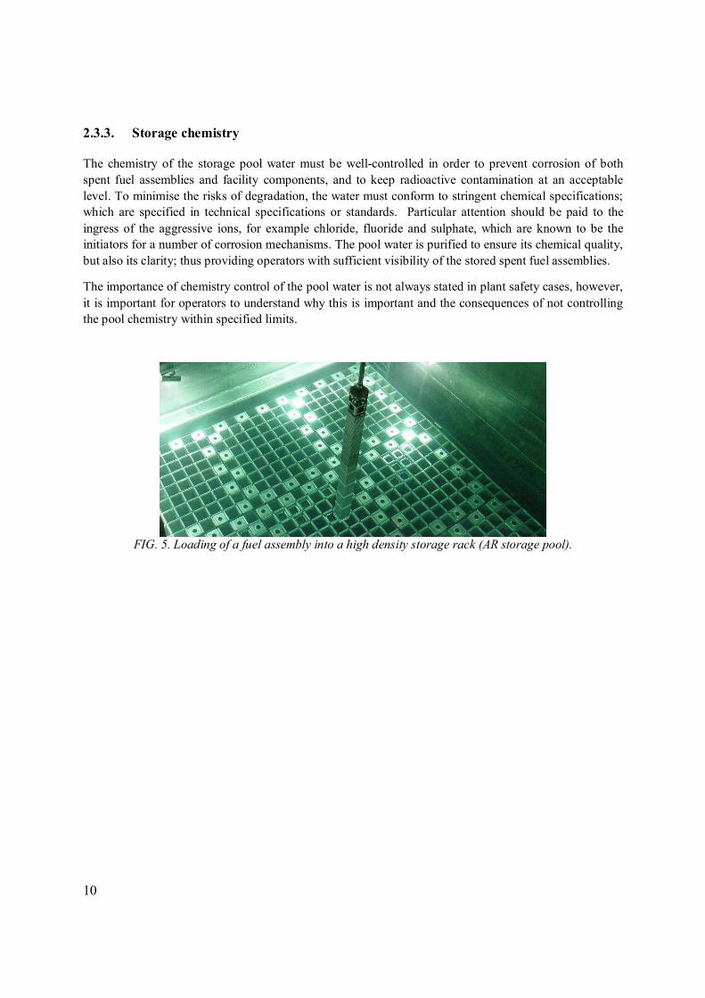
The nuclear safety guide [9] provides guidance on the handling of spent fuel. Fig. 5 shows a fuel assembly being loaded into a storage rack.
Operating experience has led to the development of a number of ‘Good practices’ during fuel handling and the identification of conditions/tools to avoid fuel/fuel container drops. These include:
• Operator training; • Use of a quality-assured step-by-step programme; • Good lighting; • Control of pool water visibility; • Up to date records of fuel assembly locations; • Fuel assembly unique identifiers that are clearly marked in a place on the assembly that can be
easily read/recorded by the operators; • Use of closed circuit television cameras to ensure handling grabs are engaged and for reading
unique fuel assembly identity; • Design of grabs that ensure positive locking; i.e. fail safe; • Checking equipment prior to use; • Supervision during fuel handling operations (four-eye principle); • Computer aided systems; • Any alteration to the Fuel assembly are adequately recorded and reported to fuel handling team
prior to fuel movements.
When human performance or equipment performance issues arise, corrective actions are implemented to eliminate the potential for reoccurrence. This is accomplished by revising procedures, modifying equipment or other means. International operational experience is reported through the IAEA’s incident reporting system (IRS); to members. The IAEA has recently produced an incident reporting system (IRS) topical study on ‘Events Connected to Fuel Handling’ [10]. Table 4 provides a summary of the lessons learned relating to loading spent fuel into storage racks or containers.
10
2.3.3. Storage chemistry
The chemistry of the storage pool water must be well-controlled in order to prevent corrosion of both spent fuel assemblies and facility components, and to keep radioactive contamination at an acceptable level. To minimise the risks of degradation, the water must conform to stringent chemical specifications; which are specified in technical specifications or standards. Particular attention should be paid to the ingress of the aggressive ions, for example chloride, fluoride and sulphate, which are known to be the initiators for a number of corrosion mechanisms. The pool water is purified to ensure its chemical quality, but also its clarity; thus providing operators with sufficient visibility of the stored spent fuel assemblies.
The importance of chemistry control of the pool water is not always stated in plant safety cases, however, it is important for operators to understand why this is important and the consequences of not controlling the pool chemistry within specified limits.
FIG. 5. Loading of a fuel assembly into a high density storage rack (AR storage pool).

11
TABLE 4. LESSONS LEARNED LOADING SPENT FUEL INTO STORAGE RACKS OR CONTAINERS
Issue Problem Resolution
Unexpected behaviour of spent fuel.
Older designs of BWR fuel allowed for some movement (twisting) during fuel handling which can give the appearance of the fuelled section rotating around the handling feature.
Operator training.
Cannot read the fuel assembly identifier this leads to delays in production activities.
The size and location of unique fuel identifiers can be in places where viewing is restricted or the Fuel assembly has become covered in debris/crud.
May require the fuel assembly to be cleaned and deploying mobile CCTV local to the fuel handling feature.
The problem is mainly associated with older fuel as fuel manufacturers have improved identifier markings over the years.
Missing fuel rod or unexpected damage to fuel assembly.
Up-to-date information on fuel assembly condition not recorded or record is not been lodged on the fuel assembly data management system in-place.
Lifetime records for fuel assemblies needs to incorporate a formal mechanism for reporting non-conformances.
Fuel assembly dropped. Fuel handling tool not properly engaged.
See list of error traps given above.
See ‘Good practices’ given above.
Storage module dropped. Failure to engage all four lifting points on the storage module.
Lifting tool modified to include visual indicator that all four lifting points are engaged.
Increased friction experienced during the loading of fuel assembly into storage rack.
Increased burn-up of fuel caused some deformation of fuel assembly.
Limited to certain fuel manufacturers. The cause was not analysed but problem solved in next batches of fuel.

12
TABLE 4. LESSONS LEARNED LOADING SPENT FUEL INTO STORAGE RACKS OR CONTAINERS (cont.)
Issue Problem Resolution
Potential for fuel to ground on storage rack.
Some spacer designs are prone to damage during fuel handling.
The storage tube design of higher density racks can require much more operator involvement and experience when loading the FA into racks.
Fuel manufacturing issue, requires design modification to the spacer.
Operator training.
IAEA seals broken without informing IAEA by operators.
Operator error.
Can also be related to production pressure versus safeguard inspector availability (e.g. where operation is being carried-out on a night shift).
Operator training.
Improve production planning/notification of inspectors.
Miss loading of a fuel storage rack
(Burnup Credit).
Operator error.
Certain storage rack positions within the spent fuel pool may be blocked by administrative means only. Poor administrative control may lead to a violation of the plant safety case.
Operator training/improve administrative control/use of zoning markers.
Fuel handling machine keeps tripping (plant operability issue.)
Safety features incorporated into fuel handling machines (e.g. travel interlocks, over-raise etc.) as they become worn trip to safe mode and impact on plant production.
May call for major maintenance to realign masts etc.
Machines can be operated in maintenance mode subject to operator supervision.
The water chemistry and radioactivity of the spent fuel pool water is controlled by regular analysis and measurements. The frequency of analysis and range of species analysed for tend to be fuel and operator specific; in some case these are dictated by regulatory requirements. Table 5 gives an example of the parameters analysed and frequency for an AFR demineralised water spent fuel storage facility.

13
TABLE 5. EXAMPLE OF TYPICAL VALUES FOR SELECTED PARAMETERS IN AFR DEMINERALISED WATER STORAGE FACILITY AND FREQUENCY OF MONITORING
Parameter Typical Frequency of analysis
pH 6-7 3×/week
Conductivity <0.7 µS/cm 3×/week
Chloride 0.04 mg/L On-line & 3×/week
Sulphate 0.1 mg/L Weekly
Fluoride 0.1mg/L Weekly
Sodium 0.1 mg/L Monthly
Phosphate 0.04 mg/L Monthly
Nitrate 0.1 mg/L Monthly
Total β <10 Bq/ml 3×/week
Total α <0.1 Bq/ml 3×/week
137Cs <7 Bq/ml 3×/week
134Cs <1 Bq/ml 3×/week
60Co <1 Bq/ml 3×/week
54Mn <0.1 Bq/ml 3×/week
Some of the Good Practices highlighted in questionnaire response were:
• Sampling of supplies before use in the storage pool; • On-line monitoring; • Development of trigger levels (for investigation) and action levels (to take remedial action).
Table 6 provides a summary of the lessons learned relating to spent pool chemistry.

14
TABLE 6. LESSONS LEARNED POOL CHEMISTRY
Issue Problem Resolution
Chemical excursion. Significant deviation from the recommended guidelines for the control of aggressive ions such as chloride, fluoride and sulphate.
Susceptible fuel assemblies should be inspected for evidence of corrosion and cracking.
pH excursion. Ingress of coolant gas from rector system (Gas reactors) adjusts pool chemistry pH.
Excursion usually picked up quickly and the pH of the pool water adjusted to within normal operating margins.
Assess impact to stored fuel, clean-up systems and wetted components.
Caesium excursion. Indicator that failed fuel is present.
Review pool water analysis to establish when the leaking fuel assembly was committed to storage/confirm fuel assembly is leaking through sipping or liquor sampling.
Isolate leaking fuel assembly in a can or similar containment device.
Reprocessing leaking fuel assembly.
Chemical analysis out of specification or new species picked-up.
Washing of decontaminate agents into storage pool or cask loading/unloading pit.
Brief operators and managers of why pool chemistry is controlled within specified limits and potential impacts of introducing chemicals into the system.
Purge pool water/use clean-up system to remove.
Assess impact to stored fuel, clean-up systems and wetted components.

15
TABLE 6. LESSONS LEARNED POOL CHEMISTRY (cont.)
Issue Problem Resolution
Biological growth in storage pool.
Spent fuel handling operations hampered by visibility issues.
Cosmetic appearance/acceptance by Stakeholders.
The growth of biological species relies upon the presence of phosphate, nitrate, carbon and light. Removal of one or more of these agents should prevent or minimize growth.
Can call for all the fuel to be removed and the facility to be sterilized to remove the problem entirely.
Some of techniques that have been used to kill or minimize biological growth:
• Biocides (these need to be checked as they can contain high levels of aggressive ions such as chloride which would attack the fuel);
• UV light; • Use of ultrasonic probes; • The application of dyes
which block certain wavelengths of light.
Pool dosing chemical out of specification.
Change of chemical supplier failure to control chemical specification.
All changes of suppliers or specifications of chemicals supplied should be reviewed by fuel storage expert as a minimum.
Dilution of soluble neutron absorber.
Potential to impact sub criticality.
The inadvertent feeding of demineralised water into the borated pool water.
Use of appropriate locking devices and systems engineering design.

16
2.3.4. Control of pool water contaminants
It is important to control pool water conatminants for a number of reasons. The ingress of aggressive or corrosive ions can impact on spent fuel and storage component integry (see Section 2.4). Biological species and their associated nutrient sources can impact on pool operability; as visibility can be impaired. In the case where there is elevated activity levels, adsorption of species such as caesium onto metals and corrosion products adhering to the fuel, this can have the following knock-on effects on plant operations:
• Need to control working times within the facility; • Issues associated with activity transfer;
o Impact on maintenance operations of tools and equipment that come into contact with the pool water.
o To downstream plants and transfer casks. • Need to employ additional pool clean-up. This has both a volume of waste and cost implications; • Potential longer term issues associated with post operation clean out and decommissioning.
To minimise pool contamination from leaking fuel, spent fuel identified as leaking either through evaluation of in-core coolant activity or sipping of individual fuel assemblies on discharge, are normally placed into some form of sealed over-pack; for example a welded can. The methods and procedures for identifying leaking fuel in-core and on reactor discharge are described in detail in [11]. In the case AFR storage facilities operators have developed systems for checking the fuel integrity upon receipt. Examples include krypton analysis, transport cask or receipt pool liquor sampling or through detailed fuel inspections (see Section 2.3.7).
2.3.4.1. Ingress of particulates
The ingress of particulates into the bulk pool water can arise from a number of sources and can be the source of aggressive or corrosive ions. The accumulation of particles in the storage pool can arise from:
• Debris brought in on fuel transfer casks; • Through the building ventilation system; • Air-borne material (in the case of outdoor pools); • New storage equipment;
• Materials dropped into the pool by accident or by birds (in the case of outdoor pools);
• In pool maintenance operations (including clean-up systems);
• Corrosion products or ‘CRUD’ adhering to the fuel assemblies which becomes detached during fuel transfer operations (see Section 2.3.3.2).
Table 7 provides a summary of the lessons learned relating to the ingress of particulates.

17
TABLE 7. LESSONS LEARNED INGRESS OF PARTICULATES
Issue Problem Resolution
Build-up of particulates in the cask receipt pool.
Casks not cleaned prior to immersion in the spent fuel storage facility cask receipt pool.
Casks either parked outside the spent fuel storage facility or during transit can pick-up particulates on their external surfaces which are washed off during cask unloading operations. For facilities which handle large volumes of cask receipts this results in a build-up of particulates with time.
Concern can also be raised that the particulates may also be a source of aggressive ion ingress, e.g. chloride, into the storage pool.
A hot water wash prior to cask handling has been reported to help reduce/remove this issue.
General debris floating on the pool surface or materials dropped into the pool.
Operator error, tools and materials in pockets, packaging from plant spares or operating consumables are inadvertently dropped into the storage pool or cask receipt pool or pit.
Establishing foreign materials exclusion policies.
Marking or zoning of plant areas where there is a high risk of materials being dropped into the storage pool/cask receipt pool or pit.
Build-up of materials in outdoor pools.
Passing birds drop material into the storage pool.
Materials are blown into the storage pool.
The incorporation of pool covers will reduce the issue. Pool covers, however, can impact on plant operability.
Maintenance operations during reactor outage lead to fuel assemblies being contaminated to the point they could not be put back into the core.
Insufficient protection measures during maintenance operations.
Plant modification proposal should include an HAZOP and work safety plan; which evaluate all likely events.
The inclusion of wild cards can assist in identifying fault scenarios which may be over-looked by operators.

18
2.3.4.2. CRUD migration
CRUD1 formation, dispostion and subsequent migration is a function of reactor coolant chemistry, reactor design and components utilised in the cooling circuit; water cooled reactors only. CRUD composition varies between PWR and BWR type designs. The former generally results in CRUD composed of nickel spinnel complexes which are tightly bound to the fuel assembly whereas the CRUD found in BWR reactor systems and on BWR fuel assemblies are iron oxide based and tend to be loosely bound to the fuel assemblies.
The main problem with CRUD migration in reactor cooling ciruits, spent fuel transport casks and spent fuel storage operations is dose uptake to operators and maintainence staff from the short lived hard beta 60Co isotope associated with it. The scale of the problem in the 1970s and 1980s led to an analysis of core coolant chemistry to combat the problem; mainly through the removal of impurities in cooling water makeup.
At the time the problem was considered significant enough, by one major spent fuel management service provider, to warrant the introduction of a containerised transport and storage system [6]; commonly known as the multi-element bottle (MEB).
The introduction of the MEBs afforded a number of other advantages [6].
In terms of fuel handling operations the introduction of the MEB led to a significant reduction in operator dose uptake on two fronts: Prevention of crud migrating to the pool, and notably the pool surface, during flask unloading; a significant reduction in working times as the flask pay-load was moved in a single operation. They also led to a reduction in flask external radiation from preventing a build-up of crud between the cask body and the internal lead liner.
Although current spent fuel is considerably cleaner than it‘s predecessors the issue still remains in terms of new fuel discharges (the extent of the problem depends on cooling circuit management) and still needs to be considered for handling of older fuels. Note the short halflife of the 60Co isotope (5.27 years) has significantly reduced the dose aspects, but some older fuel can still release significant qauantities of debris which becomes entrained in all plant and equipment.
Table 8 provides a summary of the lessons learned relating to CRUD migration.
2.3.4.3. Pool clean-up systems
The majority of spent fuel storage facilities operate pool water clean-up systems for both particulates and soluble activity. System design is based upon treating a given volume of water per day; for example 10% of the total pool volume. In some plant areas such as cask receipt pits by isolating the pit from the bulk pool water a significantly higher water turn-over can be achieved; this is particularly advantageous when handling failed fuel or fuel with a heavy CRUD loading.
1 Crud (Chalk River Unidentified Deposits) — common named used to describe any corrosion product/material adhering to the outside of a water reactor fuel assembly.

19
TABLE 8. LESSONS LEARNED CRUD MIGRATION
Issue Problem Resolution
Plant operators evacuated to safe zone.
Cask receipt pool turns red and zone gamma monitors go into alarm.
Operations stopped until CRUD has settled on the floor of the inlet pool.
Requirement for spent fuel assembly cleaning prior to export to AFR storage facilities.
Use of sealed containers for shipping.
Dose uptake to maintenance staff.
CRUD lodged between cask and lead liner.
Requirement for spent fuel assembly cleaning prior to export to AFR storage facilities.
Use of sealed containers for shipping.
Area gamma monitors set into alarm.
Plant operators evacuated to safe zone.
Introducing water into a dry cask during spent fuel unloading operations resulted in large quantity of CRUD being dislodged or thermally shocked from the fuel.
Requirement for spent fuel assembly cleaning prior to export to AFR storage facilities.
Modify cask quenching procedures to minimise the impact.
CRUD entrained in cooling system limits access to pool operators and maintenance staff.
Heat exchanger efficiency impacted.
CRUD disposition during fuel retrieval operations migrates into heat exchangers and cooling water return lines.
Dose hot spots where crud has settled.
To avoid any re-occurrence, new practices were introduced in managing heavily crud laden fuels. Contingency options of local extraction cowls (to remove solids).
Schemes had to be developed to decontaminate the cooling system, safely collect and dispose of the CRUD.
The anions and cations in the outlet of the purification circuit are examined periodically in order to make sure the purification circuits are operating normally. There are, however, examples of when selective ion exchange materials need to be loaded to the pool water treatment system to remove dominant species; for example when there are caesium or cobalt excursions.
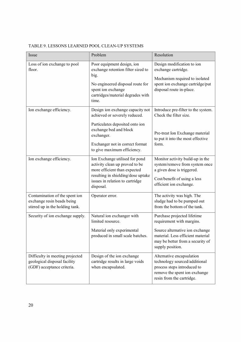
Table 9 provides a summary of the lessons learned relating to pool clean-up systems.
20
TABLE 9. LESSONS LEARNED POOL CLEAN-UP SYSTEMS
Issue Problem Resolution
Loss of ion exchange to pool floor.
Poor equipment design, ion exchange retention filter sized to big.
No engineered disposal route for spent ion exchange cartridges/material degrades with time.
Design modification to ion exchange cartridge.
Mechanism required to isolated spent ion exchange cartridge/put disposal route in-place.
Ion exchange efficiency. Design ion exchange capacity not achieved or severely reduced.
Particulates deposited onto ion exchange bed and block exchanger.
Exchanger not in correct format to give maximum efficiency.
Introduce pre-filter to the system. Check the filter size.
Pre-treat Ion Exchange material to put it into the most effective form.
Ion exchange efficiency. Ion Exchange utilised for pond activity clean up proved to be more efficient than expected resulting in shielding/dose uptake issues in relation to cartridge disposal.
Monitor activity build-up in the system/remove from system once a given dose is triggered.
Cost/benefit of using a less efficient ion exchange.
Contamination of the spent ion exchange resin beads being stirred up in the holding tank.
Operator error. The activity was high. The sludge had to be pumped out from the bottom of the tank.
Security of ion exchange supply. Natural ion exchanger with limited resource.
Material only experimental produced in small scale batches.
Purchase projected lifetime requirement with margins.
Source alternative ion exchange material. Less efficient material may be better from a security of supply position.
Difficulty in meeting projected geological disposal facility (GDF) acceptance criteria.
Design of the ion exchange cartridge results in large voids when encapsulated.
Alternative encapsulation technology sourced/additional process steps introduced to remove the spent ion exchange resin from the cartridge.

21
2.3.5. Spent fuel pool cooling
The heat removal systems of wet storage facilities shall ensure that the bulk temperature of the pool water remains within safe limits during normal operation and anticipated operational occurrences. Accordingly, the design should ensure that variations and rates in change of the temperature of the pool medium and affected facility components can be maintained within acceptable limits during operations, as identified and specified during the design process.
The primary concern is to protect the components, systems and the inventory from damage. Pool operating temperature, however, tends to be driven by factors associated with pool building humidity, the comfort to operators or the impact of condensation on ancillary components such as electrical supplies or the potential to invoke a wet dry corrosion process to the concrete superstructure.
For the majority of spent fuels fuel clad corrosion is minimal at pool operating temperatures; i.e. 20–50°C. The exception is Magnox where the temperature is generally controlled around 15–20°C to minimise clad corrosion which produces hydrogen and corrosion products.
Other considerations in controlling pool temperatures at acceptable levels are related to the growth of pool water activity through leaching from CRUD or activity adsorbed onto the fuel clad surfaces or where micro cracks in the fuel clad exist; typically a 7–10°C rise in temperature will double the amount of activity leached.
The design basis for the majority of AR and AFR storage facilities was fuel cycles envisioned some 30, 40 or even 50 years ago. There are a number of situations where the design basis needs to be re-evaluated and enhancements (for example the addition of new heat exchangers, or security of supply) to the cooling system need to be made. These are:
• Increasing the storage capacity; for example re-racking campaigns; • Change to reference case spent fuels; for example a move to MOX or HBU fuels
(>40GW·d·(tHM)-1 for LWR); • Provision against loss of cooling; • It has also been suggested that the warming trend as a result of climate change should also be
evaluated.
Table 10 provides a summary of the lessons learned relating to spent fuel storage cooling systems.

22
TABLE 10. LESSONS LEARNED COOLING SYSTEMS
Issue Problem Resolution
Difficulty in maintaining a constant pool temperature.
The capacity of installed equipment (pumps through-put, heat exchangers heat removal capacity) was too high c.f. the required duty.
Installation of lower capacity equipment.
Spent fuel over-heating. No provision was made in the design of AR cooling pits for cooling during maintenance to the common water cooling system.
An independent cooling system has been installed to the AR cooling pits.
Heat Exchanger efficiency. Heat exchange primary circuit fouling by animal/biological species.
Fouling of primary circuit by fuel crud migration.
Use of filter/chemical agents species/UV.
Removal at source; use of localised extraction equipment.
Potential for flooding.
In a room adjacent to the pool, containing the cooling system equipment, there is a risk of flooding in case of a failure of an armature or a break in the pipe crossing the wall.
Reinforcement of weak points in the crossing and to the pipe in the plant room.
2.3.6. Ventilation
Ventilation and off-gas systems should be provided where necessary to ensure containment of airborne radioactive particulate materials during operational states and accident conditions.
Air being drawn into the area of the bays should be passed first through an effective air filter, to prevent dust from settling on the surface of the pool water. Otherwise this dust will later act to clog pool filters, contributing to unnecessary levels of radioactive waste handling.
Where skimmers are used to remove dust from the bay surface, the flow of air in the bays should be in the same direction as the flow of water towards the skimmer, so that the air flow assists the skimming action.
2.3.7. Visibility
The use of underwater lighting greatly promotes visibility through the water in the bays during maintenance and operating activities. Where lights are left on continuously they can promote biological growth within the spent fuel pool; especially in the vicinity of the light. Employing UV lighting, changing

23
the wavelength of the light or reducing its intensity of the light source are all methods which can mitigate biological growth.
The ease of access and maintenance of light sources should be considered early in the design phase.
Table 11 summarises the lessons learned in relation to pool water visibility.
2.3.8. Surveillance and monitoring
A storage pool is an active system which requires continuous monitoring, the water chemistry needs to be controlled (see section 2.3.2) and periodic maintenance needs to be undertaken.
It is now becoming a common practice for spent fuel storage facilities to be operated beyond their original planned life; as closure of the nuclear cycle has not been completed to date. It is important that the effects of extended operation be anticipated and monitored to ensure continued safety is maintained. The spent fuel storage facility systems, structures and components (SSCs) gradually change with time and use. Some of these changes may be beneficial in the case of spent fuel residual heat or concrete curing, for others they are deleterious as in the corrosion of metal or degradation of polymers due to radiation effects.
For effective condition monitoring the normal operating margins for the SSCs need to be defined, and action levels set for investigation and remedial action. A good practice is to have a dash board (green, amber red) displaying key SSCs on the plant and in daily management/team meetings showing the status.
References [1, 12] provide further guidance on aging management and the SSCs which need to be monitored.
2.3.8.1. Spent fuel monitoring
The condition monitoring of spent fuel assemblies is routinely evaluated AR and AFR, indirectly, through the chemical and radiochemical analysis of the coolant water in the spent fuel pool (see Section 2.3.2.). AR spent fuel monitoring has also been used by fuel vendors to collate data on fuel performance in-reactor. In some cases spent fuel monitoring is also a requirement of the national regulator. AR inspections tend to be focused on the performance of new fuel designs and the impact of advanced fuel cycles. The spent fuel assemblies are visually inspected for signs of corrosion and fuel assembly geometrical changes; for example length. In addition eddy current and ultrasonic testing are also utilised to establish fuel pin integrity and oxide growth.
A technique such as eddy current testing has been developed over the years by fuel vendors to support the location of fuel clad defects and has the ability to quantify:
• Defect location; • Estimation global penetration; • Axial and circumferential wear lengths; • Loss of wall thickness; • Extent of micro cracks; • Dimension or shape of the bulge.

24
TABLE 11. LESSONS LEARNED POOL WATER VISIBILITY
Issue Problem Resolution
Plant operators evacuated to safe zone.
See Table 8. See Table 8.
Biological growth in storage pool.
See Table 6. See Table 6.
Loss of SiO2 from BoraflexTM can create visibility problems for plant operators.
See Section 2.3.4. See Section 2.3.4.
Fuel handling and inspections have progressed in-line with technology developments with respect to digital imaging. Advances have led to the routine use of off-the-shelf inexpensive high definition video cameras and DVD recorders. Where the fuel rods and fuel assembly structures can be easily accessed, plant operators can be used to make a record of fuel assembly condition during fuel loading operations or prior to fuel retrieval operations; for example Fig. 6. Recordings can be easily transited to technical support personnel for further analysis when fuel assembly condition is suspect. Previously fuel assembly inspections required specialist camera support teams and on the job experts.
Where a fuel assembly shroud is an integral part of the fuel assembly, visually checking or establishing beginning of storage condition of the fuel clad is problematic. In such cases the convention has been to check the ease or clearances of the fuel assembly in relation to removal and loading to reactor channels and storage racks. Such a technique provides a guide on the condition of the fuel assembly in terms of dimensional changes. An advanced warning on fuel clad integrity is obtained during irradiation through checking reactor operation chemistry. Integrity is confirmed on discharge by ‘sipping’ or storage pool liquor sampling.
For certain fuel types the deployment of an endoscope has been used effectively to establish fuel rod/assembly condition. In the case of WWER fuel inspections this can be particularly problematic for fuel designs without detachable top nozzles. Inspection stands have been developed which enable complete dismantling of the fuel assembly to facilitate inspection; for example Fig. 7. The inspection equipment incorporates the following features:
• Modules for shroud removal/including filter unit; • TV module; • Ultrasonic modules for leak testing; • Eddy current module for establish rod integrity and oxide layer thickness; • Module for testing internal pressure; • Repair module; • Containers for storing rods.

25
FIG. 6. Visual inspection of a FA using off-the-shelf
video camera.
FIG. 7. Fuel assembly inspection equipment for
WWER fuel.
2.3.8.2. Facility components
Operating experience to date demonstrates that proper attention to material selection and environmental control can result in several decades of operations without substantial impacts of SSC failures. Where operators have neglected aging management the consequences can be expensive.
The most traditional technique in monitoring the condition of wetted storage components is through deploying corrosion coupons. Corrosion coupons are also used to evaluate the performance of new components to be used in the fabrication of storage racks etc. As shown in Fig. 8.
FIG. 8. Holder showing coupons for in-pool corrosion monitoring.

26
In addition to corrosion coupons there are a variety of non-destructive techniques for confirming the on-going performance such as Acoustic monitoring of pool liners. The techniques in common use in Member States are discussed and presented in greater detail in [5].
2.3.9. Outdoor storage pools
The continued operation of outdoor storage pools presents a number of operational issues in relation to the maintenance of pool handlers and ancillary equipment and undertaking operations in cold weather.
Table 12 summarises the lessons learned in relation to the operation of outdoor pools.
2.3.10. Ad-hoc operations
One of the advantages of a spent fuel storage pool is the biological shield, i.e. water coverage, can be used flexibly for a variety of operations; which cannot be readily undertaken in by hot cells. One example of an ad-hoc operation is the cleaning of spent fuel.
Table 13 summarises the lessons learned in relation to ad-hoc operations.
TABLE 12. LESSONS LEARNED OPERATION OF OUTDOOR POOLS
Issue Problem Resolution
Fuel movements stopped due to operating temperature.
Engineering substantiation of the SSCs concluded that pool handling machines could not be used when the operating temperature falls below 0ºC.
No resolution.
Review and challenge original engineering judgement.
The local sea air environment found to be considerably more aggressive than the original design expectations for protective coatings used on major plant.
Pool handlers and other equipment have to undergo major refurbished on a frequent basis (every 5 years).
Refurbishment programmes take out of service key plant for months at a time which impacts on the overall plant operability.
Source alternative coatings which are more resistant to the operating environment.
Biological growth in storage pool.
See Table 5. See Table 5.

27
TABLE 13. LESSONS LEARNED AD-HOC OPERATIONS
Issue Problem Resolution
30 Fuel assemblies being chemically cleaned were significantly damaged.
Loss of cooling to cleaning tank in spent fuel pool service shaft.
The incident is described in detail in the fourth national report of Hungary prepared in the framework of the convention on nuclear safety in 2007. This national report is available on the web site of the Hungarian Atomic Energy Authority (www.haea.gov.hu).
2.4. SPENT FUEL PERFORMANCE
In some member states the experience in wet storing spent nuclear fuel is around 55 years. Wet storage continues to dominate as the primary method for storing spent nuclear fuel; >80% of all spent fuel is wet stored. The benefits provided by this technology are mainly associated with cooling efficiency and shielding. It also facilitates safeguards and one-off fuel inspection/examination exercises.
2.4.1. General performance
For primary barrier or containment purposes, cladding corrosion is the factor of most interest in wet storage. However, retention of fuel assembly structure integrity also becomes the overriding factor when retrieval is taken into consideration. A detailed review of the degradation mechanisms of various fuel types under wet storage conditions is provided [5] and will not reproduced here.
Reference [5] reports the general performance for different fuel clads as:
For zirconium alloy clad fuel, data exist for continuous pool storage of greater than 50 years. This data indicates cladding corrosion to be extremely low (1 × 10⁻⁶ µm.yr-1) and, therefore, corrosion is not viewed to be the time-limiting factor for prolonged wet spent fuel storage; even under poor pool chemistry conditions.
For stainless steel clad fuels, continuous storage experience of 32 years (LWR) and 38 years (AGR) exists. Although the general cladding corrosion rates for these fuels are significantly higher than for zirconium-based alloys (at ~0.1 µm·yr-1), general corrosion is not a time limiting factor for the storage durations currently envisaged (up to 100 years). For AGR fuel, particular attention to pool water chemistry is required as parts of the fuel stringer become sensitised during reactor operation; [5] provides further information.
Magnesium alloy clad fuel is particularly susceptible to cladding corrosion under wet storage conditions. Although a protective magnesium hydroxide film is initially formed, the presence of any aggressive ions in the water promotes the dissolution of the protective oxide film and leaves the cladding open to pitting attack. For this reason, Magnox fuel is stored in dosed pool water and storage duration tends to be limited; normally 1–2 years, but longer durations 5–17 years have been reported.

28
Table 14 summaries the lessons learned in relation to spent fuel performance in wet storage.
In general, wet storage of spent fuel only appears to be limited by adverse pool chemistry conditions or deterioration of the fuel storage pool structure. The following is an example of the experience of one storage operator:
• At present the total amount of spent fuel assemblies stored in independent spent fuel storage facility (ISFSF) is 8.521. Only 12 of them are stored in hermetical casings; i.e. 0.14% of the fuel required some conditioning.
TABLE 14. LESSONS LEARNED SPENT FUEL PERFORMANCE
Issue Problem Resolution
Top nozzle separation during fuel handling of Old PWR fuel assemblies.
(Issue for storage operators with pre 1990s fuel).
Detailed hot-cell examination showed that the sleeve failed due to inter-granular stress corrosion cracking of the bulge joint (see Fig. 9).
The failure mechanism is of concern to old designed PWR fuel where the bulge joint comprises a connection between a zirconium tube and a stainless steel tube which has become sensitized during manufacture.
Failure cause through a combination of corrosion and applied stress to the bulge joints during fuel handling.
Where the top nozzle has separated. The fuel assembly has to be handled with specially designed tool (e.g. Fig. 10).
The condition of long stored PWR fuel needs to be check prior to fuel movement for signs of corrosion at the bulge joint.
Care should be taken to limited applied stress to the bulge joint through twisting action.
Accelerated fuel clad degradation in storage (Magnox spent fuel).
Failure to maintain optimum storage conditions. Clad degradation due to a combination of concentration of impurities too high and pH of protective storage medium too low.
Quality plans and procedures introduced to ensure correct operating conditions are maintained.
Caesium excursion as a result of fuel clad perforation during storage (AGR spent fuel).
Failure mechanism is detailed in [5]. Operator was advised that he was working within safe limits. Original assumptions flawed sensitized stainless steel clad appears to have no tolerance to any concentration of chloride.
Store spent fuel in a protective storage chemistry.

29
FIG. 9. Inspection of a PWR bulge joint. FIG. 10. Tool for handling fuel assemblies with no
top nozzle.
2.5. FACILITY MODIFICATIONS
In general spent fuel storage facility modifications are carried-out in response to a number of changes to the operating environment. These include:
• A change in national or international legislation; for example changes to standards. For older facilities this often involves up-grades to meet the international recognised seismic standard;
• In response to a business need; for example increasing storage capacity or accommodating new fuel designs;
• To over-come an operational difficultly; for example reliability issue with a piece of plant; • To incorporate best practice; for example materials exclusion zones.
An example of the diverse range of technical and safety modifications that had been undertaken at one ISFSF are:
• Installation of a manipulator for spent fuel transfers; • Enhancement of air-conditioning systems based on the requirements of fire protection; • Enhancement of filtration of pond water by a filtration unit for capturing micro-organisms in
pond water, including liquidation of filtration cartridges; • Modification of decontamination system; • Installation of detection systems to monitor fuel assembly tightness (sipping in pool) and
corrosion of pool linings; • Modernisation of radiation control system and instrumentation; • Disposition modifications of controlled area; • Modification of the entrance for personnel into the ISFSF building; • Building modifications resulting from new technology requirements; • Monitoring of building structures life and technological systems including monitoring of spent
fuel conditions.
The following sub-chapters evaluate a number of common modifications to spent fuel storage facilities in more detail.

30
2.5.1. Fuel handling systems
Over the years a number of safety features have been incorporated into spent fuel or spent fuel container handling systems. Examples of safety up-grades either incorporated into the design of new fuel handling systems or modifications to existing systems are:
• Bolt and lock for positioning of spent fuel storage containers • Computer/laser aided guidance system for accurate spent fuel placement • Gamma inter-locks which prevent fuel assembly or container over-raise • Weight limiters to prevent fuel racks being picked up with the fuel assembly • The speed of the fuel removal machine limited to minimise damage during a collision • The fuel moved inside a protective shroud to prevent damage during horizontal movements • Horizontal travel limiters to over-come alignment problems in automated systems • Zoning of plant equipment, for example the building crane, to prevent potential drops during fuel
handling operations
Table 15 summaries the lessons learned in relation to modifications to fuel handling systems. An example of a remote operable fuel handling system is shown in Fig. 11.
TABLE 15. LESSONS LEARNED FUEL HANDLING SYSTEMS
Issue Problem Resolution
Fuel handling machine trips out on a routine basis.
Plant operability issue.
Alignment issues with hardwired fuel handling machine travel interlocks.
Associated with wear and tear of the machine with time.
Corrective maintenance activity scheduled to resolve the issue.
Fuel handling machine trips out on a routine basis.
Redundant control system software. See Section 2.6.2.
Requires replacement or up-grade of the control system.
Temporary fix involves operation with software engineer present or use in maintenance mode under management supervision.

31
FIG. 11. Replacement remote controlled fuel manipulator.
2.5.2. Storage capacity enhancements
Unlike their AR counterparts which are limited by the original pool surface area, AFR storage facilities are often designed with expansion in mind; i.e. the ability to add multiple storage pools or bays. For many NPPs designed in the 1970s and 1980s the original spent fuel management intention was for the fuel to be reprocessed. AR storage capacity was designed around space to off-load the entire reactor core (LWR reactors) and a limited buffer storage capacity (~3 years).
Through a combination of factors (delays in reprocessing capacity, the cost of reprocessing, government decisions or simply taking a wait and see policy) many NPPs have had to or will have to increase storage capacity at some point. To solve the problems associated with limited pool storage at older reactors, various methods have been used to improve pool storage efficiencies. These pool enhancements have included the use of neutron absorbing plates in fuel pool racks and credit for reduced reactivity, commonly known as burnup credit. Figure 12 provides a graphical representation of the storage enhancements to one NPP’s AR spent fuel storage pool as a function of time.
Clearly the projected storage capability (2017) bears no relation to the original design intent; which was based on the spent fuel being reprocessed. The changes also show changes in NPP accountancy life; the latest reflecting the general trend towards 60 years of operations (LWR NPPs).

32
FIG. 12. Plot showing modifications to AR storage capability with time
In terms of storage rack design development this has involved a move to towards ever decreasing spacing of fuel or increasing the t·HM·.m-2. Initial steps were to decrease the spacing between spent fuel assemblies without the inclusion of neutron absorbing materials and later with the inclusion of neutron absorbing materials; an example is given Table 16.
Methods for expanding the capacity of spent fuel storage facilities are discussed in more detail in [13] and Fig. 13 shows some examples of compact or high density racks.
In increasing in-pool storage capacity consideration also has to be given to the peak heat loading, which may call for additional cooling capability to be installed (see Fig. 12.), and floor loading in terms of t·m-2.
With the move towards greater fuel cycle efficiencies this has led to increased fuel burnup, which has been achieved through increasing initial fuel enrichments. Increased fuel enrichments results in greater fuel reactivity, for the same fuel design, and decreases the sub-criticality safety margin for the same storage rack. In some cases this has meant that high density storage racks can no longer be used or only partly, by adding administrative controls or through blanking positions.
TABLE 16. STORAGE CAPACITY (FUNCTION OF FUEL PITCH AND NEUTRON ABSORBER)
Pool capacity/FAs FA spacing Neutron absorber
106 510mm No 240 330mm No 438 260mm Yes
Burn-up credit introduced to meet new fuel design
Third Heat Exchanger also installed to accommodate greater decay heat
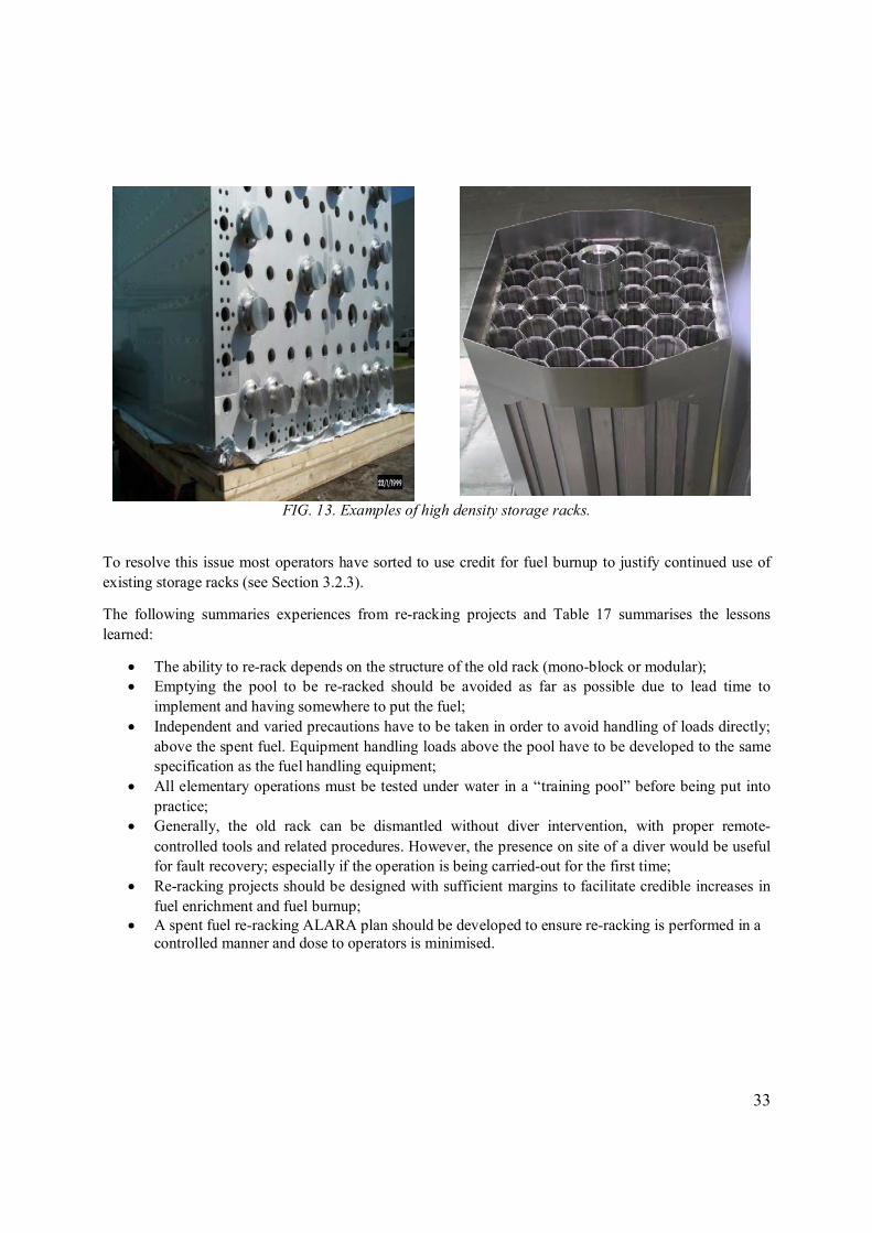
33
FIG. 13. Examples of high density storage racks.
To resolve this issue most operators have sorted to use credit for fuel burnup to justify continued use of existing storage racks (see Section 3.2.3).
The following summaries experiences from re-racking projects and Table 17 summarises the lessons learned:
• The ability to re-rack depends on the structure of the old rack (mono-block or modular); • Emptying the pool to be re-racked should be avoided as far as possible due to lead time to
implement and having somewhere to put the fuel; • Independent and varied precautions have to be taken in order to avoid handling of loads directly;
above the spent fuel. Equipment handling loads above the pool have to be developed to the same specification as the fuel handling equipment;
• All elementary operations must be tested under water in a “training pool” before being put into practice;
• Generally, the old rack can be dismantled without diver intervention, with proper remote-controlled tools and related procedures. However, the presence on site of a diver would be useful for fault recovery; especially if the operation is being carried-out for the first time;
• Re-racking projects should be designed with sufficient margins to facilitate credible increases in fuel enrichment and fuel burnup;
• A spent fuel re-racking ALARA plan should be developed to ensure re-racking is performed in a controlled manner and dose to operators is minimised.

34
TABLE 17. LESSONS LEARNED STORAGE CAPACITY ENHANCEMENTS
Issue Problem Resolution
Probability of damage to pool liner increased.
The re-racking process involves fuel reshuffling and underwater cutting, welding, and heavy load transfers all parts of this process are subject to loads being dropped on the pool liner which can lead to damage.
Operations should be undertaken under supervision. Plans should be developed to minimise the number of fuel and equipment moves.
Provision of additional shielding if divers used to undertake cutting and welding operations.
Depending on the rack design underwater cutting and welding operations may be necessary to replace existing storage racks with high density racks.
This is usually achieved by rearrangement of fuel (see issue below).
Probability of fuel handling drop increased.
Additional fuel transfer operations are required to implement re-racking.
See Section 2.3.2.
Dose uptake to plant operators. Does incurred by maintenance staff in introducing additional storage capacity.
Evaluate the potential to maximise remote handling operations to minimise dose to operators/design of the system should incorporate feature to minimise impact on operators.
Undertake cost versus dose detriment exercise.
No further opportunity to increase storage capacity.
Original design assumptions insufficient.
Excess fuel needs to be moved to an AFR storage facility, or reprocessed or new storage facility provided.
Re-racking requires fuel handling machine/location system to be modified.
New storage system has a different geometry to the old system.
A necessity of introducing a new racking system, however, the original design assessment should look to keep modifications to a minimum.
E.g. a racking system should be designed around existing pool grid locations if the fuel handling system works on physical bolt and lock locating system.

35
2.5.3. Licensing burnup credit
Taking credit in criticality assessment for the reduction in spent fuel nuclear reactivity as a result of irradiation, burnup credit, is a very complex issue. It requires highly sophisticated methodologies for calculating the isotopic inventory of the irradiated fuel for which burnup credit is taken. This knowledge is gained by using depletion codes. The uncertainty of a depletion code is controlled and established through verification of that code, usually by comparison with suitable and appropriate experiments. In-core reactor measurement data are important for verifications of depletion codes.
For burnup credit applications, particular significance is attached to comparisons of calculated to measured isotopic concentrations. Difficulties can be encountered in obtaining consistent isotopic analyses; as the product separation is a delicate procedure and there can be difficulties in obtaining accurate result for some species. Due to the depletion analysis, that has to be performed to determine the isotopic content, the results of the criticality calculations become dependent on the reactor operation conditions assumed for the depletion analysis.
Given the wide variety of fuel irradiation histories which can be stored, it is necessary to look for a bounding irradiation history given by those fuel operation conditions that lead to the highest spent fuel reactivity in the criticality analysis.
In terms of criticality methodologies used in spent fuel storage these vary from one Member State and operator to the next with the application of varying degrees of pessimism from:
• Fresh fuel (most pessimistic) • Credit for actinides only • Credit for actinides and fission products (least pessimistic)
Burnup credit and its application in spent fuel storage are discussed in greater detail in the following references [14–18].
Table 18 presents a number of issues associated with licensing burnup credit TABLE 18. LESSONS LEARNT LICENSING BURNUP CREDIT Issue Comment No international accepted standard or guidelines
Assists operators and regulators in countries which have not adopted burnup credit to date For countries already using burnup credit it enables them to say they are working to an accepted international standard
Limited measured irradiation libraries for all fuel types
Some Member States do not have the resources to call upon to undertake detailed analysis of fuel types specific to their country and irradiation history
Burnup credit seen as the last resort The application of burnup credit can only be justified if it can be demonstrated that sub-criticality cannot be maintained by the use of means such as engineered barriers
Approval subject to verification Reliance on reactor operating data and burnup codes only considered acceptable if supported by confirmatory in-pool burnup measurements

36
2.5.4. Change to AR fuel route
NPP design does not usually provide the flexibility to change the fuel route without a major plant modification. This normally precludes such modifications on the grounds that the NPP would need to be shut-down for a prolonged period and there are risks associated with a return to service.
One specific example where the fuel route has been changed has been a MAGNOX NPP that has been shut-down and the fuel is still awaiting discharge from the core [19]. The normal fuel route at a MAGNOX NPP is to discharge fuel stringers into the AR storage pool for initial cooling prior to onward wet transportation for reprocessing. Storage durations were usually short <1 year. The alternative fuel route involves discharging the spent fuel stringer directly to the transportation cask. This approach was introduced to over-come potential issues with fuel clad degradation in wet storage [5] as a result of uncertainties with the availability of MAGNOX reprocessing facilities, but can also lead to improved cask packing densities. In this example in-core cooling, initially in carbon dioxide, is used to reach a position where the fuel can be discharged directly to a transportation cask.
The revised process facilitates a just-in-time approach and avoids a prolonged dwell for MAGNOX fuel in wet storage prior to reprocessing.
2.6. MAINTENANCE
Aging management is an essential requirement to maintain plant condition & reliability. The frequency of maintenance schedules are set during the design phase and are incorporated into plant management systems. Most of these systems are now computer based and provide automated prompts to maintenance engineers for routine safety checks, scheduled and statuary maintenance schedules for each plant item. These systems are also used to record when the maintenance was carried-out, plant reliability data and reporting of faults (to enable plant trending data to be compiled).
The following sub-sections cover plant areas where responses were received to the circulated questionnaires.
2.6.1. Pool liner
The opportunity to inspect spent fuel pool liners once the fuel racks or storage containers have been installed is limited. Liner integrity is therefore implied through leak detection systems embedded between the concrete structure and the pool liner; i.e. retrospective monitoring.
Good practices which have been highlighted in response to the questionnaires are: To inspect the pool liner during re-racking operations: To make a thorough inspection of the liner at different temperatures; to keep appropriate tools ready for the repair of small pool leakages.
Table 19 summaries the lessons learned in pool liner.

37
TABLE 19. LESSONS LEARNED POOL LINER
Issue Problem Resolution
Pool liner buckled during commissioning
Water ingress below the pool liner led to distortion from its original shape
Dewater storage pit and replacement
Pool liner leaks A number of operator have reported leakage of pool liners which have required repair
Failure of welds
Dewater pool and reconstruct pool liner
Methods have also been developed for underwater repair. It is, however, important to ensure any water trapped between the liner and the structure is removed.
2.6.2. Control systems/impact of technology
In the 1980s many plant items such as pond handlers, cranes, records management systems moved from a reliance on ‘manual’ control to ‘sophisticated’ software controlled systems. Many of these systems are one-offs or tailor made. While such systems offer major benefits (examples include: Reduction or removal of operator error; Hard wired interlocks; Zoned areas) and have been a mechanism for reducing operator dose uptake, the very nature of them being one-off products has meant that as they age they suffer from reliability problems, and both the software and hardware become redundant (either through not being supported by the manufacturer or the skill base has not been maintained).
Operating experience to date has shown that many control systems have needed to be replaced between 10–20 years.
Table 20 summarises the lessons learned the operation of control systems/impact of technology

38
TABLE 20. LESSONS LEARNED CONTROL SYSTEMS/IMPACT OF TECHNOLOGY
Issue Problem Resolution
Redundant Control System. Manufacturer goes out of business or system is no longer supported by the manufacturer. Software no longer supported by the manufacturer. Hard-ware no longer manufactured/no spares available. System built by an individual whom has retired from the original supplier or left and took the know-how with them.
Replace redundant system with a new one. Look to deploy Off-the-Shelf system in terms of hardware and software.
2.6.3. Degradation of facility components
There are a number of wetted materials used for example in storage racks, as water retention materials in expansion joints for pools without stainless steel liners, coatings or simply materials of construction. Some of the ageing processes these materials are subjected to include:
• General corrosion; • Radiation hardening.
The durability of spent nuclear fuel and facility components in wet storage is discussed in detail in reference [6]. Some of the aging processes lead to deterioration of the material which can impact on its original design function; for example the general thinning of metals. The degradation process can also lead to secondary effects such as spalling of corrosion products into the pool water and migration into service system or can accelerate corrosion processes of other materials. Table 21 summarises the lessons learned in relation to materials degradation.
There were a number of reports associated with the degradation of polymeric neutron absorbing material used in spent fuel storage racks; due to radiation hardening of the polymers used in these systems. The degradation of the polymeric material results in both boron and SiO2 particulates being released from the material into the storage pool. The impact on pool storage operations are several fold:
The primary safety function of the neutron absorber reduces with time affecting the sub-criticality safety margin. Continued operations of such system are, therefore, subject to periodic review. Degradation also results in the release of SiO2 into pool water. This can result in issues associated with its accumulation, visibility and need to remove. One operator reported problems with SiO2 contamination between NPP units through migration through common systems. Filtration and suppression systems have been utilised to maintain limits.

39
TABLE 21. LESSONS LEARNED DEGRADATION OF FACILITY COMPONENTS
Issue Problem Resolution
Neutron absorber sub-criticality safety margin reduced with time.
Loss of boron neutron absorbing particles from polymeric neutron absorber due to radiation hardening to the pool water reduces the concentration of absorber in the original material.
One method of establishing the remaining life of these materials is by using a computer code; for example “RACKLIFE’ [20].
Replace neutron absorber with alternative material such as boronated stainless steel.
Migration of SiO2 particles from neutron absorber to pool water. and potential for them to be entrained in primary cooling systems, cross contamination to other AR storage where common water/cooling/clean-up system used.
Radiation hardening of polymeric neutron absorber material releases SiO2 particles this leads to the following operational issues:
• Entrainment in cooling system;
• Cross contamination between NPP units through common AR systems.
Replace neutron absorber with alternative material such as boronated stainless steel.
Protective coating (racks, lifting beams) degraded in areas.
Exposed base metal is subject to corrosion under pool chemistry conditions.
Integrity not impacted, but corrosion is a site for activity adsorption and has an impact on dose uptake to operators, and maintenance or disposal operations.
Improve quality assurance system used in purchasing process.
Replace with stainless steel systems.
2.6.4. Spent fuel repairs
A review of fuel failures in water cooled reactors is provided in [21]. Over a review period (1994–2006) the general trend was downwards in terms of leakers in water reactors with a reduction of around 75%. The main causes of fuel failures: PWR reactors are dominated by grid to rod fretting failures; BWR failures tend to occur either as CRUD induced localised corrosion or from pellet clad interaction stress corrosion cracking; WWER-1000 from debris damage, fretting wear of fuel rod plugs in the bottom support grids and displacement of fuel rods during transportation; WWER-440 fretting wear, debris induced damage to fuel rods and deposits in the fuel rod bundle; CANDU debris damage, fabrication flaws and unknown.

40
The number of failures resulting from manufacturing defects has decreased significantly since the early years of fuel assembly manufacture; mainly due to improvements in the manufacturing processes and supporting quality assurance processes. Failures are tend to be limited to end plug, welding defects and tubing reduction flaws.
Two kinds of repair can take place:
• Complete exchange of assembly skeleton by transferring all the sound rods from the damaged assembly into a new skeleton
• Extraction of leaking or failed rods and replacement by dummy or fuelled rods
The ease of Fuel assembly repair depends upon the Fuel assembly design. Some designs being more amenable to repair; having removal top nozzles and pin end caps which can be easily grappled. Fuel Assemblies which are designed for repair facilitate more compact work stations; as for example the rotating of whole assemblies can be avoided. They also result in reduced costs and time to repair. For other Fuel Assemblies a variety of equipment may be required for the removal of welded locking pins to cutting equipment to remove the water channel shroud and/or the top nozzle.
Where a Fuel assembly has been subject to significant repair a leak test, some countries, may be required before the fuel can be put back into the reactor. The other side of spent fuel repairs is the management of the resultant wastes as storage racks were not designed for wastes. Methods need to be put in-place for managing failed pins these can vary between sealable cans to surrogate Fuel Assemblies (which look like a standard Fuel assembly, where the fuel pins are replaced by single pin over cans for accommodating failed pins).
Due to the design of the fuel route at gas reactors there is no mechanism for Fuel Assemblies or single fuel elements to be repaired. Further information on fuel assembly repair techniques and experiences are provided in references [22, 23].
Table 22 summarises the lessons learned in relation to spent fuel repairs

41
TABLE 22. LESSONS LEARNED SPENT FUEL REPAIRS
Issue Problem Resolution
Prevention of transfer of confidential information on vendors fuel behaviour.
Operator know how in repairing fuel from different suppliers/use of a sub-contractor to provide this service.
To protect fuel design and performance information the fuel vendor should be used to repair their own fuel.
Repair not completed. The operating windows for repair of fuel assemblies AR are limited and are managed around other NPP activities.
Diagnostics or establishing what the problem is/what needs to be replaced is an important and potentially lengthy part of the process.
Fuel inspection to establish extent of repair should be carried-out several months before the planned repair.
Balancing neutronics. Need to a have a range of fuel enrichments available to balance fuel assembly reactivity.
The symmetrical assemblies should be removed with the defective fuel assembly.
If not removed then a replacement fuel assembly with similar reactivity (reduced enrichment) needs to be substituted to balance the neutron flux.
2.7. TRANSFER FROM WET STORAGE TO NEXT FUEL MANAGEMENT PHASE (SPENT FUEL RETRIEVAL)
As spent fuel storage is only an interim step in the back end of the fuel cycle, at some point in time the spent fuel will need to be retrieved and transferred to the next stage of the fuel management process.
One of the key objectives/safety requirements of spent fuel storage is to maintain the spent fuel assembly and/or the storage container in a condition which does not compromise ultimate retrieval. With a move to increased interim storage duration, 50–100 years or even longer are now being considered, then it is unlikely that the operators and management team that put the fuel into storage will still be there when the fuel is retrieved. This highlights the need for good record management (what is being stored, design and condition), maintenance of tools and systems to enable retrieval and sound succession planning to ensure operators are adequately trained.
Table 23 summaries the lessons learned in relation to the transfer from wet storage to the next fuel management phase; i.e. spent fuel retrieval.

42
TABLE 23. LESSONS LEARNED SPENT FUEL RETRIEVAL
Issue Problem Resolution
Spent fuel assembly in non-standard format.
Non-standard lifting feature/no lifting tool available.
Conditioned spent fuel assembly not compatible with next fuel management phase.
Incomplete records. Can only see an over-pack. No design details or details of how or why the fuel assembly has been conditioned.
Lead time to generate a conditioned solution.
Characterise and engineer fuel handling tool.
Generate engineered scheme to re-pack fuel assembly into a format compatible with next management phase.
Devise scheme for intrusive inspection/characterisation. Forward plan depends on the result of the inspection.
Plan early (solutions can have year plus lead times).
Incomplete records. Records management
Have to use pessimistic assumptions in plant safety cases.
May reduce the management options available; i.e. excludes a reprocessing option.
Look to back-fit missing information.
All bounding assumptions used in the safety case.
Source missing data if possible.
Original fuel handling tools have become redundant or have been scrapped.
Do not meet latest safety standards.
Cannot move the fuel.
Engineer new fuel handling tools to the latest safety standards.
(Adds delays to fuel retrieval programme).
Redundant operating procedures or loss of operator ‘know-how’.
No spent fuel handling operations during storage only phase leads to operating procedures, fuel handling tooling and ‘know-how’ becoming redundant prior to final spent fuel retrieval
Review existing operating procedures if still available and review against latest safety requirements or produce new ones. Undertake a training programme with operators using mock-ups.

43
TABLE 23. LESSONS LEARNED SPENT FUEL RETRIEVAL (cont.)
Issue Problem Resolution
Spent fuel integrity. Global operating experience may have highlighted potential fuel integrity issues (see section 2.4).
Additional spent fuel CCTV inspection required to look for signs of degradation mechanisms which have been brought to the attention of operators.
Spent fuel storage operators need to keep a watching brief on the latest developments on spent fuel storage experience; as reported by organisations such as the IAEA.
Dropped fuel assembly has been made safe, but not conditioned.
Fuel assembly cannot be moved.
Tendency to leave damaged fuel to end of operations if they are in a safe condition and do not impact on fuel route activities.
This creates a problem for post operation clean out activities.
Characterise and engineer a scheme for recovery/conditioning into a format compatible with next management phase.
Redundant fuel handling System. Has not been used for many years.
System does not meet latest safety requirements.
Undertake a complete engineering review, introduce modifications to meet latest safety standards or replace whole system. The system will then need to be re-commissioned.
Unknown fuel assembly or fuel assembly in a condition not expected.
Fuel assembly cannot be removed. May limit the retrieval options available and delays facility defueling operations.
Retention, maintenance and recording of records.
Difficulty in retrieving fuel assemblies from storage racks or containers.
Lack of flexibility in fuel handling systems can cause problems in retrieval of fuel, dependant on the orientation of the fuel in the rack; i.e. whether they are slightly leaning.
Fuel handling machine operated in maintenance mode under operator supervision.

44
TABLE 23. LESSONS LEARNED SPENT FUEL RETRIEVAL (cont.)
Issue Problem Resolution
Radiolysis in cask during wet transport.
Excessive hydrogen evolution from a combination of materials present in the transport cask requires a limitation to be put on transport duration.
Consideration should be given to deploying catalyst to either remove the hydrogen or in the case of radiolysis recombine the hydrogen and oxygen.
Safety case made that there is no detonable source.

45
3. DRY STORAGE FACILITIES
Some of the first dry storage applications were those associated with AR storage for gas cooled reactors. Later developments included the forged metal casks and variants from this original design in order to reduce production costs. Table 24 lists the main types of storage systems available and the advantages and disadvantages of each system.
Dry storage is a flexible solution which can easily be adapted to a larger inventory, but it is more sensitive to changes in fuel characteristics (i.e. not easily adapted from one fuel type to another) and the waste management policy than wet storage. For example, if there is a significant change in the regulations or simply in the storage duration this can call into question the design of the system and can lead to the retrieval of the spent fuel assemblies, which is not an easy operation in the case of dry storage.
3.1. PLANNING
The most important aspect of planning for dry storage is timing. Early planning and communications with both the regulators and key stakeholders is essential. While the time needed to go from initial plans to the loading of spent fuel into a licenced cask or storage facility will vary among Member States, experience has shown that it is between a couple of years up to a decade; depending on the number and types of approvals needed.
Where continued operation of an NPP is dependent on new storage facilities becoming available allowing sufficient lead time for implementation is essential.
The transport of spent fuel from AR spent fuel storage to an independent spent fuel storage facility (ISFSF) is usually driven by AR pool storage capacity. The project schedule/programme therefore, needs to be constructed backwards from the point when the AR storage pool would be full to ensure that the ISFSF is available to receive spent fuel on the date required; a suitable operating margin should be incorporated to over-come any delays in project delivery.
At the planning stage a realistic estimate needs to be made of the projected amount of spent fuel to be stored; taking into account the potential for life extensions to the NPP or even new NPP construction. Dry storage facilities can require significant areas of land, regardless of type, and hence if the total number of spent fuel assemblies is not well defined then a greater footprint should be reserved to allow for extensions.
At all stages of the project plan from concept to implementation, close liaison between the organization responsible for the storage facility (for phases of its life) and the organization responsible for the NPP are required.

46
TA
BL
E 2
4. D
RY
ST
OR
AG
E S
YS
TE
MS
Dry
Sto
rage
Sys
tem
A
dvan
tage
s D
isad
vant
ages
Mod
ular
vau
lt d
ry s
tore
(M
VD
S).
S
tand
-alo
ne s
tora
ge f
acil
ity
inco
rpor
atin
g al
l sup
port
ing
serv
ices
.
Exp
anda
ble
thro
ugh
addi
ng a
ddit
iona
l va
ults
.
Abi
lity
to
acco
mm
odat
e sh
ort-
cool
ed f
uel a
nd h
ighe
r bu
rnup
fue
l. H
eat
rem
oval
cap
abil
ity
lim
ited
by
indi
vidu
al v
ault
s; ~
1 M
W.
Red
uced
pro
cess
ing
tim
es a
t AR
as
com
plet
e fu
el a
ssem
bly
dryi
ng
in u
nder
take
n at
the
MV
DS
.
In p
rinc
iple
fue
l can
be
read
ily
insp
ecte
d in
the
fue
llin
g m
achi
ne.
In t
he e
vent
of
seal
fai
lure
the
fue
l ass
embl
y ca
n be
rea
dily
re
mov
ed a
nd a
new
sea
l fit
ted
to t
he s
tora
ge t
ube;
wit
hout
hav
ing
to b
ring
in
addi
tion
al e
quip
men
t or
ret
urn
fuel
to
the
load
ing
pool
.
Pro
visi
on c
an b
e m
ade
to a
ccom
mod
ate
fail
ed o
r da
mag
ed F
uel
Ass
embl
ies
in o
ver-
pack
s.
Up-
fron
t co
st.
Sto
rage
pro
visi
on b
y th
e va
ult.
Fle
xibi
lity,
for
exa
mpl
e ac
com
mod
atin
g di
ffer
ent
fuel
siz
es o
r fa
iled
Fue
l A
ssem
blie
s in
ove
r-pa
cks,
has
to
be in
corp
orat
ed i
nto
orig
inal
des
ign.
Nee
d to
pla
n ah
ead
for
expa
nsio
n.

47
TA
BL
E 2
4. D
RY
ST
OR
AG
E S
YS
TE
MS
(co
nt.)
Dry
Sto
rage
Sys
tem
A
dvan
tage
s D
isad
vant
ages
Met
al s
tora
ge c
asks
. S
ome
desi
gns
are
also
lic
ence
d fo
r tr
ansp
orta
tion
.
Incr
emen
tal s
tora
ge w
hich
avo
ids
up f
ront
larg
e in
vest
men
ts.
Mos
t ex
pens
ive
of t
he c
ask
stor
age
opti
ons.
Fue
l in
tegr
ity
is i
nfer
red
thro
ugh
mon
itor
ing
pres
sure
dro
p of
the
in
ters
pace
bet
wee
n in
ner
and
oute
r se
als.
Sin
gle
lid
doub
le s
eal
desi
gn r
equi
res
addi
tion
al f
acil
itie
s to
be
reta
ined
in
the
even
t of
out
er s
eal
failu
re;
the
avai
labi
lity
of
pool
or
a ho
t ce
ll.
Siz
e is
lim
ited
by
the
capa
bili
ty o
f fu
el c
onsi
gnor
’s f
acil
itie
s; f
or
exam
ple
floo
r lo
adin
g in
set
dow
n ar
eas,
phy
sica
l di
men
sion
s, c
rane
lo
adin
g li
mit
.
Can
onl
y be
use
d fo
r th
e de
sign
app
lica
tion
; i.e
. us
e fo
r ot
her
fuel
de
sign
s af
ter
cons
truc
tion
li
mit
ed
by
orig
inal
co
mpa
rtm
ent
dim
ensi
ons
etc.
.
Onl
y an
int
erim
ste
p; i
.e.
wou
ld b
e be
tter
if
the
cask
cou
ld a
lso
be
the
disp
osal
con
tain
er a
nd n
o fu
rthe
r co
ndit
ioni
ng w
as r
equi
red.
Con
cret
e ca
sks.
L
ow c
ost
solu
tion
to
incr
emen
tal s
tora
ge.
Idea
l for
low
bur
nup
long
sto
red
fuel
.
Fue
l in
tegr
ity
is r
elia
nt o
n th
e or
igin
al w
eld
clos
ure
and
chec
king
fo
r le
ak t
ight
ness
.
Not
sui
tabl
e fo
r hi
gh b
urnu
p or
MO
X f
uel
(unl
ess
long
coo
led)
due
to
the
red
uced
hea
t lo
adin
g ca
pabi
lity
com
pare
d to
oth
er s
yste
ms.
Can
onl
y be
use
d fo
r th
e de
sign
app
lica
tion
; i.e
. us
e fo
r ot
her
fuel
de
sign
s af
ter
cons
truc
tion
li
mit
ed
by
orig
inal
co
mpa
rtm
ent
dim
ensi
ons.

48
TA
BL
E 2
4. D
RY
ST
OR
AG
E S
YS
TE
MS
(co
nt.)
Dry
Sto
rage
Sys
tem
A
dvan
tage
s D
isad
vant
ages
Mul
ti-p
urpo
se
cani
ster
(M
PC
).
Des
ign
is
base
d on
us
e fr
om
crad
le
to
grav
e;
i.e.
st
orag
e,
tran
spor
tati
on a
nd d
ispo
sal.
Red
uces
fue
l han
dlin
g fr
eque
ncy.
Can
acc
omm
odat
e a
lim
ited
num
ber
of d
amag
ed f
uel c
onta
iner
s.
Pot
enti
al t
o re
duce
lif
ecyc
le c
osts
.
Has
to
be u
sed
in c
ombi
nati
on w
ith
othe
r sy
stem
s; f
or e
xam
ple
a tr
ansp
orta
tion
cas
k, s
tora
ge c
ask,
dis
posa
l ove
r-pa
ck.
Can
onl
y be
use
d fo
r th
e de
sign
app
lica
tion
; i.e
. us
e fo
r ot
her
fuel
de
sign
s af
ter
cons
truc
tion
li
mit
ed
by
orig
inal
co
mpa
rtm
ent
dim
ensi
ons.
Ven
tila
ted
conc
rete
cas
ks.
Low
er c
ost
solu
tion
c.f
. met
al c
ask
coun
terp
arts
.
Incr
emen
tal s
tora
ge w
hich
avo
ids
up f
ront
larg
e in
vest
men
ts.
Fue
l in
tegr
ity
is r
elia
nt o
n th
e or
igin
al c
anis
ter
seal
wel
d.
Pot
enti
al f
or S
tres
s C
orro
sion
Cra
ckin
g of
the
fue
l ca
nist
er i
n th
e lo
ng-t
erm
.
Rel
ianc
e on
oth
er s
yste
ms
if r
e-w
ork
is r
equi
red.
Can
onl
y be
use
d fo
r th
e de
sign
app
lica
tion
; i.e
. us
e fo
r ot
her
fuel
de
sign
s af
ter
cons
truc
tion
li
mit
ed
by
orig
inal
co
mpa
rtm
ent
dim
ensi
ons.

49
TA
BL
E 2
4. D
RY
ST
OR
AG
E S
YS
TE
MS
(co
nt.)
Dry
Sto
rage
Sys
tem
A
dvan
tage
s D
isad
vant
ages
Sil
os.
Low
er c
ost
solu
tion
c.f
. met
al c
ask
coun
terp
arts
.
Idea
l for
low
bur
nup
or lo
ng s
tore
d fu
el.
Can
onl
y be
use
d fo
r th
e de
sign
app
lica
tion
; i.e
. us
e fo
r ot
her
fuel
de
sign
s af
ter
cons
truc
tion
li
mit
ed
by
orig
inal
co
mpa
rtm
ent
dim
ensi
ons.
Fue
l in
tegr
ity
is r
elia
nt o
n th
e or
igin
al w
eld
clos
ure
and
chec
king
fo
r le
ak t
ight
ness
.
Lim
ited
hea
t re
mov
al c
apab
ilit
y c.
f. M
VD
S/m
etal
cas
ks.
Rel
ianc
e on
oth
er s
yste
ms
bein
g av
aila
ble
if r
e-w
ork
is r
equi
red.
Lig
ht
cons
truc
tion
m
etal
du
al p
urpo
se c
asks
.
(Pol
ymer
neu
tron
abs
orbe
r).
Des
igne
d fo
r st
orag
e an
d tr
ansp
orta
tion
.
Red
uced
wei
ght
and
cost
c.f
. met
al c
ask
coun
terp
arts
.
Abi
lity
to
acco
mm
odat
e hi
gh b
urnu
p fu
els.
Abi
lity
to
acco
mm
odat
e fu
el u
p to
5%
235 U
.
Incr
emen
tal s
tora
ge w
hich
avo
ids
up f
ront
larg
e in
vest
men
ts.
Fue
l in
tegr
ity
infe
rred
fr
om
perm
anen
t in
ters
pace
pr
essu
re
mon
itor
ing
syst
em.
Rel
ianc
e on
oth
er s
yste
ms
if r
e-w
ork
is r
equi
red.
Can
onl
y be
use
d fo
r th
e de
sign
app
lica
tion
; i.e
. us
e fo
r ot
her
fuel
de
sign
s af
ter
cons
truc
tion
li
mit
ed
by
orig
inal
co
mpa
rtm
ent
dim
ensi
ons.

50
3.2. NEW FACILITIES
See Section 2.2 for information on general guidance documents.
The process for establishing a new storage facility can be drawn out; for example Zwilag (Switzerland) project was founded in 1990, however, it took six years before permission to build was given and a further 4 years before commissioning operations were initiated [24].
The following may be required before consent is given to construct:
• Up-front options study which reviews the options and justifies why the chosen solution is best for the needs;
• Project consent and planning permission; • Endorsed provisional nuclear safety case; • Security Approval; • Environmental Assessment; • Adding value to the local community.
For members of the European Economic Community (EEC) a European directive applies [25] and new storage facilities come under environmental impact assessment (EIA) regulations and an environmental statement has to be prepared. Annex 1 [25] lists the information to be provided and [26] provides details of the typical stages in an EIA. For example, the proposal needs to go through a consultation process with key stakeholders and public participation; i.e. a process whereby the key stakeholders are engaged and given the opportunity to have their say on the processed development.
Table 25 summaries the lessons learned in relation to new facilities. Figure 14 shows the phased construction of Mutsu ISFSF.
TABLE 25. LESSONS LEARNED NEW FACILITIES
Issue Problem Resolution
Project cost. Decision to build a dedicated new storage building or to adapt an existing building.
Current experience indicates that upgrades are more expensive than developing new buildings.
Wherever possible, dry storage facilities should be purpose built new facilities. Only where this is impractical (space. Bounded by an existing site licence etc.) should an existing facility be upgraded.
A detailed cost benefit analysis needs to be undertaken.
Increased project duration. Initial site characterisation versus required duty.
Improved project definition/ site characterisation before setting project timeline.

51
2010 2011 2012
FIG. 14. Construction of Mutsu Interim Spent Fuel Storage Facility (Japan)
3.2.1. Construction/design
The following should be considered in the design and construction phase.
It is normal to construct ISFSFs in phases. ISFSF design, therefore, needs to take into consideration radiological issues, especially dose uptake to construction workers, as extensions can be next to casks or vaults which are fully loaded with spent fuel.
In order to ensure that transport and storage system meets the basic technical requirements of the foreseen storage site, the customer needs to produce a basis of design. This document states what is to be stored, in terms of types of fuel assemblies, heavy metal, activity, dose rates, and any other specific requirements; for example number of seals. The design process for the storage system would then be based upon these criteria.
To avoid compatibility issues between the consigning NPP and the dry storage facility a good practice is to utilize a transfer or transport cask which is already covered in the NPP nuclear safety case. The dry storage facility design is then based on accommodating the transfer/transport cask. This avoids trying to back fit a new cask into the existing NPP fuel route. It may be necessary to license the cask for transfer between the NPP and the dry storage facility.
Spent fuel location and packing density are generally controlled by criticality and heat transfer issues. For most systems criticality is conservatively calculated, not taking account of burnup and making conservative assumptions about the fuel geometry and the presence of water as a moderator.
The heat transfer is a critical issue since this determines fuel clad temperature and hence the safety margin on fuel clad integrity; which is derived from a long term temperature limit for the fuel clad. In the case of an MVDS maximum fuel clad temperatures are associated with short term off-normal events generally whilst handling single fuel elements; the normal steady state fuel clad temperatures are significantly below the fuel clad long term temperature limit.
In terms of radiological considerations, one operator raised the issue that the source term for end plates (top and bottom nozzles) should not be underestimated for older types of fuel during flask shielding calculations. Otherwise the resulting dose will be higher than design dose.
3.2.2. Licensing of casks/facilities for dry storage
Not all applications are successful.
Obtaining a site licence or a licence to operate is primarily about demonstrating how regulatory requirements or safety principles will be met; i.e. demonstrating it is safe to operate. For new nuclear sites these are site specific applications and a site specific licence will be issued. For those sites which already have a site licence either a new safety case for the storage facility is prepared which demonstrates how the site licence conditions will be met or a variation to the site licence is issued. In

52
the case of United States of America a general licence would be issued, for an existing site, where an evaluation report has been submitted demonstrating that the requirements of the approved technology being deployed would be met.
Application may be made with actual fuel conditions and operation, administrative procedures for loading curves and burn-up measurement (i.e., criticality, burn-up credit, inadvertent placement of fuel assemblies, evaluate optimum moderation, heat load, heavy loads and cranes, aging management)
Some Member States have experienced difficulties in relying on the country of manufacturer to approve a cask design for use in a different country and simply assuming that a design which is already approved in one country can be used in another. This can lead to project delays which eat into project delivery assumptions. Where there is a requirement to incorporate design modifications to meet country specific safety principles this can lead to greater unit costs not envisaged during the project evaluation stage. The extreme example is where a different technology choice would have led to a lower overall cost.
Table 26 summaries the lessons learned in relation to licensing casks/facilities for dry storage.
TABLE 26. LESSONS LEARNED LICENSING CASKS/FACILITIES FOR DRY STORAGE
Issue Problem Resolution Dry Storage system approved in one country or country of manufacture does not meet the requirements of the licensing authority in country of application.
Local licensing authority can interrupt safety guidelines differently from another licensing authority.
Local authority may have local requirements and standards in addition to international requirements.
Benefits can be gained in selecting already approved technologies in the country of application.
Work with manufacturer /licensing authority to meet requirements.
Undertake a cost benefit analysis to establish if the original system choice is still the best option when licensing authority requirements are taken into consideration.
Modifications required to meet licensing authorities requirements.
Original design does not meet all the licensing authorities requirements.
Design modifications lead to a significant increase in unit cost.
Modify existing design to accommodate licensing authority requirements.
Revision of safety standards. Licensing authority applies latest safety standard/guidance to already licenced technology during periodic re-licence or safety case review.
It should be noted that there may be change in future licence requirements that can impact on plant operations, especially on areas requiring periodic re-licence, also applicable to transportation licensing.

53
TABLE 26. LESSONS LEARNED LICENSING CASKS/FACILITIES FOR DRY STORAGE (cont.)
Issue Problem Resolution
Delay in obtaining operating licence from regulator.
Poor organization and performance of project team.
Timely response to regulator requests for additional information.
Clearly defined project structure, roles, responsibilities and accountabilities.
Not licenced dry storage facilities before.
Approval system for dry storage under development.
Project delays.
Licensing process was very complex as a result of changes to the approval systems. Some authorities began to develop and publish the general requirements during the implementation process.
Elaboration of the nuclear regulation to cover the new type of facilities was only in an initial stage. Relevant regulations used in the United States of America were considered as authoritative.
Thus the correlation between permits must be taken into account otherwise delays may result. (More than 20 different authorities were addressed during the original licensing).
3.2.3. Manufacturing
Quality assurance (QA) and quality control (QC) for manufacturing processes are essential. QA / QC process needs to go beyond just seals as faulty manufacturing leads to delays in project delivery. Working with the fabricator, reviewing quality procedures and routine QA inspections will help to mitigate manufacturing problems.
3.3. DRY STORAGE OPERATIONS
3.3.1. Selection of fuel
The cask loading procedures should be based on approved, cask-specific loading charts. The loading charts should be reviewed and approved utilizing the facility/licensee’s quality assurance programme. A good practice is to document all relevant data and observations during the loading of the spent fuel on to the consignment loading plan and incorporation into the package quality plan. As well as the loading plan being transported with the consignment, copies of the plan should be communicated to the fuel owner, storage facility operators and relevant authorities. In one Member State this function was reported to be carried-out by an independent organisation.
The loading procedure should addresses the spent fuel specifications (e.g., burn-up, cooling time, heat generation, cladding damage (if permitted), and any non-fuel hardware to be stored within the fuel assembly, etc.). For cask systems relying upon burnup credit, the loading procedures should include

54
sufficient information to determine which fuel assemblies meet the specifications for loading into the cask. In addition to the specifications above, typically a burn-up credit loading curve should be included in the loading procedure.
Prior to loading a methodology to determine whether fuel assemblies are damaged should be reviewed and incorporated into operating procedures to ensure that only undamaged fuel is loaded into locations that are not authorized for damaged fuel. If damaged fuel is authorized and to be selected for loading in the storage cask, fuel handling operators should carry out a dry run prior to the loading campaign; i.e. using the damaged fuel equipment and handling procedures.
3.3.2. Preparations prior to storage or transfer cask loading (wet loading)
In order to ensure successful loadings cleanliness is important in order to avoid difficulties in securing effective leak tightness or avoiding contamination of supporting systems; for example filters. It is essential to execute effective planning where special attention needs to be paid to check the compatibility of individual systems.
The following is advised:
• Plan ahead; • Consider all plant components; • Communicate early; • Perform any required licensing review.
The following is an example given by one Member State:
Before loading a cask, the operator has to demonstrate that all necessary technical tools are suitable and ready for use. Before any operation, a sequence plan (cask preparation, loading, handling, controls and tests, transfer to storage facility including arrival and emplacement) is established and agreed with the regulator. After loading the cask in the power station and before moving it to the storage facility the operator has to prove to the regulator that all conditions are met for the storage.
Tables 2 and 27 summarize the lessons learned in relation to preparations prior to storage or transfer cask loading (wet loading). Figure 15 shows a concrete over pack stuck in the fuel route and Fig 16 ventilated concrete cask and transfer cask, the combined weight in this instance results in the design floor loading being exceeded. Approval for taking credit for concrete strength improving with age has had to be agreed for operations to continue.

55
FIG. 15. Over pack too large for fuel route. FIG. 16. Design floor loading exceeded.
TABLE 27. LESSONS LEARNED PREPARATIONS PRIOR TO STORAGE OR TRANSFER CASK LOADING (WET LOADING)
Issue Problem Resolution Design basis exceeded. Failure to check cask loading
route to establish if floor/crane/tool loading limits are exceeded. Approved drop height for the container or cask exceeded.
Suitably qualified engineer to review relevant drawings to confirm adequacy of set down areas, load capacities (of cranes and handling tools) and maximum drop heights are not exceeded.
Incompatible lifting equipment. Failure of quality assurance system in purchasing process to check whether the available lifting equipment was compatible with the cask being purchased.
Include check list in QA system. Independent review by suitably qualified engineer.
Storage system too big for the fuel route.
Exit door was too Small for the cask so special license had to be given to take it out without a lid.
Walk the fuel route with design/engineering team to establish any areas which need further assessment. Modern computer aided design tools enable the fuel route to be simulated.
Cask loading incomplete. Availability of specialised equipment.
The preparations for loading should ensure that all equipment needed to load, prepare for storage and placement of the cask on the storage pad are available for the duration of the loading campaign.

56
3.3.3. Loading spent fuel into canisters/casks/storage tubes
Loading of spent fuel into storage casks should be performed using operating procedures provided by the cask manufacturer and should be revised to incorporate facility specific items, such as fuel handling, a general listing of the major tools and equipment needed to support cask loading and storage operations.
As out-lined in Section 2.3.2. the procedures and fuel handling equipment design should ensure that the fuel will not be damaged during its transfer, which would otherwise compromise its integrity.
Good practices which have been deployed during spent fuel loading into a cask include:
• Minimizing the number of times the spent fuel assembly is lifted; • Reducing the height of each lift to its lowest possible value.
Table 28 summaries the lessons learned in relation to fuel loading into a canisters/casks/storage tubes. Figure 17 shows a fuel assembly being loaded into a cask.
TABLE 28. LESSONS LEARNED FUEL LOADING INTO CANISTERS/CASKS/STORAGE TUBES
Issue Problem Resolution
Spent fuel miss loadings. Non-symmetric fuel loading schemes within the storage cask present the issue of potential miss loadings if the cask azimuthal orientation is not oriented properly in the spent fuel pool.
Operator training/loading subject to independent variation.
Dose uptake to operators/maintenance staff.
Particulates displaced from fuel assemblies during fuel handling operations become entrained in air filters of the fuel handling machine.
Modify filter system.
Pool water/loading pit water cleanliness.
Particulates causing a loss of visibility for operators without underwater camera systems.
Minor deformations on spent fuel not picked up during fuel loading operations.
Check pool/pit water quality prior to committing cask.
Check filters are working efficiently.
Introduce a clean water supply local to the cask to form a water curtain.

57
FIG. 17.Fuel assembly being loaded into a storage cask. 3.3.4. Processing for storage
The process steps involved in preparing the loaded spent dry fuel system for storage vary from one storage technology to the next. Generic steps are drying of the spent fuel and system internals, introduction of a cover gas, sealing and decontamination of externals.
An example of the criteria that has to be met prior to a cask being placed into storage is:
• Leak-tightness (each barrier) ≤ 1.0 E-08 Pa·m3·s-1 • Residual moisture (cask cavity) ≤ 17 g • Helium pressure of the cask cavity ≤ 800 hPa • Cask body surface contamination ≤ 0.4 Bq·cm-2 (α), ≤ 4 Bq·cm-2 (β, γ)
3.3.4.1. Draining, drying and introducing cover gas
The spent fuel drying technique used needs to be appropriate to the status of the spent fuel.
In the case of an MVDS, when the spent fuel has been dried and placed in the storage tubes, it is necessary to vacuum purge the storage tube to remove residual oxygen and water vapour followed by filling with the storage media (nitrogen). The residual amount of oxygen and water vapour is controlled by the number of purge and fill cycles. A test of residual oxygen is not required since it will always be in the gas phase and residual levels can be calculated by simple dilution ratio. To ensure dryness of the storage media it is required to test for residual liquid water by testing for a pressure rise on completion of the final vacuum purge cycle, this is also a useful test of integrity of the pressure boundary.
Table 29 summaries the lessons learned in relation to draining, drying and introducing cover gas.

58
TABLE 29. LESSONS LEARNED DRAINING, DRYING AND INTRODUCING COVER GAS
Issue Problem Resolution
Greater than expected drying cycle
CRUD on fuel holds up water which takes longer to remove
Consider different drying technique
Drying process Potential for water to be held in fuel pins / guide tubes
Methodology used for checking fuel dryness should pick this up
Signs of corrosion on metal seal Pool water was not sufficiently removed from the flange of the primary lid. Residual water has oxidized the surface of the aluminum seal (see Fig. 18).
Improved procedures for seal preparation and drying
Not exceeding the storage temperature limit
Licensed storage temperatures should protect cladding from failures
New, higher burnup fuel may need additional considerations
Wrong storage medium Filled with a mixture of helium and Argon and the original gas supply not checked
The lack of proper QA/QC for gas filling resolved
3.3.4.2. Storage
In the case of metal cask storage, placement of the cask needs to consider the residual heat loading of the fuel and heat transfer from cask base to concrete surface. In some cases additional set down pads have had to be put in-place to prevent cracking.
Table 30 summaries the lessons learned in relation to preparing for storage and storage
FIG. 18. Comparison of primary seal gasket before storage and after 5years service. White
colouration due to residual water after drying.

59
TABLE 30. LESSONS LEARNED IN PREPARING FOR STORAGE AND STORAGE.
Issue Problem Resolution
Lid retaining bolts become loose with time due to thermal expansion.
Incorrect torque of retaining bolts.
Use of independent verification.
Ensure torque wrench is calibrated properly.
Review procedure to ensure torque is quoted correctly.
Operating training.
Difficulties off-loading casks from transporter.
Alignment of cask to crane. Use alignment markers/locators.
Monitoring system cable damage during outer lid placement.
No provision in cable routing for error.
Able needs to be aligned before lowering of the outer lid.
Secondary lid gasket failure. Salt water ingress to secondary seal via monitoring equipment due to corrosion of monitoring equipment seals (unprotected out-doors system).
Review materials of construction of monitoring equipment to design out weak point.
Crane upgrade required in order to lift storage/transport cask.
Safe working load would be exceeded by the cask package proposed to be handled.
Cost benefit exercise needs to be undertaken for the proposed cask package.
Consider smaller payload package.
Availability of equipment to complete the job.
lack of availability of the seismic restraints of the fuel handling machine.
lack of availability of the inflatable seal in the fuel drying process.
Pre-job check list not completed properly.
Pre-job planning.
If possible collect all the equipment required to undertake the job and isolate in a store cupboard or bonded area.
3.3.5. Surveillance and monitoring in storage
Surveillance of casks during dry storage is mainly based on continuously checking leak tightness by a pressure switch; as shown in Fig. 19. An alternative approach is to check the leak tightness of the whole cask through helium vacuum testing; as shown in Fig. 20. Many dry storage facilities have been licensed without any requirement for fuel inspection during storage. As storage durations have increase the current trend, however, in safety standards is to require more monitoring to confirm on-going storage system and fuel integrity.

60
Access to spent fuel assemblies stored in dry storage facilities is not as easy as in the storage pools. Any direct inspection would require breaking containment and the withdrawal of individual assemblies into dedicated shielded inspection facilities. In the case of the MVDS system in principle it is feasible to undertake visual inspections in the fuel handling machine.
IN the case of an MVDS, surveillance is focused on ensuring the containment boundary of the storage tubes. The surveillance strategy is outlined for a storage tube with seals rather than a welded lid arrangement. Leak tightness of the storage tubes are monitored by checking the prescribed conditions of the gas storage media either by measurement of expected pressure within a closed system or supply rate of the gas storage media in a continually supplied system, both of these measurements are undertaken remotely.
As a defense against loss of containment and ensuring radiation protection of the personnel, access areas of enclosed ISFSFs are monitored for both direct radiation and airborne contamination as appropriate where there is the potential for raised radiation levels or there is the potential for airborne contamination. The facility ventilation stack is monitored for raised levels of contamination; all potentially contaminated (filtered) ventilation air (including the filtered spent fuel drying air) is exhausted via the ventilation stack from the ISFSF.
Dry storage system are normally designed to remove heat without using forced cooling and generally there is no requirement to monitor temperature; as this is assured in the design, Despite this, thermocouples tend to be fitted to building or system air inlets and outlets (and between storage tubes in the case of an MVDS) and can be fitted to cask bodies. Triggers are set for action where there are deviations from normal operating temperatures. Figure 21 shows a thermal survey of stored casks.
Similar to wet storage systems, ageing effects are monitored by strategically deploying corrosion coupons and seal samples which are inspected periodically.
3.4. SPENT FUEL PERFORMANCE IN DRY STORAGE
Although there have been a number of controlled studies on the dry storage of single fuel rods or individual fuel assemblies, for example [27], the number of controlled inspections of spent fuel assemblies retrieved from and placed into commercially available dry storage systems is very limited.
FIG. 19. Inter-lid pressure switch monitor. FIG. 20. Helium vacuum chamber technique.

61
FIG. 21. Temperature monitoring of spent fuel dry casks. The majority of these inspections are limited to visual observations only; Fig. 22 and 23 show some examples of visual inspections of dry stored fuel assemblies retrieved from dry storage casks. One exception is spent Magnox fuel which has been routinely retrieved, over the last 30+ years, from either carbon dioxide or air cooled vault systems or direct from storage in the reactor core. The condition of this fuel is routinely observed during the de-canning process prior to reprocessing; fuel can integrity and the ease of de-canning. Fuel element integrity is normally reported by exception. The following was reported for the inspection of 14 year dry stored LWR fuel assemblies [28]: ‘The assemblies were in a generally good condition, which had not changed since the 1985 inspection. The general visual survey revealed a dark grey oxide layer under ambient cell lights and light tan by video. The inspection found no increase in the oxide layer thickness. There was no formation of a loose oxide scale or particles between the fuel rods of the grid spacers’
Reliance on spent fuel performance in dry storage has and still is very much put on the integrity of the storage system itself, and this is used to imply that the spent fuel integrity has not changed with time. This approach was justified in the 1990s; for example see the technical underpinning given in [29]. Given the above statement then caution should be taken with visual observations that the comparison has been undertaken under the same conditions. The general problems and pit-falls of long term fuel integrity monitoring are summarised in Table 31.

62
TABLE 31. LESSONS LEARNED FUEL INTEGRITY MONITORING Issue Problem Resolution No bench mark. Decision to inspect fuel
integrity after a prolonged prior of storage. Do not know what the original condition of the fuel assembly prior to storage was. Have to make assumption on the original condition of the fuel assembly.
Ideally long term condition monitoring studies need to be planned from day one and the fuel needs to be fully characterised before committing to storage. Prior inspection of fuel in storage may not always be possible as for example the operating environment may have changed; i.e. extended storage was not expected. Determining spent fuel condition at a point in time is better than no inspection at all; as it provides confidence one way or another to key stakeholders. Whilst this can be open to challenge result in-line with predicts should be supportive.
How representative are the results obtained.
Sample size compared to number of fuel assemblies in storage very small.
Consider using statistical analysis.
Real effect or a result of the inspection conditions.
Breaking containment and removal of fuel assemblies from the storage system may influence the out-come. For some fuels hot laboratory conditions can initiate corrosion.
Improve techniques and procedure for handling the spent fuel to minimise gradation due to handling.
Visual observation not a real effect.
Equipment, inspection angles and lighting conditions used to undertake visual observation not the same as the original inspection. As can be seen from, Fig. 22 and 23, the colour of the fuel CRUD adhered to the fuel assemblies appears to have changed with time.
Need to record the original inspection conditions carefully. Undertake visual inspections under different conditions to see if the effect is real.

63
3.5. MAINTENANCE
Routine maintenance of storage systems is according to presubscribed inspection plans; for example storage casks have routine maintenance schedules for trunnions, screws on the secondary lid, and the status of the external surfaces.
3.5.1. Modifications to existing systems/designs
Successful products are subject to a continual review process and incorporation of learning from operation, the nuclear industry is no different. Examples of design modifications which have been incorporated as a result of operating experience and to meet new requirements:-
• Improvements to shielding requirements to address localized sky-shine at air inlet, outlets and shield plugs
• Incorporation of new materials to address total weight issues • Modifying the sealing system to address ageing issues • Modifications to facilitate an extension of service life from 50 to 100 years • Technologies to improve heat removal • Thermal insulation panels installed to internal surfaces of concrete to limit thermal stress
(due to increased heat load).
3.5.2. Re-licensing of storage casks
The operating license for some cask storage systems was limited to 20 years. Renewal of these licenses fell due around 2005.The renewal process required that a fuel report on the cask integrity was provided to the regulator body to reporting the current status of the casks and a justification made for continued operation. See [5] for further information.
3.6. TRANSFER FROM DRY STORAGE TO NEXT MANAGEMENT PAHSE
In the case of power reactor fuel, the experience of transferring spent nuclear fuel from dry storage to the next management phase of the fuel cycle is limited to Magnox fuel; specifically the transfer of spent fuel from Wylfa NPP (UK) to Sellafield for reprocessing. Wylfa NPP is unique in terms of being the only power reactor with a dry fuel route and AR storage facilities. Routine transfers from Wylfa NPP have taken place over the last 40+ years and are undertake wet; i.e. the cooled fuel is loaded dry into a transport cask filled with water and transported wet.
The act of retrieving spent nuclear fuel and lessons learned are covered in Section 2.7 and will not be repeated here.
2001 2009 1995 2005
FIG. 22. Visual inspection of a 35.5 GWd/tU BWR fuel assembly after 8 years dry storage.
FIG.23. Visual inspection of a 30 GWd/tU BWR fuel assembly after10·8 years dry storage.

64
4. LESSONS LEARNT MANAGEMENT OF SEVERELY DAMAGED SPENT
NUCLEAR FUEL
Each core melt down accident is different. The differences come from the type and composition of fuel, cladding and other materials in the core, the extent to which the accident has progressed, the intervention measures used during incident response. These differences make each retrieval method different and specific to the condition of that accident. The approaches, however, which have been taken in responding to nuclear accidents or the less severe spent fuel handling drop are the same; the only difference is the duration of the lifecycle. The general approach is to:
• Make safe • Assess • Plan • Action • End result
The common lessons learned in recovering severely damaged spent fuel are out-lined in Table 32. Additional information is also provided in references [30–34] with respect to the remediation of damaged and severely damaged fuel.
TABLE 32. LESSONS LEARNED RECOVERY OF SEVERELY DAMAGED SPENT FUEL Lesson Issue Resolution Where ever possible use welds not bolts to hold things together.
Bolts come undone during operations and accidents result.
Operating environment does not support routine maintenance activities due to dose uptake issues.
Equipment should be designed to be low or maintenance free. Designing out fastenings is just one area of design which needs to be evaluated.
Consideration should be given to routine replacement; i.e. limiting cycle life of the equipment used.
Avoid the use of rubber hoses (assume this also covers synthetic).
Hose breaks spraying operators (suspect with contaminated water or other liquids?).
Where ever practical use stainless steel tubing.
Expect the unexpected. Not fully identifying all possible safety/operational issues which may be encountered in carrying out the task.
Set-up a team to brainstorm the tasks to be undertaken.
Use of tools such as plant walk downs, hazard operational (HAZOP) and hazard analysis (HAZAN) studies to identify all possible safety/operational issues. Successful studies require a combination of plant operators doing the job, safety advisors, managers and wild cards which are not familiar with the task in-hand.

65
TABLE 32. LESSONS LEARNED RECOVERY OF SEVERELY DAMAGED SPENT FUEL (cont.) Lesson Issue Resolution Full tool development team on site.
Unforeseen technical issues will arise during project execution. Ability to respond to on-the-job findings.
Maintaining project momentum.
Team who can design and build tools (end pieces) in response to plant operator requirements.
Having a team available which can respond and fabricate <3 days enables the job to maintain momentum.
Comprehensive pre-job training. Avoiding safety related issues through having suitably qualified and trained operators.
The importance of spending enough time on training and not cutting this short has been stressed. This needs to be done in combination with full-scale mock-ups and undertaking repeated dry runs.
Make as much use of off-the-shelf equipment as possible.
Equipment reliability/avoiding secondary waste and dose uptake to maintenance operatives.
Avoiding project delays through under-going a development process.
Off the shelf equipment has gone through a development programme and usually a process of review to ensure they function reliably this takes time. Hence where possible proven technology should be adapted for use rather than developing bespoke equipment.
Avoid the use robots/fully automated systems.
Automated or robotic systems cannot react to complex work situations; i.e. has to be designed in.
Lead time to deploy.
Fine electronics are susceptible to radiation hardening.
Robots are best tasks where sufficient shielding cannot be provided or working times are less than the envisaged task duration.
Tools need to be easy to decontaminate.
Avoiding secondary waste and dose uptake to maintenance operatives.
Use of stainless, avoid contamination traps.
Use of hydraulics rather than mechanical.
Use of load cells to prevent damage to equipment.
Avoiding collisions/picking up more than expected.
Add load cells to lifting equipment.

66
TABLE 32. LESSONS LEARNED RECOVERY OF SEVERELY DAMAGED SPENT FUEL (cont.) Lesson Issue Resolution
Issues associated with ergonomics/low residence times.
Working space and radiation fields.
Characterisation of the work area. Use of shielded barriers or planning operations to minimize working times.
The fission products you protect against for damaged fuel are different.
Behaviour of the radioactivity species/contamination control.
Knowledge of what you are dealing with.
Characterization was the first essential.
Starting the task without knowing what you are dealing with.
Undertake visual inspections to characterize gauge the scope of the task.
Retention of resources which are familiar with the reactor and its set-up.
Loss of know how.
Clear succession plans, incentives to retain experts.
Stakeholder engagement. Keeping effected parties informed and obtaining buy-in to the solution.
Communicate with local stakeholders, inform them of your plans, address feed-back.
Visibility/spread of contamination.
Operations were hampered by biological growth.
Use of hydrogen peroxide to kill the biological growth resulted in contamination problems.
Recommended to use UV to kill biological species.

67
REFERENCES
[1] INTERNATIONAL ATOMIC ENERGY AGENCY, Understanding and Managing Ageing of Material in Spent Fuel Facilities, Technical Reports Series No. 443, IAEA, Vienna (2006).
[2] INTERNATIONAL ATOMIC ENERGY AGENCY, Behaviour of Spent Fuel Assemblies During Extended Storage (BEFAST I), IAEA-TECDOC-414, IAEA, Vienna (1987).
[3] INTERNATIONAL ATOMIC ENERGY AGENCY, Extended Storage of Spent Fuel (BEFAST II), IAEA-TECDOC-673, IAEA, Vienna (1992).
[4] INTERNATIONAL ATOMIC ENERGY AGENCY, Further Analysis of Extended Storage of Spent Fuel (BEFAST III), IAEA-TECDOC-944, IAEA, Vienna (1997).
[5] INTERNATIONAL ATOMIC ENERGY AGENCY, Spent Fuel Performance Assessment and Research: Final Report of a Coordinated Research Project (SPAR) 1997-2001, IAEA-TECDOC-1343, IAEA, Vienna (2003).
[6] INTERNATIONAL ATOMIC ENERGY AGENCY, Spent Fuel Performance Assessment and Research: Final Report of a Coordinated Research Project (SPAR II), IAEA-TECDOC-1680, IAEA, Vienna (2012).
[7] NUCLEAR DECOMMISSIONING AUTHORITY, Our Strategy – Spent fuels, www.nda.com.
[8] INTERNATIONAL ATOMIC ENERGY AGENCY, Storage of Spent Nuclear Fuel, Safety Standards Specific Safety Guide No. 15, IAEA, Vienna (2012).
[9] INTERNATIONAL ATOMIC ENERGY AGENCY, Core Management and Fuel Handling for Nuclear Power Plants, Safety Standards Series Safety Guide No. 2.5, IAEA, Vienna (2002).
[10] INTERNATIONAL ATOMIC ENERGY AGENCY, Incident Reporting System (IRS) database.
[11] INTERNATIONAL ATOMIC ENERGY AGENCY, Review of Fuel Failures in Water Cooled Reactors, Nuclear Energy Series Nuclear Fuel Technical Report No. 2.1, IAEA, Vienna (2010).
[12] INTERNATIONAL ATOMIC ENERGY AGENCY, Durability of Spent Nuclear Fuels and Facility Components in Wet Storage, IAEA-TECDOC-1012, IAEA, Vienna (1998).
[13] INTERNATIONAL ATOMIC ENERGY AGENCY, Methods for expanding the capacity of spent fuel storage facilities, IAEA-TECDOC-559, IAEA, Vienna (1989).
[14] INTERNATIONAL ATOMIC ENERGY AGENCY, Implementation of Burnup Credit in Spent Fuel Management Systems, IAEA-TECDOC-1013, IAEA, Vienna (1998).
[15] INTERNATIONAL ATOMIC ENERGY AGENCY, Implementation of Burnup Credit in Spent Fuel Management Systems, IAEA-TECDOC-1241, IAEA, Vienna (2001).
[16] INTERNATIONAL ATOMIC ENERGY AGENCY, Practices and Developments in Spent Fuel Burnup Credit Applications, IAEA-TECDOC-1378, IAEA, Vienna (2003).
[17] INTERNATIONAL ATOMIC ENERGY AGENCY, Advances in Applications of Burnup Credit to Enhance Spent Fuel Transportation, Storage, Reprocessing and Dispositions, IAEA-TECDOC-1547, IAEA, Vienna (2007).
[18] INTERNATIONAL ATOMIC ENERGY AGENCY, Impact of High Burnup Uranium Oxide and Mixed Uranium-Plutonium Oxide Water Reactor Fuel on Spent Fuel Management, Nuclear Energy Series Nuclear Fuel Technical Report No. 3.8, IAEA, Vienna (2011).
[19] NUCLEAR DECOMMISSIONING AUTHORITY, Magnox Operating Plan – 8, www.nda.com
[20] ELECTRIC POWER RESEARCH INSTITUTE, ‘The BoraflexTM Rack Life Extension Computer Code – RACKLIFE’ , TR-109926, March 1999.

68
[21] INTERNATIONAL ATOMIC ENERGY AGENCY, Review of Fuel Failures in Water Cooled Reactors, IAEA-NF-T-2.1, IAEA, Vienna (2010).
[22] INTERNATIONAL ATOMIC ENERGY AGENCY, Underwater inspection repair and reconstitution of water reactor fuel, IAEA-IWGFPT-29, IAEA, Vienna (1998).
[23] INTERNATIONAL ATOMIC ENERGY AGENCY, Technical meeting on poolside inspection and repair of water reactor fuel, IAEA-TI-TM-25642, IAEA, Vienna (2003).
[24] ZWILAG, Safely locked up, www.Zwilag.ch. [25] EUROPEAN UNION, Directive 2001/42/EC of the European Parliament and of the
council on the assessment of the effects of certain plans and programmes on the environment, C5-0118/2001 rev3, 27 June 2001.
[26] BRITISH ENERGY & ROYAL HASKONING, Sizewell B Dry Fuel Store – Environmental Statement, 9T6730/SZB/ES/v04/303075/PBor, February 2010.
[27] INTERNATIONAL ATOMIC ENERGY AGENCY, WWER-440 Fuel Rod Experiments under Simulated Dry Storage Conditions, IAEA-TECDOC-1385, IAEA, Vienna (2004).
[28] NUCLEAR REGULATORY COMMISSION, Dry Cask Storage Characterization Project Phase 1: Castor V/21 Cask Opening and Examination, Rep NUREG/CR-6745, Washington DC (2001).
[29] PHEEHS M., GARZAROLLI F., GOLL W., Assessment of dry storage performance of spent LWR fuel assemblies with increasing burnup, page 315-324, IAEA-SM-352/39, IAEA-TECDOC-1089, 1999
[30] INTERNATIONAL ATOMIC ENERGY AGENCY, Management of Severely Damaged Nuclear Fuel and Related Waste, Technical Report Series No. 321, IAEA, Vienna (1991).
[31] INTERNATIONAL ATOMIC ENERGY AGENCY, Management of Severely Damaged Nuclear Fuel and Related Waste, Technical Report Series No. 346, IAEA, Vienna (1992).
[32] ELECTRIC POWER RESEARCH INSTITUTE, The Cleanup of Three Mile Island Unit 2 – A Technical History: 1979 to 1990, EPRI NP-6931, March 1990.
[33] ELECTRIC POWER RESEARCH INSTITUTE, Final TMI-2 Technology Transfer Progress Report, EPRI TR-100643, May 1992.
[34] INTERNATIONAL ATOMIC ENERGY AGENCY, Management of Damaged Spent Nuclear Fuel, Nuclear Energy Series Nuclear Fuel Technical Report No. 3.6, IAEA, Vienna (2009).

69
LIST OF ABBREVIATIONS
AFR Away from reactor storage AR At reactor storage AGR Advanced Gas Cooled Reactor ALARA As low as reasonably achievable BEFAST Behaviour of Spent Fuel Assemblies in Extended Storage (IAEA CRP) BWR Boiling Water Reactor CANDU Canadian Deuterium-Uranium Reactor Co Cobalt Cs Caesium CS Consultancy meeting CRP Co-ordinated Research Programme CRUD Chalk River Unidentified Deposit EEC European Economic Community EIA Environmental Impact Assessment FA Fuel assembly GDF Geological Disposal Facility HAZOP Hazard and operability study HAZAN Hazard and analysis study HBU High Burnup IAEA International Atomic Energy Agency IRS Incident Retrieval System ISFSF Independent Spent Fuel Storage Facility LWR Light Water Reactor MAGNOX Magnesium no Oxidation (Magnesium Alloy Cladding, UK) MEB Multi Element Bottle (UK) MPC Multi-purpose Canister Mn Manganese MOX Mixed Oxide Fuel MVDS Modular Vault Dry Storage NPP Nuclear Power Plant ppm Parts Per Million pH Power of hydrogen (negative log of hydrogen ion concentration) PHWR Pressurized Heavy Water Reactor PWR Pressurized Water Reactor QA Quality Assurance QC Quality Control SiO2 Silicon dioxide SPAR Spent Fuel Performance Assessment and Research SNF Spent Nuclear Fuel SSCs Systems, Structures and Components TM Technical Meeting TOC Total Organic Content U Uranium WWER Russian type of PWR (Wodo-Wodyanoi Energetichecki Reactor)


71
ANNEX I
QUESTIONAIRES DISTRIBUTED TO MEMBER STATES Questionnaire for power reactor spent fuel storage lessons-learned
The majority of IAEA member states have not decided upon the ultimate disposition of spent nuclear fuel. Storage is the only current solution for these countries and is becoming increasingly important, particularly as the storage quantities and durations extend. Spent fuel has been stored safely and effectively for decades and there is a high confidence that this will continue to be the case. Yet as storage inventories and durations increase, issues associated with storage require more attention and the need to share experiences and lessons-learned from storage facilities operations. The purpose of this questionnaire is to provide a broad outline and format of the areas to be addressed when providing issues and experiences for exchanging lessons-learned at spent fuel storage facilities. This questionnaire is generic and non-specific to any plant or facility, as it is intended for guidance purposes only. The responses need not be limited to the described areas and examples. Specific names of locations, people, etc., are not necessary, such that general information would be sufficient. Some member states may not have information for each area in the questionnaire. General information to be provided may include, and may not be limited to: Country Number and type of storage facilities Wet Dry AR AFR Total fuel storage capacity Wet Dry AR AFR Type of fuel stored (i.e., PWR, BWR, PHWR) Wet Dry AR AFR

72
1. AT-REACTOR STORAGE 1.1 Transfer from reactor to wet storage
Examples: Damage due to spent fuel handling Experiences and lessons-learned:
1.2 Wet storage operations experience Example: Handling of spent fuel in storage or due to safeguards or other requests Experiences and lessons-learned:
1.2.1 Surveillance and monitoring Examples: Fuel inspection (corrosion), neutron absorber coupon (inspection and testing for continued absorber efficacy), structural material coupons (inspection and mechanical testing), frequency of inspections Experiences and lessons-learned:
1.2.2 Chemistry control Examples: Provide chemistry parameters for surveillance (i.e., fluorides, sulphates, chlorides, TOC), frequency and monitoring Experiences and lessons-learned:
1.3 Wet storage modifications Examples: Increasing capacity of fuel storage (i.e., re-racking), modification of cooling and/or purification system Experiences and lessons-learned:
1.3.1 Planning Examples: Developing the proper licensable design of the modifications, planning the re-racking operation-to minimize reshuffling of fuel Experiences and lessons-learned:
1.3.2 Licensing issues (i.e., criticality, burnup credit, inadvertent placement of fuel assemblies, evaluate optimum moderation, heat load, heavy loads and cranes, aging management) Examples: Application of actual fuel conditions and operation, administrative procedures for loading curves and burnup measurement Experiences and lessons-learned:

73
1.3.3 Implementation of storage modification (fuel reshuffling, underwater cutting and welding) Examples: The re-racking process involves fuel reshuffling and underwater cutting, welding, and heavy load transfer. Potential scenarios to damage liners in the pool or fuel itself Experiences and lessons-learned:
1.4 Transfer from wet storage to next fuel management phase Examples: long term storage or reprocessing Experiences and lessons-learned:
1.4.1 Loading spent fuel into transfer or storage cask Examples: Poor visibility and/or gas generation in cask loading pool due to various chemical interactions, incompatibility of various materials, potential miss loading problems, heavy lifting Experiences and lessons-learned:
1.4.2 Transfer or transport out of AR storage Examples: Problems related to cask movement Experiences and lessons-learned:
2. AWAY-FROM-REACTOR STORAGE (In this case AFR is any storage that are not built and operated as an integral part of the nuclear power plant, they are functionally independent storage installations built at reactor sites or elsewhere.) 2.1 Wet storage 2.1.1 Planning
Examples: Timely scheduling and preparation of the necessary project documentation, potential requirements for upgrades of facility and ancillary structures Experiences and lessons-learned:
2.1.2 Licensing and construction issues (i.e., criticality, burnup credit, miss loading and optimum moderation, heat load, heavy loads and cranes, aging management) Examples: Timely start of the licensing and construction process, QA and QC during construction Experiences and lessons-learned:
2.1.3 Transfer/transport cask receiving, spent fuel unloading and processing for storage Examples: Potential fuel handling problems Experiences and lessons-learned:
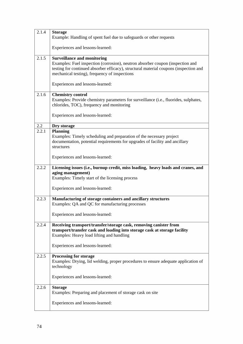
74
2.1.4 Storage Example: Handling of spent fuel due to safeguards or other requests Experiences and lessons-learned:
2.1.5 Surveillance and monitoring Examples: Fuel inspection (corrosion), neutron absorber coupon (inspection and testing for continued absorber efficacy), structural material coupons (inspection and mechanical testing), frequency of inspections Experiences and lessons-learned:
2.1.6 Chemistry control Examples: Provide chemistry parameters for surveillance (i.e., fluorides, sulphates, chlorides, TOC), frequency and monitoring Experiences and lessons-learned:
2.2 Dry storage 2.2.1 Planning
Examples: Timely scheduling and preparation of the necessary project documentation, potential requirements for upgrades of facility and ancillary structures Experiences and lessons-learned:
2.2.2 Licensing issues (i.e., burnup credit, miss loading, heavy loads and cranes, and aging management) Examples: Timely start of the licensing process Experiences and lessons-learned:
2.2.3 Manufacturing of storage containers and ancillary structures Examples: QA and QC for manufacturing processes Experiences and lessons-learned:
2.2.4 Receiving transport/transfer/storage cask, removing canister from transport/transfer cask and loading into storage cask at storage facility Examples: Heavy load lifting and handling Experiences and lessons-learned:
2.2.5 Processing for storage Examples: Drying, lid welding, proper procedures to ensure adequate application of technology Experiences and lessons-learned:
2.2.6 Storage Examples: Preparing and placement of storage cask on site Experiences and lessons-learned:

75
2.2.7 Surveillance and monitoring Examples: pressure, leak tightness, radiation doses, temperature Experiences and lessons-learned:

76
ANNEX II
2nd Questionnaire on Spent Fuel Storage Currently, the majority of the IAEA Member States are not reprocessing spent fuel from the power reactors and have not yet decided on the ultimate disposition of their spent nuclear fuel. Storage is the only solution for these countries and is becoming more and more important. Spent fuel has been stored safely and effectively for several decades and confidence is high that this will continue to be the case. With storage inventories and durations increasing, issues associated with long-term storage require more attention. A method of supporting reliable spent fuel storage is to review storage facility operations and to share information among the IAEA Member States, highlighting best practices to apply and what to avoid.
The IAEA convened consultants’ and technical meetings to develop a questionnaire for use in gathering spent fuel storage information from Member states and compilation into a technical document. The discussions ranged from very specific information to general statements on spent fuel storage. Unfortunately, given the scattering of experiences over such a wide topic, it has been very difficult to complete the document. The consultants at the most recent meeting suggested narrowing the scope of the document to a general discussion to focus on best practices. This questionnaire was developed to gather best practices from Member states with significant experience in spent fuel storage.
When completing the questionnaire, please take into account different reactor designs and provide high-level statements related to general issues of spent fuel storage operations that would be applicable to a broad spectrum of Member states. When considering your responses, evaluate what your facility or licensee has completed and what, if anything, could have been done differently. Additionally, for any issues that have been previously reported, and the documentation is publicly available, please provide the reference.
Any information gathered for this document will be compiled by the secretariat and will be generic without specific references to plants, organizations or countries.
Part I – Wet storage 1.0 Spent fuel handling Examples: During the lifetime of the spent fuel pool, there are numerous fuel handling movements that take place, some due to modifications of the pool and some due to extended storage times. Include suggestions for improvements that might minimize fuel handling events; improve positive identification of fuel assemblies; ensure secure connection between crane and assembly; minimize poor visibility and/or gas generation due to various chemical interactions, or incompatibility of various materials; and minimize potential miss loading problems.

77
2.0 Storage 2.1 Surveillance and monitoring
Example: Different methods have been developed for monitoring of fuel and pool components during storage. Please describe best practices used to evaluate physical and material characteristics; and frequency of inspections of spent fuel and pool components
2.2 Chemistry control Examples: The importance of chemistry control of the pool water is not always stated in plant safety cases, however, it is important for operators to understand why this is important and the consequences of not controlling the pool chemistry within specified limits. Please describe practices used to control spent fuel pool water chemistry to minimize fuel and pool material degradation/corrosion which might lead to fuel handling and storage issues.
3.1 Planning and implementation of pool modification Examples: The re-racking process may involve extensive fuel reshuffling; increasing spent fuel pool cooling capacity; underwater cutting and welding; and heavy load transfer. Please provide best practices used to minimize miss loading, damage to pool or spent fuel; and improve the implementation process.
3.2 Modifications to fuel handling system Examples: Modifications may include more precise and reliable fuel handling systems. Please describe best practices for modifying fuel handling systems, increasing precision of fuel movement and minimizing human error.
3.3 Repairs Examples: Repairs might include eliminating leakage from the pool liner and refurbishment of the storage racks. Please describe practices which have increased efficiency of repairs.

78
4.0 Planning and licensing issues Examples: Planning and licensing of plant modifications require significant planning ahead to generate an orderly project. Please provide advice on optimization of project planning and licensing, including dose minimization; timely scheduling and preparation of the necessary project documentation; potential requirements for upgrades; application of actual fuel conditions and operation; administrative procedures for burnup credit, high burnup and MOX fuel.
Part II – Dry storage 1.1 Planning and licensing issues Examples: Planning and licensing a dry storage facility requires significant planning ahead to complete the project to ensure sufficient storage capacity. Please provide advice on optimization of scheduling and preparation of the necessary project documentation; potential facility upgrades; and ensuring that the cask is compatible with facility structure and lifting capability.
1.2 Fuel handling issues and processing of storage casks Examples: Loading spent fuel and processing prior to placement into storage entails many operations. Please provide advice on best practices used during loading and optimizing fuel movement and its location; drying and lid welding; procedures to ensure adequate application of technology; and placement into storage.
1.3 Storage surveillance and monitoring Examples: Surveillance during dry storage varies depending on design and inventory. Please discuss surveillance and monitoring performed during storage for parameters such as pressure, leak tightness, radiation doses, temperature, etc.

79
CONTRIBUTORS TO DRAFTING AND REVIEW
Barnabas, I Public Agency for Radioactive Waste Management (PURAM), Hungary
Beaudoin, R Atomic Energy Canada Limited (AECL), Canada
Catoire, J Tractebel Engineering, Belgium
Courtois, R.J.C Tractebel Engineering, Belgium
Hofer, E Nordostschweizerische Kraftwerke AG (NOK), Switzerland
Ki-Seog, S Korea Atomic Energy Research Institute (KAERI), Republic of Korea
Kurincic, B Nuklearna Elektrana Krško (NEK), Slovenia
Lian, J Atomic Energy Canada Limited (AECL), Canada
Liao, Z Qinshan Nuclear Power Company (QNPC), China
Lovasic, Z International Atomic Energy Agency
McKay, I Sellafield Ltd., United Kingdom
Ördögh, M SOM Systems Ltd. (SOM), Hungary
Saegusa, T Central Research Institute of Electric Power Industry (CRIEPI), Japan
Schelbert, M Nordostschweizerische Kraftwerke AG (NOK), Switzerland
Standring, P Sellafield Ltd., United Kingdom
Takáts, F TS ENERCON Kft. International Consulting, Hungary
Vaclav, J Nuclear Regulatory Authority for the Slovak Republic (NRAS), Slovakia
Vegvari, I Hungarian Atomic Energy Authority (HAEA), Hungary
White, B US Nuclear Regulatory Commission (US NRC), United States of America
Yook, D Korea Institute of Nuclear Safety (KINS), Republic of Korea
Zaitsev, V Chernobyl Nuclear Power Plant, Ukraine
Zou, X International Atomic Energy Agency
Consultancy Meeting
Vienna, Austria: 10–12 December 2007 Vienna, Austria: 18–20 May 2009 Vienna, Austria: 9–11 March 2010
Vienna, Austria: 10–12 December 2011
Technical Meeting
Vienna, Austria: 13–16 October 2008


@ No. 23
ORDERING LOCALLYIn the following countries, IAEA priced publications may be purchased from the sources listed below, or from major local booksellers. Orders for unpriced publications should be made directly to the IAEA. The contact details are given at the end of this list.
AUSTRALIADA Information Services648 Whitehorse Road, Mitcham, VIC 3132, AUSTRALIA Telephone: +61 3 9210 7777 Fax: +61 3 9210 7788 Email: [email protected] Web site: http://www.dadirect.com.au
BELGIUMJean de LannoyAvenue du Roi 202, 1190 Brussels, BELGIUM Telephone: +32 2 5384 308 Fax: +61 2 5380 841 Email: [email protected] Web site: http://www.jean-de-lannoy.be
CANADARenouf Publishing Co. Ltd.Telephone: +1 613 745 2665 Fax: +1 643 745 7660 5369 Canotek Road, Ottawa, ON K1J 9J3, CANADA Email: [email protected] Web site: http://www.renoufbooks.com
Bernan Associates4501 Forbes Blvd., Suite 200, Lanham, MD 20706-4391, USA Telephone: +1 800 865 3457 Fax: +1 800 865 3450 Email: [email protected] Web site: http://www.bernan.com
CZECH REPUBLICSuweco CZ, spol. S.r.o.Klecakova 347, 180 21 Prague 9, CZECH REPUBLIC Telephone: +420 242 459 202 Fax: +420 242 459 203 Email: [email protected] Web site: http://www.suweco.cz
FINLANDAkateeminen KirjakauppaPO Box 128 (Keskuskatu 1), 00101 Helsinki, FINLAND Telephone: +358 9 121 41 Fax: +358 9 121 4450 Email: [email protected] Web site: http://www.akateeminen.com
FRANCEForm-Edit5, rue Janssen, PO Box 25, 75921 Paris CEDEX, FRANCE Telephone: +33 1 42 01 49 49 Fax: +33 1 42 01 90 90 Email: [email protected] Web site: http://www.formedit.fr
Lavoisier SAS14, rue de Provigny, 94236 Cachan CEDEX, FRANCE Telephone: +33 1 47 40 67 00 Fax: +33 1 47 40 67 02 Email: [email protected] Web site: http://www.lavoisier.fr
L’Appel du livre99, rue de Charonne, 75011 Paris, FRANCE Telephone: +33 1 43 07 50 80 Fax: +33 1 43 07 50 80 Email: [email protected] Web site: http://www.appeldulivre.fr
GERMANYGoethe Buchhandlung Teubig GmbHSchweitzer Fachinformationen Willstaetterstrasse 15, 40549 Duesseldorf, GERMANY Telephone: +49 (0) 211 49 8740 Fax: +49 (0) 211 49 Email: [email protected] Web site: http://www. http://www.goethebuch.de/
HUNGARYLibrotade Ltd., Book ImportPF 126, 1656 Budapest, HUNGARY Telephone: +36 1 257 7777 Fax: +36 1 257 7472 Email: [email protected] Web site: http://www.librotade.hu

INDIAAllied Publishers1st Floor, Dubash House, 15, J.N. Heredi Marg Ballard Estate, Mumbai 400001, INDIA Telephone: +91 22 2261 7926/27 Fax: +91 22 2261 7928 Email: [email protected] Web site: http://www.alliedpublishers.com
Bookwell3/79 Nirankari, Dehli 110009, INDIA Tel.: +91 11 2760 1283 +91 11 27604536 Email: [email protected] Web site: http://www.bookwellindia.com/
ITALYLibreria Scientifica “AEIOU”Via Vincenzo Maria Coronelli 6, 20146 Milan, ITALY Tel.: +39 02 48 95 45 52 Fax: +39 02 48 95 45 48 Email: [email protected] Web site: http://www.libreriaaeiou.eu/
JAPANMaruzen Co., Ltd.1-9-18 Kaigan, Minato-ku, Tokyo 105-0022, JAPAN Tel.: +81 3 6367 6047 Fax: +81 3 6367 6160 Email: [email protected] Web site: http://maruzen.co.jp
NETHERLANDSMartinus Nijhoff InternationalKoraalrood 50, Postbus 1853, 2700 CZ Zoetermeer, NETHERLANDS Tel.: +31 793 684 400 Fax: +31 793 615 698 Email: [email protected] Web site: http://www.nijhoff.nl
Swets PO Box 26, 2300 AA Leiden Dellaertweg 9b, 2316 WZ Leiden, NETHERLANDS Telephone: +31 88 4679 263 Fax: +31 88 4679 388 Email: [email protected] Web site: www.swets.com
SLOVENIACankarjeva Zalozba ddKopitarjeva 2, 1515 Ljubljana, SLOVENIA Tel.: +386 1 432 31 44 Fax: +386 1 230 14 35 Email: [email protected] Web site: http://www.mladinska.com/cankarjeva_zalozba
SPAINDiaz de Santos, S.A.Librerias Bookshop Departamento de pedidos Calle Albasanz 2, esquina Hermanos Garcia Noblejas 21, 28037 Madrid, SPAIN Telephone: +34 917 43 48 90 Email: [email protected] Web site: http://www.diazdesantos.es/
UNITED KINGDOMThe Stationery Office Ltd. (TSO)PO Box 29, Norwich, Norfolk, NR3 1PD, UNITED KINGDOM Telephone: +44 870 600 5552 Email (orders): [email protected] (enquiries): [email protected] Web site: http://www.tso.co.uk
On-line orders:DELTA International Ltd.39, Alexandra Road, Addlestone, Surrey, KT15 2PQ, UNITED KINGDOM Email: [email protected] Web site: http://www.profbooks.com
United Nations (UN)300 East 42nd Street, IN-919J, New York, NY 1001, USA Telephone: +1 212 963 8302 Fax: 1 212 963 3489 Email: [email protected] Web site: http://www.unp.un.org
UNITED STATES OF AMERICABernan Associates4501 Forbes Blvd., Suite 200, Lanham, MD 20706-4391, USA Tel.: +1 800 865 3457 Fax: +1 800 865 3450 Email: [email protected] Web site: http://www.bernan.com
Renouf Publishing Co. Ltd.812 Proctor Avenue, Ogdensburg, NY 13669, USA Tel.: +800 551 7470 (toll free) +800 568 8546 (toll free) Email: [email protected] Web site: http://www.renoufbooks.com
Orders for both priced and unpriced publications may be addressed directly to:IAEA Publishing Section, Marketing and Sales Unit, International Atomic Energy Agency Vienna International Centre, PO Box 100, 1400 Vienna, Austria Telephone: +43 1 2600 22529 or 22488 • Fax: +43 1 2600 29302 Email: [email protected] • Web site: http://www.iaea.org/books


13-42111

International Atomic Energy AgencyVienna
ISBN 978–92–0–113813–2ISSN 1011–4289
Spent Fuel Storage Operation —
Lessons LearnedIAEA TECD
OC 1725