x-plane 11
TRANSCRIPT
1
X-Plane 11 Cirrus SF50
Pilot’s Operating Manual Author: Julian Lockwood ([email protected])
Copyright: Laminar Research 2020
Disclaimer The information contained in this document is for simulation use only, within the X-Plane flight simulator. This document is not subject to revision and has not been checked for accuracy. This document is intended for entertainment only and may not to be used in situations involving real-life aircraft, or real-life aviation.
Distribution
This document may be copied and distributed by Laminar Research customers and developers, for entertainment. It may also be distributed with third-party content developed for X-Plane 11.
2
Contents Background: The Cirrus SF50 ................................................................................................................... 4
Cirrus SF50 Specifications .................................................................................................................... 5
The X-Plane SF50 ..................................................................................................................................... 6
Views and Controls .................................................................................................................................. 7
Creating “Quick Look” views ................................................................................................................ 8
Operating the controls ....................................................................................................................... 11
Assigning peripheral devices .............................................................................................................. 13
A Tour of the Cockpit ............................................................................................................................. 15
Overhead Panel ................................................................................................................................. 15
Display Panels .................................................................................................................................... 16
Primary Flight Display (PFD) ........................................................................................................... 16
Multi-Function Display (MFD) ........................................................................................................ 17
Audio Panel Display ....................................................................................................................... 17
Weight and Balance Display ........................................................................................................... 18
Systems Display ............................................................................................................................. 18
[PFD] Controls & Features.................................................................................................................. 19
[MFD] Controls & Features ................................................................................................................ 24
Center Pedestal ................................................................................................................................. 28
Thrust Lever................................................................................................................................... 28
Flap Lever ...................................................................................................................................... 29
Fuel Control Switch ........................................................................................................................ 29
Autopilot Control Panel ................................................................................................................. 30
Autopilot Operation .............................................................................................................................. 31
ILS Approach...................................................................................................................................... 33
Set the Nav1 or Nav2 frequency for the ILS approach .................................................................... 33
The Course Deviation Indicator (CDI) ............................................................................................. 34
The Glide Slope Indicator and Vertical Speed Pointer ..................................................................... 34
Autopilot Assisted ILS Approach ..................................................................................................... 35
Flight Planning ....................................................................................................................................... 36
Fuel Calculation ..................................................................................................................................... 37
Load Sheet Tables.................................................................................................................................. 37
PAYLOAD: EMPTY .............................................................................................................................. 38
3
PAYLOAD: MEDIUM ........................................................................................................................... 38
PAYLOAD: FULL .................................................................................................................................. 38
Setting the Weight, Balance and Fuel in X-Plane ................................................................................ 39
Checklists .............................................................................................................................................. 40
Pre-Flight Exterior Inspection ............................................................................................................. 40
Cold and Dark to Engine Start ............................................................................................................ 42
Before Taxi ........................................................................................................................................ 46
Before Takeoff ................................................................................................................................... 49
After Takeoff ..................................................................................................................................... 50
Cruise ................................................................................................................................................ 52
Before Landing .................................................................................................................................. 53
Landing.............................................................................................................................................. 54
After Landing ..................................................................................................................................... 55
Parking .............................................................................................................................................. 57
4
Background: The Cirrus SF50
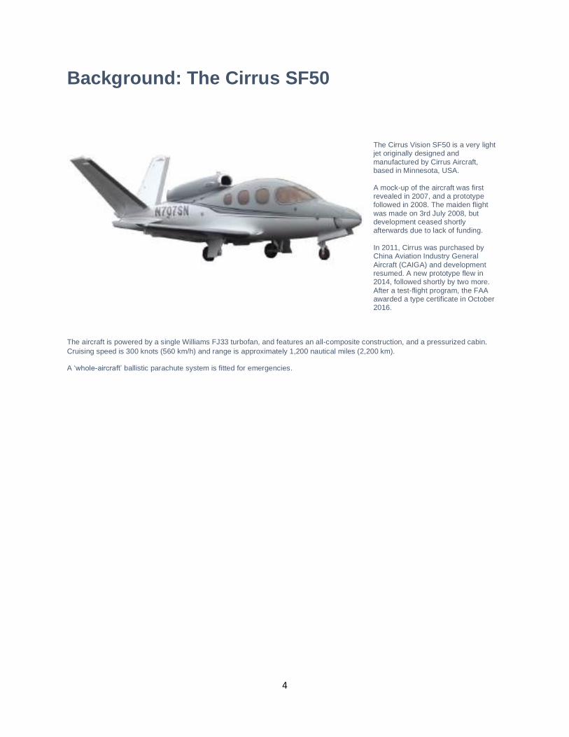
The Cirrus Vision SF50 is a very light jet originally designed and manufactured by Cirrus Aircraft, based in Minnesota, USA. A mock-up of the aircraft was first revealed in 2007, and a prototype followed in 2008. The maiden flight was made on 3rd July 2008, but development ceased shortly afterwards due to lack of funding. In 2011, Cirrus was purchased by China Aviation Industry General Aircraft (CAIGA) and development resumed. A new prototype flew in 2014, followed shortly by two more. After a test-flight program, the FAA awarded a type certificate in October 2016.
The aircraft is powered by a single Williams FJ33 turbofan, and features an all-composite construction, and a pressurized cabin. Cruising speed is 300 knots (560 km/h) and range is approximately 1,200 nautical miles (2,200 km).
A ‘whole-aircraft’ ballistic parachute system is fitted for emergencies.
5
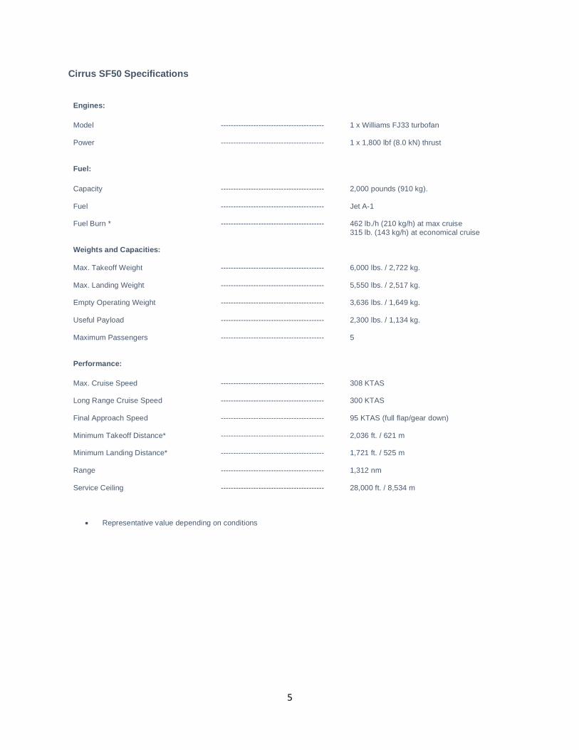
Cirrus SF50 Specifications
Engines:
Model ----------------------------------------- 1 x Williams FJ33 turbofan
Power ----------------------------------------- 1 x 1,800 lbf (8.0 kN) thrust
Fuel:
Capacity ----------------------------------------- 2,000 pounds (910 kg).
Fuel ----------------------------------------- Jet A-1
Fuel Burn * ----------------------------------------- 462 lb./h (210 kg/h) at max cruise 315 lb. (143 kg/h) at economical cruise
Weights and Capacities:
Max. Takeoff Weight ----------------------------------------- 6,000 lbs. / 2,722 kg.
Max. Landing Weight ----------------------------------------- 5,550 lbs. / 2,517 kg.
Empty Operating Weight ----------------------------------------- 3,636 lbs. / 1,649 kg.
Useful Payload ----------------------------------------- 2,300 lbs. / 1,134 kg.
Maximum Passengers ----------------------------------------- 5
Performance:
Max. Cruise Speed ----------------------------------------- 308 KTAS
Long Range Cruise Speed ----------------------------------------- 300 KTAS
Final Approach Speed ----------------------------------------- 95 KTAS (full flap/gear down)
Minimum Takeoff Distance* ----------------------------------------- 2,036 ft. / 621 m
Minimum Landing Distance* ----------------------------------------- 1,721 ft. / 525 m
Range ----------------------------------------- 1,312 nm
Service Ceiling ----------------------------------------- 28,000 ft. / 8,534 m
• Representative value depending on conditions
6
The X-Plane SF50
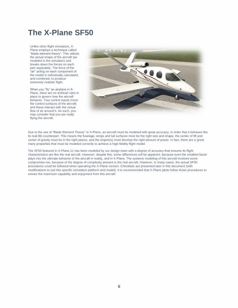
Unlike other flight simulators, X-Plane employs a technique called “blade element theory”. This utilizes the actual shape of the aircraft (as modeled in the simulator) and breaks down the forces on each part separately. The force of the “air” acting on each component of
the model is individually calculated, and combined, to produce extremely realistic flight. When you “fly” an airplane in X-Plane, there are no artificial rules in place to govern how the aircraft behaves. Your control inputs move the control surfaces of the aircraft, and these interact with the virtual flow of air around it. As such, you may consider that you are really flying the aircraft.
Due to the use of “Blade Element Theory” in X-Plane, an aircraft must be modeled with great accuracy, in order that it behaves like its real-life counterpart. This means the fuselage, wings and tail surfaces must be the right size and shape, the center of lift and center of gravity must be in the right places, and the engine(s) must develop the right amount of power. In fact, there are a great many properties that must be modeled correctly to achieve a high-fidelity flight model.
The SF50 featured in X-Plane-11 has been modeled by our design team with a degree of accuracy that ensures its flight characteristics are like the real aircraft. However, despite this, some differences will be apparent, because even the smallest factor plays into the ultimate behavior of the aircraft in reality, and in X-Plane. The systems modeling of this aircraft involves some compromise too, because of the degree of complexity present in the real aircraft. However, in many cases, the actual SF50 procedures could be followed when operating the X-Plane version. Checklists are presented later in this document (with modifications to suit this specific simulation platform and model). It is recommended that X-Plane pilots follow those procedures to extract the maximum capability and enjoyment from this aircraft.
7
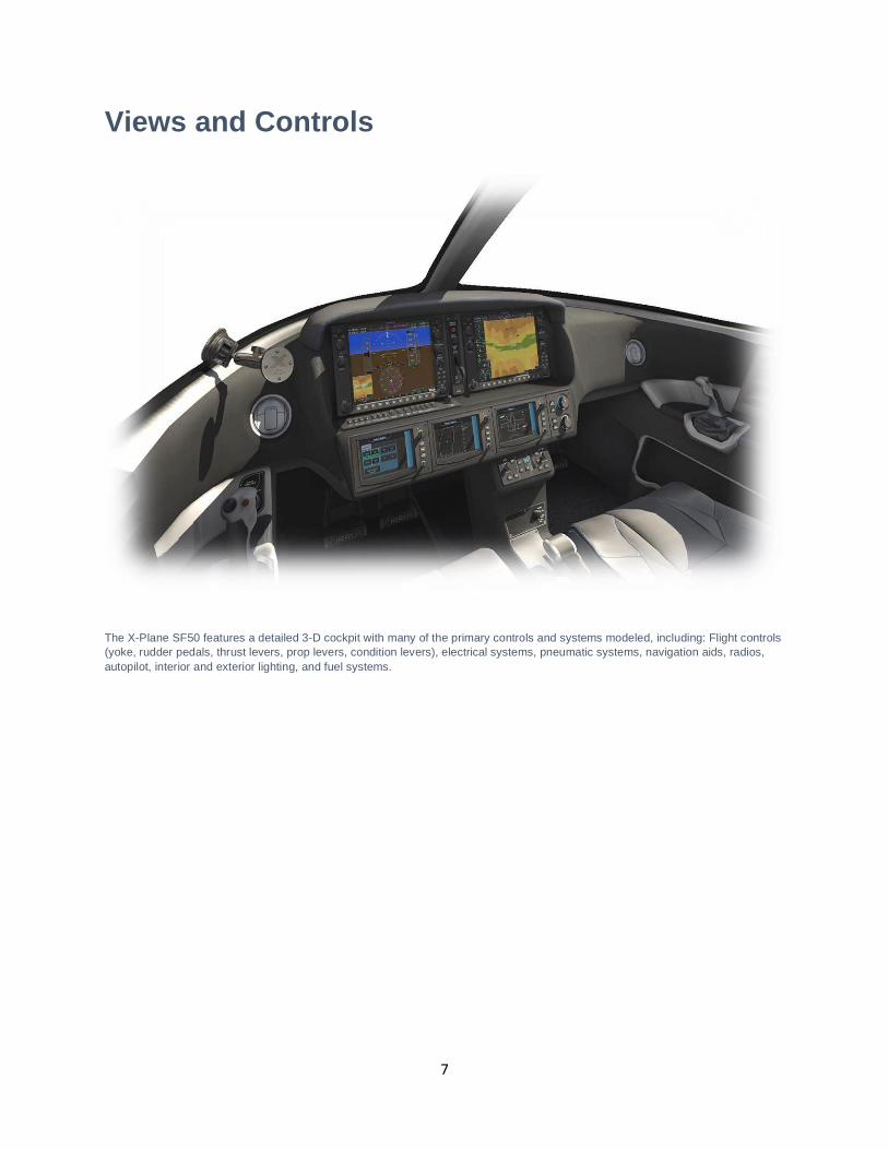
Views and Controls
The X-Plane SF50 features a detailed 3-D cockpit with many of the primary controls and systems modeled, including: Flight controls (yoke, rudder pedals, thrust levers, prop levers, condition levers), electrical systems, pneumatic systems, navigation aids, radios, autopilot, interior and exterior lighting, and fuel systems.
8
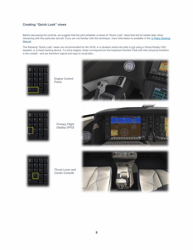
Creating “Quick Look” views
Before discussing the controls, we suggest that the pilot establish a series of “Quick Look” views that will be helpful later when interacting with this particular aircraft. If you are not familiar with this technique, more information is available in the X-Plane Desktop Manual. The following “Quick Look” views are recommended for the SF50, in a situation where the pilot is not using a Virtual Reality (VR) headset, or a head tracking device. To some degree, these correspond (on the keyboard Number Pad) with their physical locations in the cockpit - and are therefore logical and easy to recall later.
Engine Control Panel
Primary Flight Display (PFD)
Thrust Lever and Center Console
9
Multi-Function Display (MFD)
Pilot’s View Forward
Systems Panel & Autopilot
Co-Pilot’s View Forward
10
Left Glance View
Overhead Panel
Right Glance View
11
Operating the controls
This section covers the basic techniques for the operation of the controls that you will encounter in the cockpit of an X-Plane aircraft. Control manipulators are consistent across all X-Plane 11 aircraft. However, the specific illustrations in THIS chapter may differ from YOUR aircraft.
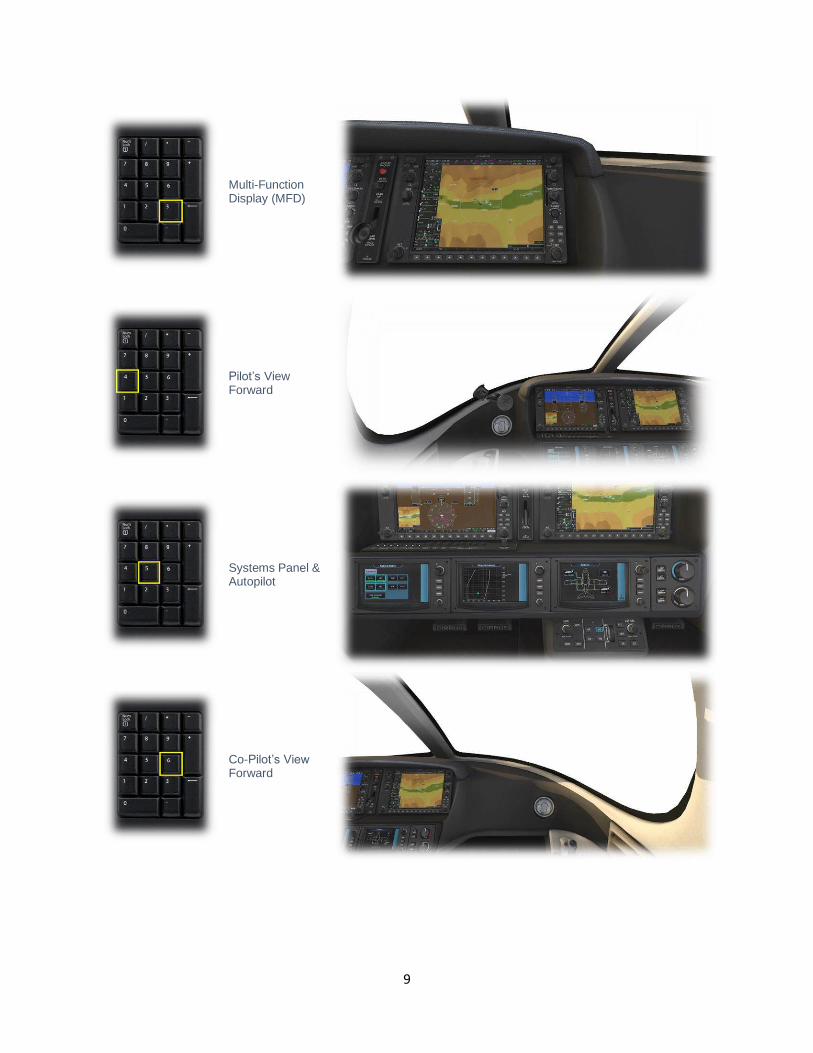
Toggle and Rocker switches are operated with a single click of the mouse. Place the mouse pointer slightly above, or below, the center point of the switch, depending on the direction you intend to move it. A small white arrow is displayed to confirm the intended direction. Click the mouse button to complete the operation.
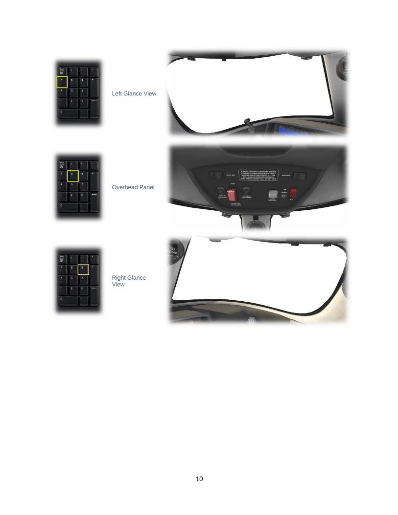
Levers are operated by assigning a peripheral device to the necessary axes in X-Plane (throttle, prop, mixture etc.). More information is available in the X-Plane Desktop Manual. Levers may also be operated by clicking and dragging the mouse pointer.
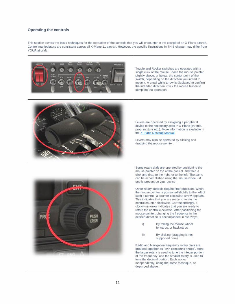
Some rotary dials are operated by positioning the mouse pointer on top of the control, and then a click and drag to the right, or to the left. The same can be accomplished using the mouse wheel - if one is present on your device. Other rotary controls require finer precision. When the mouse pointer is positioned slightly to the left of such a control, a counter-clockwise arrow appears. This indicates that you are ready to rotate the control counter-clockwise. Correspondingly, a clockwise arrow indicates that you are ready to rotate the control clockwise. After positioning the mouse pointer, changing the frequency in the desired direction is accomplished in two ways:
i) By rolling the mouse wheel forwards, or backwards
ii) By clicking (dragging is not
supported here) Radio and Navigation frequency rotary dials are grouped together as “twin concentric knobs”. Here, the larger rotary is used to tune the integer portion of the frequency, and the smaller rotary is used to tune the decimal portion. Each works independently, using the same technique, as described above.
12
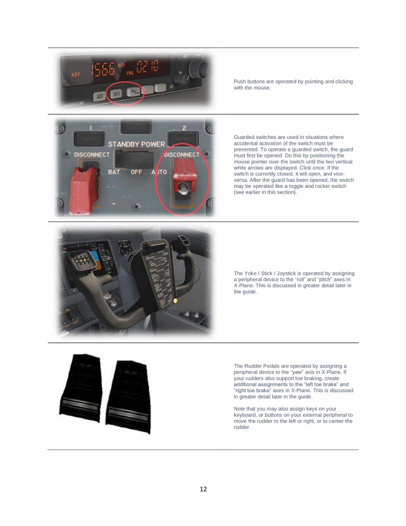
Push buttons are operated by pointing and clicking with the mouse.
Guarded switches are used in situations where accidental activation of the switch must be prevented. To operate a guarded switch, the guard must first be opened. Do this by positioning the mouse pointer over the switch until the two vertical white arrows are displayed. Click once. If the switch is currently closed, it will open, and vice-versa. After the guard has been opened, the switch may be operated like a toggle and rocker switch (see earlier in this section).
The Yoke / Stick / Joystick is operated by assigning a peripheral device to the “roll” and “pitch” axes in X-Plane. This is discussed in greater detail later in the guide.
The Rudder Pedals are operated by assigning a peripheral device to the “yaw” axis in X-Plane. If your rudders also support toe braking, create additional assignments to the “left toe brake” and “right toe brake” axes in X-Plane. This is discussed in greater detail later in the guide. Note that you may also assign keys on your keyboard, or buttons on your external peripheral to move the rudder to the left or right, or to center the rudder.
13
Assigning peripheral devices
This section of the manual deals with an “ideal” scenario, in terms of the assignment of external computer peripherals to operate the X-Plane SF50 with the highest degree of realism. If you are missing some of these external peripherals, you may elect to choose a different configuration that better suits your hardware.
More information is available in the X-Plane Desktop Manual.
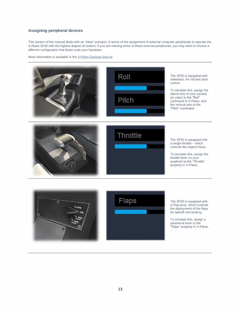
The SF50 is equipped with sidesticks, for roll and pitch control. To simulate this, assign the lateral axis of your joystick (or yoke) to the “Roll” command in X-Plane, and the vertical axis to the “Pitch” command.
The SF50 is equipped with a single throttle – which controls the engine thrust. To simulate this, assign the throttle lever on your quadrant to the “Throttle” property in X-Plane.
The SF50 is equipped with a Flap lever, which controls the deployment of the flaps for takeoff and landing. To simulate this, assign a peripheral lever to the “Flaps” property in X-Plane. .
14
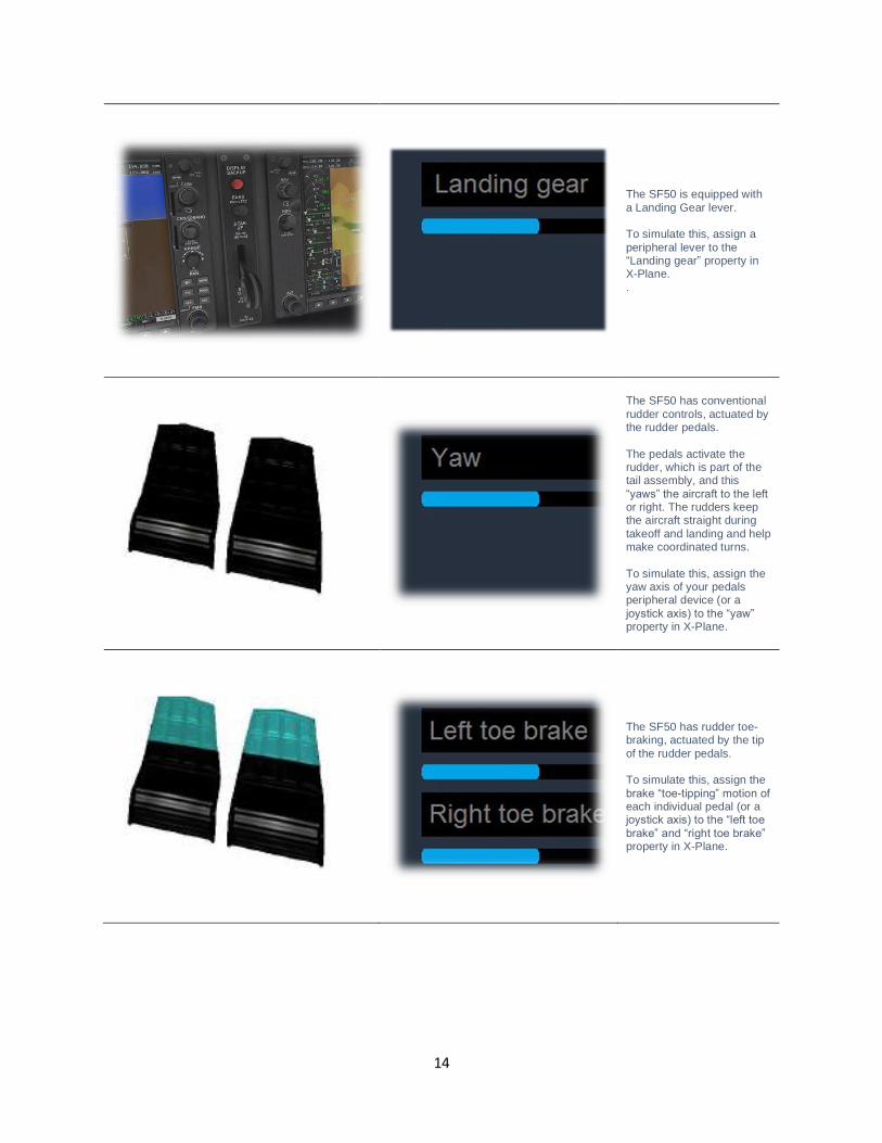
The SF50 is equipped with a Landing Gear lever. To simulate this, assign a peripheral lever to the “Landing gear” property in X-Plane. .
The SF50 has conventional rudder controls, actuated by the rudder pedals. The pedals activate the rudder, which is part of the tail assembly, and this “yaws” the aircraft to the left or right. The rudders keep the aircraft straight during takeoff and landing and help make coordinated turns. To simulate this, assign the yaw axis of your pedals peripheral device (or a joystick axis) to the “yaw” property in X-Plane.
The SF50 has rudder toe-braking, actuated by the tip of the rudder pedals. To simulate this, assign the brake “toe-tipping” motion of each individual pedal (or a joystick axis) to the “left toe
brake” and “right toe brake” property in X-Plane.
15
A Tour of the Cockpit
In this section of the manual, the cockpit will be broken down into distinct functional areas, and the controls that are featured in those areas will be identified and described. This will assist in locating the necessary instruments and controls later, when working through the aircraft check lists, and flying the aircraft.
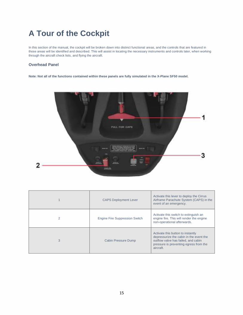
Overhead Panel
Note: Not all of the functions contained within these panels are fully simulated in the X-Plane SF50 model.
1 CAPS Deployment Lever
Activate this lever to deploy the Cirrus Airframe Parachute System (CAPS) in the event of an emergency.
2 Engine Fire Suppression Switch
Activate this switch to extinguish an engine fire. This will render the engine non-operational afterwards.
3 Cabin Pressure Dump
Activate this button to instantly depressurize the cabin in the event the outflow valve has failed, and cabin pressure is preventing egress from the aircraft.
16
Display Panels
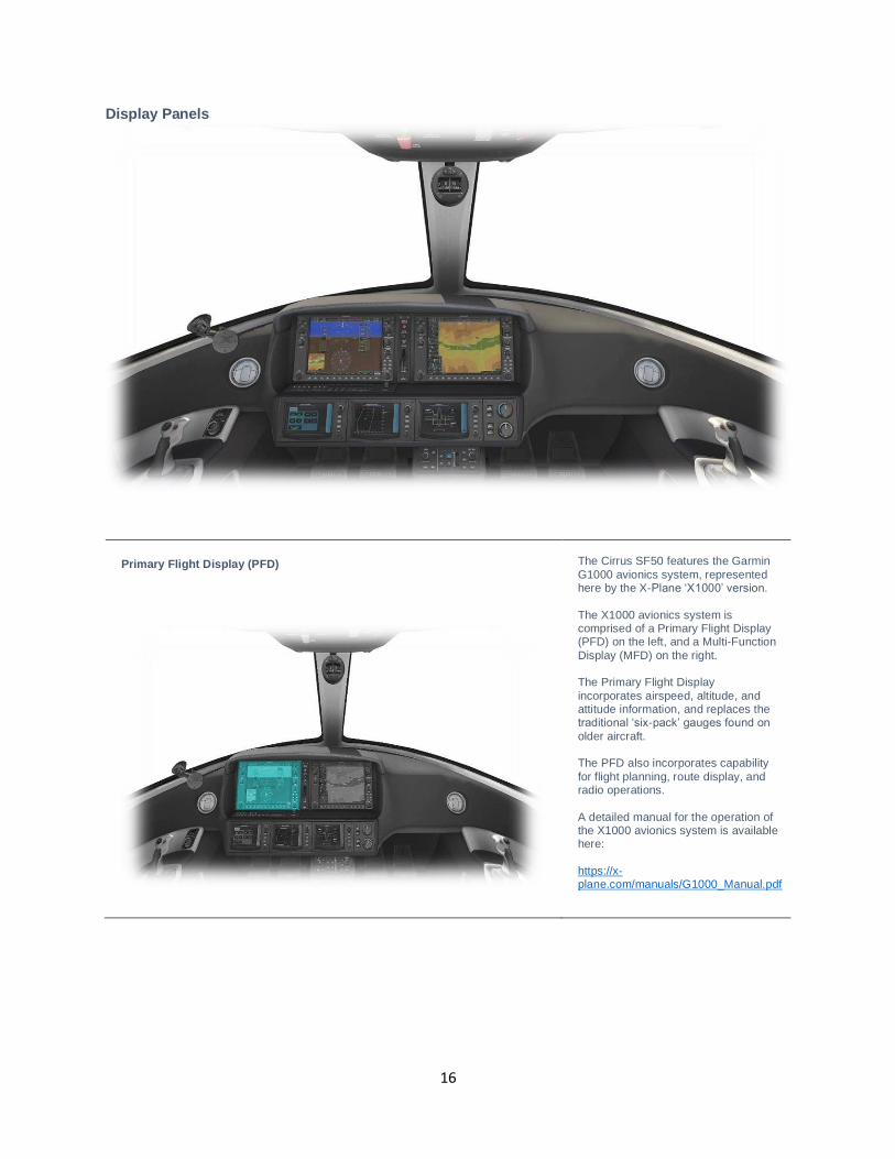
Primary Flight Display (PFD)
The Cirrus SF50 features the Garmin G1000 avionics system, represented here by the X-Plane ‘X1000’ version. The X1000 avionics system is comprised of a Primary Flight Display (PFD) on the left, and a Multi-Function Display (MFD) on the right. The Primary Flight Display incorporates airspeed, altitude, and attitude information, and replaces the traditional ‘six-pack’ gauges found on
older aircraft. The PFD also incorporates capability for flight planning, route display, and radio operations. A detailed manual for the operation of the X1000 avionics system is available here: https://x-plane.com/manuals/G1000_Manual.pdf
17
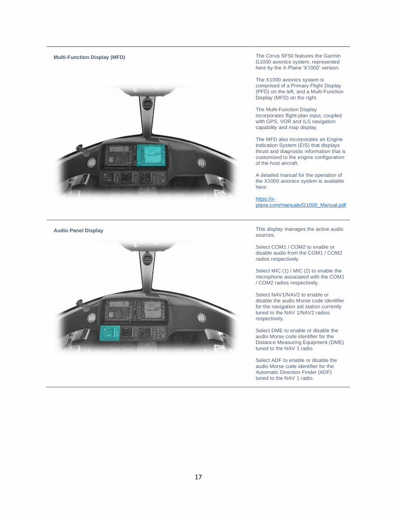
Multi-Function Display (MFD)
The Cirrus SF50 features the Garmin G1000 avionics system, represented here by the X-Plane ‘X1000’ version. The X1000 avionics system is comprised of a Primary Flight Display (PFD) on the left, and a Multi-Function Display (MFD) on the right. The Multi-Function Display incorporates flight-plan input, coupled with GPS, VOR and ILS navigation capability and map display. The MFD also incorporates an Engine Indication System (EIS) that displays thrust and diagnostic information that is customized to the engine configuration of the host aircraft. A detailed manual for the operation of the X1000 avionics system is available here: https://x-plane.com/manuals/G1000_Manual.pdf
Audio Panel Display
This display manages the active audio sources. Select COM1 / COM2 to enable or disable audio from the COM1 / COM2 radios respectively. Select MIC (1) / MIC (2) to enable the microphone associated with the COM1 / COM2 radios respectively. Select NAV1/NAV2 to enable or disable the audio Morse code identifier for the navigation aid station currently tuned to the NAV 1/NAV2 radios respectively. Select DME to enable or disable the audio Morse code identifier for the Distance Measuring Equipment (DME) tuned to the NAV 1 radio. Select ADF to enable or disable the audio Morse code identifier for the Automatic Direction Finder (ADF) tuned to the NAV 1 radio.
18
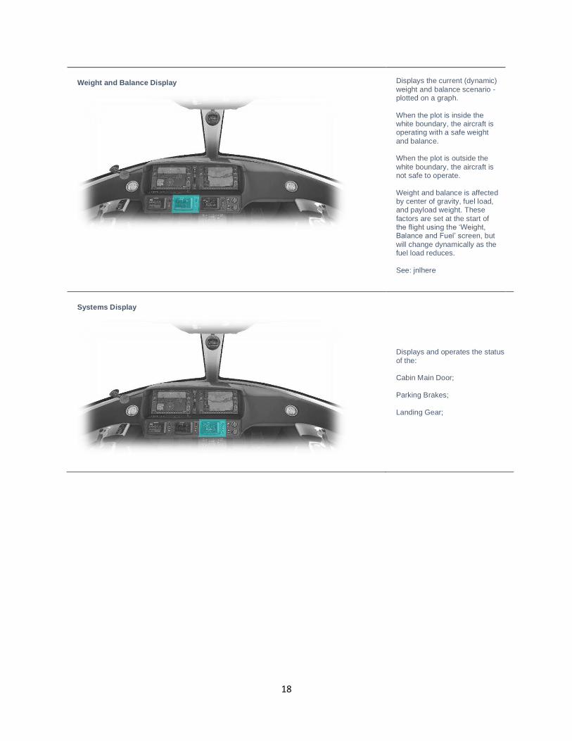
Weight and Balance Display
Displays the current (dynamic) weight and balance scenario - plotted on a graph. When the plot is inside the white boundary, the aircraft is operating with a safe weight and balance. When the plot is outside the white boundary, the aircraft is not safe to operate. Weight and balance is affected by center of gravity, fuel load, and payload weight. These factors are set at the start of the flight using the ‘Weight, Balance and Fuel’ screen, but will change dynamically as the fuel load reduces. See: jnlhere
Systems Display
Displays and operates the status of the: Cabin Main Door; Parking Brakes; Landing Gear;
19
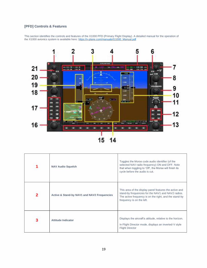
[PFD] Controls & Features
This section identifies the controls and features of the X1000 PFD (Primary Flight Display). A detailed manual for the operation of the X1000 avionics system is available here: https://x-plane.com/manuals/G1000_Manual.pdf
1 NAV Audio Squelch
Toggles the Morse code audio identifier (of the selected NAV radio frequency) ON and OFF. Note that when toggling to ‘Off’, the Morse will finish its
cycle before the audio is cut.
2 Active & Stand-by NAV1 and NAV2 Frequencies
This area of the display panel features the active and stand-by frequencies for the NAV1 and NAV2 radios. The active frequency is on the right, and the stand-by frequency is on the left.
3 Attitude Indicator
Displays the aircraft’s attitude, relative to the horizon.
In Flight Director mode, displays an inverted-V style Flight Director
20
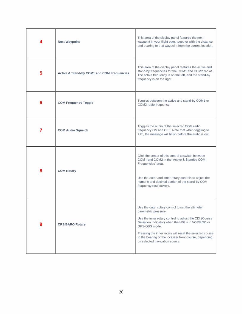
4 Next Waypoint
This area of the display panel features the next waypoint in your flight plan, together with the distance and bearing to that waypoint from the current location.
5 Active & Stand-by COM1 and COM Frequencies
This area of the display panel features the active and stand-by frequencies for the COM1 and COM2 radios. The active frequency is on the left, and the stand-by frequency is on the right.
6 COM Frequency Toggle
Toggles between the active and stand-by COM1 or COM2 radio frequency.
7 COM Audio Squelch
Toggles the audio of the selected COM radio frequency ON and OFF. Note that when toggling to ‘Off’, the message will finish before the audio is cut.
8 COM Rotary
Click the center of this control to switch between COM1 and COM2 in the ‘Active & Standby COM
Frequencies’ area.
Use the outer and inner rotary controls to adjust the numeric and decimal portion of the stand-by COM frequency respectively.
9 CRS/BARO Rotary
Use the outer rotary control to set the altimeter barometric pressure.
Use the inner rotary control to adjust the CDI (Course Deviation Indicator) when the HSI is in VOR/LOC or GPS-OBS mode.
Pressing the inner rotary will reset the selected course to the bearing or the localizer front course, depending on selected navigation source.
21
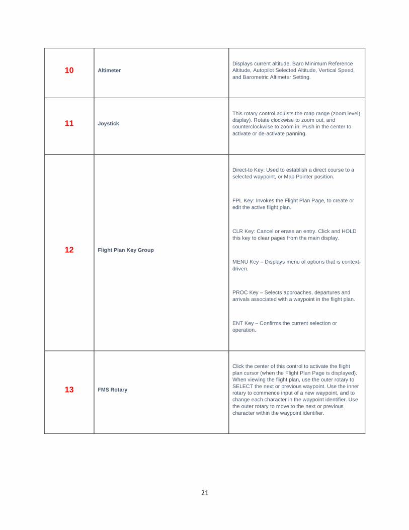
10 Altimeter
Displays current altitude, Baro Minimum Reference Altitude, Autopilot Selected Altitude, Vertical Speed, and Barometric Altimeter Setting.
11 Joystick
This rotary control adjusts the map range (zoom level) display). Rotate clockwise to zoom out, and counterclockwise to zoom in. Push in the center to activate or de-activate panning.
12 Flight Plan Key Group
Direct-to Key: Used to establish a direct course to a selected waypoint, or Map Pointer position.
FPL Key: Invokes the Flight Plan Page, to create or edit the active flight plan.
CLR Key: Cancel or erase an entry. Click and HOLD this key to clear pages from the main display.
MENU Key – Displays menu of options that is context-driven.
PROC Key – Selects approaches, departures and arrivals associated with a waypoint in the flight plan.
ENT Key – Confirms the current selection or operation.
13 FMS Rotary
Click the center of this control to activate the flight plan cursor (when the Flight Plan Page is displayed). When viewing the flight plan, use the outer rotary to SELECT the next or previous waypoint. Use the inner rotary to commence input of a new waypoint, and to change each character in the waypoint identifier. Use the outer rotary to move to the next or previous character within the waypoint identifier.
22
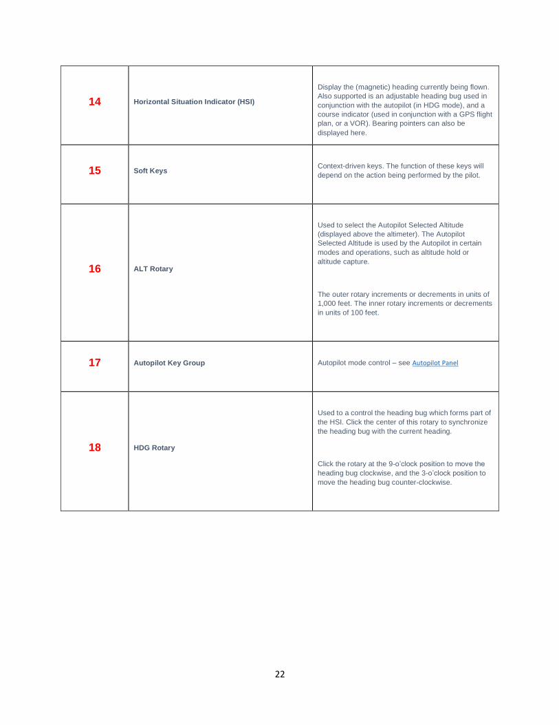
14 Horizontal Situation Indicator (HSI)
Display the (magnetic) heading currently being flown. Also supported is an adjustable heading bug used in conjunction with the autopilot (in HDG mode), and a course indicator (used in conjunction with a GPS flight plan, or a VOR). Bearing pointers can also be displayed here.
15 Soft Keys
Context-driven keys. The function of these keys will depend on the action being performed by the pilot.
16 ALT Rotary
Used to select the Autopilot Selected Altitude (displayed above the altimeter). The Autopilot Selected Altitude is used by the Autopilot in certain modes and operations, such as altitude hold or altitude capture.
The outer rotary increments or decrements in units of 1,000 feet. The inner rotary increments or decrements in units of 100 feet.
17 Autopilot Key Group
Autopilot mode control – see Autopilot Panel
18 HDG Rotary
Used to a control the heading bug which forms part of the HSI. Click the center of this rotary to synchronize the heading bug with the current heading.
Click the rotary at the 9-o’clock position to move the
heading bug clockwise, and the 3-o’clock position to
move the heading bug counter-clockwise.
23
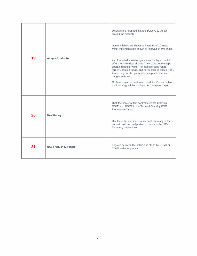
19 Airspeed Indicator
Displays the Airspeed in knots (relative to the air around the aircraft).
Numeric labels are shown at intervals of 10 knots. Minor increments are shown at intervals of five knots.
A color-coded speed range is also displayed, which differs for individual aircraft. The colors denote flaps operating range (white), normal operating range (green), caution range, and never-exceed speed (red). A red range is also present for airspeeds that are dangerously low.
On twin-engine aircraft, a red mark for VMC and a blue mark for VYSE will be displayed on the speed tape.
20 NAV Rotary
Click the center of this control to switch between COM1 and COM2 in the ‘Active & Standby COM
Frequencies’ area.
Use the outer and inner rotary controls to adjust the numeric and decimal portion of the stand-by NAV frequency respectively.
21 NAV Frequency Toggle
Toggles between the active and stand-by COM1 or COM2 radio frequency.
24
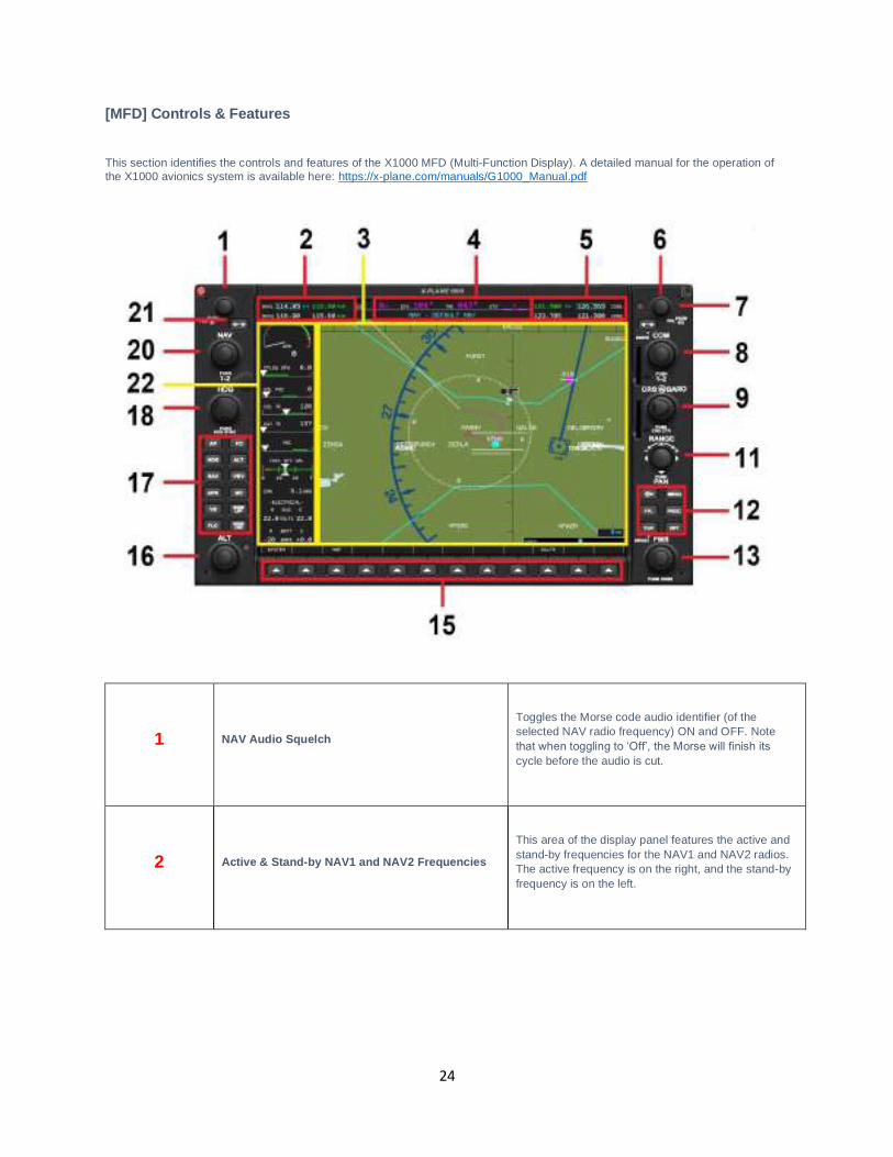
[MFD] Controls & Features
This section identifies the controls and features of the X1000 MFD (Multi-Function Display). A detailed manual for the operation of the X1000 avionics system is available here: https://x-plane.com/manuals/G1000_Manual.pdf
1 NAV Audio Squelch
Toggles the Morse code audio identifier (of the selected NAV radio frequency) ON and OFF. Note that when toggling to ‘Off’, the Morse will finish its
cycle before the audio is cut.
2 Active & Stand-by NAV1 and NAV2 Frequencies
This area of the display panel features the active and stand-by frequencies for the NAV1 and NAV2 radios. The active frequency is on the right, and the stand-by frequency is on the left.
25
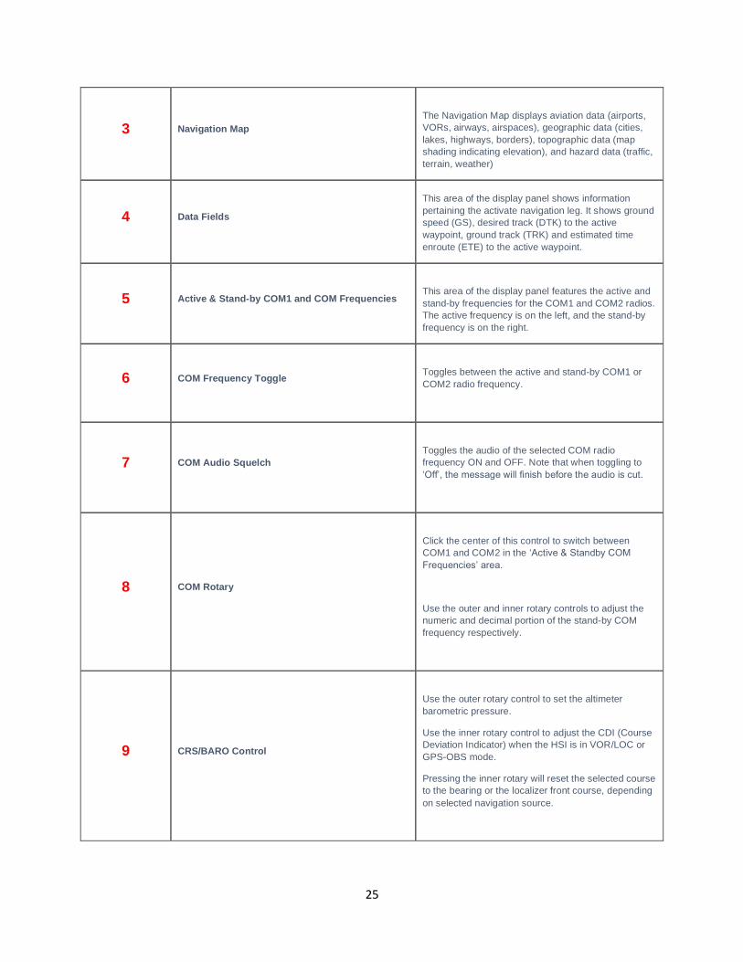
3 Navigation Map
The Navigation Map displays aviation data (airports, VORs, airways, airspaces), geographic data (cities, lakes, highways, borders), topographic data (map shading indicating elevation), and hazard data (traffic, terrain, weather)
4 Data Fields
This area of the display panel shows information pertaining the activate navigation leg. It shows ground speed (GS), desired track (DTK) to the active waypoint, ground track (TRK) and estimated time enroute (ETE) to the active waypoint.
5 Active & Stand-by COM1 and COM Frequencies
This area of the display panel features the active and stand-by frequencies for the COM1 and COM2 radios. The active frequency is on the left, and the stand-by frequency is on the right.
6 COM Frequency Toggle
Toggles between the active and stand-by COM1 or COM2 radio frequency.
7 COM Audio Squelch
Toggles the audio of the selected COM radio frequency ON and OFF. Note that when toggling to ‘Off’, the message will finish before the audio is cut.
8 COM Rotary
Click the center of this control to switch between COM1 and COM2 in the ‘Active & Standby COM
Frequencies’ area.
Use the outer and inner rotary controls to adjust the numeric and decimal portion of the stand-by COM frequency respectively.
9 CRS/BARO Control
Use the outer rotary control to set the altimeter barometric pressure.
Use the inner rotary control to adjust the CDI (Course Deviation Indicator) when the HSI is in VOR/LOC or GPS-OBS mode.
Pressing the inner rotary will reset the selected course to the bearing or the localizer front course, depending on selected navigation source.
26
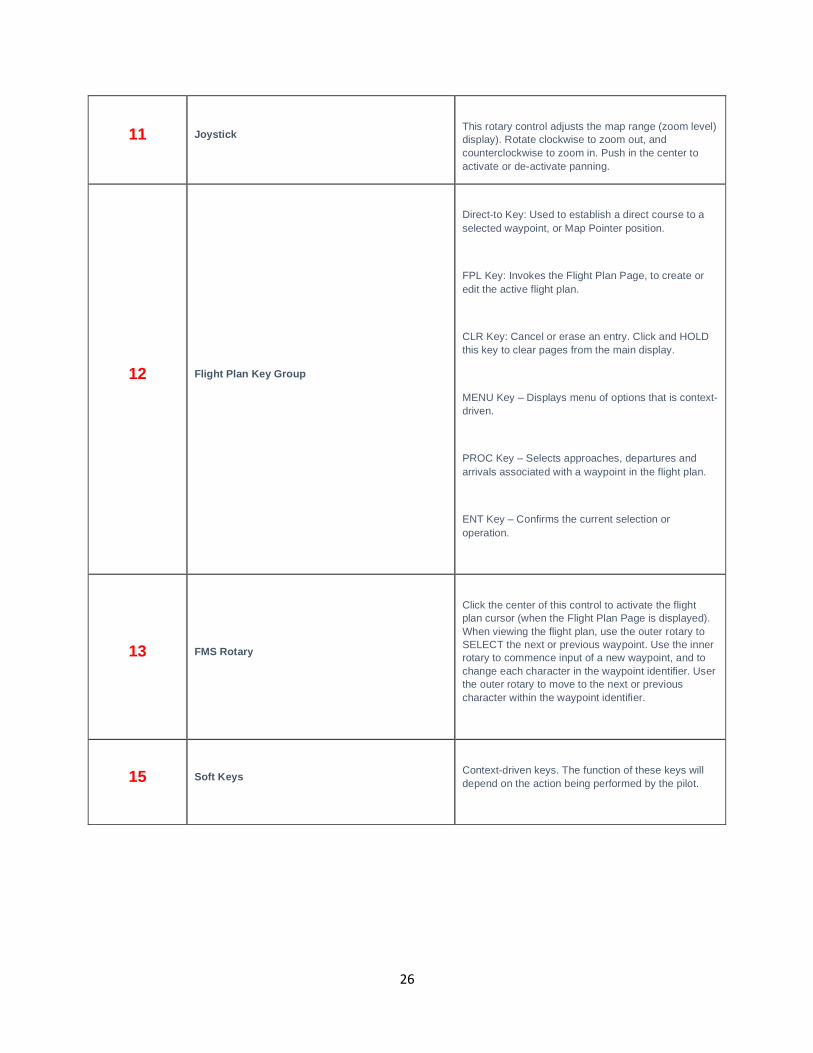
11 Joystick
This rotary control adjusts the map range (zoom level) display). Rotate clockwise to zoom out, and counterclockwise to zoom in. Push in the center to activate or de-activate panning.
12 Flight Plan Key Group
Direct-to Key: Used to establish a direct course to a selected waypoint, or Map Pointer position.
FPL Key: Invokes the Flight Plan Page, to create or edit the active flight plan.
CLR Key: Cancel or erase an entry. Click and HOLD this key to clear pages from the main display.
MENU Key – Displays menu of options that is context-driven.
PROC Key – Selects approaches, departures and arrivals associated with a waypoint in the flight plan.
ENT Key – Confirms the current selection or operation.
13 FMS Rotary
Click the center of this control to activate the flight plan cursor (when the Flight Plan Page is displayed). When viewing the flight plan, use the outer rotary to SELECT the next or previous waypoint. Use the inner rotary to commence input of a new waypoint, and to change each character in the waypoint identifier. User the outer rotary to move to the next or previous character within the waypoint identifier.
15 Soft Keys
Context-driven keys. The function of these keys will depend on the action being performed by the pilot.
27
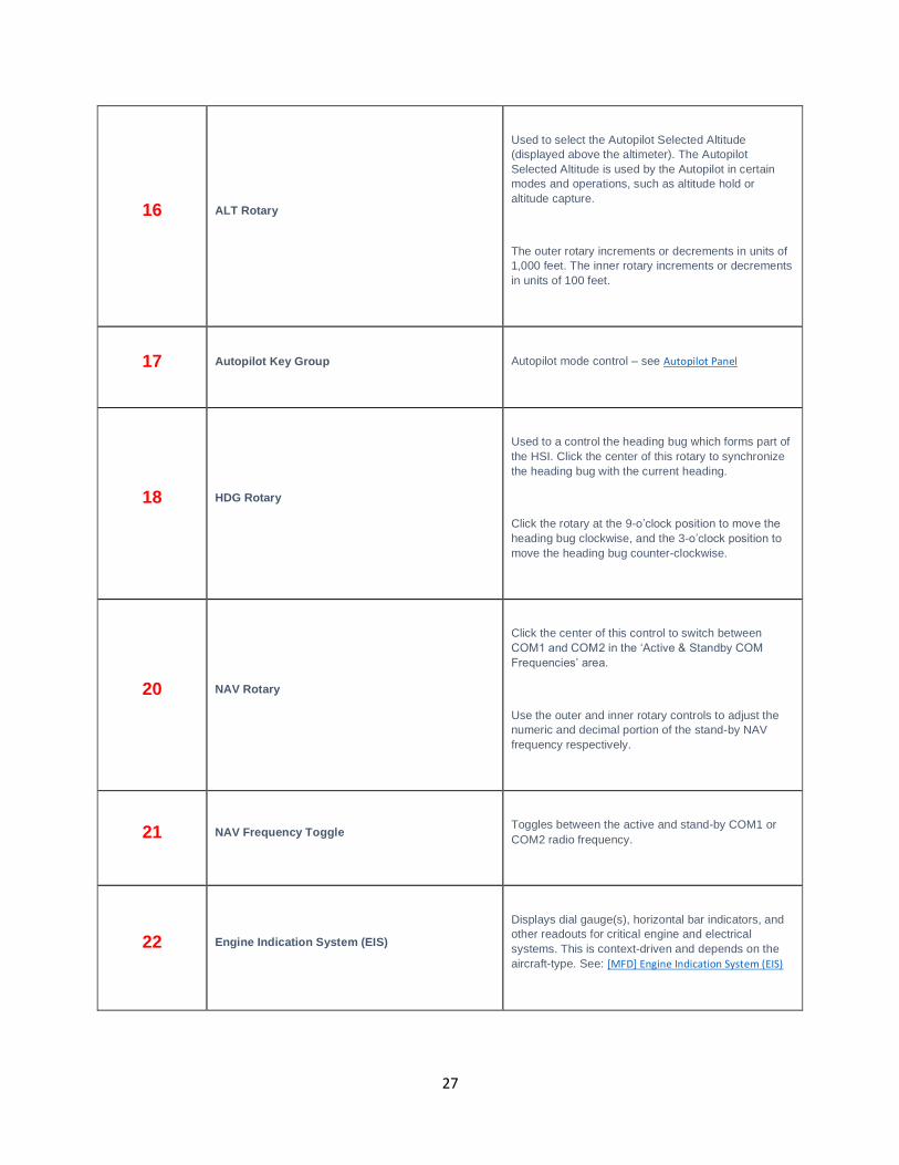
16 ALT Rotary
Used to select the Autopilot Selected Altitude (displayed above the altimeter). The Autopilot Selected Altitude is used by the Autopilot in certain modes and operations, such as altitude hold or altitude capture.
The outer rotary increments or decrements in units of 1,000 feet. The inner rotary increments or decrements in units of 100 feet.
17 Autopilot Key Group
Autopilot mode control – see Autopilot Panel
18 HDG Rotary
Used to a control the heading bug which forms part of the HSI. Click the center of this rotary to synchronize the heading bug with the current heading.
Click the rotary at the 9-o’clock position to move the
heading bug clockwise, and the 3-o’clock position to
move the heading bug counter-clockwise.
20 NAV Rotary
Click the center of this control to switch between COM1 and COM2 in the ‘Active & Standby COM
Frequencies’ area.
Use the outer and inner rotary controls to adjust the numeric and decimal portion of the stand-by NAV frequency respectively.
21 NAV Frequency Toggle
Toggles between the active and stand-by COM1 or COM2 radio frequency.
22 Engine Indication System (EIS)
Displays dial gauge(s), horizontal bar indicators, and other readouts for critical engine and electrical systems. This is context-driven and depends on the aircraft-type. See: [MFD] Engine Indication System (EIS)
28
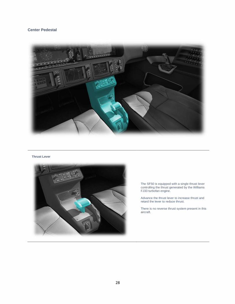
Center Pedestal
Thrust Lever
The SF50 is equipped with a single thrust lever controlling the thrust generated by the Williams FJ33 turbofan engine. Advance the thrust lever to increase thrust and retard the lever to reduce thrust. There is no reverse thrust system present in this aircraft.
29
Flap Lever
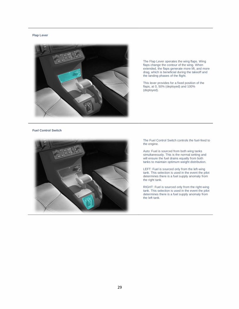
The Flap Lever operates the wing flaps. Wing flaps change the contour of the wing. When extended, the flaps generate more lift, and more drag, which is beneficial during the takeoff and the landing phases of the flight. This lever provides for a fixed position of the flaps, at 0, 50% (deployed) and 100% (deployed).
Fuel Control Switch
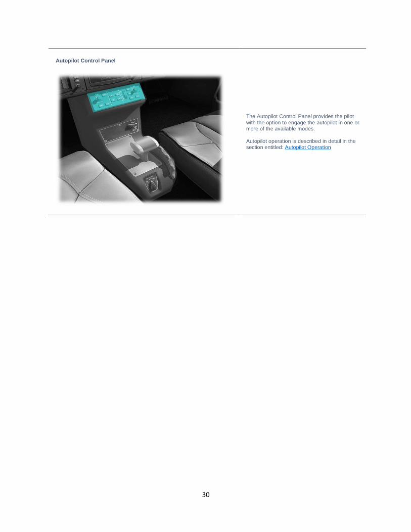
The Fuel Control Switch controls the fuel-feed to the engine. Auto: Fuel is sourced from both wing tanks simultaneously. This is the normal setting and will ensure the fuel drains equally from both tanks to maintain optimum weight distribution. LEFT: Fuel is sourced only from the left-wing tank. This selection is used in the event the pilot determines there is a fuel supply anomaly from the right tank. RIGHT: Fuel is sourced only from the right-wing tank. This selection is used in the event the pilot determines there is a fuel supply anomaly from the left tank.
30
Autopilot Control Panel
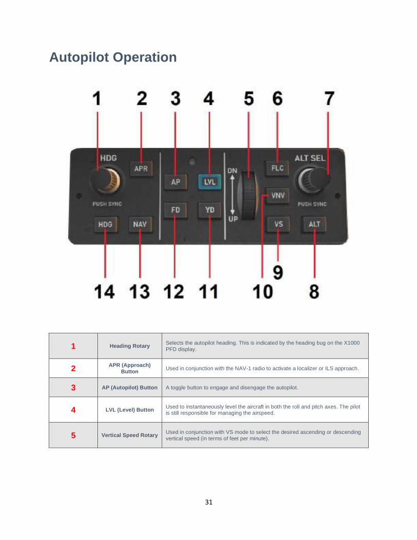
The Autopilot Control Panel provides the pilot with the option to engage the autopilot in one or more of the available modes. Autopilot operation is described in detail in the section entitled: Autopilot Operation
31
Autopilot Operation
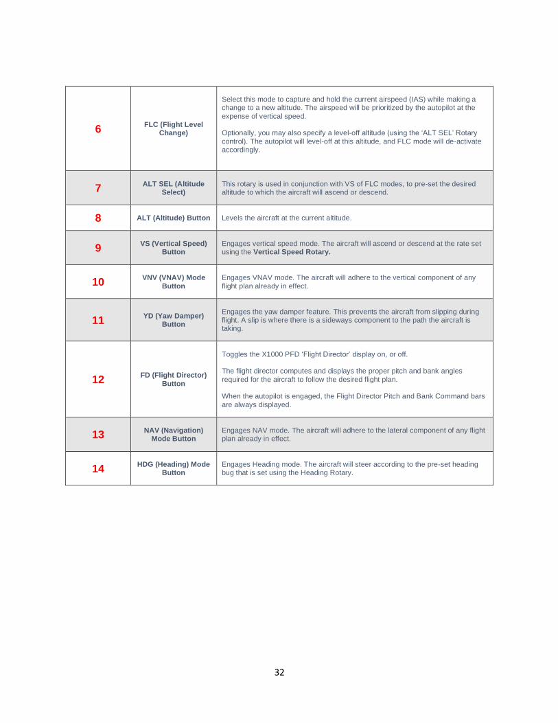
1 Heading Rotary
Selects the autopilot heading. This is indicated by the heading bug on the X1000 PFD display.
2 APR (Approach) Button
Used in conjunction with the NAV-1 radio to activate a localizer or ILS approach.
3 AP (Autopilot) Button A toggle button to engage and disengage the autopilot.
4 LVL (Level) Button
Used to instantaneously level the aircraft in both the roll and pitch axes. The pilot is still responsible for managing the airspeed.
5
Vertical Speed Rotary
Used in conjunction with VS mode to select the desired ascending or descending vertical speed (in terms of feet per minute).
32
6 FLC (Flight Level Change)
Select this mode to capture and hold the current airspeed (IAS) while making a change to a new altitude. The airspeed will be prioritized by the autopilot at the expense of vertical speed. Optionally, you may also specify a level-off altitude (using the ‘ALT SEL’ Rotary
control). The autopilot will level-off at this altitude, and FLC mode will de-activate accordingly.
7 ALT SEL (Altitude Select)
This rotary is used in conjunction with VS of FLC modes, to pre-set the desired altitude to which the aircraft will ascend or descend.
8 ALT (Altitude) Button Levels the aircraft at the current altitude.
9 VS (Vertical Speed) Button
Engages vertical speed mode. The aircraft will ascend or descend at the rate set using the Vertical Speed Rotary.
10 VNV (VNAV) Mode Button
Engages VNAV mode. The aircraft will adhere to the vertical component of any flight plan already in effect.
11 YD (Yaw Damper) Button
Engages the yaw damper feature. This prevents the aircraft from slipping during flight. A slip is where there is a sideways component to the path the aircraft is taking.
12 FD (Flight Director) Button
Toggles the X1000 PFD ‘Flight Director’ display on, or off. The flight director computes and displays the proper pitch and bank angles required for the aircraft to follow the desired flight plan. When the autopilot is engaged, the Flight Director Pitch and Bank Command bars are always displayed.
13 NAV (Navigation) Mode Button
Engages NAV mode. The aircraft will adhere to the lateral component of any flight plan already in effect.
14 HDG (Heading) Mode Button
Engages Heading mode. The aircraft will steer according to the pre-set heading bug that is set using the Heading Rotary.
33
ILS Approach
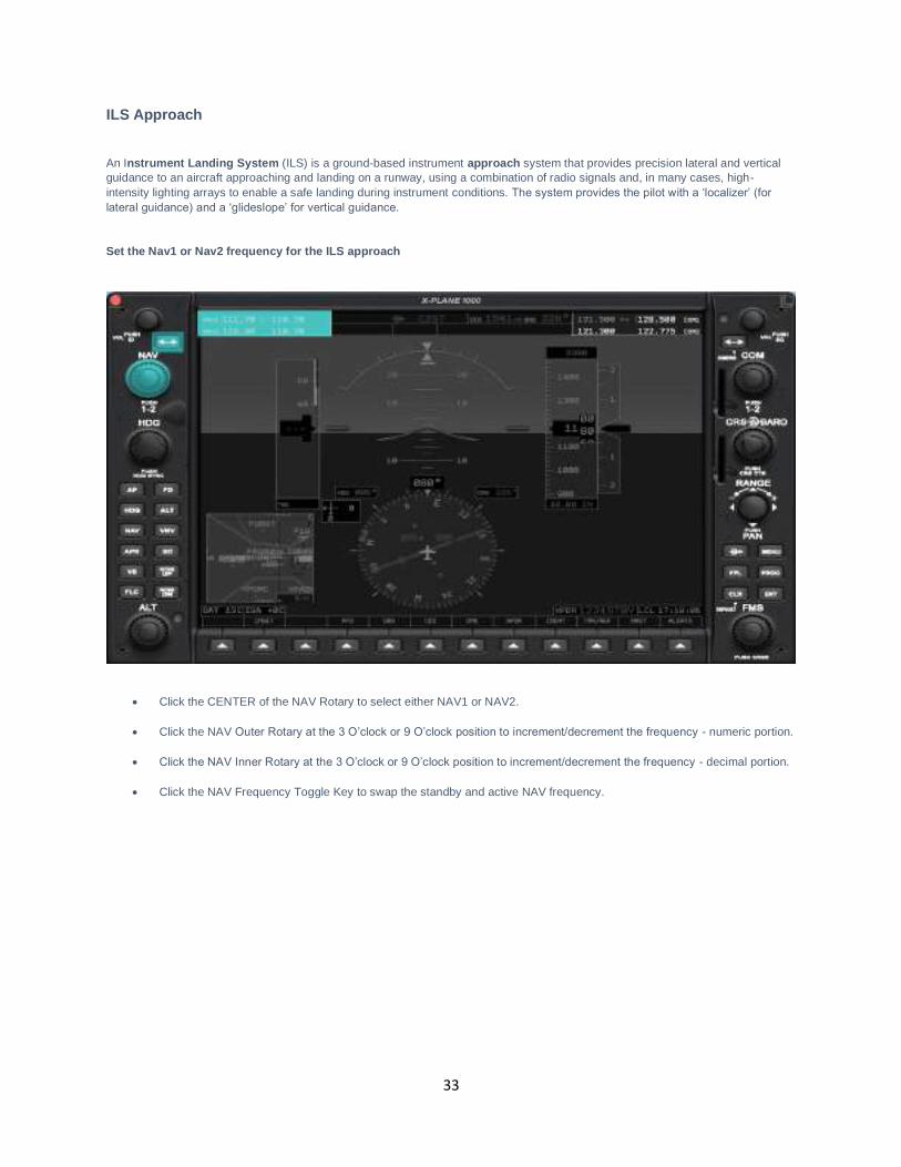
An Instrument Landing System (ILS) is a ground-based instrument approach system that provides precision lateral and vertical guidance to an aircraft approaching and landing on a runway, using a combination of radio signals and, in many cases, high-intensity lighting arrays to enable a safe landing during instrument conditions. The system provides the pilot with a ‘localizer’ (for
lateral guidance) and a ‘glideslope’ for vertical guidance.
Set the Nav1 or Nav2 frequency for the ILS approach
• Click the CENTER of the NAV Rotary to select either NAV1 or NAV2.
• Click the NAV Outer Rotary at the 3 O’clock or 9 O’clock position to increment/decrement the frequency - numeric portion.
• Click the NAV Inner Rotary at the 3 O’clock or 9 O’clock position to increment/decrement the frequency - decimal portion.
• Click the NAV Frequency Toggle Key to swap the standby and active NAV frequency.
34
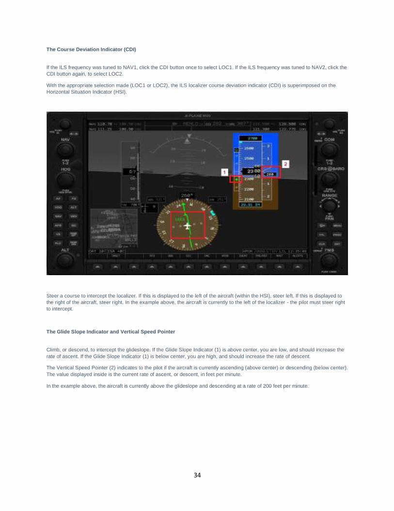
The Course Deviation Indicator (CDI)
If the ILS frequency was tuned to NAV1, click the CDI button once to select LOC1. If the ILS frequency was tuned to NAV2, click the CDI button again, to select LOC2.
With the appropriate selection made (LOC1 or LOC2), the ILS localizer course deviation indicator (CDI) is superimposed on the Horizontal Situation Indicator (HSI).
Steer a course to intercept the localizer. If this is displayed to the left of the aircraft (within the HSI), steer left. If this is displayed to the right of the aircraft, steer right. In the example above, the aircraft is currently to the left of the localizer - the pilot must steer right to intercept.
The Glide Slope Indicator and Vertical Speed Pointer
Climb, or descend, to intercept the glideslope. If the Glide Slope Indicator (1) is above center, you are low, and should increase the rate of ascent. If the Glide Slope Indicator (1) is below center, you are high, and should increase the rate of descent.
The Vertical Speed Pointer (2) indicates to the pilot if the aircraft is currently ascending (above center) or descending (below center). The value displayed inside is the current rate of ascent, or descent, in feet per minute.
In the example above, the aircraft is currently above the glideslope and descending at a rate of 200 feet per minute.
35
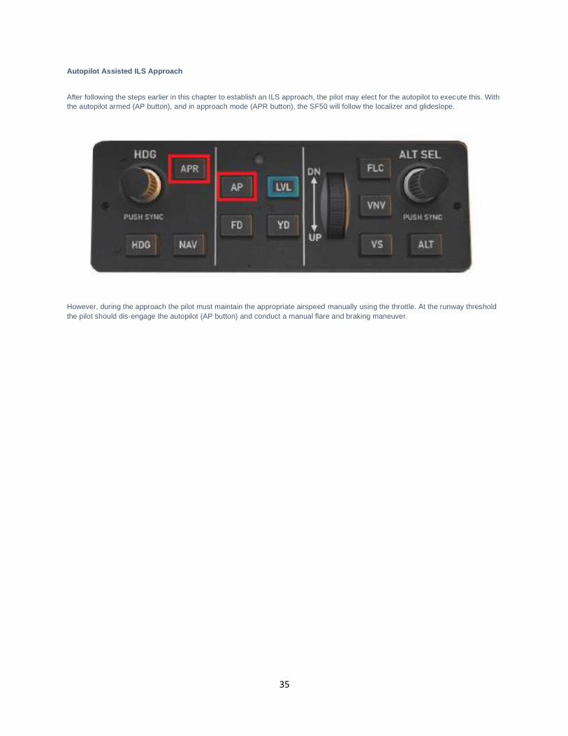
Autopilot Assisted ILS Approach
After following the steps earlier in this chapter to establish an ILS approach, the pilot may elect for the autopilot to execute this. With the autopilot armed (AP button), and in approach mode (APR button), the SF50 will follow the localizer and glideslope.
However, during the approach the pilot must maintain the appropriate airspeed manually using the throttle. At the runway threshold the pilot should dis-engage the autopilot (AP button) and conduct a manual flare and braking maneuver.

36
Flight Planning
Flight planning is the process of determining a route from origin to destination that considers fuel requirements, terrain avoidance, Air Traffic Control, aircraft performance, airspace restrictions and notices to airmen (NOTAMS).
General information about flight plans is available on Wikipedia at http://en.wikipedia.org/wiki/Flight_planning
Flight plans can be generated by onboard computers if the aircraft is suitably equipped. If not, simulation pilots may elect to use an online flight planner. A web search for the phrase “Flight Planner” will yield a great many options, many of which are free services.
A good online flight planner will utilize the origin and destination airports, together with the aircraft type and equipment, the weather conditions, the chosen cruise altitude, known restrictions along the route, current NOTAMS, and other factors to generate a suitable flight plan. The waypoints incorporated into the flight plan can be subsequently input into the aircraft’s Flight Management Computer (FMS), or Global Positioning System (GPS). Some online flight planners provide the option to save the plan as an X-Plane compatible file, with an ‘fms’ extension. A saved flight plan can be loaded into the GPS or Flight Management Computer unit featured in the SF50.
It is recommended the pilot generate a flight plan for the chosen route before using the FMS or GPS units.
Instructions for operating the Laminar Research FMS and GPS units can be found in separate (dedicated) manuals.

37
Fuel Calculation
Note: All calculations here are based on the X-Plane SF50, and NOT the real SF50. Differences may exist.
Load Sheet Tables
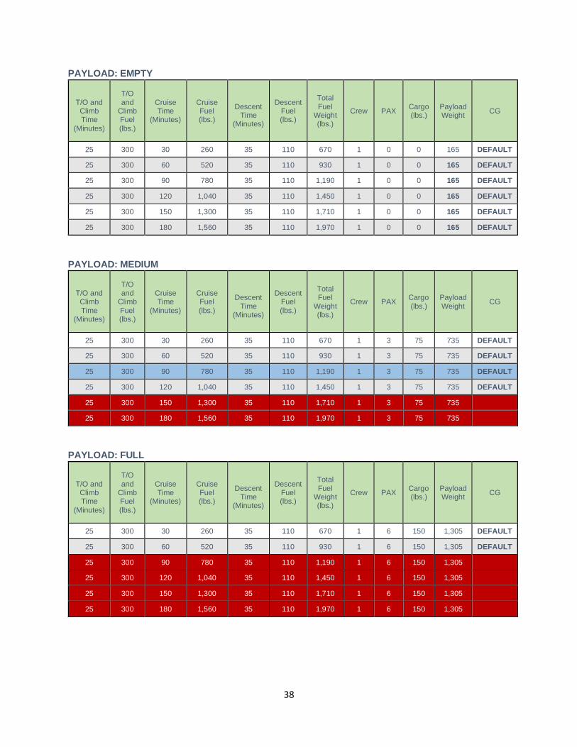
The tables in the next pages illustrate a series of hypothetical load-sheet scenarios. For these purposes, passengers are deemed to have an average weight of 165 lbs. and cruise will be 300 KTAS @ 25,000 feet.
These calculations do not include taxi operations. Add 50 lbs. of fuel for normal taxi operations and 100 lbs. of fuel for extended taxi operations.
38
PAYLOAD: EMPTY
T/O and Climb Time
(Minutes)
T/O and
Climb Fuel (lbs.)
Cruise Time
(Minutes)
Cruise Fuel (lbs.)
Descent
Time (Minutes)
Descent Fuel (lbs.)
Total Fuel
Weight (lbs.)
Crew PAX Cargo (lbs.)
Payload Weight CG
25 300 30 260 35 110 670 1 0 0 165 DEFAULT
25 300 60 520 35 110 930 1 0 0 165 DEFAULT
25 300 90 780 35 110 1,190 1 0 0 165 DEFAULT
25 300 120 1,040 35 110 1,450 1 0 0 165 DEFAULT
25 300 150 1,300 35 110 1,710 1 0 0 165 DEFAULT
25 300 180 1,560 35 110 1,970 1 0 0 165 DEFAULT
PAYLOAD: MEDIUM
T/O and Climb Time
(Minutes)
T/O and
Climb Fuel (lbs.)
Cruise Time
(Minutes)
Cruise Fuel (lbs.)
Descent
Time (Minutes)
Descent Fuel (lbs.)
Total Fuel
Weight (lbs.)
Crew PAX Cargo (lbs.)
Payload Weight
CG
25 300 30 260 35 110 670 1 3 75 735 DEFAULT
25 300 60 520 35 110 930 1 3 75 735 DEFAULT
25 300 90 780 35 110 1,190 1 3 75 735 DEFAULT
25 300 120 1,040 35 110 1,450 1 3 75 735 DEFAULT
25 300 150 1,300 35 110 1,710 1 3 75 735
25 300 180 1,560 35 110 1,970 1 3 75 735
PAYLOAD: FULL
T/O and Climb Time
(Minutes)
T/O and
Climb Fuel (lbs.)
Cruise Time
(Minutes)
Cruise Fuel (lbs.)
Descent
Time (Minutes)
Descent Fuel (lbs.)
Total Fuel
Weight (lbs.)
Crew PAX Cargo (lbs.)
Payload Weight CG
25 300 30 260 35 110 670 1 6 150 1,305 DEFAULT
25 300 60 520 35 110 930 1 6 150 1,305 DEFAULT
25 300 90 780 35 110 1,190 1 6 150 1,305
25 300 120 1,040 35 110 1,450 1 6 150 1,305
25 300 150 1,300 35 110 1,710 1 6 150 1,305
25 300 180 1,560 35 110 1,970 1 6 150 1,305
39
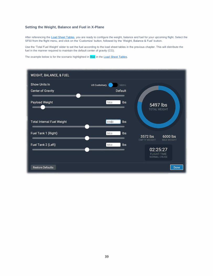
Setting the Weight, Balance and Fuel in X-Plane
After referencing the Load Sheet Tables, you are ready to configure the weight, balance and fuel for your upcoming flight. Select the SF50 from the flight menu, and click on the ‘Customize’ button, followed by the ‘Weight, Balance & Fuel’ button.
Use the ‘Total Fuel Weight’ slider to set the fuel according to the load sheet tables in the previous chapter. This will distribute the fuel in the manner required to maintain the default center of gravity (CG).
The example below is for the scenario highlighted in blue in the Load Sheet Tables.
40
Checklists
The following check lists are designed with the convenience of the simulation pilot in mind and customized to the X-Plane SF50 aircraft. These differ from those of the real aircraft.
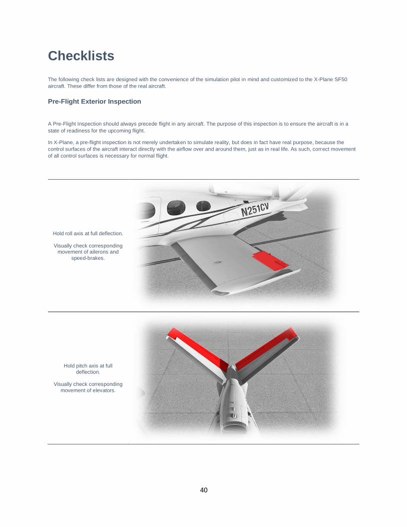
Pre-Flight Exterior Inspection
A Pre-Flight Inspection should always precede flight in any aircraft. The purpose of this inspection is to ensure the aircraft is in a state of readiness for the upcoming flight.
In X-Plane, a pre-flight inspection is not merely undertaken to simulate reality, but does in fact have real purpose, because the control surfaces of the aircraft interact directly with the airflow over and around them, just as in real life. As such, correct movement of all control surfaces is necessary for normal flight.
Hold roll axis at full deflection.
Visually check corresponding movement of ailerons and
speed-brakes.
Hold pitch axis at full
deflection.
Visually check corresponding movement of elevators.
41
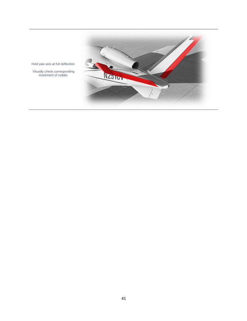
Hold yaw axis at full deflection.
Visually check corresponding movement of rudder.
42
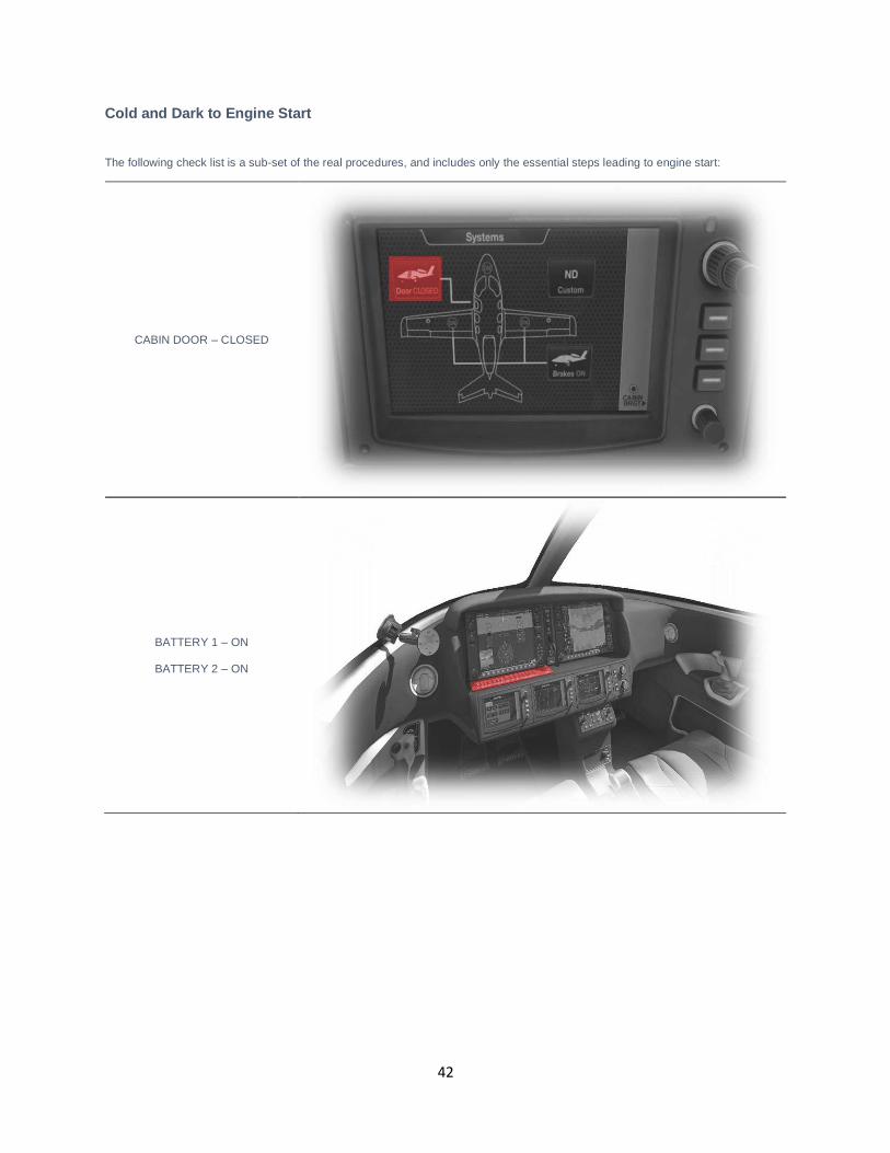
Cold and Dark to Engine Start
The following check list is a sub-set of the real procedures, and includes only the essential steps leading to engine start:
CABIN DOOR – CLOSED
BATTERY 1 – ON
BATTERY 2 – ON
43
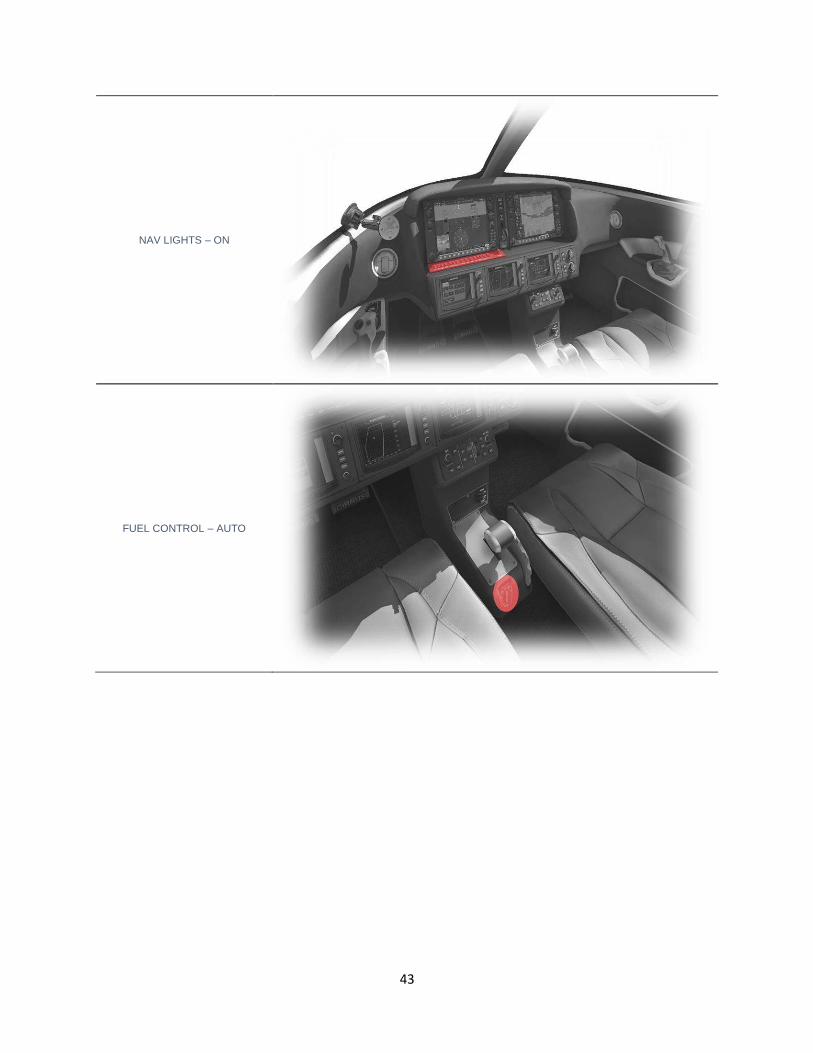
NAV LIGHTS – ON
FUEL CONTROL – AUTO
44
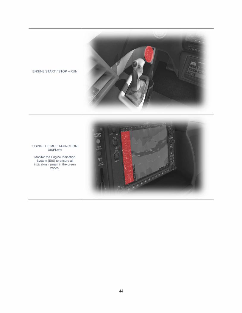
ENGINE START / STOP – RUN
USING THE MULTI-FUNCTION DISPLAY:
Monitor the Engine Indication
System (EIS) to ensure all indicators remain in the green
zones.
45
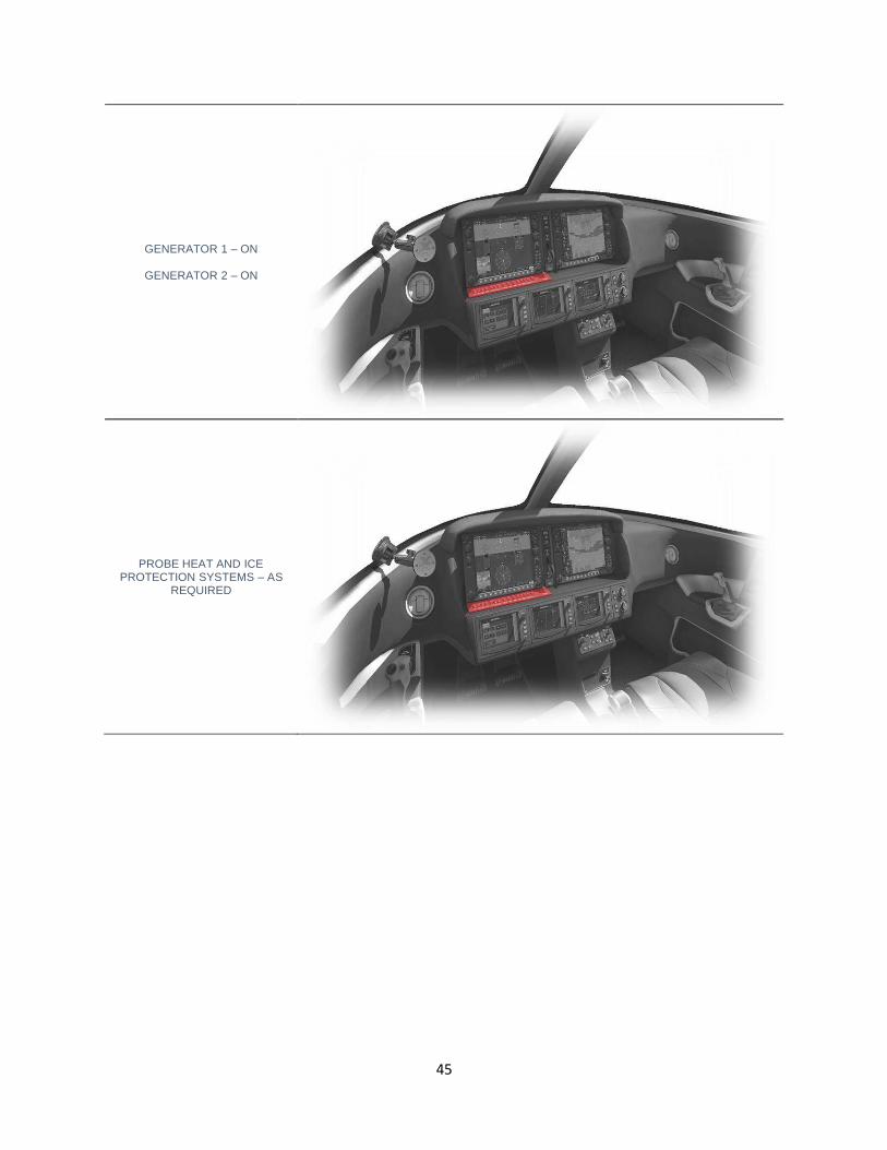
GENERATOR 1 – ON
GENERATOR 2 – ON
PROBE HEAT AND ICE PROTECTION SYSTEMS – AS
REQUIRED
46
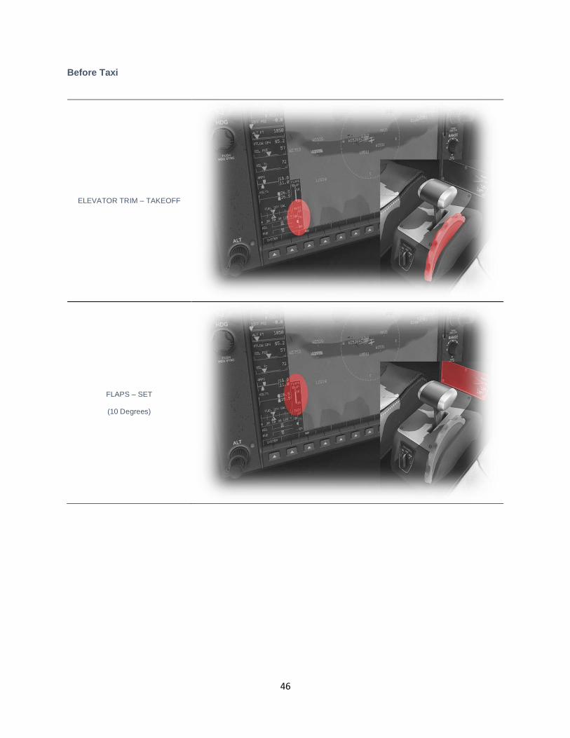
Before Taxi
ELEVATOR TRIM – TAKEOFF
FLAPS – SET
(10 Degrees)
47
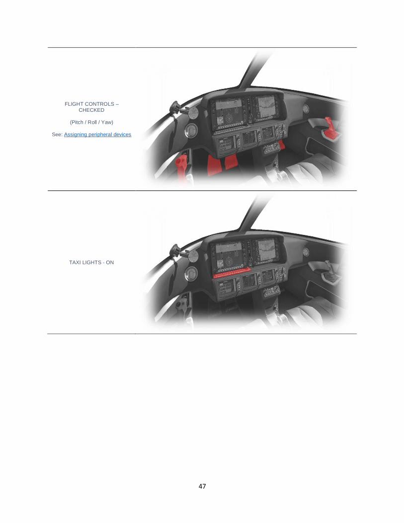
FLIGHT CONTROLS – CHECKED
(Pitch / Roll / Yaw)
See: Assigning peripheral devices
TAXI LIGHTS - ON
48
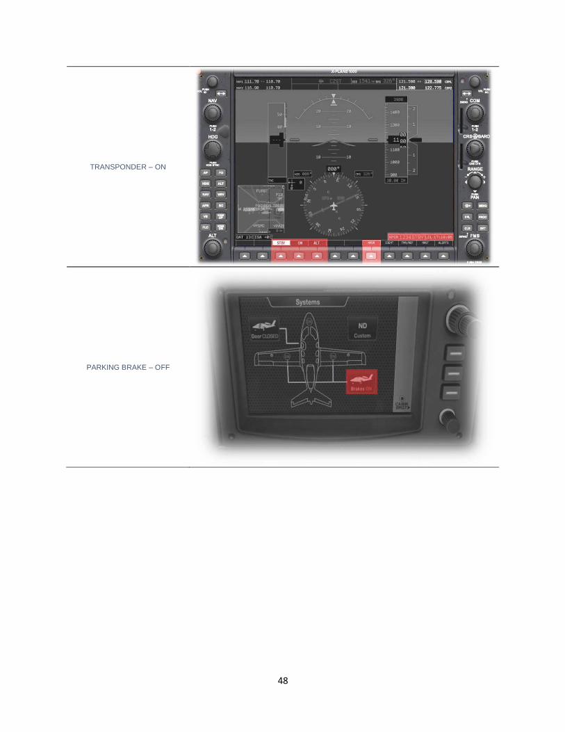
TRANSPONDER – ON
PARKING BRAKE – OFF
49
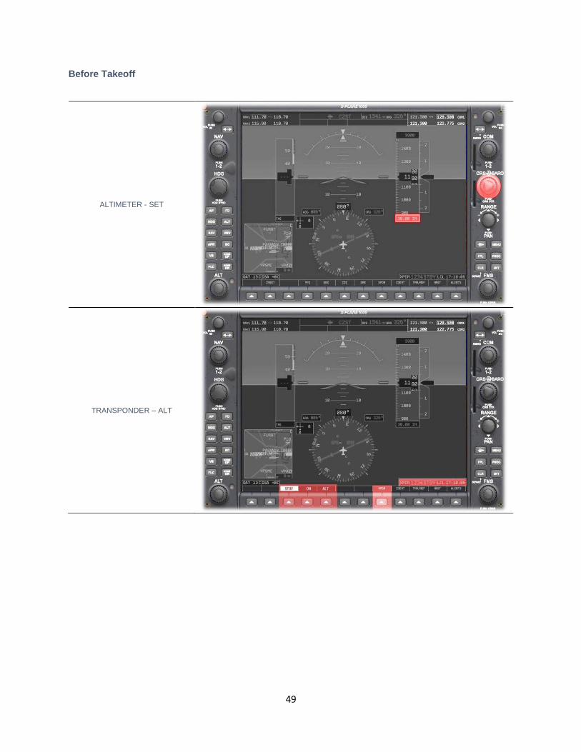
Before Takeoff
ALTIMETER - SET
TRANSPONDER – ALT
50
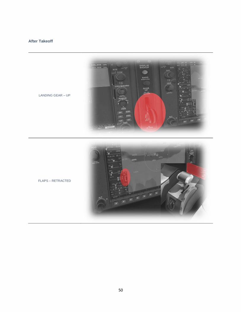
After Takeoff
LANDING GEAR – UP
FLAPS – RETRACTED
51
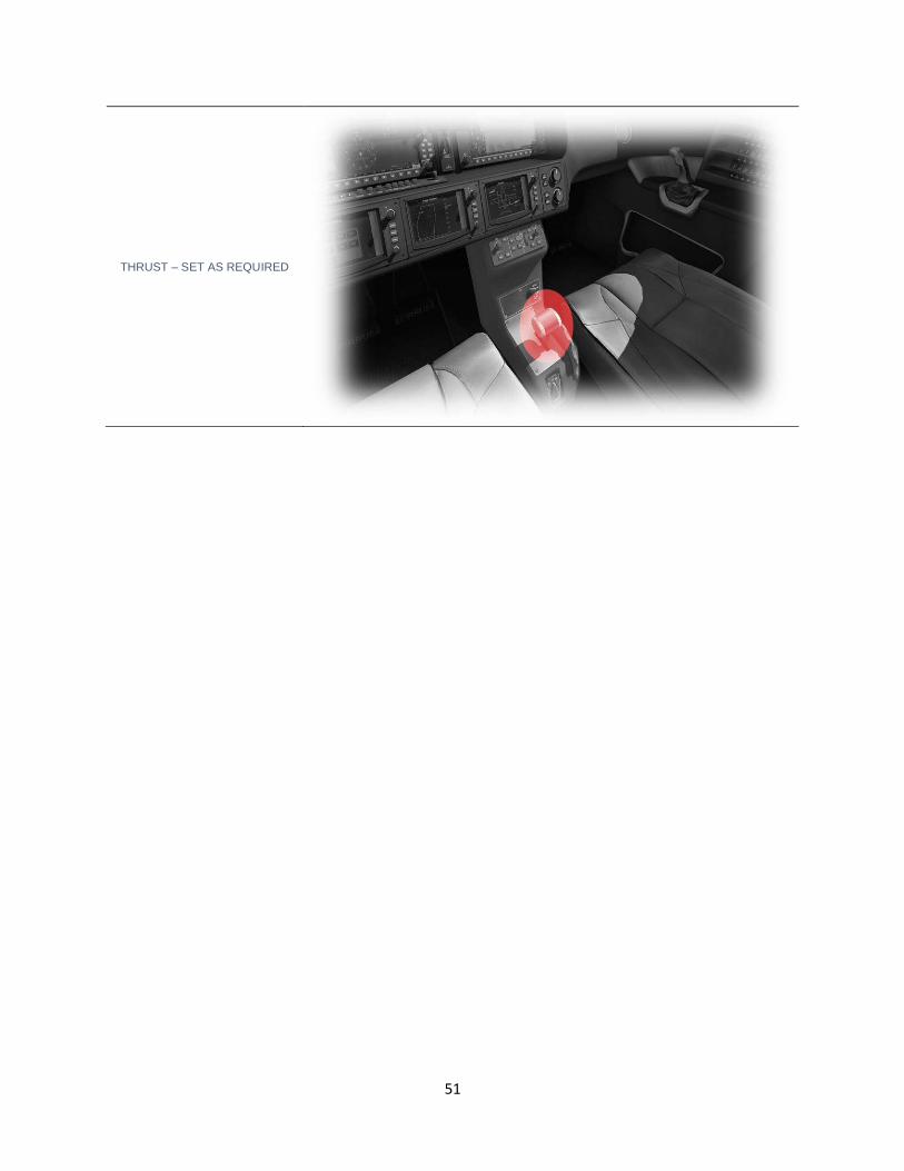
THRUST – SET AS REQUIRED
52
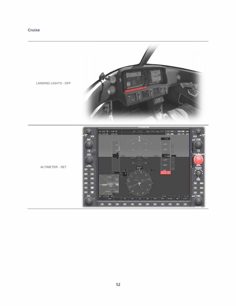
Cruise
LANDING LIGHTS - OFF
ALTIMETER - SET
53
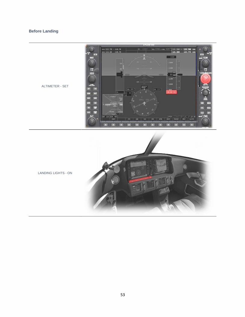
Before Landing
ALTIMETER - SET
LANDING LIGHTS - ON
54
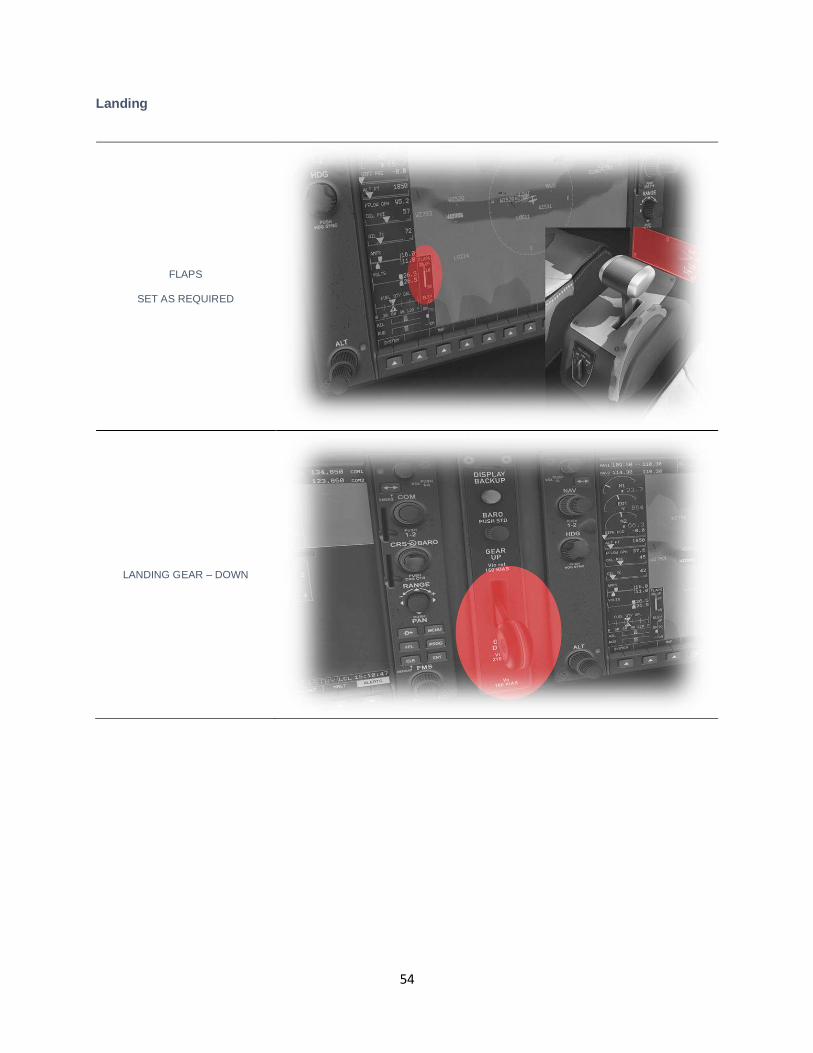
Landing
FLAPS
SET AS REQUIRED
LANDING GEAR – DOWN
55
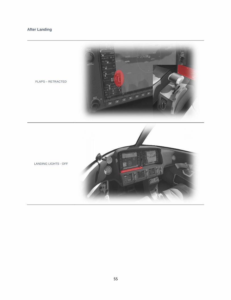
After Landing
FLAPS – RETRACTED
LANDING LIGHTS - OFF
56
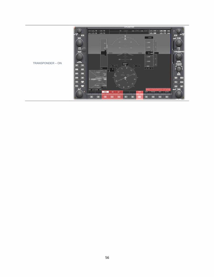
TRANSPONDER – ON
57
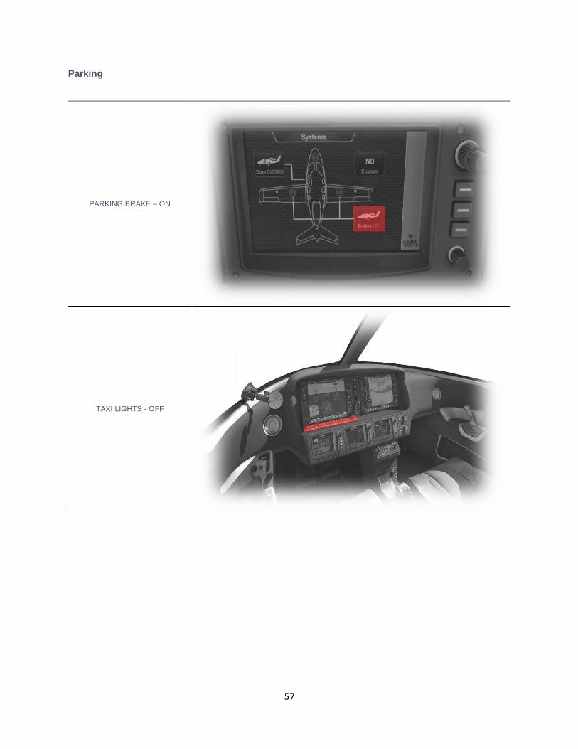
Parking
PARKING BRAKE – ON
TAXI LIGHTS - OFF
58
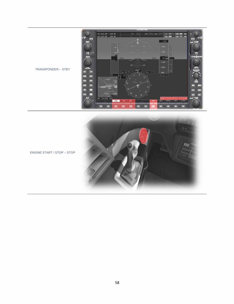
TRANSPONDER – STBY
ENGINE START / STOP – STOP
59
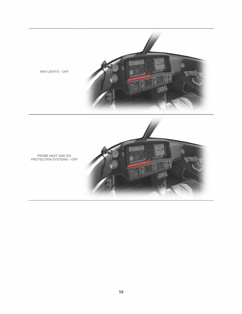
NAV LIGHTS – OFF
PROBE HEAT AND ICE PROTECTION SYSTEMS – OFF

60
GENERATOR 1 – OFF
GENERATOR 2 – OFF
BATTERY 1 – OFF
BATTERY 2 – OFF