ws16_normal modes w_ rbe2 _ conm2
DESCRIPTION
Finite Element Analysis - Normal ModesTRANSCRIPT
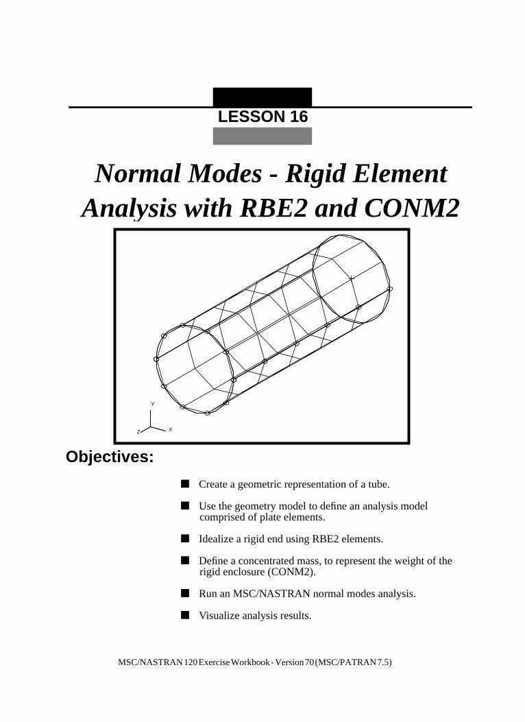
Normal Modes - Rigid ElementAnalysis with RBE2 and CONM2
Y
Z
Y
Z
Z
Z
X
Z
Y
LESSON 16
he
Objectives:
■ Create a geometric representation of a tube.
■ Use the geometry model to define an analysis modelcomprised of plate elements.
■ Idealize a rigid end using RBE2 elements.
■ Define a concentrated mass, to represent the weight of trigid enclosure (CONM2).
■ Run an MSC/NASTRAN normal modes analysis.
■ Visualize analysis results.
MSC/NASTRAN120ExerciseWorkbook-Version70(MSC/PATRAN7.5)

16-2 MSC/NASTRAN 120 Exercise Workbook - Version 70 (MSC/PATRAN 7.5)
LESSON 16 Rigid Element Analysis with RBE2
.
e
lto
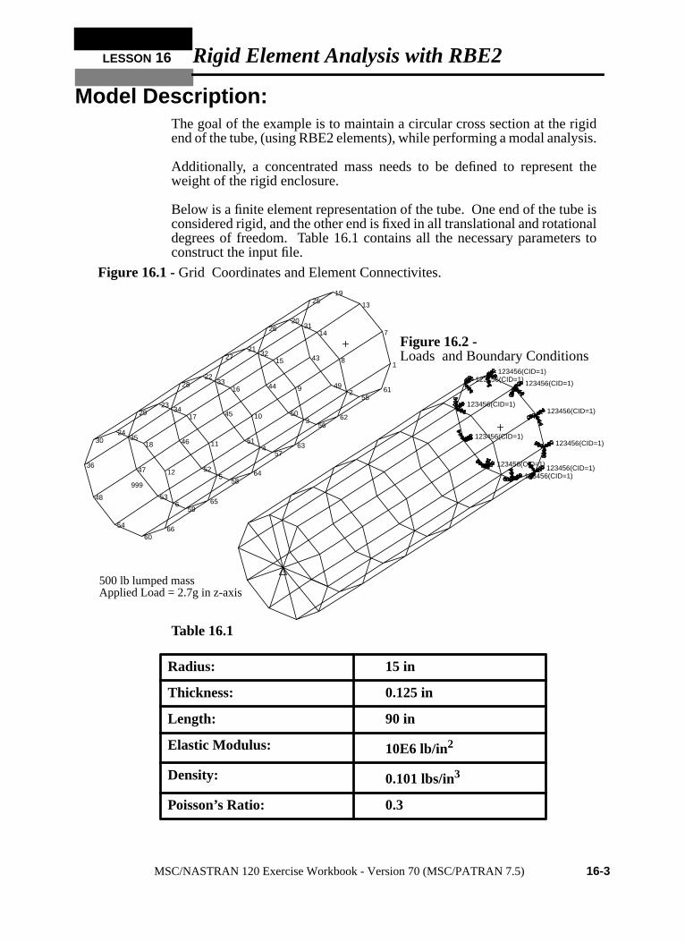
Model Description:The goal of the example is to maintain a circular cross section at the rigidend of the tube, (using RBE2 elements), while performing a modal analysis
Additionally, a concentrated mass needs to be defined to represent thweight of the rigid enclosure.
Below is a finite element representation of the tube. One end of the tube isconsidered rigid, and the other end is fixed in all translational and rotationadegrees of freedom. Table 16.1 contains all the necessary parametersconstruct the input file.
Table 16.1
Radius: 15 in
Thickness: 0.125 in
Length: 90 in
Elastic Modulus: 10E6 lb/in2
Density: 0.101 lbs/in3
Poisson’s Ratio: 0.3
Figure 16.2 -
Figure 16.1 -Grid Coordinates and Element Connectivites.
1
2
3
4
5
7
8
9
10
11
13
14
15
16
17
19
20
21
22
23
25
26
27
28
29
31
32
33
34
35
43
44
45
46
47
49
50
51
52
53
55
56
57
58
59
61
62
63
64
65
999
6
12
18
2430
36
48
54
6066
123456(CID=1)
123456(CID=1)
123456(CID=1)
123456(CID=1) 123456(CID=1)
123456(CID=1)
123456(CID=1)
123456(CID=1)
123456(CID=1) 123456(CID=1)
500 lb lumped massApplied Load = 2.7g in z-axis
Loads and Boundary Conditions
MSC/NASTRAN 120 Exercise Workbook - Version 70 (MSC/PATRAN 7.5) 16-3

ure4)
int
re,
Suggested Exercise Steps:
■ Generate a finite element representation of the cylinder struct( i.e., The nodes (GRID) and element connectivities (CQUADshould be defined manually).
■ Define material (MAT1) and element (PSHELL) properties.
■ Create grid point 999 at the center of the rigid end. This pois to serve as the load application point, as well as theconnection point for the rigid element.
■ Idealize the rigid end with rigid elements (RBE2).
■ Apply the fixed boundary constraints (SPC1).
■ Apply a concentrated mass at the center of the top enclosuGrid 999 (CONM2).
■ Prepare the model for normal modes analysis (SOL 103).
■ Generate an input file and submit it to the MSC/NASTRANsolver for normal modes analysis.
■ Review the results.
16-4 MSC/NASTRAN 120 Exercise Workbook - Version 70 (MSC/PATRAN 7.5)
LESSON 16 Rigid Element Analysis with RBE2
ID SEMINAR, LESSON 16______________________________________________________________________________________________________________________________________________________________________________________________________________________________________________________________________________________________________________________________________________________________________________________________________________________________________________________________________________CEND________________________________________________________________________________________________________________________________________________________________________________________________________________________________________________________________________________________________________________________________________________________________________________________________________________________________________________________________________________________________________________________________________________________________________________________________________________________________________________________________________________________________________________________________________________________________________________________________________________________________________________________________________________________________________________________________________________________________________________________________________________________________________________________________________________________________________________________________________________________________________________________________________________________________________________________________________________________________________________________________________________________________________________________________________________________________________________________________________________________________________________________________________________________________________________________________________________________________________________________________________________________BEGIN BULK
MSC/NASTRAN 120 Exercise Workbook - Version 70 (MSC/PATRAN 7.5) 16-5

1 2 3 4 5 6 7 8 9 10
16-6 MSC/NASTRAN 120 Exercise Workbook - Version 70 (MSC/PATRAN 7.5)

LESSON 16 Rigid Element Analysis with RBE2
1 2 3 4 5 6 7 8 9 10
ENDDATA
MSC/NASTRAN 120 Exercise Workbook - Version 70 (MSC/PATRAN 7.5) 16-7
r
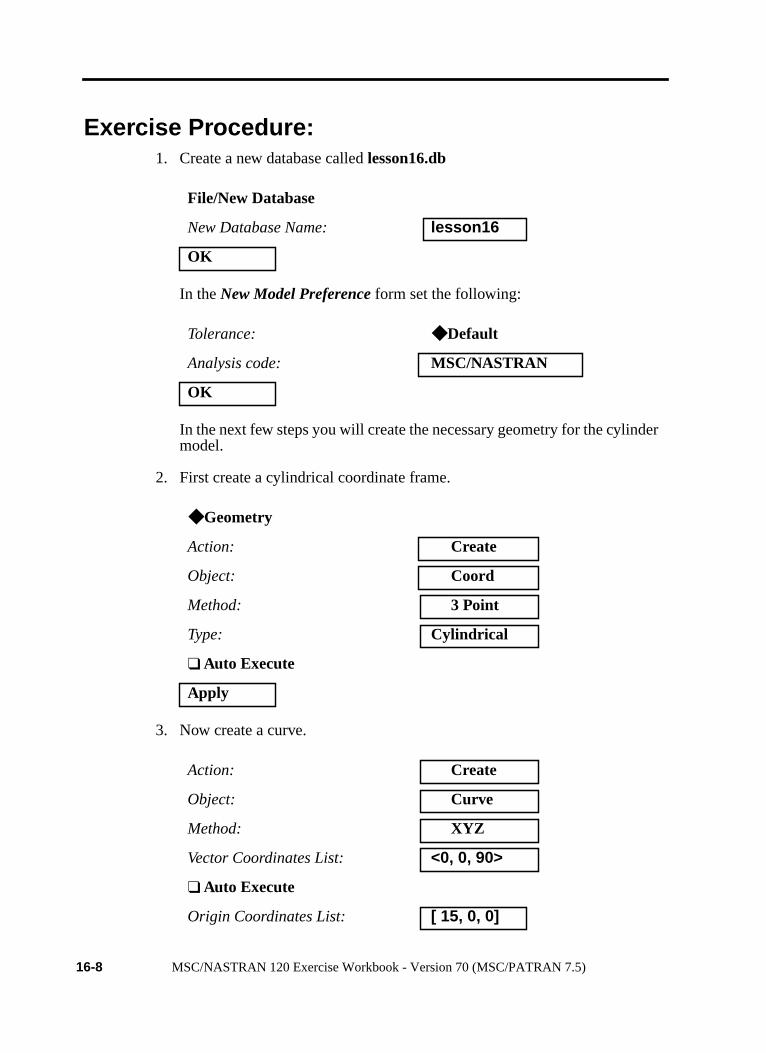
Exercise Procedure:1. Create a new database calledlesson16.db
In theNew Model Preference form set the following:
In the next few steps you will create the necessary geometry for the cylindemodel.
2. First create a cylindrical coordinate frame.
3. Now create a curve.
File/New Database
New Database Name: lesson16
OK
Tolerance: ◆ Default
Analysis code: MSC/NASTRAN
OK
◆ Geometry
Action: Create
Object: Coord
Method: 3 Point
Type: Cylindrical
❑ Auto Execute
Apply
Action: Create
Object: Curve
Method: XYZ
Vector Coordinates List: <0, 0, 90>
❑ Auto Execute
Origin Coordinates List: [ 15, 0, 0]
16-8 MSC/NASTRAN 120 Exercise Workbook - Version 70 (MSC/PATRAN 7.5)
LESSON 16 Rigid Element Analysis with RBE2
e
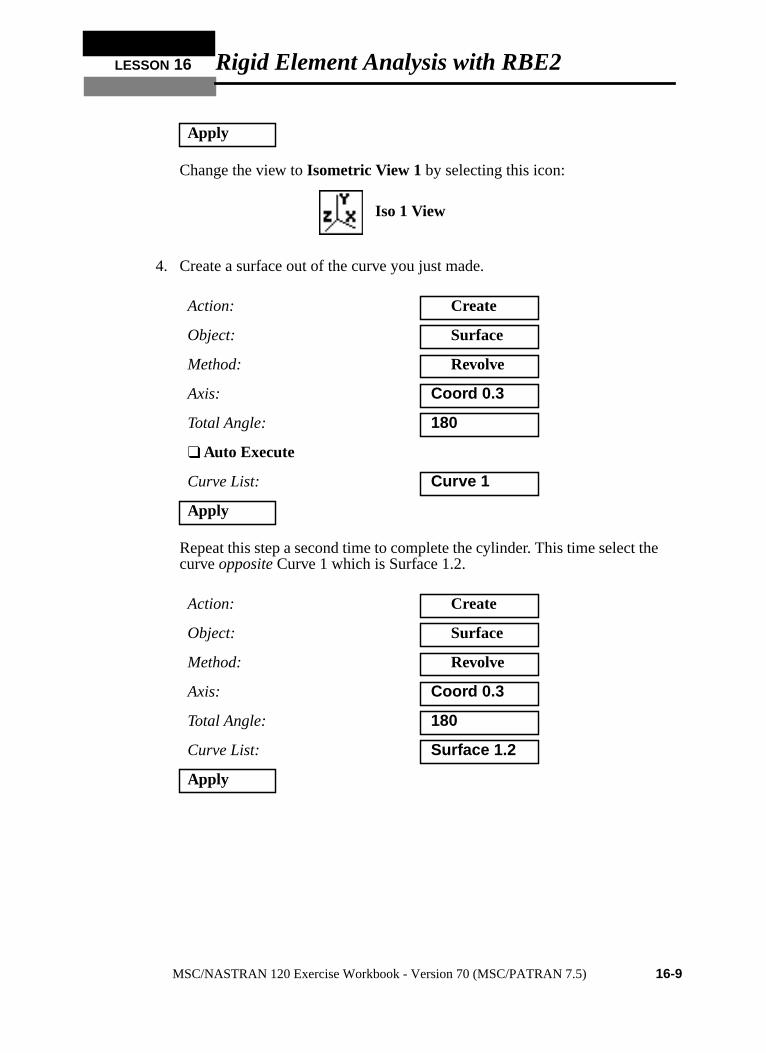
Change the view toIsometric View 1 by selecting this icon:
4. Create a surface out of the curve you just made.
Repeat this step a second time to complete the cylinder. This time select thcurveopposite Curve 1 which is Surface 1.2.
Apply
Action: Create
Object: Surface
Method: Revolve
Axis: Coord 0.3
Total Angle: 180
❑ Auto Execute
Curve List: Curve 1
Apply
Action: Create
Object: Surface
Method: Revolve
Axis: Coord 0.3
Total Angle: 180
Curve List: Surface 1.2
Apply
Iso 1 View
MSC/NASTRAN 120 Exercise Workbook - Version 70 (MSC/PATRAN 7.5) 16-9

Figure 16.3- Your model should appear as below
5. Create the finite element model and mesh the surface.
First you will create 5 mesh seeds along the top and bottom edges,Surface 1.3 2.3, and 5 along the Curve 1.
◆ Finite Elements
Action: Create
Object: Mesh Seed
Type: Uniform
◆ Number of Elements
Number: 5
❑ Auto Execute
Curve List:(See Figure 16.3.)
Curve 1, Surface 1.3 2.3
Apply
Surface 1.3
Surface 2.3
Curve 1
Surface 1.2
X
Y
Z
16-10 MSC/NASTRAN 120 Exercise Workbook - Version 70 (MSC/PATRAN 7.5)
LESSON 16 Rigid Element Analysis with RBE2
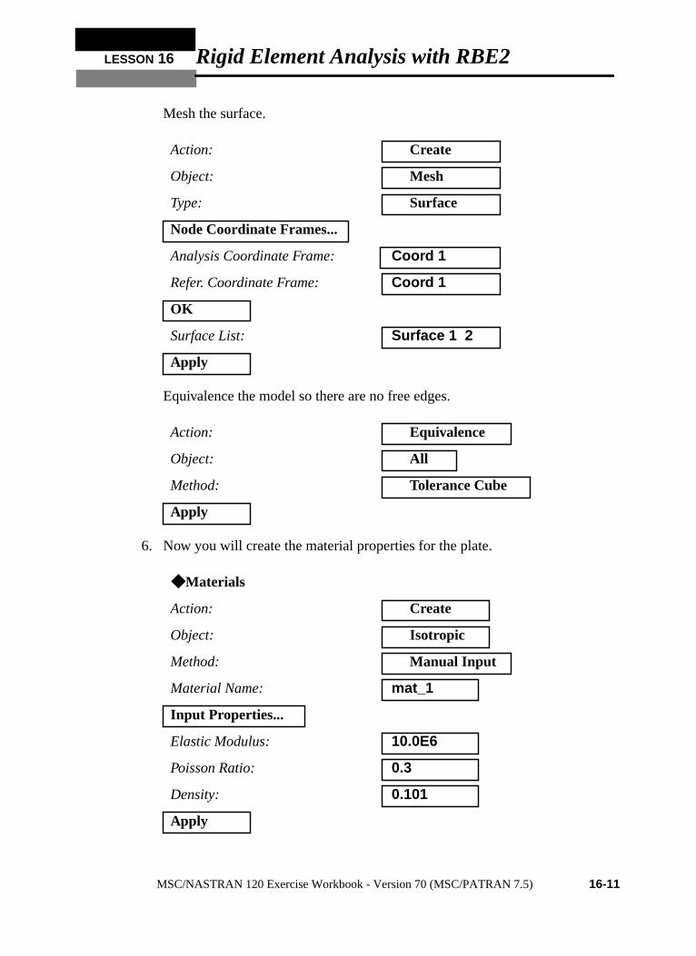
Mesh the surface.
Equivalence the model so there are no free edges.
6. Now you will create the material properties for the plate.
Action: Create
Object: Mesh
Type: Surface
Node Coordinate Frames...
Analysis Coordinate Frame: Coord 1
Refer. Coordinate Frame: Coord 1
OK
Surface List: Surface 1 2
Apply
Action: Equivalence
Object: All
Method: Tolerance Cube
Apply
◆ Materials
Action: Create
Object: Isotropic
Method: Manual Input
Material Name: mat_1
Input Properties...
Elastic Modulus: 10.0E6
Poisson Ratio: 0.3
Density: 0.101
Apply
MSC/NASTRAN 120 Exercise Workbook - Version 70 (MSC/PATRAN 7.5) 16-11
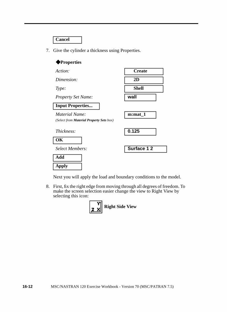
7. Give the cylinder a thickness using Properties.
Next you will apply the load and boundary conditions to the model.
8. First, fix the right edge from moving through all degrees of freedom. Tomake the screen selection easier change the view to Right View byselecting this icon:
Cancel
◆ Properties
Action: Create
Dimension: 2D
Type: Shell
Property Set Name: wall
Input Properties...
Material Name:(Select fromMaterial Property Setsbox)
m:mat_1
Thickness: 0.125
OK
Select Members: Surface 1 2
Add
Apply
Right Side View
16-12 MSC/NASTRAN 120 Exercise Workbook - Version 70 (MSC/PATRAN 7.5)
LESSON 16 Rigid Element Analysis with RBE2
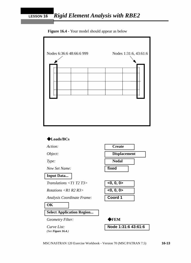
Figure 16.4- Your model should appear as below
◆ Loads/BCs
Action: Create
Object: Displacement
Type: Nodal
New Set Name: fixed
Input Data...
Translations <T1 T2 T3> <0, 0, 0>
Rotations <R1 R2 R3> <0, 0, 0>
Analysis Coordinate Frame: Coord 1
OK
Select Application Region...
Geometry Filter: ◆ FEM
Curve List:(SeeFigure 16.4.)
Node 1:31:6 43:61:6
Nodes 1:31:6, 43:61:6Nodes 6:36:6 48:66:6 999
MSC/NASTRAN 120 Exercise Workbook - Version 70 (MSC/PATRAN 7.5) 16-13
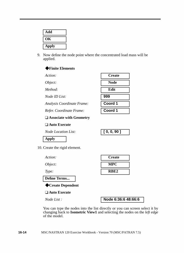
9. Now define the node point where the concentrated load mass will beapplied.
10. Create the rigid element.
You can type the nodes into the list directly or you can screen select it bychanging back toIsometric View1 and selecting the nodes on theleft edgeof the model.
Add
OK
Apply
◆ Finite Elements
Action: Create
Object: Node
Method: Edit
Node ID List: 999
Analysis Coordinate Frame: Coord 1
Refer. Coordinate Frame: Coord 1
❑ Associate with Geometry
❑ Auto Execute
Node Location List: [ 0, 0, 90 ]
Apply
Action: Create
Object: MPC
Type: RBE2
Define Terms...
◆ Create Dependent
❑ Auto Execute
Node List : Node 6:36:6 48:66:6
16-14 MSC/NASTRAN 120 Exercise Workbook - Version 70 (MSC/PATRAN 7.5)
LESSON 16 Rigid Element Analysis with RBE2
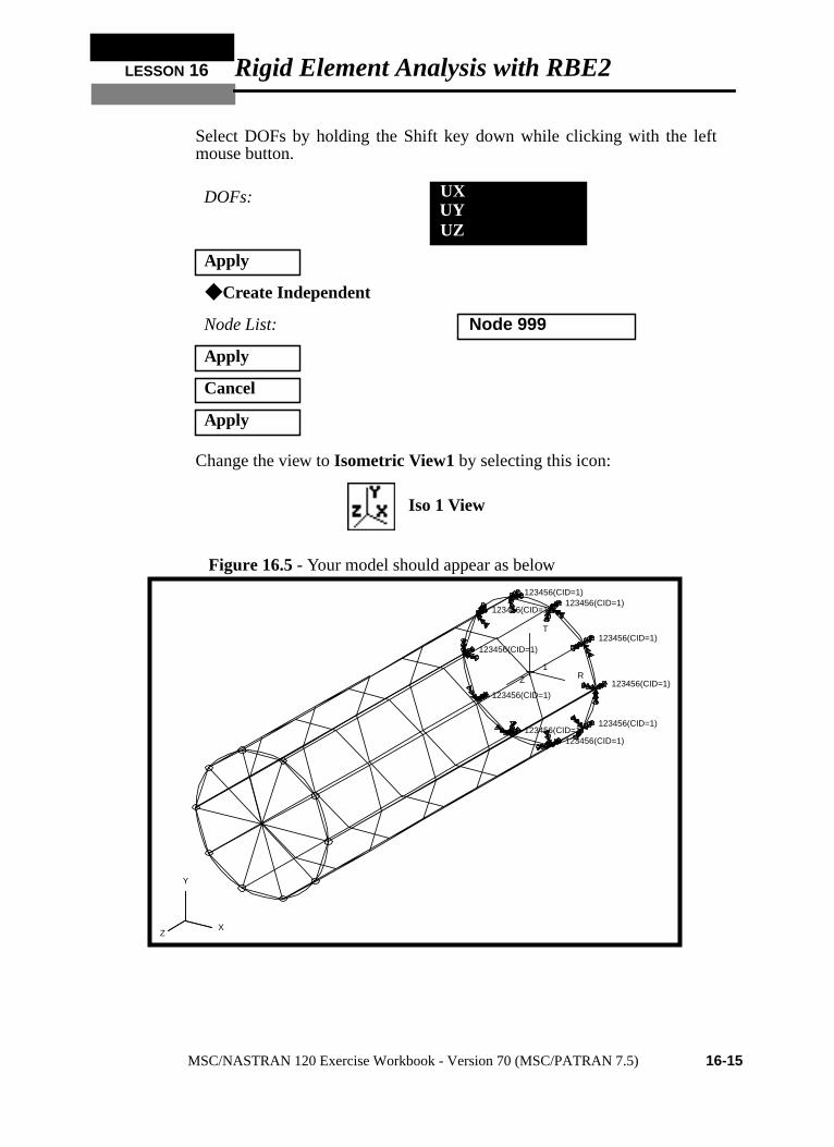
Select DOFs by holding the Shift key down while clicking with the leftmouse button.
Change the view toIsometric View1 by selecting this icon:
Figure 16.5- Your model should appear as below
DOFs:
Apply
◆ Create Independent
Node List: Node 999
Apply
Cancel
Apply
UX
UZUY
Iso 1 View
123456(CID=1)
123456(CID=1)
123456(CID=1) 123456(CID=1)
123456(CID=1)
123456(CID=1)
123456(CID=1)
123456(CID=1) 123456(CID=1)
123456(CID=1)
1R
T
Z
X
Y
Z
MSC/NASTRAN 120 Exercise Workbook - Version 70 (MSC/PATRAN 7.5) 16-15
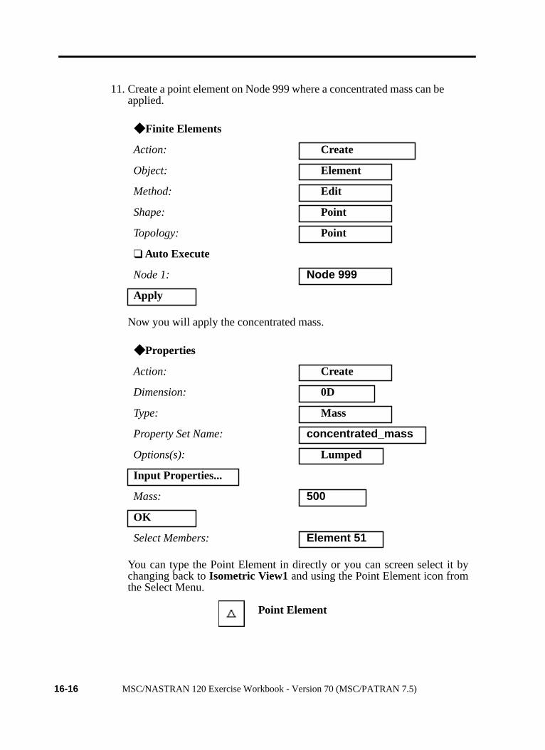
11. Create a point element on Node 999 where a concentrated mass can beapplied.
Now you will apply the concentrated mass.
You can type the Point Element in directly or you can screen select it bychanging back toIsometric View1 and using the Point Element icon fromthe Select Menu.
◆ Finite Elements
Action: Create
Object: Element
Method: Edit
Shape: Point
Topology: Point
❑ Auto Execute
Node 1: Node 999
Apply
◆ Properties
Action: Create
Dimension: 0D
Type: Mass
Property Set Name: concentrated_mass
Options(s): Lumped
Input Properties...
Mass: 500
OK
Select Members: Element 51
Point Element
16-16 MSC/NASTRAN 120 Exercise Workbook - Version 70 (MSC/PATRAN 7.5)

LESSON 16 Rigid Element Analysis with RBE2
12. Now you are ready to run the analysis.
An MSC/NASTRAN input file calledlesson16.bdfwill be generated.This process of translating your model into an input file is called theForward Translation. The Forward Translation is complete when theHeartbeat turns green.
Add
Apply
◆ Analysis
Action: Analyze
Object: Entire Model
Method: Analysis Deck
Jobname: lesson16
Solution Type...
Solution Type: ◆ NORMAL MODES
Solution Parameters...
(DeselectAutomaticConstraints.)
❒ Automatic Contraints
Mass Calculation: Coupled
Wt. -Mass Conversion = .00259
OK
OK
Apply
MSC/NASTRAN 120 Exercise Workbook - Version 70 (MSC/PATRAN 7.5) 16-17

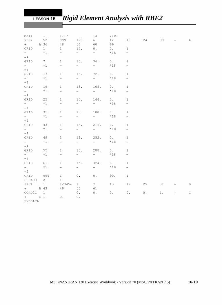
Generating an input file for MSC/NASTRAN Users:MSC/NASTRAN users can generate an input file using the data fromtable 16.1. The result should be similar to the output below.
13. MSC/NASTRAN input file:lesson16.bdf
ID SEMINAR,LESSON 16SOL 103TIME 600CENDSEALL = ALLSUPER = ALLTITLE = Normal Modes w/ RBE2ECHO = NONEMAXLINES = 999999999SUBCASE 1 METHOD = 1 SPC = 2BEGIN BULKPARAM AUTOSPC NOPARAM COUPMASS 1PARAM WTMASS .00259PARAM,NOCOMPS,-1EIGRL 1 10 0PSHELL 1 1 .125 1 1CQUAD4 1 1 1 2 8 7= *1 = *1 *1 *1 *1=3CQUAD4 6 1 7 8 14 13= *1 = *1 *1 *1 *1=3CQUAD4 11 1 13 14 20 19= *1 = *1 *1 *1 *1=3CQUAD4 16 1 19 20 26 25= *1 = *1 *1 *1 *1=3CQUAD4 21 1 25 26 32 31= *1 = *1 *1 *1 *1=3CQUAD4 26 1 31 32 44 43= *1 = *1 *1 *1 *1=3CQUAD4 31 1 43 44 50 49= *1 = *1 *1 *1 *1=3CQUAD4 36 1 49 50 56 55= *1 = *1 *1 *1 *1=3CQUAD4 41 1 55 56 62 61= *1 = *1 *1 *1 *1=3CQUAD4 46 1 61 62 2 1= *1 = *1 *1 *1 *1=3CONM2 51 999 500.
16-18 MSC/NASTRAN 120 Exercise Workbook - Version 70 (MSC/PATRAN 7.5)
LESSON 16 Rigid Element Analysis with RBE2
MAT1 1 1.+7 .3 .101RBE2 52 999 123 6 12 18 24 30 + A+ A 36 48 54 60 66GRID 1 1 15. 0. 0. 1= *1 = = = *18 ==4GRID 7 1 15. 36. 0. 1= *1 = = = *18 ==4GRID 13 1 15. 72. 0. 1= *1 = = = *18 ==4GRID 19 1 15. 108. 0. 1= *1 = = = *18 ==4GRID 25 1 15. 144. 0. 1= *1 = = = *18 ==4GRID 31 1 15. 180. 0. 1= *1 = = = *18 ==4GRID 43 1 15. 216. 0. 1= *1 = = = *18 ==4GRID 49 1 15. 252. 0. 1= *1 = = = *18 ==4GRID 55 1 15. 288. 0. 1= *1 = = = *18 ==4GRID 61 1 15. 324. 0. 1= *1 = = = *18 ==4GRID 999 1 0. 0. 90. 1SPCADD 2 1SPC1 1 123456 1 7 13 19 25 31 + B+ B 43 49 55 61CORD2C 1 0. 0. 0. 0. 0. 1. + C+ C 1. 0. 0.ENDDATA
MSC/NASTRAN 120 Exercise Workbook - Version 70 (MSC/PATRAN 7.5) 16-19

Submit the input file for analysis:
14. Submit the input file to MSC/NASTRAN for analysis.
14a. To submit the MSC/PATRAN.bdf file for analysis, find anavailable UNIX shell window. At the command promptenter: nastran lesson16.bdf scr=yes. Monitor the run usingthe UNIX pscommand.
14b. To submit the MSC/NASTRAN.dat file for analysis, find anavailable UNIX shell window. At the command promptenter: nastran lesson16 scr=yes. Monitor the run using theUNIX pscommand.
15. When the run is completed, edit thelesson16.f06file and searchfor the wordFATAL . If no matches exist, search for the wordWARNING . Determine whether existing WARNINGmessages indicate modeling errors.
16. While still editinglesson16.f06, search for the word:
E I G E N (spaces are necessary)
What are the first five modes?
Mode 1 = _________ Hz
Mode 2 = _________ Hz
Mode 3 = _________ Hz
Mode 4 = _________ Hz
Mode 5 = _________ Hz
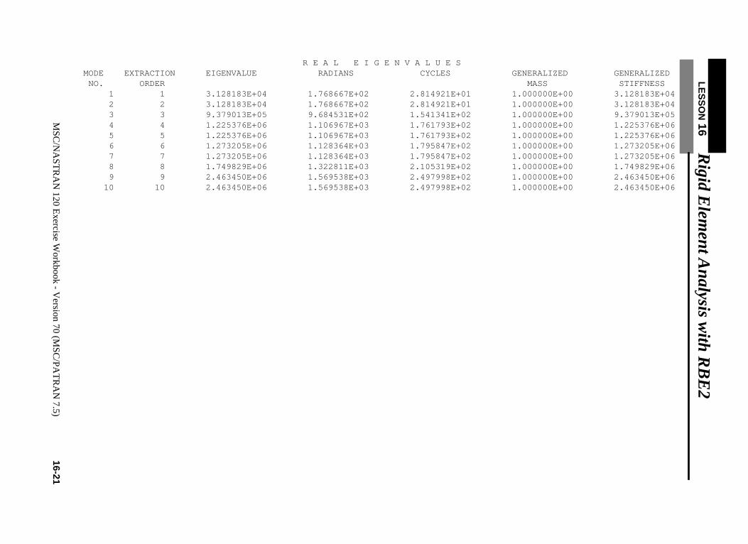
Comparison of Results:
17. Compare the results obtained in the.f06file with the results onthe following page:
16-20 MSC/NASTRAN 120 Exercise Workbook - Version 70 (MSC/PATRAN 7.5)
LES
SO
N 16 R
igid Elem
ent Analysis w
ith RB
E2
R E A L E I G E N V A L U E S MODE EXTRACTION EIGENVALUE RADIANS CYCLES GENERALIZED GENERALIZED
MS
C/N
AS
TR
AN
120 Exercise W
orkbook - Version 70 (M
SC
/PA
TR
AN
7.5)16-21
NO. ORDER MASS STIFFNESS 1 1 3.128183E+04 1.768667E+02 2.814921E+01 1.000000E+00 3.128183E+04 2 2 3.128183E+04 1.768667E+02 2.814921E+01 1.000000E+00 3.128183E+04 3 3 9.379013E+05 9.684531E+02 1.541341E+02 1.000000E+00 9.379013E+05 4 4 1.225376E+06 1.106967E+03 1.761793E+02 1.000000E+00 1.225376E+06 5 5 1.225376E+06 1.106967E+03 1.761793E+02 1.000000E+00 1.225376E+06 6 6 1.273205E+06 1.128364E+03 1.795847E+02 1.000000E+00 1.273205E+06 7 7 1.273205E+06 1.128364E+03 1.795847E+02 1.000000E+00 1.273205E+06 8 8 1.749829E+06 1.322811E+03 2.105319E+02 1.000000E+00 1.749829E+06 9 9 2.463450E+06 1.569538E+03 2.497998E+02 1.000000E+00 2.463450E+06 10 10 2.463450E+06 1.569538E+03 2.497998E+02 1.000000E+00 2.463450E+06
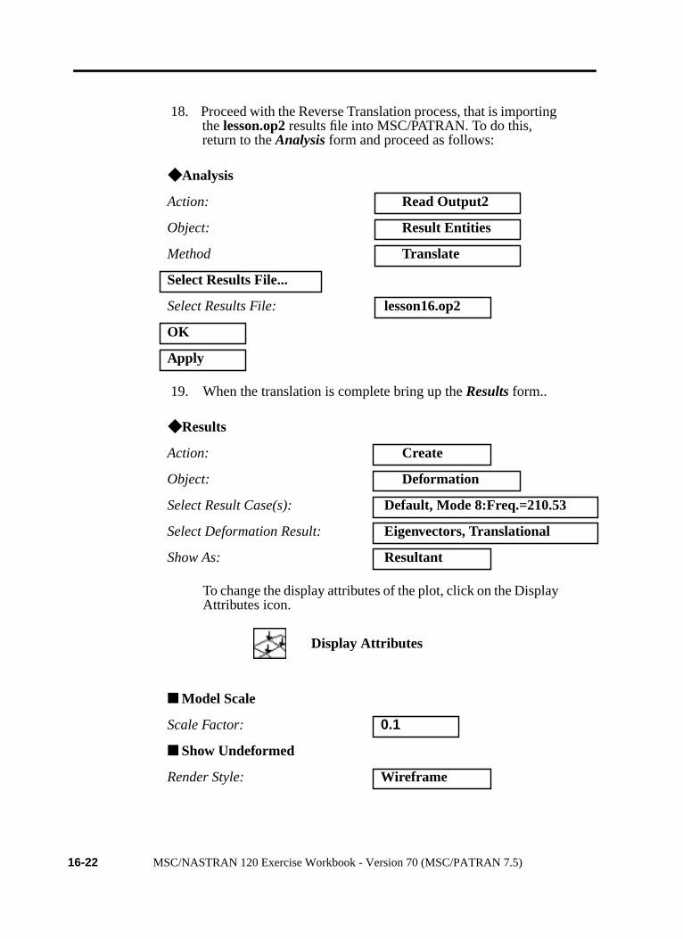
18. Proceed with the Reverse Translation process, that is importingthe lesson.op2 results file into MSC/PATRAN. To do this,return to theAnalysis form and proceed as follows:
19. When the translation is complete bring up theResults form..
To change the display attributes of the plot, click on the DisplayAttributes icon.
◆ Analysis
Action: Read Output2
Object: Result Entities
Method Translate
Select Results File...
Select Results File: lesson16.op2
OK
Apply
◆ Results
Action: Create
Object: Deformation
Select Result Case(s): Default, Mode 8:Freq.=210.53
Select Deformation Result: Eigenvectors, Translational
Show As: Resultant
■ Model Scale
Scale Factor: 0.1
■ Show Undeformed
Render Style: Wireframe
Display Attributes
16-22 MSC/NASTRAN 120 Exercise Workbook - Version 70 (MSC/PATRAN 7.5)

LESSON 16 Rigid Element Analysis with RBE2
To change the plot options, click on the Plot Options icon.
You may reset the graphics if you click on this icon:
You can go back and select anyResults Case, Fringe Results orDeformation Resultsyou are interested in.
Quit MSC/PATRAN when you are finished with this exercise.
Coordinate Transformation: CID
Select Coordinate Frame: Coord 1
Apply
Plot Options
Reset Graphics
MSC/NASTRAN 120 Exercise Workbook - Version 70 (MSC/PATRAN 7.5) 16-23

16-24MSC/NASTRAN 120 Exercise Workbook - Version 70 (MSC/PATRAN 7.5)
Mode 1 = 28.149 Hz
Mode 2 = 28.149Hz
Mode 3 = 154.13 Hz
Mode 4 = 176.18 Hz
Mode 5 = 176.18 Hz