wrm-10 - inducor.com.ar · 2 the wrm-10 is designed to accurately measure the winding resistance of...
TRANSCRIPT

2
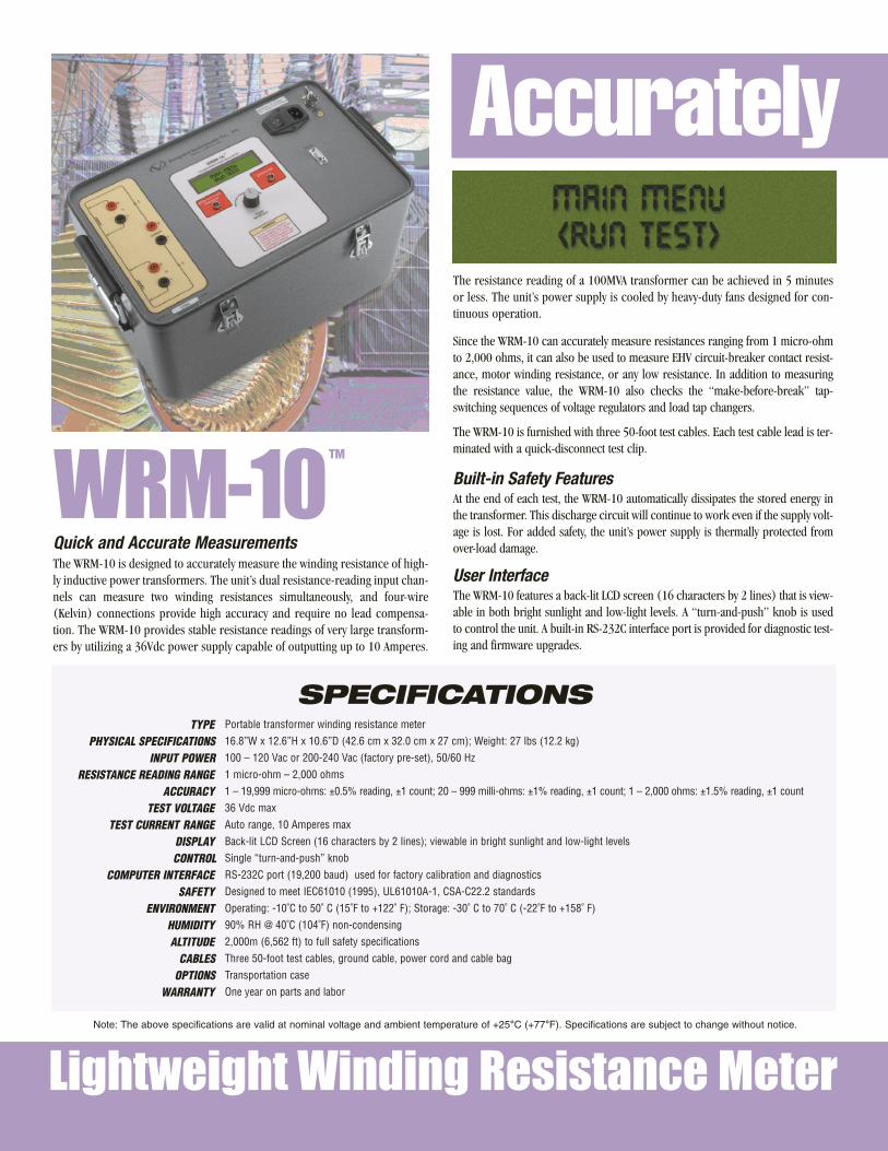
The WRM-10 is designed to accurately measure the winding resistance of high-ly inductive power transformers. The unit’s dual resistance-reading input chan-nels can measure two winding resistances simultaneously, and four-wire(Kelvin) connections provide high accuracy and require no lead compensa-tion. The WRM-10 provides stable resistance readings of very large transform-ers by utilizing a 36Vdc power supply capable of outputting up to 10 Amperes.
WRM-10
Lightweight Winding Resistance Meter
Accurately
Note: The above specifications are valid at nominal voltage and ambient temperature of +25°C (+77°F). Specifications are subject to change without notice.
The resistance reading of a 100MVA transformer can be achieved in 5 minutesor less. The unit’s power supply is cooled by heavy-duty fans designed for con-tinuous operation.
Since the WRM-10 can accurately measure resistances ranging from 1 micro-ohmto 2,000 ohms, it can also be used to measure EHV circuit-breaker contact resist-ance, motor winding resistance, or any low resistance. In addition to measuringthe resistance value, the WRM-10 also checks the “make-before-break” tap-switching sequences of voltage regulators and load tap changers.
The WRM-10 is furnished with three 50-foot test cables. Each test cable lead is ter-minated with a quick-disconnect test clip.
Built-in Safety Features At the end of each test, the WRM-10 automatically dissipates the stored energy inthe transformer. This discharge circuit will continue to work even if the supply volt-age is lost. For added safety, the unit’s power supply is thermally protected fromover-load damage.
User Interface The WRM-10 features a back-lit LCD screen (16 characters by 2 lines) that is view-able in both bright sunlight and low-light levels. A “turn-and-push” knob is usedto control the unit. A built-in RS-232C interface port is provided for diagnostic test-ing and firmware upgrades.
Quick and Accurate Measurements
TM
SPECIFICATIONSPortable transformer winding resistance meter
16.8”W x 12.6”H x 10.6”D (42.6 cm x 32.0 cm x 27 cm); Weight: 27 lbs (12.2 kg)
100 – 120 Vac or 200-240 Vac (factory pre-set), 50/60 Hz
1 micro-ohm – 2,000 ohms
1 – 19,999 micro-ohms: ±0.5% reading, ±1 count; 20 – 999 milli-ohms: ±1% reading, ±1 count; 1 – 2,000 ohms: ±1.5% reading, ±1 count
36 Vdc max
Auto range, 10 Amperes max
Back-lit LCD Screen (16 characters by 2 lines); viewable in bright sunlight and low-light levels
Single “turn-and-push” knob
RS-232C port (19,200 baud) used for factory calibration and diagnostics
Designed to meet IEC61010 (1995), UL61010A-1, CSA-C22.2 standards
Operating: -10˚C to 50˚ C (15˚F to +122˚ F); Storage: -30˚ C to 70˚ C (-22˚F to +158˚ F)
90% RH @ 40˚C (104˚F) non-condensing
2,000m (6,562 ft) to full safety specifications
Three 50-foot test cables, ground cable, power cord and cable bag
Transportation case
One year on parts and labor
TYPEPHYSICAL SPECIFICATIONS
INPUT POWERRESISTANCE READING RANGE
ACCURACYTEST VOLTAGE
TEST CURRENT RANGEDISPLAYCONTROL
COMPUTER INTERFACESAFETY
ENVIRONMENTHUMIDITYALTITUDE
CABLESOPTIONS
WARRANTY

Vanguard Instruments CompanyReliability Through Instrumentation
Measure Winding Resistances ofHighly Inductive Power Transformers
PowerReceptacle
ModuleWarning
Indicators
RS-232CInterface
Back-lit LCD Screen(16 characters by 2 lines)
FunctionControl Knob
ResistanceInput
Channel #1
ResistanceInput
Channel #2
Ordering InformationWRM-10TM Winding Resistance Meter
WRM-10TM, Cable Part No: WRM-10
WRM-10TM Shipping Case Part No: WRM-10 Case
50-ft Test Cable Part No: WRM Test Cable
CurrentOutput
Connectors
Connections
• Auto discharge circuit for operator safety
• Auto current ranging from 10 mA to 10 A
• Digital resistance reading from 1 micro-ohm to 2,000 ohms
• Weighs 27 lbs (12.2 Kg)FEAT
URES
RVFeb10

Vanguard Instruments Company, Inc.
Vanguard Instruments Co., (VIC), was founded in 1991.Currently, our 28,000 square-foot facility houses Administration,Design & Engineering, and Manufacturing operations. From itsinception, VIC’s vision was, and is to develop and manufactureinnovative test equipment for use in testing substation EHV circuitbreakers and other electrical apparatus.
The first VIC product was a computerized circuit-breaker analyz-er, which was a resounding success. It became the forerunner ofan entire series of circuit-breaker test equipment. Since its begin-ning, VIC’s product line has expanded to include microcomput-er-based, precision micro-ohmmeters, single and three-phasetransformer winding turns-ratio testers, winding-resistancemeters, transformer tap-changing controllers, megaohm resist-ance meters, and a variety of other electrical utility mainte-nance support products.
VIC’s performance-oriented products are well suited for the util-ity industry. They are rugged, reliable, accurate, user friendly, andmost are computer controlled. Computer control, with innovativeprogramming, provides many automated testing functions. VIC’sinstruments eliminate tedious and time-consuming operations,while providing fast, complex, test-result calculations. Errors arereduced and the need to memorize long sequences of procedur-al steps is eliminated. Every VIC instrument is competitivelypriced and is covered by a liberal warranty.
Vanguard products are available from:
Vanguard Instruments Company, Inc.1520 S. Hellman Ave. • Ontario, California 91761 USA • P 909-923-9390 • F 909-923-9391
www.vanguard-instruments.com