wp4.1 global architecture definition & requirements · document history version date author...
TRANSCRIPT

Multimodality for people and goods in urban areas
FP7 . CP 284906
WP4.1 – Global architecture definition & requirements
December 2011
Editor: Dirk Beckman / DLR
License
This work is licensed under the Creative Commons Attribution-NonCommercial- NoDerivs 2.0 License.
To view a copy of this license, visit http://creativecommons.org/licenses/by-sa/3.0/ or send a letter to Creative
Commons, 171 Second Street, Suite 300, San Francisco, California, 94105, USA.
Project co-funded by the European Commission within the Seventh Framework Programme (2008-2013)
Copyright by the partners of the Instant Mobility Consortium
Project funded by the European Commission under the 7th European Framework
Programme for RTD - ICT theme of the Cooperation Programme.

Instant Mobility WP4.1
Global architecture definition & requirements 2
Instant Mobility WP4.1 Global architecture definition & requirements
WP4.1 Deliverable title
Authors
Dirk Beckmann - DLR Tobias Schlauch – DLR Daniel Thielen - DLR
Short Description
This deliverable will describe the global architectural requirements applicable to the seven set of components of the Instant Mobility usage platform in such a way as to guarantee internal interoperability and consistency between these sets of components.
Dissemination level (select)
PU Public
Date
31 December 2011
Status
Deliverable (final version 1.0)
Contributions by:
Dirk Beckmann - DLR Tobias Schlauch – DLR Daniel Thielen - DLR
Internal review by
Andrea Bragagnini - Telecom Italia
Internally accepted by
Patrick Gatellier (WP4 leader)
Date of acceptance 19 january 2012
Document history
Version Date Author /Reviewer Description
0.01 12.08.2011 Dirk Beckmann Initial Version / document structure
0.06 12.12.2011 Dirk Beckmann Integrating input / finalizing for first P2P review

Instant Mobility WP4.1
Global architecture definition & requirements 3
Deliverable Abstract This deliverable will describe the global architectural requirements applicable to the seven set of components of the Instant Mobility usage platform in such a way as to guarantee internal interoperability and consistency between these sets of components. This document also serves as a guideline to the project partners that are involved in WP3 and WP4 to guide and standardize the approach within the project. At the time of writing this is the functional decomposition of the scenarios in WP3 and the workflow transition (handover) to WP4.

Instant Mobility WP4.1
Global architecture definition & requirements 4
Table of Content
1. INTRODUCTION .......................................................................................................................................... 5
1.1 INTRODUCTION TO THE WORK OF WP4.1 ......................................................................................................... 5 1.2 ORGANISATION ........................................................................................................................................... 6 1.3 INTENDED AUDIENCE .................................................................................................................................... 7 1.4 TERMINOLOGY ............................................................................................................................................ 7 1.5 ABBREVIATIONS ........................................................................................................................................... 8
2. TECHNOLOGY TRADE-OFFS ........................................................................................................................ 9
2.1 CORE PLATFORM ALIGNMENT ......................................................................................................................... 9 2.2 LEGACY SYSTEMS ......................................................................................................................................... 9 2.3 TRADITIONAL VS. INNOVATIVE PARADIGMS ........................................................................................................ 9 2.4 AVAILABILITY AND ACCEPTANCE AMONGST PROJECT PARTNERS .............................................................................. 9
3. ARCHITECTURE DEFINITION APPROACH .................................................................................................. 10
3.1 BASIC ARCHITECTURE CONSIDERATIONS .......................................................................................................... 10 3.2 DECOMPOSITION APPROACH .................................................................................................................. 12
3.2.1 Process decomposition framework ................................................................................................. 12 3.2.2 Use case modelling technique ........................................................................................................ 14 3.2.3 The overall domain decomposition process ................................................................................... 16
4. ENABLER SET DOMAIN-DECOMPOSITION ............................................................................................... 18
4.1 MULTIMODAL TRAVEL MAKE EASY ...................................................................................................... 18 4.1.1 End-to-end itinerary planning ........................................................................................................ 19
5. APPENDIX ................................................................................................................................................. 28
5.1 TOOL SURVEY FORM................................................................................................................................... 28
Table of Figures Figure 1: Instant Mobility work flow diagram ..................................................................................................... 5 Figure 2: Work flow in WP4 ............................................................................................................................... 6 Figure 3: Typical Service Oriented Architecture .............................................................................................. 10 Figure 4: Thick server / thin client concept ...................................................................................................... 10 Figure 5: Functional architecture ..................................................................................................................... 11 Figure 6: Technical architecture ...................................................................................................................... 11 Figure 9: Process stack ................................................................................................................................... 12 Figure 10: Layered use case structure ............................................................................................................ 15 Figure 11: Overall domain decomposition approach ....................................................................................... 16 Figure 12: Pre-trip phase ................................................................................................................................. 18 Figure 13: On-trip phase .................................................................................................................................. 19
Instant Mobility WP4.1
Global architecture definition & requirements 5
1. Introduction
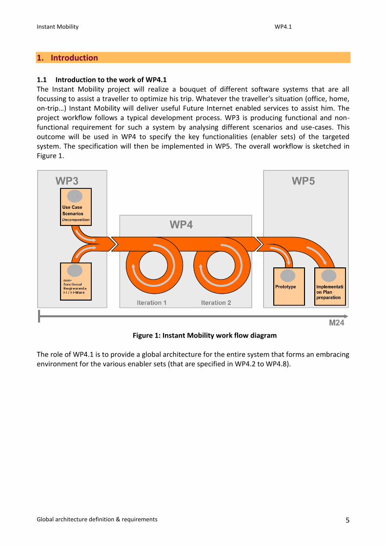
1.1 Introduction to the work of WP4.1 The Instant Mobility project will realize a bouquet of different software systems that are all focussing to assist a traveller to optimize his trip. Whatever the traveller's situation (office, home, on‐trip…) Instant Mobility will deliver useful Future Internet enabled services to assist him. The project workflow follows a typical development process. WP3 is producing functional and non-functional requirement for such a system by analysing different scenarios and use-cases. This outcome will be used in WP4 to specify the key functionalities (enabler sets) of the targeted system. The specification will then be implemented in WP5. The overall workflow is sketched in Figure 1.
Figure 1: Instant Mobility work flow diagram The role of WP4.1 is to provide a global architecture for the entire system that forms an embracing environment for the various enabler sets (that are specified in WP4.2 to WP4.8).

Instant Mobility WP4.1
Global architecture definition & requirements 6
1.2 Organisation The work in WP4 and especially in WP4.1 is a true nexus in the project. It is clearly embedded in the overall process as sketched above (s. 1.1).
Figure 2: Work flow in WP4 The development of the global architecture follows the principle of iterative development in two major lines of work: Firstly WP4.1 will provide a global architecture that forms a founding ground for the enabler sets that will be developed in WP4 (WP4.2...WP4.8). Secondly WP4.1 will align those developments and merge them into the common concepts of the architecture. Figure 2 illustrates the iterative and parallel specification process in WP4. The work in WP4.1 consists of two main aspects accordingly. The first is to prepare the global architecture that is suitable to house the enabler sets and to provide guidelines for the iterative refinement of their specification. This deliverable is documenting this process and is reflecting the specification process in WP4.1. D4.1 can be considered as the first document in WP4 and sets basic guidelines for the specification process. The definition of the global architecture is described in this document. The adjoining enabler sets will be tangent on a sufficient level to derive necessary considerations and requirements for the global architecture. Some of the assumptions are will be revised in the parallel requirements definition process (WP3). So the consolidated final outcome itself is documented in D4.16 which will contain the full outcome of the specification process. This document will explain the methodology of the architecture definition process in chapter 2. The heart of the architecture definition process is the functional decomposition of the specific enabler sets in chapter 4. Instant Mobility is deeply embedded into the European FI-PPP Program and will not implement all functionality within the project. Even though these entities are specified in WP4, it is necessary to identify non-domain specific functions that can be realized outside the project (the project FI-WARE will implement this functionality). Chapter 2.1 will define functions that can (or must) be interfaced from outside the scope of this project. When defining a software landscape with many partners in a heterogeneous environment it is mandatory to consider non-functional aspects of the definition process itself. Chapter 2 explains non-functional design decisions such as the election of relevant tools.

Instant Mobility WP4.1
Global architecture definition & requirements 7
1.3 Intended audience This document describes the architecture of Instant Mobility in technical and organisational terms. Therefore it is aimed primarily at partners that are involved in this process (WP4.2…WP4.8) As it documents the efforts and decisions to define basic aspects of the Instant Mobility project it is also of interest for all technical partners involved in WP5. The definitions made in this document are crucial for the implementation in WP5. The collaboration with other projects of the FI-PPP program (and especially FI-WARE) is coordinated through WP2. So this document will provide WP2 with specific functionality that will be realized outside this project. Furthermore this document is aiming at and the European Commission as well as any project or incentive taken to adopt Instant Mobility concepts within FI-PPP.
1.4 Terminology This document considers the technical specification of the Instant Mobility system and especially the underlying architecture of the envisioned system. The terms used in this document are therefore aligned with the technical terms of this field of work. Major deviations between the terminology of the transport and mobility domain and the technical used in this document are enlightened in this chapter. Services: In general this a technical autonomous entity (software) that provides well specified functionality through a well-defined interface. A service can be a small algorithm or can be comprised out of other services to provide a complex functionality. This may not be confused with the term service in the transport and mobility domain that refers mainly to a full solution e.g. Route Guidance or eCall. Consumer: In a service oriented architecture there will be many services that provide some kind of functionality that is used by other services. The relation between services that consume data from other services is called consumer. This may not be confused with the end-user role in the business process considerations. Service provider: Services that provide some functionality to be used by other services are service provider. This may not be confused with provider of a full business case (see ambiguity of the term service above).

Instant Mobility WP4.1
Global architecture definition & requirements 8
1.5 Abbreviations BPEL Business Process Execution Language BPEL4People WS-BPEL Extension for People BPMN Business Process Model and Notation CP Core Platform FI PPP Future Internet Public Private Partnership FP7 Seventh Framework Programme ICT Information and communications technology iOS Proprietary operating system of Apple’s mobile phones ITS Intelligent transportation system POI Point of Interest RTD Research & Technical Development SOA Service-oriented architecture SOAP Simple Object Access Protocol UML Unified Modelling Language WAC Wholesale Applications Community WSDL Web Services Description Language

Instant Mobility WP4.1
Global architecture definition & requirements 9
2. Technology trade-offs
On the one hand the definition process of the Instant Mobility architecture is deeply impacted by many non-functional constraints that result from the projects embedding into the FI-PPP project landscape and especially the collaboration with the development of the core platform needs to be considered. On the other hand the timeline of the specification process is tight and does not allow strict sequential transition between the requirements definition process and the specification. So it is necessary to select some concepts, tools and paradigms more or less independent from the availability of functional requirements. The selection will impact especially the specification and implementation part of the Instant Mobility platform. The aspects that were considered and the methodology to make the selection are described in this section. This section was delegated to Ericsson and a few bullet points were defined to outline their expected contribution. As they have left the project, this chapter lacks content.
2.1 Core Platform alignment FI-WARE Principles SOA Agilefant
2.2 Legacy Systems IBM SOAMIG approach
2.3 Traditional vs. innovative paradigms Innovative FI, traditional platform
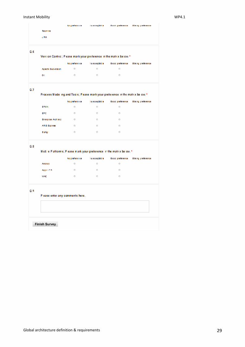
2.4 Availability and acceptance amongst project partners Description of the tool survey and its outcome See also section 5.1 General Development Tools: Standard office software, Wiki engine & change management, Rational DOORS, IRQA Change Management: Agilefant, Redmine, JIRA Version Control: Apache Subversion, Git Process Modelling and Tools: BPMN, EPC, Enterprise Architect, ARIS Express, BizAgi Mobile Platforms: Android, Apple iOS, WAC SOA
WSDL vs. other options
BPEL vs. BPMN for technical orchestration of business processes Mobile Application Frameworks

Instant Mobility WP4.1
Global architecture definition & requirements 10
3. Architecture definition approach
Instant Mobility will use the Service-Orientation as paradigm to define the architecture. This will be assumed a generic concept and emboss both the architecture definition process and the specification of the enabler sets in this work package. To understand the applicability of this concept it is necessary to start with initial ideas that will be refined through the specification process and will be outlined in full in later deliverables such as D4.16. This section is explaining core ideas how to approach the architecture and the embedding of the enabler sets. A service-oriented architecture (SOA) is an architecture paradigm that has its origins in the design of distributed systems and helped to structure and use the complex landscapes. The SOA is typically aligned to the business process in different abstraction layers. The SOA main principles of the SOA are to create services that can be re-used by other services which can create a hierarchical services structure that gains in abstraction by enriching a service with less abstract services. The technical realisation of a SOA in this project is a close relation to other concepts and paradigms. E.g. SOA need mechanisms to orchestrate services on an operative level. The selected concepts and the reason why to choose them are described in section 2.
3.1 Basic architecture considerations Regardless of the technical realisation services will encapsulate a given functionality and will be re-used by other. In general the design of such a service network is achieved by a function decomposition processes the analyses the requirements and identifies meaningful services to compose the desired functionality. In this project the situation is more complex as Instant Mobility is relating to the core platform (FI-Ware) to develop generic enablers and the specification process is branched into seven independent functional decompositions (see Figure 2). So it is necessary to align the specification with both the core platform and the amongst the functional decomposition streams within WP4. Figure 3 illustrates this idea; there will be services (generic enablers) that are specified and developed by the core platform and can be (re-)used by various services within Instant Mobility.
Figure 3: Typical Service Oriented Architecture
Figure 4: Thick server / thin client concept
At this point of time there is no common platform that motivates SOA on mobile devices. The design of mobile devices usually follows other maxims such as power consumption and weight. Therefore the typical overhead of an application server that forms a runtime environment for

Instant Mobility WP4.1
Global architecture definition & requirements 11
services is not found on those devices. Even in-car pcs that have more resources in terms of computation power and memory tend to stick to more traditional architectures. Instant Mobility will use these devices and a truly distributed SOA seems not to be feasible at this point. To spread functionality between mobile devices and the Instant Mobility Platform the functional part in the mobile device will be based on the devices proprietary architecture and communicate by traditional channels (e.g. SOAP) with the Instant Mobility services in a typical client server architecture. Figure 4 illustrates the relation between a mobile device that has a dedicated operating system (Android) and the server. In detail there will be trade-off between the functionality that is keep on the server side and autonomous algorithms that are deployed to the nomadic device. In practice there needs to be a good understanding of the functionality and the underlying mechanisms that support the specific functionality. This can be used to provide well thought out mechanisms (“fall-back”) in case a specific technical resource is temporary not available. The considerations regarding the service degradation will be dealt with in the specification of the enabler sets. A tradition software architecture approach considers a three tier design pattern that identifies a model, a view and a control layer (MVC-architecture). The purpose of this is to decouple these three main technical entities and allows e.g. to define clear interfaces, alleviates re-use and reduces effort in maintenance. For the architecture it is quite evident how to arrange the layers of such a structure:
Presentation layer (mobile device applications, nomadic devices application, web portal applications, …)
Business process layer (journey application, drivers application, …)
Service layer (domain specific atomic services + atomic core service) Such architecture can be displayed in both a functional and a technical layered model.
Figure 5: Functional architecture
Figure 6: Technical architecture The functional architecture (see Figure 5) illustrates the functional composition of the Instant Mobility platform. In essence this picture shows that core services facilitate the functionality of the FI technologies. Those services are used to support the domain specific services. They serve as a pool of functionality that can be accessed by the enabler sets that function as the core engine of an Instant mobility application that is visualised on a mobile/nomadic device. There are auxiliary functions necessary such as administration. This is also reflected as a vertical functionality. Figure 6 illustrates the same architecture model in a different angle. The image illustrates the technical composition of the Instant Mobility platform and also reflects the three tiers as

Instant Mobility WP4.1
Global architecture definition & requirements 12
described above. The main difference here is the introduction of a service bus that forms the central nerve system of the control layer.
3.2 Decomposition approach
The following sections explain the selected approach for domain decomposition which is used to determine the technical services and their operations. This approach mainly follows the suggestions of IBMs “Process-oriented modelling for SOA” *ProcessModellingSOA]1 and uses a process model which is aligned to the presentation, business, and service layer of the reference architecture. I.e. shortly: we determine the essential processes of every layer and their interactions. Processes of the business layer represent technical services and the analysis of the process flow identifies potential service operations. First the process decomposition framework is explained including the different process types, the underlying layering principle, and the mapping of process types to layers of the reference architecture. Then we show a suitable UML (Unified Modelling Language) use case modelling technique which can be used to perform the process decomposition accordingly. Finally, we present the overall domain decomposition process.
3.2.1 Process decomposition framework
The framework identifies different process types and organises them in accordance to a process stack (Figure 7). This principle supports independence of processes and re-usability of lower-level processes across higher-level processes. Every individual process is assigned to exactly one layer. Processes of a specific layer can only invoke or subscribe to events from processes in lower layers. In addition, they should also be unaware of processes in the upper layer. The process identification is performed in top-down manner. In the following we discuss the individual process layers.
Figure 7: Process stack User experience process This layer is just a virtual layer and has no equivalent within the basic architecture. However, this layer sets the context for processes in lower layers and describes the process environment including all non-automated activities. What is in WP3/WP4 user application processes
1 ProcessModellingSOA: see https://www.ibm.com/developerworks/library/ar-procmod1/

Instant Mobility WP4.1
Global architecture definition & requirements 13
User application processes The user application process layer is associated with the presentation layer of the basic architecture. The processes of this layer show how end-user applications (e.g., smart phone or web portal applications) interact with the underlying business processes. These applications maintain the dialogue with the users (e.g., internal, external or system users) and hold the required session state. The purpose of this layer is to gather all required information to run a process or transaction in the underlying layers. Thus, user application processes describe the behaviour of a specific application which has to be clearly separated from the business process layer. End-user applications call long-running processes in a fire-and-forget manner and will not wait for a response (asynchronous call). Additionally, they call short-running processes using a request-response interaction (synchronous call). Long-running processes Long-running processes form the upper part of the business process layer of the basic architecture. They involve at least one of the following steps:
- They wait for an external event. - They include an activity which is performed by a person. - They include an activity whose processing might take a long time.
These processes can be invoked by user application processes or by an event which results from a short-running process. Long-running processes can be considered re-usable across these two types of processes. Human activities From the process modelling point of view human activities are clearly part of the business process layer. They are initiated by a long-running process and typically start when a person (e.g., an employee of an enterprise or a technical expert) selects a task from the work list. A human activity itself is represented as a single process and might involve the invocation of short-running processes or automated activities. Current technical solutions are able to mediate the invocation event and provide additionally required user interfaces. In addition, the standardisation effort BPEL4People [BPEL4People]2 of the OASIS aims to extend BPEL [BPEL]3 by inclusion of human interactions. Short-running processes Short-running processes form the lower part of the defined business process layer. They are always non-conversational and provide a result (almost) immediately by orchestration of a number of fully automated service operations. The processes of this layer can be invoked by user application processes, long-running processes or human activities. Some scenarios might require that a short-running process calls a long-running process. This could for example be necessary in an order management scenario in which:
- the short-running process represents an order transaction and - the long-running process represents the fulfilment of the order.
2 BPEL4People: http://www.oasis-open.org/committees/tc_home.php?wg_abbrev=bpel4people
3 BPEL: http://www.oasis-open.org/committees/tc_home.php?wg_abbrev=wsbpel
Instant Mobility WP4.1
Global architecture definition & requirements 14
A direct call of the long-running fulfilment order process would break the layering principle. To avoid this, the transaction process generates an event which indicates the arrival of a new order. The fulfilment process listens and acts upon this event. Thus, the short-running process is unaware of the upper layer and the layering principle is still kept. Automated activities The automated activities layer consists of the single services and provides these building blocks to the upper layers. An automated activity can be considered as an atomic step, e.g. a call to an external system, a data operation (read, create, update, delete) or a validation operation. Thus, they can be considered as candidate service operations. The automated activity layer corresponds to the services layer of the basic architecture.
3.2.2 Use case modelling technique
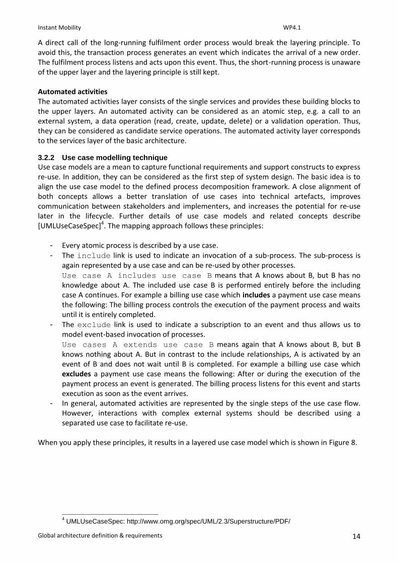
Use case models are a mean to capture functional requirements and support constructs to express re-use. In addition, they can be considered as the first step of system design. The basic idea is to align the use case model to the defined process decomposition framework. A close alignment of both concepts allows a better translation of use cases into technical artefacts, improves communication between stakeholders and implementers, and increases the potential for re-use later in the lifecycle. Further details of use case models and related concepts describe [UMLUseCaseSpec]4. The mapping approach follows these principles:
- Every atomic process is described by a use case. - The include link is used to indicate an invocation of a sub-process. The sub-process is
again represented by a use case and can be re-used by other processes. Use case A includes use case B means that A knows about B, but B has no knowledge about A. The included use case B is performed entirely before the including case A continues. For example a billing use case which includes a payment use case means the following: The billing process controls the execution of the payment process and waits until it is entirely completed.
- The exclude link is used to indicate a subscription to an event and thus allows us to model event-based invocation of processes. Use cases A extends use case B means again that A knows about B, but B knows nothing about A. But in contrast to the include relationships, A is activated by an event of B and does not wait until B is completed. For example a billing use case which excludes a payment use case means the following: After or during the execution of the payment process an event is generated. The billing process listens for this event and starts execution as soon as the event arrives.
- In general, automated activities are represented by the single steps of the use case flow. However, interactions with complex external systems should be described using a separated use case to facilitate re-use.
When you apply these principles, it results in a layered use case model which is shown in Figure 8.
4 UMLUseCaseSpec: http://www.omg.org/spec/UML/2.3/Superstructure/PDF/

Instant Mobility WP4.1
Global architecture definition & requirements 15
Figure 8: Layered use case structure Every use case should be described by the following properties:
- Unique name: Used to uniquely identify the use case. - Goal: Describes what should be achieved. - Trigger: Describes which event or action initiates the use case. - Primary actor: Fulfils the goals by using the provided functionalities. - Pre-conditions: Describes conditions which have to be fulfilled to perform the use case. - Post-conditions: Describes the result and conditions after the use case has been
completed. - Flow: Describes the detailed process flow using the BPMN notation. - Summary: A summary of the process flow. - Dependencies: Describes dependencies on other use cases.
Finally, we discuss some specifics when mapping processes to use cases:
- The user experience process layer describes the system context but no system behaviour. Thus, no corresponding system use case needs to be created for these processes.

Instant Mobility WP4.1
Global architecture definition & requirements 16
- User application processes describe how the user application interacts with the system and therefore can be directly mapped to a “traditional” use case.
- Long- and short-running processes are part of the business process layer and are usually automated by a process orchestration engine. These processes are always activated by other use cases and involve no direct user interaction. Consequently, there exists no primary actor.
- Long-running process use cases clearly represent the orchestration of activities within the use case model. This representation does not conform to traditional use case identification rules. However, the same descriptive information is required. In this context the meaning of include and extend relationships needs to be slightly extended:
o include: “call and wait until completion” or “call and continue”.
o extend: “initiate the process” or “continue the process”. You should clearly indicate the concrete meaning within the use case description.
- Similar to consumer processes, human activities describe user interactions with the system. Corresponding use cases should focus on the user interaction scope. The outputs and post conditions have to be handled by the long-running use case which activated the human activity.
3.2.3 The overall domain decomposition process
The domain decomposition process (Figure 9) consists of two essential steps which basically can be executed in parallel:
- Applying the previously described process-oriented modelling approach: This step provides the top-down view of system.
- Analysing existing systems: This step provides the bottom-up view of the system.
Figure 9: Overall domain decomposition approach Process-oriented Modelling: The result of this step is a comprehensive service model for every development scenario which describes all required processes and a list of generic candidate service operations.
- Identify the user experience process: The user experience process describes how the user interacts with the system and helps to identify initial user application use cases. It should be described by a BPMN flow and a short summary.
- Perform the use case analysis: The use case analysis is driven by the initially identified user application use cases which result from the user experience process. The process flow diagrams of the user application use cases help to conduct further use cases of lower layers . The result of this step is a service model which in trun is represented by the use case model and summarizes all processes, automated activities, and their connections.

Instant Mobility WP4.1
Global architecture definition & requirements 17
Analysis of existing systems: A list of technical services and their operations is just the first step. In addition, we need to identify:
the logical components which provide these operations and
on which basis (e.g., existing legacy systems) these components can be implemented. These details directly correspond to the service component and the operational layer of the basic architecture. The information needs to be obtained from the partners who already implemented similar systems and should be addressed in WP3/WP4. In addition, the provided cross-cutting functionalities of the FI-WARE [FI-WAREProductVision]5 project have to be taken into account. This step complements the service model with information on how service operations are actually implemented.
5 FI-WAREProductVision: http://forge.fi-ware.eu/plugins/mediawiki/wiki/fiware/index.php/FI-
WARE_Product_Vision
Instant Mobility WP4.1
Global architecture definition & requirements 18
4. Enabler set domain-decomposition
The following sections show the functional decomposition at the example of the multi-modal travelling scenario. In particular, the following artefacts have to be created:
- User experience process: The user experience process explains the context of the specific enabler set and represents the view of the user.
- Use Case Model: The use case model shows in detail the identified processes and service operations and how they have been conducted. It is structured in accordance to the identified set of development scenarios. I.e. every identified logical service of the development scenario description is specified by a corresponding use case model. Use cases of other services are referenced as required. The example uses the following pattern to uniquely identify use cases: UC<Development Scenario Number><Service Letter>.<Use Case
Number>. The use case number gets just incremented for every new use case. For further details see section 3.2 which explains the domain-decomposition approach in detail.
4.1 Multimodal Travel Make Easy
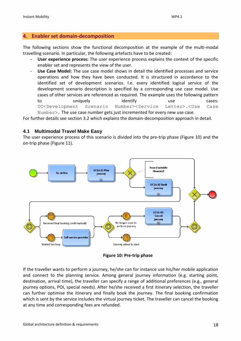
The user experience process of this scenario is divided into the pre-trip phase (Figure 10) and the on-trip phase (Figure 11).
If the traveller wants to perform a journey, he/she can for instance use his/her mobile application and connect to the planning service. Among general journey information (e.g. starting point, destination, arrival time), the traveller can specify a range of additional preferences (e.g., general journey options, POI, special needs). After he/she received a first itinerary selection, the traveller can further optimise the itinerary and finally book the journey. The final booking confirmation which is sent by the service includes the virtual journey ticket. The traveller can cancel the booking at any time and corresponding fees are refunded.
Figure 10: Pre-trip phase

Instant Mobility WP4.1
Global architecture definition & requirements 19
The system supports the traveller in various ways during the journey. For instance the traveller is continuously informed about itinerary changes (e.g., plane cancelations, traffic congestions), supported in case of unexpected journey interruptions, guided during change of transportation modes, or pointed to events and places which might be from interest for him/her.
Figure 11: On-trip phase
Figure 12: Service model The following sections present the identified use cases in detail.
4.1.1 End-to-end itinerary planning
Figure 13 shows the identified use cases of the planning service. Related use cases have been referenced accordingly. In general, the BPMN flows use the lane “Channel” to model communication with the end-user`s application (e.g., mobile phone or web portal application).
Instant Mobility WP4.1
Global architecture definition & requirements 20
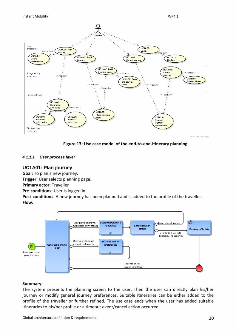
Figure 13: Use case model of the end-to-end-itinerary planning
4.1.1.1 User process layer
UC1A01: Plan journey
Goal: To plan a new journey. Trigger: User selects planning page. Primary actor: Traveller Pre-conditions: User is logged in. Post-conditions: A new journey has been planned and is added to the profile of the traveller. Flow:
Summary: The system presents the planning screen to the user. Then the user can directly plan his/her journey or modify general journey preferences. Suitable itineraries can be either added to the profile of the traveller or further refined. The use case ends when the user has added suitable itineraries to his/her profile or a timeout event/cancel action occurred.
Instant Mobility WP4.1
Global architecture definition & requirements 21
Includes: UC1A.04 Define preferences, UC1A.06 Determine itineraries UC1A02: Book journey
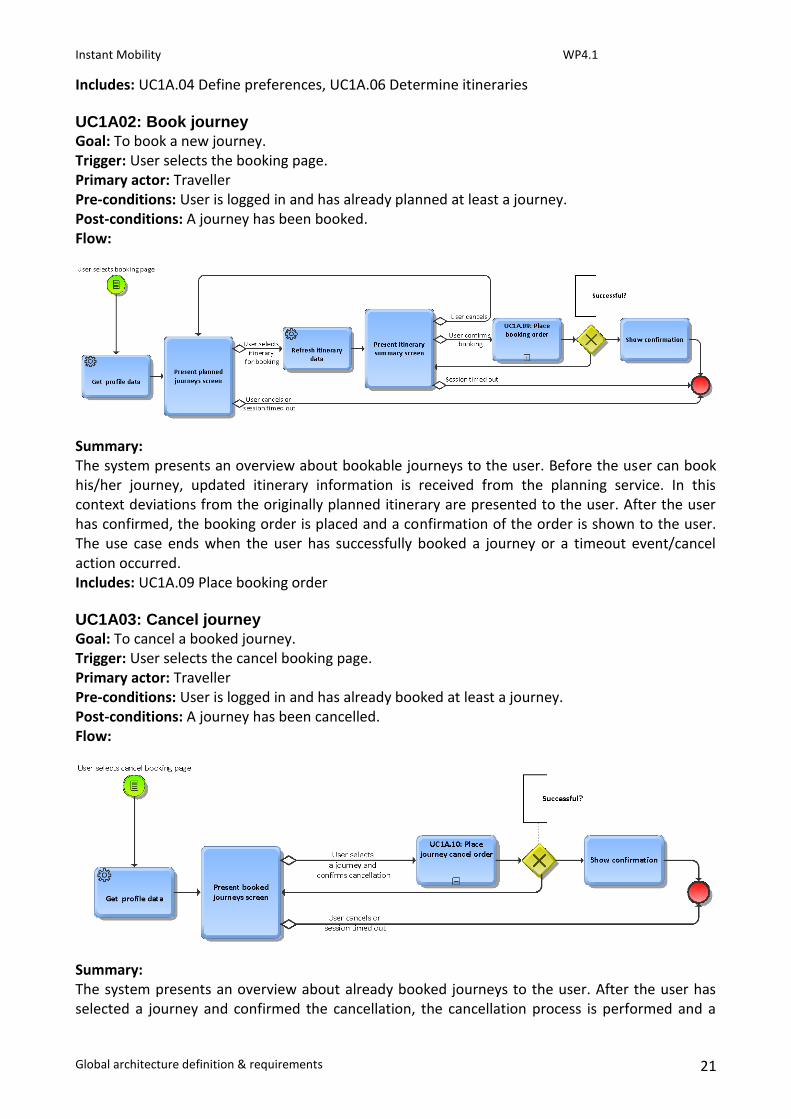
Goal: To book a new journey. Trigger: User selects the booking page. Primary actor: Traveller Pre-conditions: User is logged in and has already planned at least a journey. Post-conditions: A journey has been booked. Flow:
Summary: The system presents an overview about bookable journeys to the user. Before the user can book his/her journey, updated itinerary information is received from the planning service. In this context deviations from the originally planned itinerary are presented to the user. After the user has confirmed, the booking order is placed and a confirmation of the order is shown to the user. The use case ends when the user has successfully booked a journey or a timeout event/cancel action occurred. Includes: UC1A.09 Place booking order UC1A03: Cancel journey
Goal: To cancel a booked journey. Trigger: User selects the cancel booking page. Primary actor: Traveller Pre-conditions: User is logged in and has already booked at least a journey. Post-conditions: A journey has been cancelled. Flow:
Summary: The system presents an overview about already booked journeys to the user. After the user has selected a journey and confirmed the cancellation, the cancellation process is performed and a

Instant Mobility WP4.1
Global architecture definition & requirements 22
confirmation is shown to the user. The use case ends when the user has successfully cancelled a journey or a timeout event/cancel action occurred. Includes: UC1A.10: Request journey cancellation UC1A04: Define preferences
Goal: To define general journey preferences. Trigger: User selects preferences page or is redirected to it. Primary actor: Traveller Pre-conditions: The user is logged in. Post-conditions: A valid user profile exists. Flow:
Summary: The use case lets the traveller define his/her journey preferences. First, all relevant options/ categories and the existing profile data are retrieved. Then a form with the existing or default settings is presented and the user can modify his/her preferences accordingly. When the user confirms his/her changes, the profile information is updated. The use case ends when the user has successfully modified the profile data or a timeout event/cancel action occurred. Includes: -
UC1A05: Login
Goal: To log the user in. Trigger: User selects the login page. Primary actor: Traveller Pre-conditions: - Post-conditions: The user is logged in. Flow:

Instant Mobility WP4.1
Global architecture definition & requirements 23
Summary: The system presents the login screen. Then the user can either log into the system or create a new profile. When the user has provided his/her authentication information, the system performs the authentication process. The use case ends when the user is successfully logged into the system or a timeout event/cancel action occurred. Includes: UC1A11: Register UC1A11: Register
Goal: To register a new user. Trigger: User is redirected to the registration page. Primary actor: Traveller Pre-conditions: - Post-conditions: A new user profile has been created. Flow:
Summary: The system presents the registration screen. Then the user can provide his/her initial profile data (e.g., name, address). When the user confirms his/her information a corresponding profile is created and the user is registered. The use case ends when the user is successfully registered or a timeout event/cancel action occurred. Includes: -
4.1.1.2 Long-running process layer
UC1A07: Fulfill booking order
Goal: To fulfil a placed booking order. Trigger: A new order has been placed. Primary actor: - Pre-conditions: A new, valid journey booking order has been placed. Post-conditions: Virtual ticket has been paid. The journey is handed over to the monitor service. The traveller received the final confirmation.

Instant Mobility WP4.1
Global architecture definition & requirements 24
Flow:
Summary: The use case represents a long-running process which handles the fulfilment of a journey booking order. When the process receives an order, the itinerary details are sent to a long-running sub-process which performs the ticket booking. Then the virtual ticket is added to the itinerary details and the itinerary is handed over to the monitoring process. After all, a final confirmation is sent to the application of the traveller. If the ticket booking fails, the itinerary status is updated accordingly and an error message is sent to the application of the traveller. Includes: UC1H.02: Book and provide ticket
UC1A08: Cancel journey
Goal: To cancel a booked journey. Trigger: A new cancellation order has been placed. Primary actor: - Pre-conditions: A new cancellation order has been placed. Post-conditions: Ticket fees have been refunded. The journey is removed from the monitor service. The traveller received a final confirmation. Flow:
Summary: The use case represents a long-running process which cancels a booked journey. When the process receives a cancellation event, a long-running sub-process is invoked which refunds the

Instant Mobility WP4.1
Global architecture definition & requirements 25
booked tickets and invalidates the virtual ticket. After all, the itinerary details are updated accordingly and a final confirmation is sent to application of the traveller. Includes: UC1H.03: Refund ticket, UC1B.02: Remove journey from monitor
4.1.1.3 Human activity layer
Currently, there have been no human activities identified.
4.1.1.4 Short-running process layer
UC1A06: Determine itineraries
Goal: To find suitable itineraries to perform a journey. Trigger: A new itinerary search request has been submitted. Primary actor: - Pre-conditions: A new itinerary search request arrives. Post-conditions: Suitable itineraries including estimated arrival time and ticket fees are sent to the application of the traveller. Flow:
Summary: The use case represents a short-running process which determines the best itineraries for a given journey. First, generally applicable itineraries are determined which include the overall ticket price and the estimated arrival time. Then the itineraries are filtered in accordance to the preferences of the traveller. Finally, the results are delivered to the application of the traveller. Includes: UC1H.01: Forecast ticket price, UC1C.01: Forecast travel time
UC1A09: Place booking order
Goal: To validate and store a journey order. Trigger: A journey order has been submitted. Primary actor: - Pre-conditions: An order of a journey has been submitted. Post-conditions: The order has been validated and is stored. Flow:

Instant Mobility WP4.1
Global architecture definition & requirements 26
Summary: The use case represents a short-running process which validates an incoming booking order and stores the order for further processing. If the validation fails, an error message will be sent to the application of the traveller. Includes: -
UC1A10: Request journey cancellation
Goal: To cancel a booked journey. Trigger: A cancellation request has been submitted. Primary actor: - Pre-conditions: A cancellation request arrived. Post-conditions: The journey is removed from the monitor service. The cancelation request is validated and stored. Flow:
Summary:
Instant Mobility WP4.1
Global architecture definition & requirements 27
The use case represents a short-running process which validates an incoming cancellation request and stores it for further processing. Additionally, the journey is removed from the monitor service when the request validation has been successfully performed. If the validation fails, an error message will be sent to the application of the traveller. Includes: -

Instant Mobility WP4.1
Global architecture definition & requirements 28
5. Appendix
5.1 Tool Survey Form
Instant Mobility WP4.1
Global architecture definition & requirements 29