woodsolutions technical design guides - hyne timber documents/design_guide_31_… · the design of...
TRANSCRIPT
31
Technical Design Guide issued by Forest and Wood Products Australia
Timber Cassette Floors

WoodSolutions is an industry initiative designed to provide independent, non-proprietary information about timber and wood products to professionals and companies involved in building design and construction.
WoodSolutions is resourced by Forest and Wood Products Australia (FWPA – www.fwpa.com.au). It is a collaborative effort between FWPA members and levy payers, supported by industry bodies and technical associations.
This work is supported by funding provided to FWPA by the Commonwealth Government.
ISBN 978-1-925213-29-4
Acknowledgments
Authors: Prof Keith Crews, Dr Rijun Shrestha
The research and development forming the foundation of this Design Guide as well as its preparation and production was proudly made possible by the shareholders and financial partners of the Structural Timber Innovation Company Ltd.
First published: May 2013 Revised: March 2015, April 2016
WoodSolutions Technical Design Guides
A growing suite of information, technical and training resources, the Design Guides have been created to support the use of wood in the design and construction of the built environment.
Each title has been written by experts in the field and is the accumulated result of years of experience in working with wood and wood products.
Some of the popular topics covered by the Technical Design Guides include:
• Timber-framed construction• Building with timber in bushfire-prone areas• Designing for durability• Timber finishes• Stairs, balustrades and handrails• Timber flooring and decking• Timber windows and doors• Fire compliance• Acoustics• Thermal performance
More WoodSolutions Resources
The WoodSolutions website provides a comprehensive range of resources for architects, building designers, engineers and other design and construction professionals.
To discover more, please visit www.woodsolutions.com.au The website for wood.
01
Technical Design Guide issued by Forest and Wood Products Australia
Timber-framed Constructionfor Townhouse Buildings Class 1aDesign and construction guide for BCA compliant sound and fire-rated construction
04
Technical Design Guide issued by Forest and Wood Products Australia
Building with Timber in Bushfire-prone AreasBCA Compliant Design and Construction Guide
09
Technical Design Guide issued by Forest and Wood Products Australia
Timber FlooringDesign guide for installation
Cover image: Bainsdale Library, Architect: NOWarchitecturePhotographer: NOWarchitecture
© 2016 Forest and Wood Products Australia Limited. All rights reserved.
These materials are published under the brand WoodSolutions by FWPA. This guide has been reviewed and updated for use in Australia by TDA NSW.
IMPORTANT NOTICE
While all care has been taken to ensure the accuracy of the information contained in this publication, Forest and Wood Products Australia Limited (FWPA) and WoodSolutions Australia and all persons associated with them as well as any other contributors make no representations or give any warranty regarding the use, suitability, validity, accuracy, completeness, currency or reliability of the information, including any opinion or advice, contained in this publication. To the maximum extent permitted by law, FWPA disclaims all warranties of any kind, whether express or implied, including but not limited to any warranty that the information is up-to-date, complete, true, legally compliant, accurate, non-misleading or suitable.
To the maximum extent permitted by law, FWPA excludes all liability in contract, tort (including negligence), or otherwise for any injury, loss or damage whatsoever (whether direct, indirect, special or consequential) arising out of or in connection with use or reliance on this publication (and any information, opinions or advice therein) and whether caused by any errors, defects, omissions or misrepresentations in this publication. Individual requirements may vary from those discussed in this publication and you are advised to check with State authorities to ensure building compliance as well as make your own professional assessment of the relevant applicable laws and Standards.
The work is copyright and protected under the terms of the Copyright Act 1968 (Cwth). All material may be reproduced in whole or in part, provided that it is not sold or used for commercial benefit and its source (Forest and Wood Products Australia Limited) is acknowledged and the above disclaimer is included. Reproduction or copying for other purposes, which is strictly reserved only for the owner or licensee of copyright under the Copyright Act, is prohibited without the prior written consent of FWPA.
WoodSolutions Australia is a registered business division of Forest and Wood Products Australia Limited.
Downloading of these Technical Design Guides is restricted to an Australian market only. Material is only for use within this market. Documents obtained must not be circulated outside of Australia. The Structural Timber Innovation Company, its shareholders or Forest Wood Products Australia, will not be responsible or liable for any use of this information outside of Australia.
Page 3#31 • Timber Cassette Floors
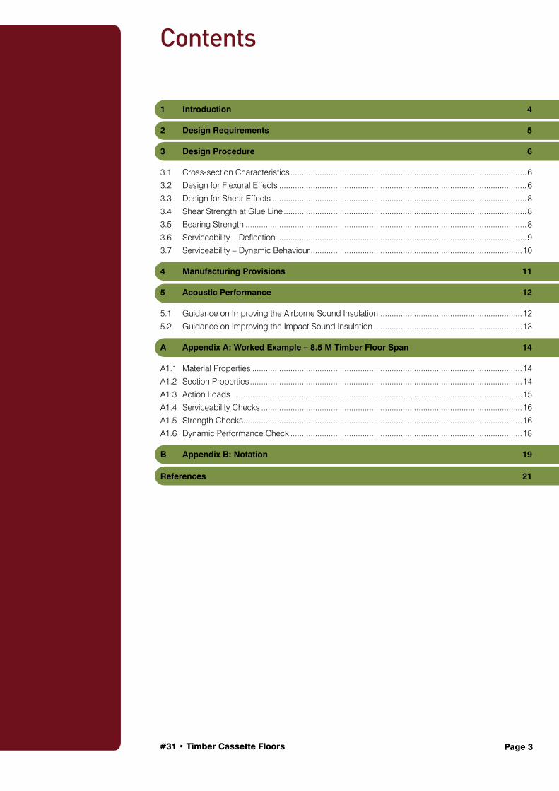
Contents
1 Introduction 4
2 Design Requirements 5
3 Design Procedure 6
3.1 Cross-section Characteristics .........................................................................................................6
3.2 Design for Flexural Effects ..............................................................................................................6
3.3 Design for Shear Effects .................................................................................................................8
3.4 Shear Strength at Glue Line ............................................................................................................8
3.5 Bearing Strength .............................................................................................................................8
3.6 Serviceability – Deflection ...............................................................................................................9
3.7 Serviceability – Dynamic Behaviour ..............................................................................................10
4 Manufacturing Provisions 11
5 Acoustic Performance 12
5.1 Guidance on Improving the Airborne Sound Insulation ................................................................12
5.2 Guidance on Improving the Impact Sound Insulation ..................................................................13
A Appendix A: Worked Example – 8.5 M Timber Floor Span 14
A1.1 Material Properties ........................................................................................................................14
A1.2 Section Properties .........................................................................................................................14
A1.3 Action Loads .................................................................................................................................15
A1.4 Serviceability Checks ....................................................................................................................16
A1.5 Strength Checks ............................................................................................................................16
A1.6 Dynamic Performance Check .......................................................................................................18
B Appendix B: Notation 19
References 21

Page 4#31 • Timber Cassette Floors
This Design Guide complements WoodSolutions Design Guide #30: Timber Concrete Composite Floors. Timber cassette floor systems are well established in Australia, but are mainly used for residential floor loads comprised of either seasoned sawn timber or engineered wood products (EWP) such as I-joists, in conjunction with sawn and dressed timber, particle board or plywood flooring between 17 and 22 mm in thickness.
This Guide presents a design procedure based on AS 1720.1: 2010 Timber structures Part 1: Design methods for composite timber floor structures, manufactured using EWPs such as LVL and glulam and fabricated into ‘T or box beam ‘cassettes’. The notations throughout this document are based on AS 1720.1.
Timber cassette floors consist of a timber joist (LVL or glulam beam) sandwiched between two timber sheathing layers. The sheathing is rigidly connected to the beams by a combination of adhesives and mechanical fasteners to ensure composite action.
Extensive laboratory testing has been undertaken to validate the design assumptions within this Guide. The results of this testing program have confirmed that, provided the flange to web connections meet the prescriptive requirements contained within this Guide, the floor can be designed using the existing provisions of AS 1720.1 as a fully composite section, with linear elastic behaviour in resisting load actions predicted using AS 1170 Structural Design Action series.
The design of timber concrete composite is covered in WoodSolutions Technical Design Guide #30: Timber Concrete Composite Floors for use in commercial and multi-residential timber buildings.
The design of floor diaphragms for wind loading has been described in detail in WoodSolutions Technical Design Guide #35: Floor Diaphragms.
Fire resistance design is not covered in this Design Guide, for further information on fire design, please refer to WoodSolutions Technical Design Guide #15: Fire Design.
Related publications are listed under References at the end of this Guide.
Introduction
1

#31 • Timber Cassette Floors Page 5
Design Requirements
The design procedure addresses performance requirements for the strength (normative) and serviceability (advisory or informative) limit states. Load type and intensity, load combinations and modification factors for both the ultimate and the serviceability limit states have been defined in accordance with the AS 1170 standards.
The limit states that require checking are:
1. Short-term ultimate limit state, where the response of the structure to the maximum load is analysed. It generally corresponds to short-term exertion of the structure.
2. Long-term ultimate limit state, where the analysis focuses on the response of the structure to a quasi-permanent loading and avoiding failure due to creep of the timber member in particular. (Checking the end-of-life ultimate limit states corresponds to analysis and assessment of the durability/reliability of the structure.)
3. Short-term serviceability limit state, which corresponds to the instantaneous response of the structure to an imposed load.
4. Long-term serviceability limit state analysis considers time-dependent variations of the material properties; particularly creep, to identify the service life behaviour.
5. 1.0-kN serviceability limit state: the instantaneous response to and imposed load of 1.0 kN at mid-span provides an indication of dynamic behaviour. This can be replaced with a dynamic analysis if available.
Unless noted otherwise in Figures 2.1 and 2.2, all symbols and letters used in the design procedure conform to those in AS 1720.1.
Figure 2.1: Notation for a typical composite timber floor system.
Figure 2.2: Notation for an individual ‘cassette’ in a typical composite timber floor design procedure.
2
bf.c
h
bf.t
bw
w
h
h
h
h
h
h
c
t
top flange
bottom flange
web
centroid
bf.t
f.t
bf.c
f.c
#31 • Timber Cassette Floors Page 6
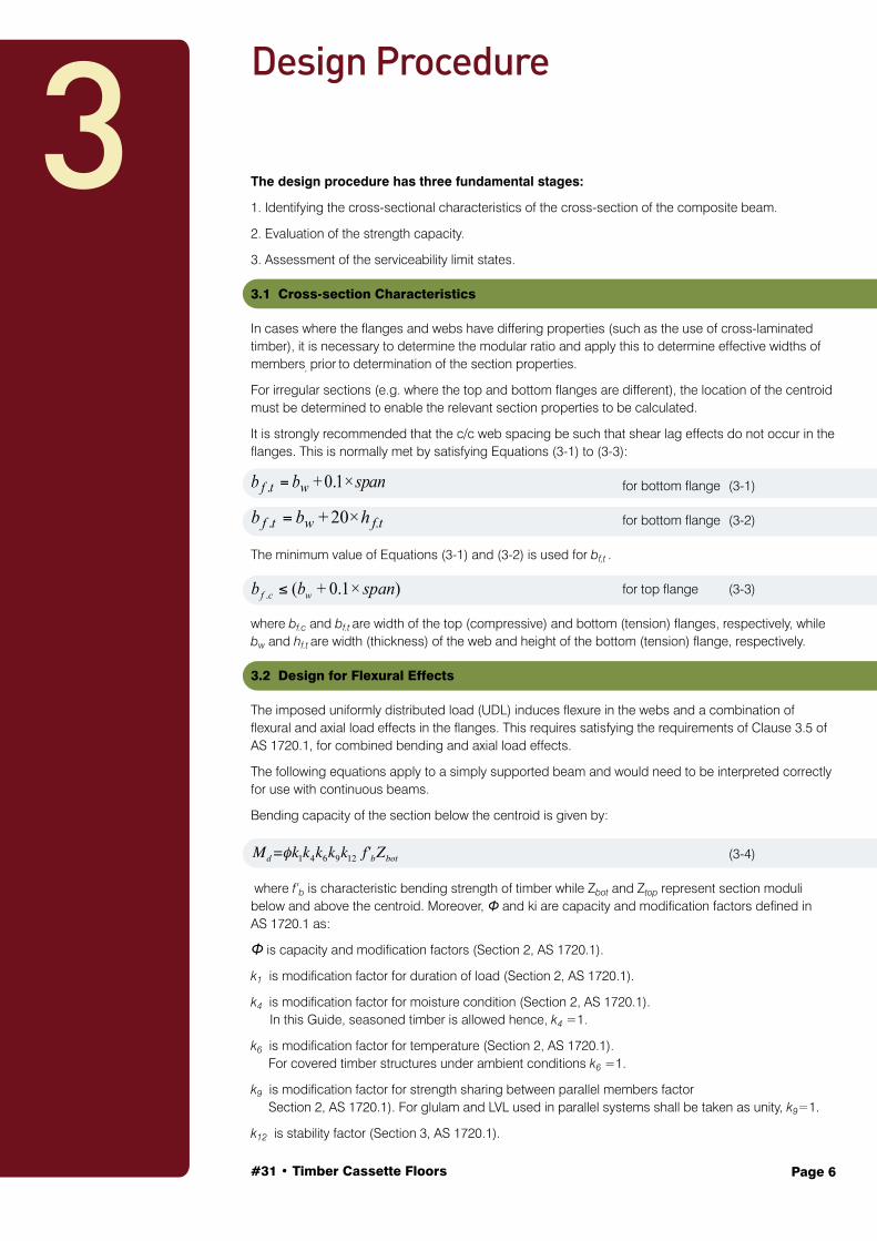
The design procedure has three fundamental stages:
1. Identifying the cross-sectional characteristics of the cross-section of the composite beam.
2. Evaluation of the strength capacity.
3. Assessment of the serviceability limit states.
3.1 Cross-section Characteristics
In cases where the flanges and webs have differing properties (such as the use of cross-laminated timber), it is necessary to determine the modular ratio and apply this to determine effective widths of members, prior to determination of the section properties.
For irregular sections (e.g. where the top and bottom flanges are different), the location of the centroid must be determined to enable the relevant section properties to be calculated.
It is strongly recommended that the c/c web spacing be such that shear lag effects do not occur in the flanges. This is normally met by satisfying Equations (3-1) to (3-3):
for bottom flange (3-1)
for bottom flange (3-2)
The minimum value of Equations (3-1) and (3-2) is used for bf,t .
for top flange (3-3)
where bf.c and bf.t are width of the top (compressive) and bottom (tension) flanges, respectively, while bw and hf.t are width (thickness) of the web and height of the bottom (tension) flange, respectively.
3.2 Design for Flexural Effects
The imposed uniformly distributed load (UDL) induces flexure in the webs and a combination of flexural and axial load effects in the flanges. This requires satisfying the requirements of Clause 3.5 of AS 1720.1, for combined bending and axial load effects.
The following equations apply to a simply supported beam and would need to be interpreted correctly for use with continuous beams.
Bending capacity of the section below the centroid is given by:
(3-4)
where f’b is characteristic bending strength of timber while Zbot and Ztop represent section moduli below and above the centroid. Moreover, Φ and ki are capacity and modification factors defined in AS 1720.1 as:
Φ is capacity and modification factors (Section 2, AS 1720.1).
k1 is modification factor for duration of load (Section 2, AS 1720.1).
k4 is modification factor for moisture condition (Section 2, AS 1720.1). In this Guide, seasoned timber is allowed hence, k4 =1.
k6 is modification factor for temperature (Section 2, AS 1720.1). For covered timber structures under ambient conditions k6 =1.
k9 is modification factor for strength sharing between parallel members factor Section 2, AS 1720.1). For glulam and LVL used in parallel systems shall be taken as unity, k9=1.
k12 is stability factor (Section 3, AS 1720.1).
Design Procedure
3
spanbb wtf
0.1+. =
f.twtf hbb 20+. =
) 0.1+(. spanbb wcf
Md =φk1k4k6k9k12 f'bZbot

#31 • Timber Cassette Floors Page 7
Axial capacity (compression) of the top flange, Nd_top is given by:
(3-5)
Axial capacity (tension) of the bottom flange, Nd_bot is given by:
(3-6)
where f’c and f’t are characteristic axial strength of timber in compression and tension, respectively, while ki and Φ are modification and capacity factors as defined in AS 1720.1. Af.c and Af.t represent cross-sectional areas of the top (compressive) and bottom (tension) flanges, respectively.
The axial force induced in each flange as a result of the bending action is calculated using the following equations:
Axial load induced (compression) in the top flange, N*c is given by:
(3-7)
Axial load induced (tension) in the bottom flange, Nt * is given by:
(3-8)
where hf.c and hf.t are heights of the top (compressive) and bottom (tension) flanges, respectively, while hcentroid and M* represent distance from the centroid to the top of the top flange and bending action due to the factored loads specified in AS1170. I is second moment of inertia of the composite section.
Combined bending and compression – top flange:
(3-9)
(3-10)
Combined bending and tension – bottom flange:
(3-11)
(3-12)
where Z and A are section modulus and section area of the timber module while k12 is AS 1720.1 stability factor used in bending strength calculation. M* and N* are bending and axial actions due to the factored loads specified in AS 1170.
Nd_top =ϕ k1k4k6k12 f'c Af .c
Nd_bot =ϕ k1k4k6k11 f't Af .t
Nc*=
M*(h− hcentroid −hf .c
2)
IAf .c
(M*
Md
)2 + Nc*
Nd _ top
≤1.0
M*
Md
+Nc*
Nd _ top
≤1.0
k12M*
Md
+Nt*
Nd _bot
≤1.0
M*
Md
−Nt*
Nd _bot
Z
A≤1.0
Nt*=
M*(hcentroid −hf .t
2)
IAf .t
φ
φ

#31 • Timber Cassette Floors Page 8
3.3 Design for Shear Effects
Shear is generally not a limiting state for strength in these types of floor beams. However, a check of the web for shear is recommended:
(3-13 )
where f’s and As are characteristic shear strength timber parallel to the grain and area corresponding to shear (As=2/3A) while ki and Φ are modification and capacity factors as defined in AS 1720.1.
Connection details recommended for achieving fully composite design behaviour are specified in Chapter 4. The first moment of shear area (Qtop and Qbot ) and hence the shear flow (qtop and qbot) at the interface between the web and the flanges can be checked using the following equations:
(3-14)
(3-15)
(3-16)
(3-17)
where hc and ht are distances from the centroid to the top of the top flange and the bottom of the bottom flanges, respectively, while (V*) is the acting shear force at the distance of 1.5d from the supports of the LVL modules.
3.4 Shear Strength at Glue Line
In the case of composite timber section, to ensure there is no failure in the glue line at the interfaces of LVL modules, the shear stress at the interfaces between the flange and the web must be checked according to:
(3-18)
V* is the acting shear force at the distance of 1.5d from the supports of the LVL modules and Q is the first moment of area of the LVL cross section at the interface between the flange and the web. d is total depth of the timber cross section. f’s,glue is given by adhesive manufacturers.
3.5 Bearing Strength
The design capacity in bearing must satisfy the condition given in:
(3-19)
(3-20)
where, N*p is the design load in bearing, f’p is the bearing strength of the bottom flange, and Ap is
the bearing area. k7 represents modification factor of length and position of bearing as specified in Section 2 AS 1720.1.
Vd =ϕ k1k4k6 f'S AS
Qtop=Af .c (hc −hf .c
2)
Qbot=Af .t (ht −hf .t
2)
qtop=QtopV
*
I
qbot=QbotV
*
I
QV *
I(2bw )≤Min (f's ), (f's,glue )
ϕN p ≥ NP*
ϕN p =ϕ k1k4k6k7 f'P AP
φ
φ
φ φ
#31 • Timber Cassette Floors Page 9
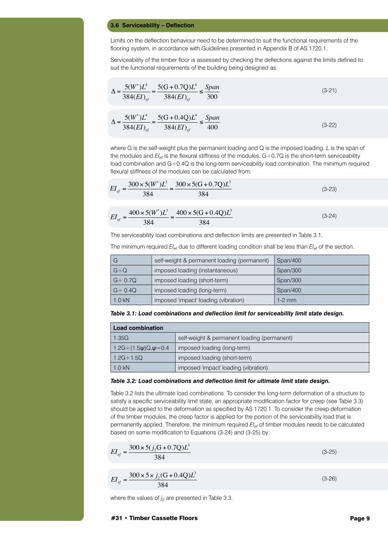
3.6 Serviceability – Deflection
Limits on the deflection behaviour need to be determined to suit the functional requirements of the flooring system, in accordance with Guidelines presented in Appendix B of AS 1720.1.
Serviceability of the timber floor is assessed by checking the deflections against the limits defined to suit the functional requirements of the building being designed as:
(3-21)
(3-22)
where G is the self-weight plus the permanent loading and Q is the imposed loading. L is the span of the modules and EIef is the flexural stiffness of the modules. G+0.7Q is the short-term serviceability load combination and G+0.4Q is the long-term serviceability load combination. The minimum required flexural stiffness of the modules can be calculated from:
(3-23)
(3-24)
The serviceability load combinations and deflection limits are presented in Table 3.1.
The minimum required EIef due to different loading condition shall be less than EIef of the section.
G self-weight & permanent loading (permanent) Span/400
G+Q imposed loading (instantaneous) Span/300
G+ 0.7Q imposed loading (short-term) Span/300
G+ 0.4Q imposed loading (long-term) Span/400
1.0 kN imposed 'impact' loading (vibration) 1-2 mm Table 3.1: Load combinations and deflection limit for serviceability limit state design.
Load combination
1.35G self-weight & permanent loading (permanent)
1.2G+(1.5ψ)Q,ψ=0.4 imposed loading (long-term)
1.2G+1.5Q imposed loading (short-term)
1.0 kN imposed 'impact' loading (vibration) Table 3.2: Load combinations and deflection limit for ultimate limit state design.
Table 3.2 lists the ultimate load combinations. To consider the long-term deformation of a structure to satisfy a specific serviceability limit state, an appropriate modification factor for creep (see Table 3.3) should be applied to the deformation as specified by AS 1720.1. To consider the creep deformation of the timber modules, the creep factor is applied for the portion of the serviceability load that is permanently applied. Therefore, the minimum required EIef of timber modules needs to be calculated based on some modification to Equations (3-24) and (3-25) by:
(3-25)
(3-26)
where the values of j2 are presented in Table 3.3.
Δ =5(W )L4
384(EI )ef
=5(G+ 0.7Q)L4
384(EI )ef
≤Span
300*
*
*Δ =
5(W )L4
384(EI )ef
=5(G+ 0.4Q)L4
384(EI )ef
≤Span
400
EIef =300×5(W )L3
384=
300×5(G+ 0.7Q)L3
384
EIef =400×5(W )L3
384=
400×5(G+ 0.4Q)L3
384
*
EIef =300×5( j2G+ 0.7Q)L
3
384
EIef =300×5× j2 (G+ 0.4Q)L
3
384
#31 • Timber Cassette Floors Page 10
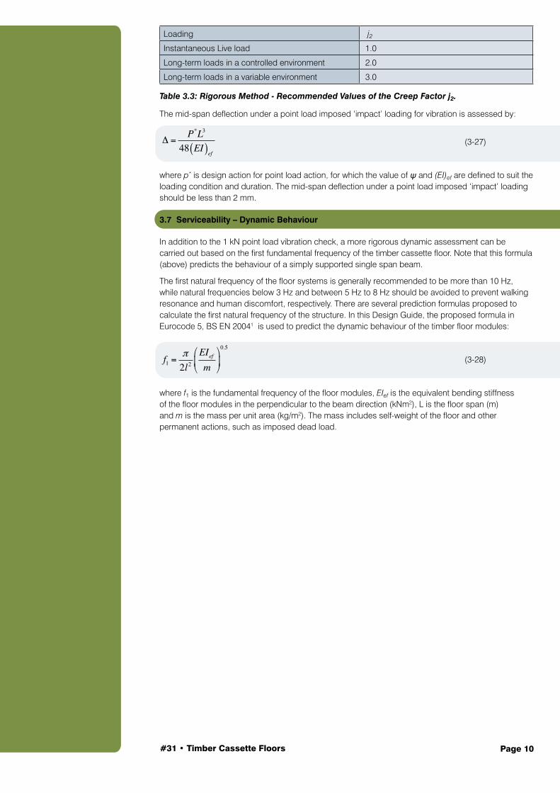
Loading j2
Instantaneous Live load 1.0
Long-term loads in a controlled environment 2.0
Long-term loads in a variable environment 3.0 Table 3.3: Rigorous Method - Recommended Values of the Creep Factor j2.
The mid-span deflection under a point load imposed ‘impact’ loading for vibration is assessed by:
(3-27)
where p* is design action for point load action, for which the value of ψ and (EI)ef are defined to suit the loading condition and duration. The mid-span deflection under a point load imposed ‘impact’ loading should be less than 2 mm.
3.7 Serviceability – Dynamic Behaviour
In addition to the 1 kN point load vibration check, a more rigorous dynamic assessment can be carried out based on the first fundamental frequency of the timber cassette floor. Note that this formula (above) predicts the behaviour of a simply supported single span beam.
The first natural frequency of the floor systems is generally recommended to be more than 10 Hz, while natural frequencies below 3 Hz and between 5 Hz to 8 Hz should be avoided to prevent walking resonance and human discomfort, respectively. There are several prediction formulas proposed to calculate the first natural frequency of the structure. In this Design Guide, the proposed formula in Eurocode 5, BS EN 20041 is used to predict the dynamic behaviour of the timber floor modules:
(3-28)
where f1 is the fundamental frequency of the floor modules, EIef is the equivalent bending stiffness of the floor modules in the perpendicular to the beam direction (kNm2), L is the floor span (m) and m is the mass per unit area (kg/m2). The mass includes self-weight of the floor and other permanent actions, such as imposed dead load.
Δ =P*L3
48 EI( )ef
f1 =π2l2
EIef
m
⎛
⎝⎜
⎞
⎠⎟
0.5

#31 • Timber Cassette Floors Page 11
The recommended procedure for connecting flanges to webs is ‘gluing and screwing’. The design philosophy is that the glue creates an infinitely stiff bond to resist serviceability load events, while the screws provide a mechanical connection so composite action occurs at the design ultimate load events.
In research by the University of Technology Sydney for the Structural Timber Innovation Company, the glue bond was a PURBOND polyurethane glue, fastened using 14G Type 17 screws (see Figure 4.1) at nominal centres of 400 mm c/c along the entire length of the web. It is recommended this method be a starting point for design. Reference should always be made to timber fabricators for their preferred ‘gluing and screwing’ method.
Figure 4.1: Dimensions of the Type 17 screws used for manufacture.
4Manufacturing Provisions

#31 • Timber Cassette Floors Page 12
From a review of existing knowledge on acoustic performance of timber floors, it is clear that both airborne and impact sound insulation requirements can be fulfilled by applying suitable treatments and proper detailing to timber floors. It is important to understand the difference in the factors affecting the airborne and impact sound insulation to address the acoustic performance of a floor.
A number of best practice guidelines based on existing knowledge on acoustic performance of timber floors are summarised below:
Figure 5.1: Double layer floor with good acoustic properties.
5.1 Guidance on Improving the Airborne Sound Insulation
1. Larger spacing and separated layers of double layer floor: The ceiling boards should not be directly connected to the floor joists. Ceiling should be separated from the floor joists (distance a in Figure 5.1) by providing either resilient support for the ceiling board or separate joists for ceiling boards supported on the walls.
2. The ceiling boards should have a minimum density of 10 kg/m2. Although single layer ceiling boards provide adequate airborne sound insulation, it is preferable to use two ceiling boards with staggered joints for better sound insulation performance.
3. The floor cavity between the subfloor and ceiling should be filled with sound absorbing material (mineral fibre). The material’s type and density is dependent on the floor’s construction. The BCA may require the mineral wool to be non-combustible.
4. Increasing the mass of the joist may not improve the airborne sound insulation of timber floors. The thickness of sound absorbing material, arrangement of resilient channels and depth and spacing of joist has some effect on the airborne sound insulation behaviour, but it is not as significant as the effect of having ceiling boards separated from the joists.
5. A combination of sub-floor with a mass of 20 kg/m2 and 150 mm thick sound absorbing material with ceiling boards supported on resilient metal channels has been reported to give good airborne sound insulation for timber floors.
6. Thin, heavyweight, and non-rigid layers, or asymmetric construction (d1/d2 = about 2 in Figure 5.1) options, are suitable for satisfactory acoustic properties.2
5Acoustic Performance

#31 • Timber Cassette Floors Page 13
5.2 Guidance on Improving the Impact Sound Insulation
1. Increasing the mass or separating the ceiling from the floor joists can improve impact sound insulation of timber floors.
2. Good impact sound insulation can be achieved for floors constructed with a sub-floor layer (e.g. particleboard, gypsum board), separated ceiling using resilient channels and sound absorbing material in the floor cavity. The requirements for the density of floor boards and insulation material are same as that for airborne sound insulation.
3. A floor with a mass of at least 200 kg/m3 has been reported to have adequate impact sound insulation. However, mass alone may not be sufficient and attention also needs to be given to the floor finish and ceiling treatment.
4. Providing soft floor topping can reduce high frequency impact sound transmission. Hard floor toppings such as concrete, marble, tile and hardwood lead to problems with high frequency impact noise. If a hard floor topping is unavoidable, a floating floor on a resilient layer should be used.
5. A top floor layer should be installed with a resilient under layer and should not be screwed directly to the timber joist (Figure 5.2) or in direct connection with walls or columns. Place a resilient under layer between the floor covering and any walls or columns.
6. The addition of transverse stiffeners can improve the high frequency impact insulation of the floor but reducing the joist spacing may not always improve this.
Figure 5.2: Acoustic improvement methods.

Page 14#31 • Timber Cassette Floors
In this section, the serviceability and ultimate capacities of a timber cassette floor are calculated in accordance with this Guide. As shown in Figure A1.1, LVL 11 was used for the timber cassette floor. The different stages of calculations are summarised in the following sections.
Figure A1.1: Dimensions of 8.5 m timber modules.
A1.1 Material Properties
Material Properties of the timber module based on manufacturer’s data are:
• Timber type LVL 11
• Timber modulus Et = 11000 MPa
• Timber density ρ = 620 kg/m3
• Timber bending strength f’b = 38 MPa
• Timber compression strength f’c = 38 MPa
• Timber tensile strength f’t = 26 MPa
• Timber shear strength f’s = 5.3 MPa
A1.2 Section Properties
for bottom flange
bf.t = minimum of (35+0.1 x 8500) and (35+20 x 63) = 885 mm (width of the bottom flange)
bw = 35 mm (thickness of the web)
hf.t = 63 mm (height of the bottom flange)
bf.c ≤ ( bw+0.1 x span) for top flange
bf.c = 35+0.1 x 8500 = 885 mm (width of the top flange)
Neutral axis (from bottom to centroid):
yc = 147.85 mm
Ac = 37175 mm2
At = 61635 mm2
The calculation of moment of inertia of the timber floor section is given in Table A1.1. The equivalent section of timber floor is used for the calculation as shown in Figure A1.2.
AAppendix A: Worked Example – 8.5 m Timber Floor Span
f.tw
wtf hb
spanbb
20+ 0.1+
Min.
#31 • Timber Cassette Floors Page 15
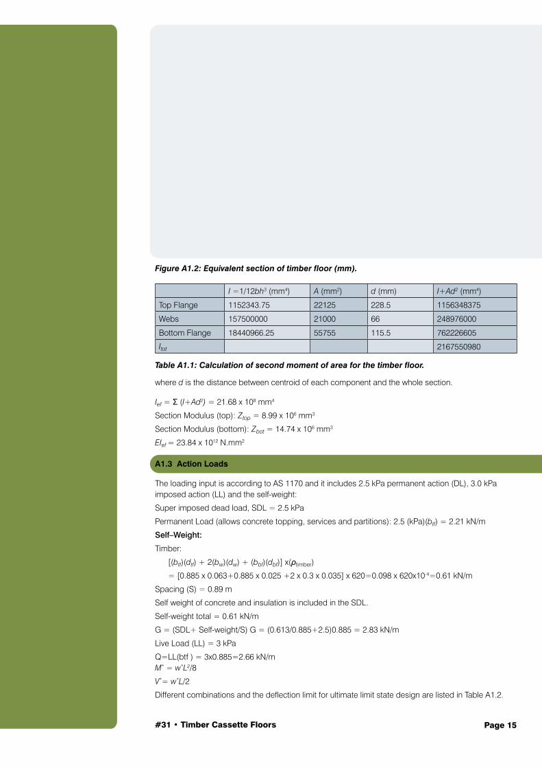
Figure A1.2: Equivalent section of timber floor (mm).
I =1/12bh3 (mm4) A (mm2) d (mm) I+Ad2 (mm4)
Top Flange 1152343.75 22125 228.5 1156348375
Webs 157500000 21000 66 248976000
Bottom Flange 18440966.25 55755 115.5 762226605
Itot 2167550980 Table A1.1: Calculation of second moment of area for the timber floor.
where d is the distance between centroid of each component and the whole section.
Ief = Σ (I+Ad2) = 21.68 x 108 mm4
Section Modulus (top): Ztop = 8.99 x 106 mm3
Section Modulus (bottom): Zbot = 14.74 x 106 mm3
EIef = 23.84 x 10¹² N.mm2
A1.3 Action Loads
The loading input is according to AS 1170 and it includes 2.5 kPa permanent action (DL), 3.0 kPa imposed action (LL) and the self-weight:
Super imposed dead load, SDL = 2.5 kPa
Permanent Load (allows concrete topping, services and partitions): 2.5 (kPa)(btf) = 2.21 kN/m
Self–Weight:
Timber:
[(btf)(dtf) + 2(bw)(dw) + (bbf)(dbf)] x(ρtimber)
= [0.885 x 0.063+0.885 x 0.025 +2 x 0.3 x 0.035] x 620=0.098 x 620x10-4=0.61 kN/m
Spacing (S) = 0.89 m
Self weight of concrete and insulation is included in the SDL.
Self-weight total = 0.61 kN/m
G = (SDL+ Self-weight/S) G = (0.613/0.885+2.5)0.885 = 2.83 kN/m
Live Load (LL) = 3 kPa
Q=LL(btf ) = 3x0.885=2.66 kN/m M* = w*L2/8
V*= w*L/2
Different combinations and the deflection limit for ultimate limit state design are listed in Table A1.2.

#31 • Timber Cassette Floors Page 16
A1.4 Serviceability Checks
The load combinations and the deflection criteria for serviceability check are presented in this Guide.
According to AS 1170 and AS 1720.1, Equations (3-22) and (3-23) must be satisfied to check the serviceability performance of timber modules.
Since the moisture of content of timber module (LVL) is less than 15%, the creep factor, j2 is equal to 1 and 2 for short-term and long-term serviceability check, respectively (Table 0.3).
To consider the creep deformation of the timber modules, the creep factor is applied for the portion of the serviceability load that is permanently applied. Hence, the minimum required short- and long-term EIeff of timber modules need to be calculated based on Equations (3-24) and (3-25), respectively:
short-term EIef (Equation [3-24])
short-term EIef (Equation [3-25])
Comparing minimum required EIef (obtained from Equations (3-24) and (3-25) and EIef of the section (23.8x10⁻¹³ Nmm2), the specified section satisfied the minimum EIef requirement.
Considering the effect of creep factor, the short- and long-term deflections of the 8.5 m LVL modules (Equations [3-24] and [3-25]) are equal to 13.4 mm and 11.1 mm, respectively, which are less than Span/300 (or 28.3 mm) and Span/400 (or 21.3 mm), respectively.
13.4 < 28.3 mm OK
11.1 < 21.3 mm OK
Now consider the short-term deflection check for 1 kN point load – Equation (3-28).
0.54 < 2 mm OK Short-term deflection check for 1 kN point load) is also equal to 0.54 mm which is smaller than the deflection limit (2 mm).
A1.5 Strength Checks
Characteristic values for structural LVL shall be obtained from the manufacturer. Characteristic values for LVL shall include consideration of the section sizes to which they are intended to apply. Unless otherwise specified by the manufacturer, the characteristic values for LVL for bending and tension shall be modified using Equations specified in Section 8.3 AS 1720.1.
Table A1.2 shows the load combination and the maximum bending and shear force (refer Table 0.2 in body of text). The required modification factors are presented in Table A1.3 and Table A1.4 which are based on AS 1720.1.
Combination w* (kNm) M* (kNm) V* (kN) N*c (kN) N*t (kN)
1.35G 3.8 34.5 16.2 80.5 185.9
1.2G + (1.5ψ)Q, ψ=0.4 5.0 45.1 21.1 105.1 242
1.2G + 1.5Q 7.4 66.7 31.4 155.5 359.4 Table A1.2: Load combinations and deflection limit for ultimate limit state design.
EIef =300×5( j2G+ 0.7Q)L
3
384=1.13×10¹³Nmm2
EIef =300×5× j2 (G+ 0.4Q)L
3
384=1.87×10¹³Nmm2
Δ =5(W*)L4
384(EIef )=5(G+ 0.7Q)L4
384(EIef )=5(2.83+ 0.7×2.66)85004
384(23.8×10¹² )≤
Span
300
Δ =5(W*)L4
384(EI )ef
=5(G + 0.4Q)L4
384(EI )ef
=5(2.83+ 0.4×2.66)85004
384(23.8×10¹² )≤
Span
400
Δ =PL3
48(EI )ef
=1×85003
48×1.06×1013 ≤ 2 mm
#31 • Timber Cassette Floors Page 17
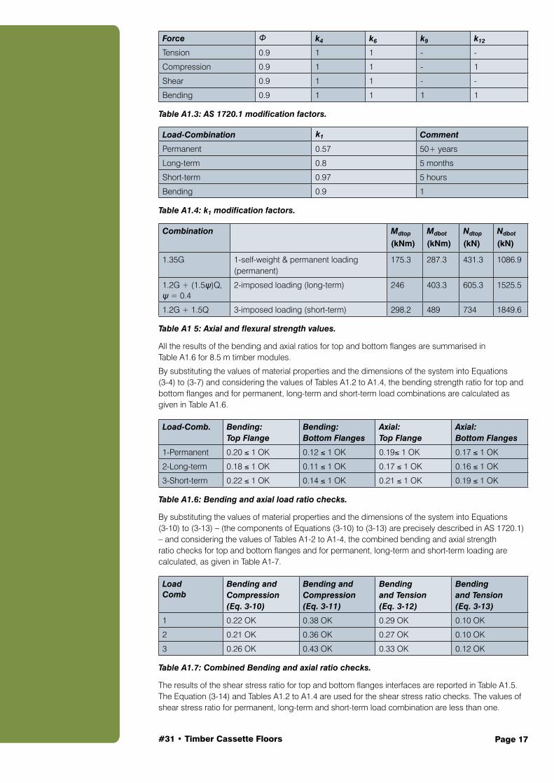
Force Φ k4 k6 k9 k12
Tension 0.9 1 1 - -
Compression 0.9 1 1 - 1
Shear 0.9 1 1 - -
Bending 0.9 1 1 1 1 Table A1.3: AS 1720.1 modification factors.
Load-Combination k1 Comment
Permanent 0.57 50+ years
Long-term 0.8 5 months
Short-term 0.97 5 hours
Bending 0.9 1 Table A1.4: k1 modification factors.
Combination Mdtop
(kNm)Mdbot
(kNm)Ndtop
(kN)Ndbot
(kN)
1.35G 1-self-weight & permanent loading (permanent)
175.3 287.3 431.3 1086.9
1.2G + (1.5ψ)Q, ψ = 0.4
2-imposed loading (long-term) 246 403.3 605.3 1525.5
1.2G + 1.5Q 3-imposed loading (short-term) 298.2 489 734 1849.6 Table A1 5: Axial and flexural strength values.
All the results of the bending and axial ratios for top and bottom flanges are summarised in Table A1.6 for 8.5 m timber modules.
By substituting the values of material properties and the dimensions of the system into Equations (3-4) to (3-7) and considering the values of Tables A1.2 to A1.4, the bending strength ratio for top and bottom flanges and for permanent, long-term and short-term load combinations are calculated as given in Table A1.6.
Load-Comb. Bending: Top Flange
Bending: Bottom Flanges
Axial: Top Flange
Axial: Bottom Flanges
1-Permanent 0.20 ≤ 1 OK 0.12 ≤ 1 OK 0.19≤ 1 OK 0.17 ≤ 1 OK
2-Long-term 0.18 ≤ 1 OK 0.11 ≤ 1 OK 0.17 ≤ 1 OK 0.16 ≤ 1 OK
3-Short-term 0.22 ≤ 1 OK 0.14 ≤ 1 OK 0.21 ≤ 1 OK 0.19 ≤ 1 OK Table A1.6: Bending and axial load ratio checks.
By substituting the values of material properties and the dimensions of the system into Equations (3-10) to (3-13) – (the components of Equations (3-10) to (3-13) are precisely described in AS 1720.1) – and considering the values of Tables A1-2 to A1-4, the combined bending and axial strength ratio checks for top and bottom flanges and for permanent, long-term and short-term loading are calculated, as given in Table A1-7.
LoadComb
Bending and Compression (Eq. 3-10)
Bending and Compression (Eq. 3-11)
Bending and Tension (Eq. 3-12)
Bending and Tension (Eq. 3-13)
1 0.22 OK 0.38 OK 0.29 OK 0.10 OK
2 0.21 OK 0.36 OK 0.27 OK 0.10 OK
3 0.26 OK 0.43 OK 0.33 OK 0.12 OK Table A1.7: Combined Bending and axial ratio checks.
The results of the shear stress ratio for top and bottom flanges interfaces are reported in Table A1.5. The Equation (3-14) and Tables A1.2 to A1.4 are used for the shear stress ratio checks. The values of shear stress ratio for permanent, long-term and short-term load combination are less than one.

#31 • Timber Cassette Floors Page 18
Load-Combination Vd (kN) Max Flexural Shear
Permanent 179.1 0.09 ≤1 OK
Long-term 251.3 0.08 ≤1 OK
Short-term 304.7 0.10 ≤1 OK Table A1.8: Shear stress ratio check.
A1.6 Dynamic Performance Check
For the dynamic performance of the LVL modules, the first natural frequency of the system is calculated according to Equation (3-29):
The first natural frequency of the system is about 4.33 Hz which is in the safe frequency zone.
f1 =π
2l2
EIef
m
⎛
⎝⎜
⎞
⎠⎟
0.5
=π
2(8.5)210603.25
0.267⎛
⎝⎜
⎞
⎠⎟= 4.33 Hz

#31 • Timber Cassette Floors Page 19
Symbols and letters used in the Guide are listed below:
A cross-sectional area of the entire section
Af.c cross-sectional area of the top (compressive) flange
Af.t cross-sectional area of the bottom (tension) flange
As shear area of the web = 2/3 bw hw
Aw cross-sectional area of the web
Ap bearing area
bf.t width of the bottom (tension) flange
bw width (thickness) of the web
d total depth of the timber cross section
h overall depth of floor
hc distance from the centroid to the top of the top flange
ht distance from the centroid to the bottom of the bottom flange
hw depth of the web
hf.t height of the bottom (tension) flange
hcentroid distance from the bottom of the bottom flange to the centroid = h f.t
I second moment of inertia of the composite section
Z top section modulus above the centroid (top flange)
Z bot section modulus below the centroid (bottom flange)
E value of the modulus of elasticity of the timber members
f1 fundamental frequency of the floor modules
characteristic strength in bending
characteristic strength in compression
characteristic strength in shear
f’s,glue characteristic shear strength of the adhesive
characteristic strength in tension
j2 stiffness modification factor – load duration specified in AS 1720.1
k1 duration of load (timber) specified in AS 1720.1
k4 moisture condition (timber) specified in AS 1720.1
k6 temperature (timber) specified in AS 1720.1
k7 length and position of bearing (timber) specified in AS 1720.1
k9 strength sharing between parallel members specified in AS 1720.1
BAppendix B: Notation
fb'
fc'
fs'
ft'
#31 • Timber Cassette Floors Page 20
k11 size factor (timber) – this is normally applied to the characteristic strength
property by the manufacturer
k12 stability factor (timber) specified in AS 1720.1
m mass per unit area
M* moment action resulting from applied loads
M d_top design moment capacity – top flange
M d_bot design moment capacity – bottom flange
N*c axial force (compression) induced in top flange from bending
N*t axial force (tension) induced in bottom flange from bending
N d_top design axial capacity (compression) – top flange
N d_bot design axial capacity (tension) – bottom flange
Q top first moment of shear area for top flange
Q bot first moment of shear area for bottom flange
q top shear flow at interface between web and top flange
q bot shear flow at interface between web and bottom flange
V* maximum shear effect
Vd design shear capacity of the web
Φ capacity factor

#31 • Timber Cassette Floors Page 21
1. BS EN 2004, Eurocode 5-Design of Timber Structures-Part 1-1 in General rules and rules for buildings. 2004, European Committee for Standardization: Brussels, Belgium.
2. Kolb, J., Systems in Timber Engineering: Loadbearing Structures and Component Layers. 2008: Springer.
Australian Standards
AS 1170.1, Structural design actions, in Part 1: Permanent, imposed and other actions. Standards Australia, 2002.
AS 1720.1, Timber structures, in Part 1: Design methods. Standards Australia, 2010.
WoodSolutions Technical Design Guides
WoodSolutions Technical Design Guide #15: Fire Design, Forest and Wood Products Australia, Melbourne, Australia, 2016.
WoodSolutions Technical Design Guide #30: Timber Concrete Composite Floors. Forest and Wood Products Australia, Melbourne, Australia, 2016.
WoodSolutions Technical Design Guide #35: Floor Diaphragm. Forest and Wood Products Australia, Melbourne, Australia, 2016.
References

Discover more ways to build your knowledge of wood If you need technical information or inspiration on designing and building with wood, you’ll find WoodSolutions has the answers. From technical design and engineering advice to inspiring projects and CPD linked activities, WoodSolutions has a wide range of resources and professional seminars.
www.woodsolutions.com.auYour central resource for news about all WoodSolutions activities and access to more than three thousand pages of online information and downloadable publications.
Technical PublicationsA suite of informative, technical and training guides and handbooks that support the use of wood in residential and commercial buildings.
WoodSolutions TutorialsA range of practical and inspirational topics to educate and inform design and construction professionals. These free, CPD related, presentations can be delivered at your workplace at a time that suits you.
Seminars and EventsFrom one day seminars featuring presentations from leading international and Australian speakers to international tours of landmark wood projects, WoodSolutions offer a range of professional development activities.
What is WoodSolutions?Developed by the Australian forest and wood products industry for design and building professionals, WoodSolutions is a non-proprietary source of information from industry bodies, manufacturers and suppliers.