woodco usa equipment catalog · pdf filep.o. box 1261 houston, texas 77251-1261 ... 2.8 test...
TRANSCRIPT

Effective Date: January. 1, 2010 Terms of Use and Copyright © 2017 WOODCO USA
CATALOG FOR WOODCO USA® Brand PRESSURE CONTROL EQUIPMENT
API flanges, double studded adapters, API hubs, flanged and studded drilling spools, spacer spools, adapter spools, studded crosses and tees, flange x union adapters, manifold equipment, wellhead equipment, and drill through equipment; many items of equipment made as one piece without fabrication or assembly welding (no welding). Flange and Hub Identification Worksheets, and copies of WOODCO USA API 6A, 16A, and 17D License Certificates, also included.
TRADEMARK
REG. U.S. PATENT OFFICE
WOODCO USAP.O. Box 1261
Houston, Texas 77251-1261Phone: 713-672-9491
U.S. and Canada: 1-800-496-6326Fax: 713-672-8768
www.woodcousa.comEmail: [email protected]
MANUFACTURER
WOODCO USA presents this catalog to gain your attention and secure your business
USA
WOODCO ®
BUY THE BRAND
© W
OODC
O US
A
Page 2Phone: 713-672-9491
TABLE OF CONTENTS
www.woodcousa.com Terms of Use and Copyright © 2017 WOODCO USA
Section 1.0 General . . . . . . . . . . . . . . . . . . . . . . . . . . . . . . . . . . . . . . . . . . . . . . . . . . . . . . . . . . . . . 3 1.1 Purpose . . . . . . . . . . . . . . . . . . . . . . . . . . . . . . . . . . . . . . . . . . . . . . . . . . . . . . . . . . . . . 3 1.2 Products . . . . . . . . . . . . . . . . . . . . . . . . . . . . . . . . . . . . . . . . . . . . . . . . . . . . . . . . . . 4 1.3 Application . . . . . . . . . . . . . . . . . . . . . . . . . . . . . . . . . . . . . . . . . . . . . . . . . . . . . . . 4 1.4 Reference Standards . . . . . . . . . . . . . . . . . . . . . . . . . . . . . . . . . . . . . . . . . . . . . 4 1.5 Material . . . . . . . . . . . . . . . . . . . . . . . . . . . . . . . . . . . . . . . . . . . . . . . . . . . . . . . 4 1.6 Quality . . . . . . . . . . . . . . . . . . . . . . . . . . . . . . . . . . . . . . . . . . . . . . . . . . . . . . . . . 5 1.7 Standardization . . . . . . . . . . . . . . . . . . . . . . . . . . . . . . . . . . . . . . . . . . . . . . . . . . . 5Section 2.0 Equipment . . . . . . . . . . . . . . . . . . . . . . . . . . . . . . . . . . . . . . . . . . . . . . . . . 5 2.1 Flanges and Hubs (Loose Connectors) . . . . . . . . . . . . . . . . . . . . . . . . . . . . . . . . 5 2.2 Flanges, Adapter * . . . . . . . . . . . . . . . . . . . . . . . . . . . . . . . . . . . . . . . . . . . . . . . . . . 7 2.3 Spools, Adapter . . . . . . . . . . . . . . . . . . . . . . . . . . . . . . . . . . . . . . . . . . . . . . . . . . . 8 2.4 Spools, Drilling and Diverter . . . . . . . . . . . . . . . . . . . . . . . . . . . . . . . . . . . . . . . . . 9 2.5 Spools, Spacer (Spools, Riser) . . . . . . . . . . . . . . . . . . . . . . . . . . . . . . . . . . . . 11 2.6 Crosses and Tees . . . . . . . . . . . . . . . . . . . . . . . . . . . . . . . . . . . . . . . . . . . . . . . . . . 12 2.6.1 Crosses and Tees, Studded . . . . . . . . . . . . . . . . . . . . . . . . . . . . . . . . . . . . . 12 2.6.2 Crosses and Tees, Flange . . . . . . . . . . . . . . . . . . . . . . . . . . . . . . . . . . . . . . . 13 2.6.3 Crosses and Tees, Hub . . . . . . . . . . . . . . . . . . . . . . . . . . . . . . . . . . . . . . . . . 14 2.7 Choke Manifold Equipment . . . . . . . . . . . . . . . . . . . . . . . . . . . . . . . . . . . . . . . . . . . . . . . 14 2.8 Test Rack Flanges and BOP Test Stumps . . . . . . . . . . . . . . . . . . . . . . . . . . . . . . . . . . . . . 17Section 3.0 Equipment Made Without Assembly Welding . . . . . . . . . . . . . . . . . . . . . . . . . . . . 18 3.1 Flanges, Adapter (made without assembly welding) * . . . . . . . . . . . . . . . . . . . . . . 19 3.2 Spools, Adapter (made without assembly welding) . . . . . . . . . . . . . . . . . . . . . . . 20 3.3 Spools, Drilling (made without assembly welding) . . . . . . . . . . . . . . . . . . . . . . . . 21 3.4 Spools, Spacer (Riser Spools made without assembly welding) . . . . . . . . . . . . . . . . 22 3.5 Crosses and Tees (made without assembly welding) . . . . . . . . . . . . . . . . . . . . . . 23 3.6 Choke Manifold Equipment (made without assembly welding) . . . . . . . . . . . . . . . . . . . 24 3.7 Special Purpose Equipment (made without assembly welding) . . . . . . . . . . . . . . . . . . . 24 Section 4.0 Worksheets . . . . . . . . . . . . . . . . . . . . . . . . . . . . . . . . . . . . . . . . . . . . . . . 26 4.1 Flange Identification Worksheet . . . . . . . . . . . . . . . . . . . . . . . . . . . . . . . . . . 26 4.2 Hub Identification Worksheet . . . . . . . . . . . . . . . . . . . . . . . . . . . . . . . . . . 27Appendix A, Guide to Order Placement . . . . . . . . . . . . . . . . . . . . . . . . . . . . . . . . . . . . . . . . . . 28 Appendix A, Continued, Order Placement Worksheet . . . . . . . . . . . . . . . . . . . . . . . . . . . . . 32 Appendix B, API Monogram, Why . . . . . . . . . . . . . . . . . . . . . . . . . . . . . . . . . . . . . . 33 Appendix C, API 6A, Certificate of Authority to Use Official Monogram . . . . . . . . . . . . . . 34 Appendix D, API 16A, Certificate of Authority to Use Official Monogram . . . . . . . . . . . . . 35Appendix E, API 17D, Certificate of Authority to Use Official Monogram . . . . . . . . . . . . . 36* API Top Connectors, see Supplement 1 to this catalog.
WOODCO USA presents this catalog to secure your business.Catalog for WOODCO USA® Brand Pressure Control Equipment
© W
OODC
O US
A

www.woodcousa.com Terms of Use and Copyright © 2017 WOODCO USA
WOODCO USA presents this catalog to secure your business.Catalog for WOODCO USA® Brand Pressure Control Equipment Page 3
Phone: 713-672-9491
1.0 General This catalog provides information about the variety of pressure control fittings available from WOODCO USA. It presents equipment by names commonly used and provides illustrations for use as a reference to improve communications and avoid errors.
WOODCO USA manufactures products in accordance with API and/or national or international standards. The following figures illustrate unusual designs not specifically mentioned in the various sections of this catalog or API Specifications, but which otherwise meet design requirements. A surprising number of unusual configurations which conform to API specification requirements can bear the API Monogram.
1.1 PurposeWOODCO USA wants this catalog to communicate in a manner that will properly and usefully inform buyers and users of pressure control equipment that WOODCO USA offers high quality, safe, interchangeable equipment that will contribute to their success. WOODCO USA wants to sell these products.
Figure 1.1 A
FLANGE X WELD NECKTEE
FLANGE ENDCONNECTION
FLANGEOUTLETCONNECTION
MEETS DESIGN CRITERIA OF API 6A, MAY BEAR THE API MONOGRAM AFTER HYDROSTATIC TESTING.
WELD NECKCONNECTION
Figure 1.1 B
FLANGE X HUB OUTLETTEE
FLANGE ENDCONNECTION
MEETS DESIGN CRITERIA OF API 6A. THIS PRODUCT MAY BEAR THE API MONOGRAM.
FLANGE ENDCONNECTION
FLANGES WITH WELD NECKS THAT CONFORM TO API SPECIFICATIONS MAY BEAR THE API MONOGRAM. (BUYERS MAY SPECIFY OTHER WELDNECK DIMENSIONS)
Figure 1.1 C
WELD NECK FLANGE
Figure 1.1 D
MEETS DESIGN CRITERIA OF API 6A. THIS PRODUCT MAY BEAR THE API MONOGRAM
STUDDEDOUTLETCONNECTION
FLANGE X HUBTEE
HUB ENDCONNECTION
FLANGE ENDCONNECTION
WO
OD
CO
USA
C
WOODCO U
SA
C
WOODCO USA
C
WO
OD
CO
USA
C
© W
OODC
O US
A

www.woodcousa.com Terms of Use and Copyright © 2017 WOODCO USA
Page 4Phone: 713-672-9491
1.2 Products WOODCO USA provides the following standard products in all sizes and pressure ratings and meeting one or more specifications listed in section 1.4 of this catalog. Additionally, WOODCO USA can design and manufacture, or manufacture from the Buyers’ designs, specified products consistent with criteria designated in standards listed in section 1.4., e.g. tubing, bends, and other items to satisfy customer service needs and certifying authority requirements. Also see section 1.0 of this catalog.
Loose Connectors Flanges: Blind
TargetTestInstrumentThreadedWeld Neck
Adapter Flanges Double Studded Single Studded Hubs: Blind Target Test Threaded Weld NeckSpools, Adapter Flange X Flange Flange X Studded Flange X Hub Flange X Union Hub X Hub Hub X Union Lubricator AdapterSpools, Drilling Flange Studded Hub Spools, Spacer Flange Hub
Crosses and Tees Studded Flange Hub Manifold Equipment Weld Neck: Crosses, Tees, and Elbows Flange X Weld Neck Fittings Transmitter Flange Transmitter Manifold Buffer Manifold For equipment Made Without Assembly Welding see Section 3.0
1.3 Application WOODCO USA equipment described in this catalog meets appropriate API and other national and/or international standards for:
Wellhead Equipment Drill Through Equipment Manifold Systems
1.4 Reference Standards API SPEC 6A, Wellhead and Christmas Tree Equipment. API SPEC 16A, Drill Through Equipment. ANSI B16.5, Pipe Flanges and Flange Fittings. ANSI B31.3, Chemical Plant and Petroleum Refinery Piping. ASME B & PV CODE, SECT VIII, DIV 1 AND DIV 2, Rules For Construction of Pressure Vessels. ASME B & PV CODE, SECT IX, Welding and Brazing Qualifications. MSS SP-44, Steel Pipe Line Flange Specifications NACE MRO175 / ISO 15156, Standard Material Requirements.
1.5 Material WOODCO USA has material specifications which meet or exceed the requirements of API and/or other national or international standards.
WOODCO USA presents this catalog to secure your business.Catalog for WOODCO USA® Brand Pressure Control Equipment
© W
OODC
O US
A

www.woodcousa.com Terms of Use and Copyright © 2017 WOODCO USA
Page 5Phone: 713-672-9491
1.6 Quality WOODCO USA defines “Product Quality” as conformance to specified requirements. Approved Vendors provide material, products, and services which conform to WOODCO USA and national and/or international standards. Receiving Inspection screens all incoming material before processing. Additional inspections during manufacturing and after final operations assure compliance with applicable standards. Buyers may request supplemental inspections required to meet special needs. 1.7 StandardizationWOODCO USA manufactures all products in compliance with applicable national and/or international standards. However, many standards, including API Specifications, allow options and do not define aspects of clearance. The following list provides a sampling of items of standardization adopted by WOODCO USA:
Flange thickness tolerance allows stock for recutting ring grooves. Optional corrosion resistant ring grooves’ inlay depth allows stock for recutting ring grooves. Steel chemistry facilitates later weld repair. Raised faces omitted on studded flanges facilitates interchangeability of tap end studs. Studded flange faces equipped with tap end (double end) studs. WOODCO USA design criteria assures nut and wrench clearances.
2.0 Equipment 2.1 Flanges and Hubs (Loose Connectors) WOODCO USA manufactures API Spec 6A Flanges and other Loose Connectors in all sizes and pressure ratings; and in all the common configurations as follows:
Blind (with or without counterbore)Target (lead filled)Test (tapped through center or side)Instrument (through bolt spacer)Threaded (API tubing, casing, line pipe, or special)Weld Neck (API weld neck or customer specified weld neck)Transmitter (multiple tapped, see Section 2.7)Adapter (see Section 2.2)
Loose Connectors manufactured as Clamp Hubs shall conform to API Spec 16A. See WOODCO USA CATALOG FOR CLAMPS for information about clamps.
Hub connection equipment with API 6A monogram shall meet PSL 2 minimum requirements per API Spec 6A. Refer to the following figures for examples of Loose Connector configurations:
Figure 2.1 A
Figure 2.1 B
WOODCO USA presents this catalog to secure your business.Catalog for WOODCO USA® Brand Pressure Control Equipment
OALMIN.
6B BLIND FLANGE *
*6B FLANGES HAVE R RING GROOVES(see tables in API SPEC. 6A)
WOODCO USA
C
OALMIN.
6BX BLIND FLANGE **
**6BX FLANGES HAVE BX RING GROOVES(see tables in API SPEC. 6A)
OAL = T + J3 OR J4, MINIMUM AS SPECIFIED IN API SPECIFICATION 6A.
WOODCO USA
C
© W
OODC
O US
A

www.woodcousa.com Terms of Use and Copyright © 2017 WOODCO USA
Page 6Phone: 713-672-9491
Figure 2.1 I
WELD NECK FLANGE
Figure 2.1 J
16B OR 16BX BLIND HUB *
To identify Hubs or to determine which Clamps fit which specific Hubs see: 4.2 Hub Identification Worksheet.
* 16B HUBS HAVE SR RING GROOVES,16BX HUBS HAVE BX RING GROOVES.
(see tables in API SPEC. 16A)
Figure 2.1 C
6BX BLIND FLANGE WITH COUNTERBORE
Figure 2.1 D
6BX TARGET FLANGE, LEAD FILLED
Figure 2.1 E
6B TEST OR GAUGE FLANGE TAPPED THRU CENTER
Figure 2.1 F
6BX TEST OR GAUGE FLANGE TAPPED THRU SIDE
Figure 2.1 G
6B INSTRUMENT FLANGE
Figure 2.1 H
6B THREADED FLANGE
See Weld Neck dimensions that satisfy API requirements at: www.woodcousa.com.
CONFIRMATION OF WELD NECK O.D. AND I.D. NEEDED TO ASSURE FIT UP OF MATING MATERIAL.
WOODCO USA presents this catalog to secure your business.Catalog for WOODCO USA® Brand Pressure Control Equipment
WOODCO USA
C
© WOODCO USA
WOODCO USAC
WOODCO USA
C
WOODCO USAC
WOODCO USA
C
WOODCO USA
C
WOODCO USA
C
© W
OODC
O US
A

www.woodcousa.com Terms of Use and Copyright © 2017 WOODCO USA
Page 7Phone: 713-672-9491
Figure 2.1 P
16BX WELD NECK HUB
Figure 2.1 K
16BX BLIND HUB WITH COUNTERBORE
Figure 2.1 L
16BX TARGET HUB, LEAD FILLED
Figure 2.1 M
16BX TEST OR GAUGE HUB TAPPED THRU CENTER
Figure 2.1 N
16BX TEST OR GAUGE HUB TAPPED THRU SIDE
Figure 2.1 O
16BX THREADED HUB
NOT SHOWN IN API SPEC. 16A, CANNOT BEAR THE 16AMONOGRAM, IT MAY BEAR THE 6A MONOGRAM.
CONFIRMATION OF WELD NECK O.D. AND I.D. NEEDEDTO ASSURE FIT UP OF MATING MATERIAL.
2.2 Flanges, AdapterWOODCO USA manufactures Adapter Flanges in all sizes and pressure ratings. Popular Adapter Flange configurations consist of:
Double Studded Adapter (DSA)Single Studded Adapter (SSA)Flange X Union Adapter
Buyers may use Adapter Flanges for transition in nominal size and/or pressure rating. WOODCO USA Adapter Flanges have minimum overall heights, or customer specified thicknesses, consistent with design considerations.Refer to the figures on the following page for examples of Adapter Flange configurations.
WOODCO USA presents this catalog to secure your business.Catalog for WOODCO USA® Brand Pressure Control Equipment
WOODCO USA
C
WOODCO USA
C
WOODCO USA
C
WOODCO USA
C
WOODCO USA
C
WOODCO USA
C
© W
OODC
O US
A

www.woodcousa.com Terms of Use and Copyright © 2017 WOODCO USA
Page 8Phone: 713-672-9491
Figure 2.2 A
DOUBLE STUDDED ADAPTER (DSA) (A) NOMINAL CONNECTION
Figure 2.2 B
SINGLE STUDDED ADAPTER (SSA) (A) NOMINAL CONNECTION
Figure 2.2 C
FLANGE X UNIONADAPTER, FEMALE
(A) - BODY WITH FEMALE CONNECTION(B) - BODY WITH MALE CONNECTION(C) - MALE UNION HALF, AVAILABLE AS BLIND, THREADED, OR WELD NECK(D) - NUT(E) - FEMALE UNION HALF, AVAILABLE AS BLIND, THREADED, OR WELD NECK(F) - SEGMENTS AND RETAINER RING
WOODCO USA offers Adapter Flanges and Adapter Spools below in combinations that allow the connection of API flanges to those flanges found in ANSI, ASTM, ASME, and MSS specifications.2.3 Spools, Adapter WOODCO USA manufactures Adapter Spools in every size and pressure rating. Adapter Spools have end connections that differ from one another in nominal size and/or pressure rating. Buyers may specify any combination of end connections as well as overall height or length (OAL). When specified “minimum height (or length)”, WOODCO USA Adapter Spools have minimum overall height (or length) consistent with adequate clearance to accommodate studs, nuts, wrenches, and clamps where applicable.
Refer to the following figures for examples of Adapter Spool configurations:
(B) NOMINAL CONNECTION
(B) NOMINAL CONNECTION
FLANGE X UNIONADAPTER, MALE
Figure 2.3 A
FLANGE ADAPTER SPOOL
(A) NOMINAL CONNECTION
(B) NOMINAL CONNECTION
OAL = MINIMUM LENGTH TO PROVIDE ADEQUATE WORKING CLEARANCE. SPECIFY ADDITIONAL LENGTH IF REQUIRED.
Hub X Union Adapter, See Fig 3.1 DLubricator Adapter, See Fig 3.1 E
WOODCO USA presents this catalog to secure your business.Catalog for WOODCO USA® Brand Pressure Control Equipment
WOODCO USA
C
WOODCO USA
C
(D)
(C)
(A)
(F)
(E)
(D)
(B)
WO
OD
CO
US
AC
WO
OD
CO
US
AC
WO
ODCO
USA
C
OALMIN.
WOODCO USA
C
© W
OODC
O US
A

www.woodcousa.com Terms of Use and Copyright © 2017 WOODCO USA
Page 9Phone: 713-672-9491
Figure 2.3 B
FLANGE X STUDDED ADAPTER SPOOL
(A) NOMINAL FLANGE CONNECTION
Figure 2.3 C
Figure 2.3 D
2.4 Spools, Drilling and Diverter
WOODCO USA manufactures Drilling Spools in every size and pressure rating. Larger bore, lower pressure Flanged Drilling Spools have the designation, Diverter Spools. Drilling and Diverter spools usually have the same nominal end connections and the same nominal outlet connections.WOODCO USA manufactures Drilling Spools with minimum overall height (OAL) and outlet extensions consistent with adequate clearance to accommodate studs, nuts, wrenches, and clamps where applicable. Buyers may specify any combination of end connections and outlet connections as well as overall height and outlet extension.
Refer to the figures on the following page for examples of Drilling Spool configurations:
(B) NOMINAL STUDDED CONNECTION
OAL = MINIMUM LENGTH TO PROVIDE ADEQUATE WORKING CLEARANCE SPECIFY ADDITIONAL LENGTH IF REQUIRED.
FLANGE X HUB ADAPTER SPOOL
(A) NOMINAL FLANGE CONNECTION
(B) NOMINAL HUB CONNECTION
HUB X HUB ADAPTER SPOOL
(A) NOMINAL CONNECTION
(B) NOMINAL CONNECTION
OAL = MINIMUM LENGTH TO PROVIDE ADEQUATE WORKING CLEARANCE SPECIFY ADDITIONAL LENGTH IF REQUIRED.
OAL = MINIMUM LENGTH TO PROVIDE ADEQUATE WORKING CLEARANCE SPECIFY ADDITIONAL LENGTH IF REQUIRED.
WOODCO USA presents this catalog to secure your business.Catalog for WOODCO USA® Brand Pressure Control Equipment
OALMIN.
WOODCO USA
C
OALMIN.
WOODCO USA
C
OALMIN.
WOODCO USA
C
© W
OODC
O US
A

www.woodcousa.com Terms of Use and Copyright © 2017 WOODCO USA
Page 10Phone: 713-672-9491
Figure 2.4 A
FLANGED DRILLING (OR DIVERTER) SPOOL (FDS)
Figure 2.4 B
Figure 2.4 C
SPECIFY ALL NOMINAL CONNECTIONS
OAL = MINIMUM LENGTH TO PROVIDE ADEQUATE WORKING CLEARANCE. SPECIFY ADDITIONAL LENGTH IF REQUIRED.
H = SPECIFY THIS DIMENSION FOR OUTLETS NOT CENTERED BETWEEN END CONNECTIONS.
STUDDED DRILLING SPOOL (SDS) (FLANGE OUTLETS)
OAL = MINIMUM LENGTH TO PROVIDE ADEQUATE WORKING CLEARANCE. SPECIFY ADDITIONAL LENGTH IF REQUIRED.
H = SPECIFY THIS DIMENSION FOR OUTLETS NOT CENTERED BETWEEN END CONNECTIONS.
SPECIFY ALL NOMINAL CONNECTIONS
STUDDED DRILLING SPOOL (SDS) (STUDDED OUTLETS)
SPECIFY ALL NOMINAL CONNECTIONS
OAL = MINIMUM LENGTH TO PROVIDE ADEQUATE WORKING CLEARANCE. SPECIFY ADDITIONAL LENGTH IF REQUIRED.
H = SPECIFY THIS DIMENSION FOR OUTLETS NOT CENTERED BETWEEN END CONNECTIONS.
HUB DRILLING SPOOL (HDS)
SPECIFY ALL NOMINAL CONNECTIONS
OAL = MINIMUM LENGTH TO PROVIDE ADEQUATE WORKING CLEARANCE. SPECIFY ADDITIONAL LENGTH IF REQUIRED.
H = SPECIFY THIS DIMENSION FOR OUTLETS NOT CENTERED BETWEEN END CONNECTIONS.
Figure 2.4 D
WOODCO USA presents this catalog to secure your business.Catalog for WOODCO USA® Brand Pressure Control Equipment
H
OAL
OUTLETEXTENSION
OUTLETEXTENSION
WOODCO USA
C
H*
OUTLETEXTENSION
OUTLETEXTENSION
OAL
WOODCO USA
C
HOAL
OUTLETEXTENSION
OUTLETEXTENSION
WOODCO USA
C
H
OUTLETEXTENSION
OUTLETEXTENSION
OAL
WOODCO USA
C
© W
OODC
O US
A

www.woodcousa.com Terms of Use and Copyright © 2017 WOODCO USA
Page 11Phone: 713-672-9491
Figure 2.5 A
Figure 2.5 B
FLANGE SPACER SPOOL (FSS)(A) NOMINAL CONNECTION
(B) NOMINAL CONNECTIONOAL = LENGTH SPECIFIED
HUB SPACER SPOOL (HSS)
(A) NOMINAL CONNECTION
(B) NOMINAL CONNECTION
OAL = LENGTH SPECIFIED
FLANGE SPACER SPOOL WITH OUTLETS AND PAD EYES
FOR OUTLET AND LIFTING PAD EYES, SPECIFY H, A, AND/OR P AS APPROPRIATE.
2.5 Spools, Spacer (Riser Spools) WOODCO USA manufactures Spacer Spools in all sizes and pressure ratings suitable for Well Head extension, B.O.P. spacing, and Choke, Kill, and Production Manifold applications. Spacer Spools usually have the same nominal end connections. Spacer Spool identification consists of naming each end connection and the overall length (outside of end connection face to outside of end connection face), e.g. 20-3/4” 3000 X 20-3/4” 3000 X 10’ O.A.L. Should a requirement for differing end connections occur, their identification consists of describing them in the same manner, e.g. 20-3/4” 3000 X 21-1/4” 2000 X 10’ O.A.L.
WOODCO USA Spacer Spools usually do not have outlets, but customers may specify outlets and/or lifting pad eyes.
Refer to the following figures for examples of Spacer Spool configurations: Figure 2.5 C
OUTLET NOMINALCONNECTION
(A) NOMINALCONNECTION
(B) NOMINALCONNECTION
CAUTIONFIELD INSTALLATION OF LIFTING PAD EYES USING UNQUALIFIED WELDING PROCEDURES MAY CAUSE CRACKING OF SPOOL MATERIAL OR OTHERWISE ELIMINATE THE VALUE OF MANUFACTURING INSPECTIONS AND TRACEABILITY.
For alternate methods of lifting spools without Pad Eyes, see Figure 3.4 C, D, and E.
WOODCO USA presents this catalog to secure your business.Catalog for WOODCO USA® Brand Pressure Control Equipment
OAL
WO
OD
CO
US
A
C
OAL
WO
OD
CO
USA
C
OAL
A
P
H
WOODCO USA
C
© W
OODC
O US
A

www.woodcousa.com Terms of Use and Copyright © 2017 WOODCO USA
Page 12Phone: 713-672-9491
Figure 2.6.1 A
Figure 2.6.1 B
STUDDED CROSS
(A) RUN FACENOMINAL CONNECTION
STUDDED CROSS, FOR CHOKE MANIFOLD,
5 OR 6 WAY(3 OR 4 OUTLETS)
2.6 Crosses and Tees
Standard terminology for the connections and configurations of Crosses and Tees:
Refer to the run connections first. If run connections differ in nominal size, identify the larger connection, then the smaller.
Identify outlets after the run connections. If outlets on Crosses or Tees differ in nominal size, identify the largest outlet connection first and then list them in descending order of size. See Figures 2.6.1B and 2.6.1 D for examples of Crosses and Tees with more than the normal number of outlets.
2.6.1 Crosses and Tees, Studded
WOODCO USA manufactures Studded Crosses and Tees according to the designs and tables in API Spec 6A. When specific nominal sizes and combinations of nominal sizes do not appear in API Spec 6A, WOODCO USA shall manufacture Studded Crosses and Tees according to the design criteria provided in API Spec 6A.
Refer to the following figures for examples of Studded Cross and Tee configurations:
(C) OUTLET FACENOMINAL CONNECTION
(B) RUN FACENOMINAL CONNECTION
(D) OUTLET FACENOMINAL CONNECTION
(A) RUN FACENOMINAL CONNECTION(C) OUTLET FACENOMINAL CONNECTION
(B) RUN FACENOMINAL CONNECTION(D) OUTLET FACENOMINAL CONNECTION
(S1) OUTLET FACENOMINAL CONNECTION *
(S2) OUTLET FACENOMINAL CONNECTION *
* S1 & S2 INDICATE SPECIAL CONFIGURATIONS.S2 LOCATED OPPOSITE S1 IF PRESENT.
Figure 2.6.1 C
STUDDED TEE
See the Slide Rule for Studded Cross, Tee, and Elbow Dimensions at: www.woodcousa.com.
(A) RUN FACENOMINAL CONNECTION
(C) OUTLET FACENOMINAL CONNECTION
(B) RUN FACENOMINAL CONNECTION
WOODCO USA presents this catalog to secure your business.Catalog for WOODCO USA® Brand Pressure Control Equipment
(A)
(B)
(C) (D)
WOODCO U
SA
C(A)
(B)
(C) (D)
(S1)
WOODCO U
SA
C
(A)
(B) SEE BELOW
(C)
WOODCO U
SA
C
© W
OODC
O US
A

www.woodcousa.com Terms of Use and Copyright © 2017 WOODCO USA
Page 13Phone: 713-672-9491
Figure 2.6.1 D Figure 2.6.2 A
STUDDED TEE 4 WAY (2 OUTLETS)
(A) RUN FACENOMINAL CONNECTION
FLANGE CROSS
See the Slide Rule for Studded Cross, Tee, and Elbow Dimensions at: www.woodcousa.com.
2.6.2 Crosses and Tees, Flange
WOODCO USA manufactures Flange Crosses and Tees according to the design requirements and face to centerline requirements of API Spec 6A. When specific nominal sizes and combinations of nominal sizes do not appear in API Spec 6A, WOODCO USA shall manufacture Flange Crosses and Tees according to the design criteria provided in API Spec 6A.
Refer to the figures on the right for examples of Flange Cross and Tee configurations:
(C) OUTLET FACENOMINAL CONNECTION
(B) RUN FACENOMINAL CONNECTION
(S) OUTLET FACENOMINAL CONNECTION *
(A) RUN FLANGENOMINAL CONNECTION(C) OUTLET FLANGENOMINAL CONNECTION
(B) RUN FLANGENOMINAL CONNECTION(D) OUTLET FLANGENOMINAL CONNECTION
Figure 2.6.2 B
FLANGE TEE
See the Slide Rule for Flanged Cross, Tee, and Elbow Dimensions at: www.woodcousa.com.
(A) RUN FLANGENOMINAL CONNECTION
(C) OUTLET FLANGENOMINAL CONNECTION
(B) RUN FLANGENOMINAL CONNECTION
* S MEANS SPECIAL CONFIGURATION.
WOODCO USA presents this catalog to secure your business.Catalog for WOODCO USA® Brand Pressure Control Equipment
(A)
(B)
(C)
(S)
WOODCO U
SA
C(A)
(B)
(C) (D)
WOODCO U
SA
C
(A)
(B)
(C)
WO
OD
CO
USA
C
© W
OODC
O US
A

www.woodcousa.com Terms of Use and Copyright © 2017 WOODCO USA
Page 14Phone: 713-672-9491
Figure 2.6.3 A
Figure 2.6.3 B
HUB TEE
(A) RUN HUBNOMINAL CONNECTION
HUB CROSS
(C) OUTLET HUBNOMINAL CONNECTION
(B) RUN HUBNOMINAL CONNECTION
(A) RUN HUBNOMINAL CONNECTION(C) OUTLET HUBNOMINAL CONNECTION
(B) RUN HUBNOMINAL CONNECTION
2.6.3 Crosses and Tees, Hub
WOODCO USA manufactures Hub Connection Crosses and Tees in configurations identical to Flange Crosses and Tees. WOODCO USA has established dimensions for face-to-centerlines of all sizes of Hub Crosses and Tees. Clamp Hub Connection configurations shall conform to API Spec 16A. See The WOODCO USA Catalog For Clamps, for information about Clamps.
See the Slide Rule for WOODCO USA Hubbed Cross, Tee, and Elbow dimensions at: www.woodcousa.com.
(D) OUTLET HUBNOMINAL CONNECTION
2.7 Choke Manifold Equipment
WOODCO USA can supply a large variety of specialized Manifold Fittings. The following list with illustrations, provides a sampling of this “made to order” equipment:
Weld Neck: Crosses, Tees, and Elbows
Flange X Weld Neck Fittings(other than Weld Neck Flanges and Weld Neck Hubs, illustrated in Section 2.1 of this Catalog)
Transmitter Flanges
Transmitter Manifolds
Manifold Buffers
Refer to the figures on the following two pages for examples of Manifold Equipment:
WOODCO USA presents this catalog to secure your business.Catalog for WOODCO USA® Brand Pressure Control Equipment
(A)
(B)
(C)
WO
OD
CO
USA
C(A)
(B)
(C) (D)
WOODCO U
SA
C
© W
OODC
O US
A

WOODCO USA
C
www.woodcousa.com Terms of Use and Copyright © 2017 WOODCO USA
Page 15Phone: 713-672-9491
Figure 2.7 B
Figure 2.7 C
WELD NECK ELBOW
(A) WELD NECKNOMINAL SIZE O.D./ I.D.
FLANGE X WELD NECK TEE
CONFIRMATION OF WELD NECK O.D. AND I.D. NEEDED TOASSURE FIT UP OF MATING MATERIAL.
(B) WELD NECKNOMINAL SIZE O.D./ I.D.
(A) RUN FLANGENOMINAL CONNECTION
(C) OUTLET FLANGENOMINAL CONNECTION
(B) RUN WELD NECKNOMINAL SIZE O.D./ I.D.
(B)
CONFIRMATION OF WELD NECK O.D. AND I.D. NEEDED TOASSURE FIT UP OF MATING MATERIAL.
(A)
(C)
Figure 2.7 D
TRANSMITTER FLANGE
Figure 2.7 A
WELD NECK CROSS
(A) RUN WELD NECKNOMINAL SIZE O.D./ I.D.
(C) OUTLET WELD NECKNOMINAL SIZE O.D./ I.D.
(B) RUN WELD NECKNOMINAL SIZE O.D./ I.D.
(D) OUTLET WELD NECKNOMINAL SIZE O.D./ I.D.
CONFIRMATION OF WELD NECK O.D. AND I.D. NEEDED TOASSURE FIT UP OF MATING MATERIAL.
NOMINAL INLET CONNECTION
TAPPED THREAD TAPPED THREAD
WOODCO USA presents this catalog to secure your business.Catalog for WOODCO USA® Brand Pressure Control Equipment
(A)
(B)
(C) (D)
WOODCO U
SA
C
(A)
(B)
WOODCO U
SA
C
© W
OODC
O US
A

www.woodcousa.com Terms of Use and Copyright © 2017 WOODCO USA
Page 16Phone: 713-672-9491
Figure 2.7 E
TRANSMITTER MANIFOLD
TAPPED THREAD
NOMINAL INLET CONNECTION
TAPPED THREAD TAPPED THREAD TAPPED THREAD
Figure 2.7 F
CHOKE MANIFOLD BUFFER
WOODCO USA CAN ASSIST BUYERS IN DETERMINING THE DETAILED DIMENSIONS REQUIRED FOR EACH INDIVIDUAL MANIFOLD CONFIGURATION
WOODCO USA can manufacture components, and assemble and test complete manifolds.
WOODCO USA presents this catalog to secure your business.Catalog for WOODCO USA® Brand Pressure Control Equipment
WOODCO USAC
WOODCO USAC
© W
OODC
O US
A

www.woodcousa.com Terms of Use and Copyright © 2017 WOODCO USA
Page 17Phone: 713-672-9491
2.8 Test Rack Flanges and BOP Test Stumps
WOODCO USA offers a wide variety of test flanges and Blow Out Preventer (BOP) test stumps suitable for manufacturers test facilities or drillers testing operations. Loose test flanges may have multiple test port locations for pump-in and bleed-off as well as safety hoist rings to facilitate handling and mounting.
BOP test stumps may have base plates, side and bottom ports, and fixed or removable test man-drel retaining threads.
Test flanges or test stumps usually incorporate customer specified design requirements to meet customer specific needs. The following figures illustrate typical customer requested configura-tions for test flanges and test stumps.
Figure 2.8 ATEST FLANGE FOR TOP OR END CLOSURE WITH 2 TEST
PORTS AND 4 LIFTING TAPS
SIDE CUT-AWAY VIEW
RING GROVE FACE VIEW
WOODCO USA
C
WOODCO USA
C
Figure 2.8 BBOP TEST STUMP ON BASE PLATE WITH TEST PORTS AND DRAIN PORT AND FIXED MANDREL RETAINING THREADS
SIDE CUT-AWAY VIEW
ISOMETRIC TOP VIEW
SIDE CUT-AWAY VIEW
ISOMETRIC TOP VIEW
BOP TEST STUMP ON BASE PLATE WITH TEST PORT AND DRAIN PORT AND CHANGEABLE MANDREL RETAINING
THREADS
Figure 2.8 C
WOODCO U
SA
C
WOODCO U
SA
C
WOODCO USA
C
WOODCO USA
C
WOODCO USA presents this catalog to secure your business.Catalog for WOODCO USA® Brand Pressure Control Equipment
© W
OODC
O US
A

www.woodcousa.com Terms of Use and Copyright © 2017 WOODCO USA
Page 18Phone: 713-672-9491
3.0 Equipment Made Without Assembly Welding
WOODCO USA manufactures all equipment “made without assembly welding” from forged steel, normalized and rough machined as necessary to remove excess stock before quenching and tempering. All heat treating performed using selected equipment to optimize uniformity of material properties and Brinell hardness.
“Made without assembly welding” means the part does not include welding as an assembly step. Welding may always come into play for cladding, overlay, inlay, and repair welding necessary because of service requirements or field damage. Users sometime use the expression “one piece construction” interchangeably with “made without assembly welding”.
Units of Flanged Pressure Control Equipment made without assembly welding have a practical maximum overall length of 10 feet.
WOODCO USA manufactures all Loose Connectors illustrated in the previous Section 2.0 without assembly welding.
Loose Connectors Flanges: Blind Target Test Instrument Threaded
Loose Connectors (continued) Adapter Flanges Double Studded Single Studded Hubs: Blind Target Test Threaded WOODCO USA can furnish all the following configurations of Pressure Control Equipment without assembly welding.
Spools, Adapter Flange X Flange Flange X Studded Flange X Hub Flange X Union (Lubricator Adapter) Hub X Hub Hub X Union
Spools, Drilling Flange X Studded Studded
Spools, Spacer Flange
Crosses and Tees Flange X Studded Studded Manifold Equipment Crosses, Tees, and Elbows Transmitter Flange Transmitter Manifold Buffer Manifold
WOODCO USA presents this catalog to secure your business.Catalog for WOODCO USA® Brand Pressure Control Equipment
© W
OODC
O US
A
www.woodcousa.com Terms of Use and Copyright © 2017 WOODCO USA
Page 19Phone: 713-672-9491
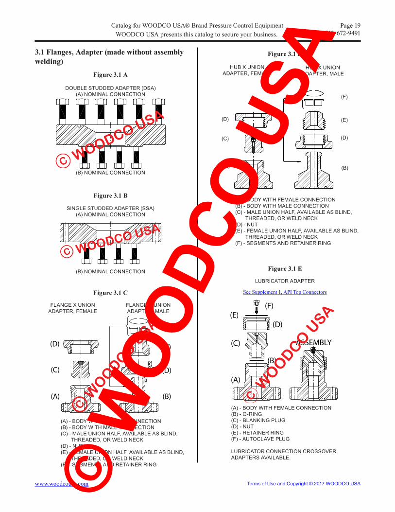
Figure 3.1 A
DOUBLE STUDDED ADAPTER (DSA) (A) NOMINAL CONNECTION
Figure 3.1 B
SINGLE STUDDED ADAPTER (SSA) (A) NOMINAL CONNECTION
Figure 3.1 C
FLANGE X UNIONADAPTER, FEMALE
(A) - BODY WITH FEMALE CONNECTION(B) - BODY WITH MALE CONNECTION(C) - MALE UNION HALF, AVAILABLE AS BLIND, THREADED, OR WELD NECK(D) - NUT(E) - FEMALE UNION HALF, AVAILABLE AS BLIND, THREADED, OR WELD NECK(F) - SEGMENTS AND RETAINER RING
(B) NOMINAL CONNECTION
(B) NOMINAL CONNECTION
FLANGE X UNIONADAPTER, MALE
Figure 3.1 D
HUB X UNIONADAPTER, FEMALE
(A) - BODY WITH FEMALE CONNECTION(B) - BODY WITH MALE CONNECTION(C) - MALE UNION HALF, AVAILABLE AS BLIND, THREADED, OR WELD NECK(D) - NUT(E) - FEMALE UNION HALF, AVAILABLE AS BLIND, THREADED, OR WELD NECK(F) - SEGMENTS AND RETAINER RING
HUB X UNIONADAPTER, MALE
(D)
(C)
(A)
(F)
(E)
(D)
(B)
Figure 3.1 E
(A) - BODY WITH FEMALE CONNECTION(B) - O-RING(C) - BLANKING PLUG(D) - NUT(E) - RETAINER RING(F) - AUTOCLAVE PLUG LUBRICATOR CONNECTION CROSSOVER ADAPTERS AVAILABLE.
LUBRICATOR ADAPTER
3.1 Flanges, Adapter (made without assembly welding)
See Supplement 1, API Top Connectors
WOODCO USA presents this catalog to secure your business.Catalog for WOODCO USA® Brand Pressure Control Equipment
WOODCO USA
C
WOODCO USA
C
(D)
(C)
(A)
(F)
(E)
(D)
(B)
WO
OD
CO
US
AC
WO
OD
CO
US
AC
WO
ODCO
USA
C
(D)
(C)
(A)
(F)(E)
ASSEMBLY
(B)
WO
ODCO
USA
C
© W
OODC
O US
A

www.woodcousa.com Terms of Use and Copyright © 2017 WOODCO USA
Page 20Phone: 713-672-9491
Figure 3.2 A
FLANGE ADAPTER SPOOL
(A) NOMINAL CONNECTION
(B) NOMINAL CONNECTION
OAL = MINIMUM LENGTH TO PROVIDE ADEQUATE WORKING CLEARANCE. SPECIFY ADDITIONAL LENGTH IF REQUIRED.
Figure 3.2 B
FLANGE X STUDDED ADAPTER SPOOL
(A) NOMINAL FLANGE CONNECTION
(B) NOMINAL STUDDED CONNECTION
OAL = MINIMUM LENGTH TO PROVIDE ADEQUATE WORKING CLEARANCE. SPECIFY ADDITIONAL LENGTH IF REQUIRED.
Figure 3.2 C
FLANGE X HUB ADAPTER SPOOL
(A) NOMINAL FLANGE CONNECTION
(B) NOMINAL HUB CONNECTION
OAL = MINIMUM LENGTH TO PROVIDE ADEQUATE WORKING CLEARANCE. SPECIFY ADDITIONAL LENGTH IF REQUIRED.
Figure 3.2 DHUB X HUB ADAPTER SPOOL
(A) NOMINAL CONNECTION
(B) NOMINAL CONNECTION
OAL = MINIMUM LENGTH TO PROVIDE ADEQUATE WORKING CLEARANCE. SPECIFY ADDITIONAL LENGTH IF REQUIRED.
3.2 Spools, Adapter (made without assembly welding)
WOODCO USA presents this catalog to secure your business.Catalog for WOODCO USA® Brand Pressure Control Equipment
OALMIN.
WOODCO USA
C
OALMIN.
WOODCO USA
C
OALMIN.
WOODCO USA
C
OALMIN.
WOODCO USA
C
© W
OODC
O US
A

www.woodcousa.com Terms of Use and Copyright © 2017 WOODCO USA
Page 21Phone: 713-672-9491
Figure 3.3 A
FLANGE X STUDDED DRILLING SPOOL (SDS) (STUDDED OUTLETS)
Figure 3.3 B
SPECIFY ALL NOMINAL CONNECTIONS
OAL = MINIMUM LENGTH TO PROVIDE ADEQUATE WORKING CLEARANCE. OUTLETS SHOWN CENTERED. SPECIFY ADDITIONAL LENGTH IF REQUIRED. *H = SPECIFY ANY ADDITIONAL LENGTH AND THIS DIMENSION FOR OUTLETS NOT CENTERED BETWEEN END CONNECTIONS.
STUDDED DRILLING SPOOL (SDS) (STUDDED OUTLETS)
SPECIFY ALL NOMINAL CONNECTIONS
OAL = MINIMUM LENGTH EQUAL TO LARGEST OUTLET NOMINAL FLANGE DIAMETER PLUS ANY REQUIREMENT FOR NECESSARY STUD THREAD ENGAGEMENT. SPECIFY ADDITIONAL LENGTH IF REQUIRED.
*H = SPECIFY ANY ADDITIONAL LENGTH AND THIS DIMENSION FOR OUTLETS NOT CENTERED BETWEEN END CONNECTIONS.
3.3 Spools, Drilling (made without assembly welding)
WOODCO USA presents this catalog to secure your business.Catalog for WOODCO USA® Brand Pressure Control Equipment
H*
OUTLETEXTENSION
OUTLETEXTENSION
OAL
WOODCO USA
C
H*
OAL
OUTLETEXTENSION
OUTLETEXTENSION
WOODCO U
SA
C
© W
OODC
O US
A

www.woodcousa.com Terms of Use and Copyright © 2017 WOODCO USA
Page 22Phone: 713-672-9491
Figure 3.4 A
Figure 3.4 C
FLANGE SPACER SPOOL (FSS)MINIMUM LENGTH
(A) NOMINAL CONNECTION
(B) NOMINAL CONNECTION MIN = MINIMUM LENGTH TO PROVIDE ADEQUATE WORKING CLEARANCE
FLANGE SPACER SPOOL (FSS)WITH HOIST RING ON 2 FLANGES
FOR HORIZONTAL LIFT
FLANGE SPACER SPOOL (FSS)WITH 2 HOIST RINGS ON 1 FLANGE
FOR VERTICAL LIFT
SPOOLS MAY HAVE 3 TAPPED LOCATIONSTO ALLOW HORIZONTAL AND VERTICAL LIFT
3.4 Spools, Spacer (Riser Spools made with-out assembly welding)
The central body diameter of longer spacer spools made without assembly welding may have a larger diameter to provide greater column strength. Larger diameters may still allow connecting bolt insertion from behind the flange.
Figure 3.4 D
Figure 3.4 B
FLANGE SPACER SPOOL (FSS)LENGTH TO 10 FEET
(A) NOMINAL CONNECTION
(B) NOMINAL CONNECTION OAL = LENGTH SPECIFIED
As an alternate to welding pad eyes, Flange Spacer Spools may have flanges tapped on their O.D. to accept Safety Hoist Rings for lifting. WOODCO USA makes Safety Hoist Rings available as an extra cost accessory at customer request.
HEAVY DUTY SAFETY HOIST RING
Figure 3.4 E
Any single Safety Hoist Ring used will have a capacity exceeding the weight of the spool.
WOODCO USA presents this catalog to secure your business.Catalog for WOODCO USA® Brand Pressure Control Equipment
OALMIN
WOODCO USA
C
OAL
WO
OD
CO
USA
C
WOODCO USA
C
WOODCO USA
C
WOODCO USA
C
© W
OODC
O US
A

www.woodcousa.com Terms of Use and Copyright © 2017 WOODCO USA
Page 23Phone: 713-672-9491
Figure 3.5 A Figure 3.5 C
FLANGE X STUDDED CROSS(FLOW CROSS)
OAL = MINIMUM OR LENGTH SPECIFIED
(A) RUN FACENOMINAL CONNECTION
STUDDED CROSS
STUDDED TEE
3.5 Crosses and Tees (made without assembly welding).
Figure 3.5 DFigure 3.5 B
FLANGE X STUDDED TEE(FLOW TEE)
OAL = MINIMUM OR LENGTH SPECIFIED
See the Slide Rule for Studded Cross, Tee, and Elbow Dimensions at: www.woodcousa.com.
WOODCO USA can manufacture many other customer specified configurations without assembly welding.
(B) RUN FACENOMINAL CONNECTION
(C) OUTLET FACENOMINAL CONNECTION
(D) OUTLET FACENOMINAL CONNECTION
(A) RUN FACENOMINAL CONNECTION
(B) RUN FACENOMINAL CONNECTION
(C) OUTLET FACENOMINAL CONNECTION
(D) OUTLET FACENOMINAL CONNECTION
(A) RUN FACENOMINAL CONNECTION
(B) RUN FACENOMINAL CONNECTION
(C) OUTLET FACENOMINAL CONNECTION
(A) RUN FACENOMINAL CONNECTION
(B) RUN FACENOMINAL CONNECTION
(C) OUTLET FACENOMINAL CONNECTION
WOODCO USA presents this catalog to secure your business.Catalog for WOODCO USA® Brand Pressure Control Equipment
OAL(C)
(B)
(A)
(D)
WOODCO U
SA
C
(B)
OAL
(A)
(C) (D)
WOODCO USAC
WO
OD
CO
USA
C
WO
ODCO
USA
C
(A)
(B)
(C) (D)
WOODCO U
SA
C
(A)
(B) SEE BELOW
(C)
WOODCO U
SA
C
© W
OODC
O US
A

www.woodcousa.com Terms of Use and Copyright © 2017 WOODCO USA
Page 24Phone: 713-672-9491
Figure 3.6 ASTUDDED MODULAR MANIFOLD BUFFER TOP VIEW
Figure 3.6 BHORIZONTAL (SIDE VIEW) CUTAWAY
3.6 Choke Manifold Equipment (made without assembly welding)
WOODCO USA can supply all types of manifold fittings made without assembly welding. A variety of studded and flanged parts can allow the assembly of almost any manifold configuration, including exten-sive buffer systems.
Figure 3.7 A
3.7 Special Purpose Equipment (made without assembly welding)
Figure 3.7 B
STUDDED 45° 4-WAY CROSS
WOODCO USA can design special purpose equipment at customers request, or WOODCO USA can manufacture equipment to customer supplied specifications and drawings.
5 WAY CROSS - 4 WAY STUDDED WITH FLANGE TOP OUTLET
WOODCO USA
C
WOODCO USA presents this catalog to secure your business.Catalog for WOODCO USA® Brand Pressure Control Equipment
WOODCO USAC
WOODCO USAC
WOODCO U
SA
C
WOODCO U
SA
C
© W
OODC
O US
A

www.woodcousa.com Terms of Use and Copyright © 2017 WOODCO USA
Page 25Phone: 713-672-9491
Figure 3.7 C
STUDDED TRANSMITTER ADAPTER FLANGE
PUMP-IN SUB WITH STUDDED OUTLETS
Figure 3.7 EFigure 3.7 D
FLANGED X STUDDED FRAC HEAD “GOAT HEAD” WITH REPLACEABLE FIGURE UNION ADAPTERS
WOODCO USA can assist buyers in determining the detailed dimensions required for each individual configuration. WOODCO USA can manufacture components, and assemble and test complete equipment.
DESIGN MINIMIZES WASHING. FLUID PUMPED IN FROM OPPOSITE SIDES CUSHIONS BLAST
REPLACEABLE FLANGE X UNION
ADAPTER
TARGET FLANGE TO ABSORB
PUMP-IN BLAST
WOODCO USA
C
WOODCO U
SA
C
REPLACEABLEFLANGE X UNION
ADAPTERTARGET FLANGE
TO ABSORBPUMP-IN BLAST
WO
OD
CO
US
A
C
WOODCO USA presents this catalog to secure your business.Catalog for WOODCO USA® Brand Pressure Control Equipment
© W
OODC
O US
A

www.woodcousa.com Terms of Use and Copyright © 2017 WOODCO USA
Page 26Phone: 713-672-9491
MEASURE BOLT HOLE DIAMETER ON OPEN FACE FLANGES. (MEASURE BOLT DIAMETER ON STUDDED FACE FLANGES AND ADD 1/8” TO OBTAIN HOLE DIAMETER).
MEASURE OUTSIDE DIAMETER (O.D.) or CIRCUMFERENCE (Cir.) AND MEASURE BOLT CIRCLE (B.C.)
4.0 Worksheets
4.1 Flange Identification Worksheet
To identify Flange End nominal connections, obtain the information indicated on this form and provide this information to WOODCO USA, or see Flange Slide Rule Program at: www.woodcousa.com.
OUTSIDE DIAMETER
(O.D.)
BOLTCIRCLE
(B.C.)
FLANGETHICKNESS
BOLT HOLE DIAMETER(OR STUD
DIAMETER +1/8”)
NUMBEROF
HOLES.
RING GROOVEPITCH
DIAMETER
FLG 1. FLG 2.
MEASURE BOLT HOLE DIAMETER ANDCOUNT NUMBER OF HOLES
O.D. MEASURE OUTSIDE DIAMETER (FOR INACCESSIBLE FLANGE FACES, MEASURE CIRCUMFERENCE OF FLANGE WITH A TAPE MEASURE AND DIVIDE THIS MEASUREMENT BY 3.1416 [p] TO GET THE O.D.).
TO MEASURE B.C., MEASURE FROM INSIDE EDGE OF ONE HOLE TO OUTSIDE EDGE OF OPPOSITE HOLE.
COUNT NUMBER OF HOLES.
MEASURE FROM INSIDE EDGE OF RING GROOVE ON ONE SIDE , TO OUTSIDE EDGE OF RING GROOVE ON OPPOSITE SIDE.
USING AN ACCURATE SCALE
Cir. B.C.
BOLT HOLEDIAMETERNO.
OFHOLES
MEASURE RING GROOVE PITCH DIAMETER AND MEASURE THICKNESS
WOODCO USA presents this catalog to secure your business.Catalog for WOODCO USA® Brand Pressure Control Equipment
RING THICKNESS
FOR SWIVEL FLANGE
TOTALTHICKNESS(INCLUDE
ANY RAISED FACE
PRESENT)
P.D.
© W
OODC
O US
A

www.woodcousa.com Terms of Use and Copyright © 2017 WOODCO USA
Page 27Phone: 713-672-9491
4.2 Hub Identification Worksheet
To determine the nominal size and pressure rating of any existing Hub Connection, measure the Hub di-mensions indicated on the drawing below and provide this information to WOODCO USA, or See Hub Slide Rule Program at: www.woodcousa.com.
MEASURE RING GROOVE PITCH DIAMETER BY MEASURING FROM INSIDE EDGE OF RING GROOVE ON ONE SIDE, TO OUTSIDE EDGE OF RING GROOVE ON OPPOSITE SIDE.
NOTE:
HUBOUTSIDE DIAMETER
RING GROOVEPITCH DIAMETER
HUBTHICKNESS
BORE INSIDE DIAMETER
HUB 1. HUB 2. HUB 3. HUB 4.
To obtain more complete information about Hub Connection Equipment, see the WOODCO USA Catalog for Pressure Control Equipment at: www.woodcousa.com.
WOODCO USA presents this catalog to secure your business.Catalog for WOODCO USA® Brand Pressure Control Equipment
O.D.
P.D.
I.D.
USING A SCALE OR TAPE MEASURE
MEASURE HUB OUTSIDE DIAMETER
MEASURE RING GROOVE PITCH DIAMETER
MEASUREHUB
THICKNESS
THICKNESSAT O.D.
MEASURE INSIDE DIAMETER
© W
OODC
O US
A

www.woodcousa.com Terms of Use and Copyright © 2017 WOODCO USA
Page 28Phone: 713-672-9491
A 1.0 General
WOODCO USA urges Buyers to choose to deal only with API Licensed Manufacturers.
See Appendix B for a statement on Why you should look for the API Monogram and License number on API products.
A 2.0 API Spec 6A
Pressure Control Equipment
Buyers should specify on each purchase order for API Spec 6A Pressure Control Equipment that:
“All items on this purchase order shall comply with every detail of all the applicable sections of API Spec 6A.”
Additionally, if the manufacturer chosen as supplier holds an API Spec 6A License, add these words:
“The API Monogram and the Manufacturers’ License number shall appear on each and every piece of equipment when allowed by API.”
Buyers should describe the equipment by terms and nominal size and pressure ratings appearing in API Spec 6A. Descriptions for each or all equipment items should also include:
PSL (Product Specification Level) 1, 2, 3, 3G, or 4. (See A 3.0)
Service Temperature
Minimum temperature represents the lowest ambient temperature that the equipment may experience. Maximum temperature represents the highest temperature of the fluid that may flow through the equipment.
Supplemental Requirements
Buyers should clearly define, at the time of order, any requirements which exceed or differ from API Spec 6A.
Appendix A
Guide to Order Placement
Temperature Operating RangeClassification * ( Degrees Fahrenheit [°F] )
Min. Max.K -75 to 180L -50 to 180N -50 to 140P -20 to 180R Room TemperatureS 0 to 140T 0 to 180U 0 to 250V 35 to 250
X** 0 to 350 Y** 0 to 650
* PURCHASER MAY COMBINE TEMPERATURE CLASSES e.g. KU, -75 TO 250 °F
** MAY REQUIRE DERATING
Material class
Minimum Material RequirementsBody & Flange
AA-General Service Carbon or low alloy steelBB-General Service Carbon or low alloy steelCC-General Service Stainless steel
DD-Sour Service a Carbon or low alloy steel b
EE-Sour Service a Carbon or low alloy steel b
FF-Sour Service a Stainless steel b
HH-Sour Service a CRA bcd
a As defined by NACE Standard MR0175/ISO 15156.
b In compliance with NACE Standard MR-01-75/ISO 15156.
c CRA required on retained fluid wetted surfaces only; CRA cladding of low allow or stainless steel permitted.
d CRA as defined in API 6A latest edition. NACE MRO175/ISO 15156 definition of CRA does not apply.
WOODCO USA presents this catalog to secure your business.Catalog for WOODCO USA® Brand Pressure Control Equipment
© W
OODC
O US
A

www.woodcousa.com Terms of Use and Copyright © 2017 WOODCO USA
Page 29Phone: 713-672-9491
Documentation
Buyers should specifically request any desired documentation, as applicable, at the time of order, such as:
Certificate of Compliance with API Spec 6A and/or the terms of the purchase order.
Material Test Reports
Heat Treat Records
Non-destructive Test Reports: PT - Liquid Penetrant ExaminationMT - Magnetic Particle ExaminationUT - Ultrasonic Volumetric ExaminationRT - Radiographic VolumetricExamination
Hydrostatic Test Report and/or Chart Recording of Hydrostatic Test (API Spec 6A omits hydrostatic test of Loose Connectors for all PSL’s).
A 3.0 Product Specification Level
API Spec 6A specifically states, product specification levels do not apply to ring gaskets or studs and nuts.
A summary of what PSL’s designate follows:
PSL-1 Equipment meets the minimum requirements of API Spec 6A for:
Design
Specification
Qualification, CVN testing for service temperature -50° F and below.
PSL-1 Continued
Process
Inspection
Hydrostatic Test (except for Loose Connectors.
PSL-2 Equipment meets all the requirements of API Spec 6A PSL-1 and:
Controls the limits of variance between the material qualification test coupon and the production material. CVN testing for service temperature -20° F and below.
Volumetric inspection of welds (RT or UT).
Magnetic particle inspection of accessible well wetted surfaces.
PSL-3 Equipment meets all the requirements of API Spec 6A PSL-2 and:
Restricts the tolerance of material chemistry.
Increases the maximum size of the material qualification test coupon in relation to the section thickness of the equipment components. CVN testing for all service temperatures.
Volumetric inspection of all material in body, bonnets, flanges & stems..
Wet Magnetic Particle inspection of all accessible surfaces.
Hydrostatic Test time extended (except for Loose Connectors).
PSL-3G includes all the requirements of PSL 3 plus additional practices described in API 6A, Annex A. PSL-3G designates an additional gas-testing requirement of assembled equipment.
Appendix A (continued)
WOODCO USA presents this catalog to secure your business.Catalog for WOODCO USA® Brand Pressure Control Equipment
© W
OODC
O US
A

www.woodcousa.com Terms of Use and Copyright © 2017 WOODCO USA
Page 30Phone: 713-672-9491
PSL-4 Equipment meets all the requirements of API Spec 6A PSL-3 and:
Increases the maximum size of the material qualification test coupon in relation to the section thickness of the equipment components.
Prohibits welding except for overlay/inlay of corrosion resistant alloy on well wetted surfaces.
Gas testing of assembled equipment.
A 4.0 Order Placement Worksheet
WOODCO USA provides a worksheet on Page 31 of this catalog for the convenience of buyers of either API Spec 6A or API Spec 16A equipment. Buyers may print and use this form directly or it may serve as a draft for buyers who want to have such a document on proprietary forms.
For the convenience of buyers who may need to identify connections in the field, see:
Page 25, Flange Identification WorksheetorPage 26, Hub Identification Worksheet.
On the internet at: www.woodcousa.com.
See also: Web Site Tools Flange Slide Rule Program Hub Slide Rule Program
A 5.0 The API Spec 6A Document
WOODCO USA furnishes the information concerning API Spec 6A in this appendix as a reference only. Buyers interested in becoming familiar with API Spec 6A may obtain a copy of the document by contacting:
Global Engineering Documents: Phone Orders: 1-800-854-7179 (Toll-free in the U.S. and Canada) 303-397-7956 (Local and International) Fax Orders: 303-397-2740 Online Orders: www.global.ihs.comProduct Number: GX06A19
Appendix A (continued)
WOODCO USA presents this catalog to secure your business.Catalog for WOODCO USA® Brand Pressure Control Equipment
© W
OODC
O US
A

www.woodcousa.com Terms of Use and Copyright © 2017 WOODCO USA
Page 31Phone: 713-672-9491
A 5.0 API Spec 16A Pressure Control Equipment Buyers should specify on each purchase order for API Spec 16A Pressure Control Fittings that:
“All items on this purchase order shall comply with every detail of all applicable sections of API Spec 16A.”
Additionally, if the manufacturer chosen as supplier holds an API Spec 16A License, add these words:
“The API Monogram and the Manufacturers’ License number shall appear on each and every piece of equipment when allowed by API.”.
Buyers should describe the equipment by terms and nominal size and pressure ratings appearing in API Spec 16A. Descriptions for each or all equipment items should also include:
Service TemperatureMinimum temperature represents the lowest ambient temperature that the equipment may experience. Maximum temperature represents the highest temperature of the fluid that may flow through the equipment without derating.
Supplemental Requirements
Buyers should clearly define, at the time of order, any requirements which exceed or differ from API Spec 16A.
A 6.0 Order Placement Worksheet
WOODCO USA provides a Worksheet on the following page of this catalog for the convenience of buyers of either API Spec 6A or API Spec 16A equipment. Buyers may print and use this form directly or it may serve as a draft for buyers who want to have such a document on proprietary forms.
For the convenience of buyers who may need to identify connections in the field, see:
Page 25, Flange Identification Worksheet
or
Page 26, Hub Identification Worksheet.
On the internet at: www.woodcousa.com.
See also: Web Site Tools Flange Slide Rule Program Hub Slide Rule Program
A 7.0 The API Spec 16A Document
WOODCO USA furnishes the information concerning API Spec 16A in this appendix as a reference only. Buyers interested in becoming familiar with API Spec 16A may obtain a copy of the document by contacting:
Online Orders: www.techstreet.com
Temperature Classification Operating Range (°F)
T-75 -75 to 250T-20 -20 to 250 T- 0 - 0 to 250
Appendix A (continued)
WOODCO USA presents this catalog to secure your business.Catalog for WOODCO USA® Brand Pressure Control Equipment
© W
OODC
O US
A

www.woodcousa.com Terms of Use and Copyright © 2017 WOODCO USA
Page 32Phone: 713-672-9491
Appendix A (continued)
Order Placement WorksheetDESCRIPTION OF PRODUCT
API 6A PRODUCTAPI 6A MONOGRAM REQUIRED
PRODUCT SPECIFICATION LEVEL
PSL 1 PSL 2 PSL 3 PSL 3G PSL 4
SERVICE TEMPERATURE(Circle one or two to cover temperature range required).
AA-General Service Carbon or low alloy steelBB-General Service Carbon or low alloy steelCC-General Service Stainless steelDD-Sour Service a Carbon or low alloy steel b
EE-Sour Service a Carbon or low alloy steel b
FF-Sour Service a Stainless steel b
HH-Sour Service a CRA bcd
* As defined by NACE Standard MR0175/ISO 15156** In compliance with NACE Standard MR-01-75/ISO 15156.
MATERIAL CLASS(Circle one)
SUPPLEMENTAL REQUIREMENTS
NON-DESTRUCTIVE TEST REPORTS .... PT , MT , UT , RT *Required for API Spec 16A Equipment bearing the API Monogram. ** Not required for API 6A Loose Connectors.
API 16A PRODUCTAPI 16A MONOGRAM REQUIRED
SERVICE TEMPERATURE (Circle one)
Temperature
Classification Operating Range (°F)
T-75 -75 to 250
T-20 -20 to 250
T- 0 - 0 to 250
SUPPLEMENTAL REQUIREMENTS
Temperature Operating RangeClassification * ( Degrees Fahrenheit [°F] )
Min. Max.K -75 to 180L -50 to 180N -50 to 140P -20 to 180R Room TemperatureS 0 to 140T 0 to 180U 0 to 250V 35 to 250
X** 0 to 350 Y** 0 to 650
* PURCHASER MAY COMBINE TEMPERATURE CLASSES e.g. KU, -75 TO 250 °F ** MAY REQUIRE DERATING
HYDROSTATIC TEST REPORTS . . . . . . orHYDROSTATIC TEST RECORD CHART **
DOCUMENTATION REQUIRED (Check all that apply) (WOODCO USA furnishes documentation without request)CERTIFICATE OF COMPLIANCE*. . MATERIAL TEST REPORT . . . . . . . . HEAT TREAT RECORDS . . . . . . . . . .
(Specify any stainless steel or "CRA" inlay of ring grooves, lifting eyes,etc.)
(Specify any stainless steel or "CRA" inlay of ring grooves, lifting eyes,etc.)
WOODCO USA presents this catalog to secure your business.Catalog for WOODCO USA® Brand Pressure Control Equipment
© W
OODC
O US
A

www.woodcousa.com Terms of Use and Copyright © 2017 WOODCO USA
Page 33Phone: 713-672-9491
WHY YOU SHOULD LOOK FOR THE API MONOGRAM AND LICENSE NUMBER ON “API” PRODUCTS.
Manufacturers who want to apply the API monogram on their equipment and materials must apply to API for a license to do so. If API determines, through a Quality System Survey, that these manufacturers have the capability to produce products that consistently conform to API specifications, API shall license these manufacturers to use the API monogram and their license number on specific products made at specific locations. Although any manufacturer may claim that its products meet API specifications without monogramming them, only manufacturers with a license from API can apply the API monogram to their products.
WHEN THE API MONOGRAM, IN CONJUNCTION WITH THE MANUFACTURER’S LICENSE NUMBER, ACTUALLY APPEARS ON THE PRODUCT, IT CONSTITUTES A WARRANTY BY THE LICENSED MANUFACTURER (LICENSEE) TO THE AMERICAN PETROLEUM INSTITUTE AND TO THE PURCHASER OF SUCH EQUIPMENT OR MATERIALS: THAT THIS PRODUCT COMPLIES IN EVERY DETAIL WITH THE APPLICABLE STANDARDS AND SPECIFICATIONS. NO SUCH WARRANTY TO API EXISTS WHEN THE MONOGRAM DOES NOT APPEAR.
API DOES NOT RECOGNIZE CLAIMS ABOUT API-SPECIFIED PRODUCTS TO WHICH MANUFACTURERS DO NOT APPLY THE MONOGRAM. USERS WHO WANT AN “API STANDARD PRODUCT” FROM AN API LICENSED MANUFACTURER SHOULD REQUIRE IN THEIR PURCHASE ORDER THAT THE MONOGRAM AND THE MANUFACTURER’S LICENSE NUMBER APPEAR ON THE PRODUCT ITSELF.
Appendix B
Product marking with License Number in conjunction with monogram
API Monogram applied to or on the product by Licensee.
The API evaluation and licensing system has superiority to other quality system evaluations -- such as ISO 9000 -- because API evaluators have product knowledge and have the capability to verify that the manufacturer’s quality system, if applied, assures a product that meets API specifications. In contrast, other systems do not require evaluators to have product knowledge.
WOODCO USA has license certificates, API 6A, 16A, 17D, and 7K. For a list of manufacturers API has licensed to date, see The API Composite List, Latest Edition, updated weekly, on-line at http://compositelist.api.org/.
Figure B.1
6A XXXX
Applicable API specification for the Monogrammed product, e.g. 6A.
License Number issued by API, identifying the Manufacturer and the Licensed facility.
WOODCO USA presents this catalog to secure your business.Catalog for WOODCO USA® Brand Pressure Control Equipment
© W
OODC
O US
A

www.woodcousa.com Terms of Use and Copyright © 2017 WOODCO USA
Page 34Phone: 713-672-9491
Appendix C
WOODCO USA presents this catalog to secure your business.Catalog for WOODCO USA® Brand Pressure Control Equipment
© W
OODC
O US
A

www.woodcousa.com Terms of Use and Copyright © 2017 WOODCO USA
Page 35Phone: 713-672-9491
Appendix D
WOODCO USA presents this catalog to secure your business.Catalog for WOODCO USA® Brand Pressure Control Equipment
© W
OODC
O US
A

www.woodcousa.com Terms of Use and Copyright © 2017 WOODCO USA
Page 36Phone: 713-672-9491
Appendix E
WOODCO USA presents this catalog to secure your business.Catalog for WOODCO USA® Brand Pressure Control Equipment
© W
OODC
O US
A

Terms of Use
Welcome to www.woodcousa.com, the official website of WOODCO USA (“WOODCO”). www.woodcousa.com provides services to you subject to the following conditions. If you visit www.woodcousa.com, you accept these conditions. Please read them carefully. In addition, when you use any current or future woodcousa.com service or download WOODCO USA software, you also agree to comply with any of these conditions that may apply to such service or software use.
WOODCO USA may change, add, or remove portions of its website at any time. WOODCO USA also may impose limits on certain features and services or restrict access to all or any part of its website without notice or liability.
WOODCO USA intends its website (the “Content”) for your personal use only.
All materials published on the WOODCO USA website have copyright protection pursuant to U.S. and international copyright laws. You may not modify, publish, transmit, participate in the transfer or sale of, reproduce (except as provided in Paragraph 4 below), create new works from, distribute, perform, display, or in any way exploit any of the Content in whole or in part. You shall abide by all additional copyright notices, information, and other restrictions associated with any of the Content.
You may download or copy the Content and other downloadable items forming parts of the Content for personal use only, provided that you maintain all copyright and other notices contained therein. You may not copy or store any Content for other than personal use without prior written permission from an officer of WOODCO USA.
WOODCO USA does not assume liability for any errors or omissions in the Content, or in the transmission or delivery of all or any part thereof, or for any damages arising there from. You acknowledge sole responsibility (sole risk) for any reliance you may have in the Content or actions you may take relying upon any of the Content. WOODCO USA makes every effort to assure the accuracy of the Content, but, WOODCO USA MAKES THE CONTENT AVAILABLE TO YOU ON AN “AS IT APPEARS” BASIS, WITHOUT WARRANTIES OF ANY KIND, EITHER EXPRESS OR IMPLIED, INCLUDING, WITHOUT LIMITATION, ANY WARRANTIES OF TITLE OR IMPLIED WARRANTIES OF MERCHANTABILITY OR FITNESS FOR A PARTICULAR PURPOSE. YOU HEREBY ACKNOWLEDGE THAT YOU USE THE CONTENT AT YOUR SOLE RISK.
You shall have no rights to any of the proprietary rights associated with any of the Content.
WOODCO USA may, in its sole discretion, terminate or suspend access to all or part of the Content for any reason, including without limitation, breach or assignment of this Agreement.
This Agreement originates in Houston, Texas and any interpretation and/or enforcement shall comply with Texas law. Any action to enforce this agreement shall occur in, and only in, the federal or state courts located in Harris County, Texas.
Privacy - Please review our Privacy Policy, which also governs your visit to woodcousa.com, to understand our practices.
Please direct all questions to: [email protected]
Copyright Notice 1999 - 2017, WOODCO USA.
WOODCO USA will enforce all rights under copyright law, regarding all photographs, graphics, written materials or other content appearing on this website, the legally protected property of WOODCO USA. WOODCO USA prohibits reproduction or re-use of any kind, other than that described in “Terms of Use” above, without written permission from an officer of WOODCO USA. Submit all requests for re-use of copyrighted materials in writing to: [email protected]© W
OODC
O US
A