wonderful communication, mobile life. · wonderful communication, mobile life. welcome to use...
TRANSCRIPT

Wonderful Communication, Mobile Life.
Welcome to use ETS1000 Series FWT from Huawei Technologies Co., Ltd.
HUAWEI ETS1000 Series Fixed Wireless Terminal
User Guide

Copyright © 2007 Huawei Technologies Co., Ltd.
All Rights Reserved
No part of this manual may be reproduced or transmitted in any form or by any means without prior written consent of Huawei Technologies Co., Ltd.
Trademarks
and HUAWEI are trademarks of Huawei Technologies Co., Ltd.All other trademarks mentioned in this manual are the property of their respective holders.
Notice
The information in this manual is subject to change without notice. Every effort has been made in the preparation of this manual to ensure accuracy of the contents, but all statements, information, and recommendations in this manual do not constitute the warranty of any kind, expressed or implied.

i
Contents 1 Precautions ............................................................................................................................1 2 Overview ...............................................................................................................................2
Unpacking Check ..........................................................................................................2 Appearance of ETS1000 Series FWT Component .......................................................2
3 Panel and Port .......................................................................................................................6 Front View .....................................................................................................................6 Rear View ......................................................................................................................7
4 Installation.............................................................................................................................9 Connecting Terminal .....................................................................................................9 Installing the Outdoor Antenna ...................................................................................16 Mounting the Terminal ................................................................................................22
5 General Functions ...............................................................................................................24 Preparation for Booting ...............................................................................................24 Using R-UIM Card (Optional) ....................................................................................24 Placing Calls ................................................................................................................25 Answering Calls ..........................................................................................................26 Managing the Spare Battery ........................................................................................27
6 Signal Tone..........................................................................................................................28 7 Advanced Functions............................................................................................................29
Supplementary Services ..............................................................................................29 Adjusting the Voice Volume ........................................................................................30
8 Facsimile Function and Usage Description ........................................................................32 Sending Facsimile .......................................................................................................32 Receive Facsimile........................................................................................................33
9 Troubleshooting...................................................................................................................34 10 Technical Parameters ........................................................................................................36 11 Description of ETS1000 Series FWT ...............................................................................37

1
1 Precautions
To use your ETS1000 Series Fixed Wireless Terminals (hereinafter referred to as ETS1000 Series FWT) in a correct, efficient, and safe way, and to avoid the damage caused by improper operations, you are recommended to:
1. Read this manual carefully and follow the guidelines to install and use the device. 2. Make sure to power off the ETS1000 Series FWT and disconnect external power
supply before moving or cleaning it. 3. Ensure the good ventilation of ETS1000 Series FWT in operation, please put the host
and power adapter at a cool place with good ventilation, and take care not to cover the host or the power adapter or expose them to direct sunlight. In addition, do not place any objects on them, or expose them to water, or place them near flammable and explosive sources and fire.
4. When lightning, if you use the power adapter, please turn off the FWT and disconnect the power adapter from external power supply. If outdoor antenna is used, please turn off the FWT and do not touch the interface between FWT and antenna.
5. Do not use the external telephone outdoors. 6. Please use the specially designed power adapter and standby batteries to avoid damage
the FWT. Dispose of used batteries according to the instructions 7. Do not attempt to open the chassis regardless of whether the device is properly
working or problems have occurred. In the latter case, the proper measure is to select an authorized maintenance agent to repair the device.
8. If you have any difficulties when installing or using the device, proceed to “Chapter 9 Troubleshooting” for help. If the problem is still unsolved, please contact the local sales agent (or carrier).
9. No organizations or individuals are allowed to make modifications to the device structure or security design, unless authorized by Huawei Technologies Co., Ltd. (hereinafter referred to as Huawei Technologies). Huawei Technologies will not assume any responsibility for any consequences resulted from the modifications without approval.
2
2 Overview
Unpacking Check Check the delivered items against the packing list shown in the table below, and make sure that all the items are in good conditions. If there is any shortage or damage, please contact the local agent as soon as possible.
Commodity Quantity Unit ETS1000 Series FWT host 1 PCS
ETS1000 Series FWT power adapter 1 PCS
Power cord 1 PCS
Phone cable with dual connectors 1 PCS
Spare battery (rechargeable) (optional) 1 Piles
HUAWEI ETS1000 Series FWT Fixed Wireless Terminal User Manual
1 PCS
Certificate of Quality 1 PCS
Note: Spare battery is optional and you can buy it together with the terminal or buy it
alone. ETS1000 Series FWT should be configured with an antenna. Please select either
an indoor or an outdoor antenna depending on the local radio signal strength. For more information, please consult your local sales agent.
If you want to use ETS1000 Series FWT for accessing the internet, you should also purchase the required data suite. For more information, please consult your local agent.
Appearance of ETS1000 Series FWT Component
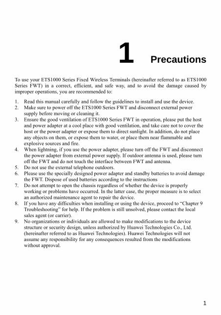
Host Figure 2-1 illustrates an ETS1000 Series FWT host.
3
Figure 2-1 ETS1000 Series FWT host
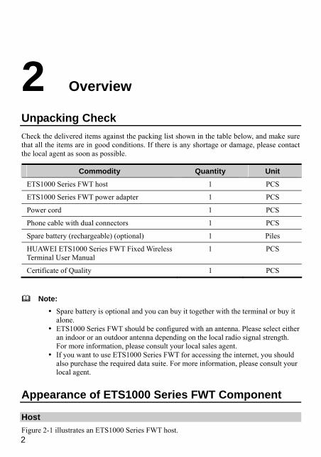
Power Adapter and Spare Battery ETS1000 Series FWT power adapter consists of power adapter module and its power cord as shown in Figure 2-2.
1) Power adapter module 2) Power cord
Figure 2-2 ETS1000 Series FWT power adapter
Figure 2-3 illustrates the spare battery for ETS1000 Series FWT:

4
Figure 2-3 Spare battery for ETS1000 Series FWT
Caution: While using an external power supply to charge the battery, the charging must
last for more than five minutes if the battery has been left unused for a long period.
If the FWT is left unused for a long period, you need to take the spare battery out of the FWT.
Antenna and Feeder
Indoor omni antenna Figure 2-4 illustrates an indoor omni antenna for ETS1000 Series FWT:
Figure 2-4 Indoor omni antenna for ETS1000 Series FWT
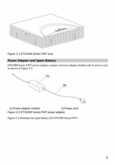
Outdoor directional antenna Figure 2-5 illustrates an outdoor directional antenna for ETS1000 Series FWT:
5
1) Fixing clip 2) Directional antenna 3) Feeder 4) Connector at the host side
Figure 2-5 Outdoor directional antenna for ETS1000 Series FWT
Outdoor omni antenna Figure 2-6 illustrates an outdoor omni antenna for ETS1000 Series FWT:
1) Impedance match 2) Fixing clip 3) Feeder 4) Connector at the host side
Figure 2-6 Outdoor omni antenna for ETS1000 Series FWT

6
3 Panel and Port
Front View Figure 3-1 illustrates the front view of an ETS1000 Series FWT host:
1) Telephone port 1 2) Telephone port 2 3) FWT switch 4) DC input 5) Serial port 6) Antenna port 7) Battery LED 8) Power LED 9) Receive signal strength LED
Figure 3-1 Front view of ETS1000 Series FWT host
The following describes the ports and the LEDs on the host:
Telephone port 1 This port is used to connect the device to an external telephone to provide voice services.
Telephone port 2 This port provides the same functions as telephone port 1 and can connect a telephone in parallel with telephone port 1.

7
FWT switch The switch is used to turn on or turn off the terminal.
DC input This port is used to connect the FWT to power adapter.
Serial port This port connects to the computer to perform data service and is mainly used for maintaining the terminal.
Antenna port This port can be directly connected to an indoor antenna. Also, it can be connected to an outdoor antenna via a feeder cable.
Battery LED When only using the battery (no power adapter) for power supply, Green LED means full electricity supply. Orange LED means medium electricity supply. Orange LED with blinking means poor electricity supply and needs to recharge.
When using external power adapter (with battery installed), Orange LED means the battery is recharging. Green LED means recharging has been finished.
Power LED The green LED means that the power adapter is serving for the FWT.
Receive signal strength LED The receive signal strength is indicated by four LEDs, the number of lightening LEDs indicates the strength of signal.
Rear View Figure 3-2 illustrates the rear view of ETS1000 Series FWT host:
8
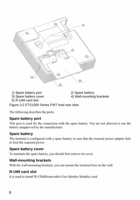
1) Spare battery port 2) Spare battery 3) Spare battery cover 4) Wall-mounting brackets 5) R-UIM card slot
Figure 3-2 ETS1000 Series FWT host rear view
The following describes the ports:
Spare battery port This port is used for the connection with the spare battery. You are not allowed to use the battery unapproved by the manufacturer.
Spare battery The terminal is configured with a spare battery in case that the external power adapter fails to feed the required power.
Spare battery cover To maintain the spare battery, you should first remove its cover.
Wall-mounting brackets With the wall-mounting brackets, you can mount the terminal host on the wall.
R-UIM card slot It is used to install R-UIM(Removable-User Identity Module) card.
9
4 Installation
Connecting Terminal The connection of ETS1000 Series FWT mainly includes installing the spare battery and indoor or outdoor antenna, and connecting the external power adapter, telephone, PC, as well as facsimile set.
Spare battery is mainly used to supply the host with the necessary power in the case that electricity has failed or the external power supply is unavailable.
You should select either an indoor or outdoor antenna depending on the local signal strength. For the installation of outdoor antenna, see the page 16 “Installing the Outdoor Antenna”.
If you want to use the data services like network accessing or device maintenance, you should connect the terminal with a PC. For the connection, see the page 13 “Connecting ETS1000 Series FWT to a PC”.
Removing/Installing a Spare Battery
Note: Make sure that the spare battery has been charged for more than 8 hours before it supplies power for the terminal at the first time. For details about the battery usage, refer to the page 27 “Managing the Spare Battery”.
You should follow these steps to install or remove the spare battery:
Caution: To prevent lightning from injuring human body, please note:
If you use outdoors antenna, remove it before disassembling and installing spare battery.
10
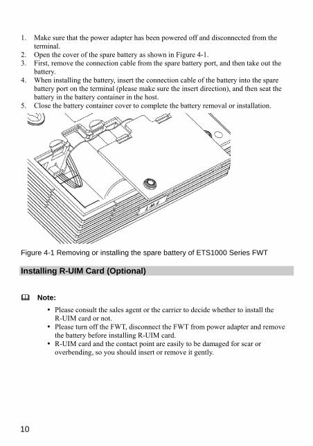
1. Make sure that the power adapter has been powered off and disconnected from the terminal.
2. Open the cover of the spare battery as shown in Figure 4-1. 3. First, remove the connection cable from the spare battery port, and then take out the
battery. 4. When installing the battery, insert the connection cable of the battery into the spare
battery port on the terminal (please make sure the insert direction), and then seat the battery in the battery container in the host.
5. Close the battery container cover to complete the battery removal or installation.
Figure 4-1 Removing or installing the spare battery of ETS1000 Series FWT
Installing R-UIM Card (Optional)
Note: Please consult the sales agent or the carrier to decide whether to install the
R-UIM card or not. Please turn off the FWT, disconnect the FWT from power adapter and remove
the battery before installing R-UIM card. R-UIM card and the contact point are easily to be damaged for scar or
overbending, so you should insert or remove it gently.

11
Figure 4-2 Installing R-UIM card
1. Open the spare battery cover and remove the battery. 2. Insert R-UIM card to the slot as the arrow shows in Figure 4-2.Please put the side that
with a corner cutting backwards and the side with a gold contact point downwards, and then make sure the R-UIM card is completely inserted into the slot.
3. Restore the battery and install the spare battery cover.
Installing Indoor Antenna In an area that signals can be transmitted and received with good quality, you can install an indoor antenna, as shown in Figure 4-3.
Figure 4-3 Installing an indoor antenna for ETS1000 Series FWT
1. Make sure to place the switch of the terminal in the OFF position. 2. Align the indoor antenna with the antenna port on the terminal host in the direction
shown in Figure 4-3, and then screw the antenna, ensuring that the connection is secure.
12
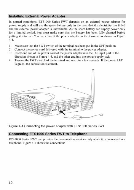
Installing External Power Adapter In normal conditions, ETS1000 Series FWT depends on an external power adapter for power supply and will use the spare battery only in the case that the electricity has failed and the external power adapter is unavailable. As the spare battery can supply power only for a limited period, you must make sure that the battery has been fully charged before putting it into use. You can connect the power adapter to the terminal as shown in Figure 4-4.
1. Make sure that the FWT switch of the terminal has been put in the OFF position. 2. Connect the power cord delivered with the terminal to the power adapter. 3. Insert one end of the power cord of the power adapter into the DC input port in the
direction shown in Figure 4-4, and the other end into the power supply jack. 4. Turn on the FWT switch of the terminal and wait for a few seconds. If the power LED
is green, the connection is correct.
Figure 4-4 Connecting the power adapter with ETS1000 Series FWT
Connecting ETS1000 Series FWT to Telephone ETS1000 Series FWT can provide the conversation services only when it is connected to a telephone. Figure 4-5 shows the connection:

13
Figure 4-5 Connecting ETS1000 Series FWT to a telephone
As shown in Figure 4-5, connect the telephone to a telephone port on the terminal via a cable with an RJ11 connector. The terminal provides two telephone ports respectively numbered 1 and 2. As they are internally interconnected, you can use either of them.
You can use the telephone cable came with the terminal to directly connect the host of the terminal to a telephone and you can also connect another free telephone port to some other telephone set. (The two telephones are in parallel connection and hence use the same number).
Connecting ETS1000 Series FWT to a PC The terminal can be connected to a PC to provide data services.
To support data services, you should purchase the data service suite, in which you can get USB serial cable as shown in Figure 4-6.

14
1) Cable connector-D type-9 pin-male 2) Cable connector-USB-4 pin-male
Figure 4-6 USB serial cable
To maintain and debug the terminal, you should purchase serial communication cable and connect it to a PC, as shown in Figure 4-7.
1) Cable connector-D type-9 pin-male 2) Cable connector-D type-9 pin-female
Figure 4-7 Serial communication cable
Connecting the terminal to PC via a serial communication cable As shown in Figure 4-8, connect one end of the serial communication cable to a PC, insert the other end to the serial port of the terminal, and fasten the captive screw holding it in place, ensuring that the connection is reliable.
Caution: To avoid damaging the device when making connection, make sure to turn off the terminal before making connection and use the special serial cable provided by the manufacturer.

15
Figure 4-8 Connecting ETS1000 Series FWT to a PC via a serial communication cable
Connecting the terminal to PC via a USB port As shown in Figure 4-8, connect the USB end of the serial cable to PC and the other end to the serial port of the terminal and fasten the captive screw holding it in place, ensuring that the connection is reliable.
Caution: To avoid the odds of damaging the device when making connection, make sure to turn off the terminal before making connection and use the specially designed USB serial cable provided by the manufacturer.
Caution: ETS1000 Series FWT can be connected to a telephone and a PC at the same time, but the telephone and data services cannot be manipulated simultaneously. In other words, you can use only one service at a time.
Connecting FWT and Facsimile Set
16
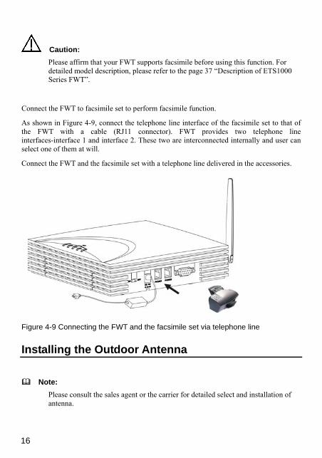
Caution: Please affirm that your FWT supports facsimile before using this function. For detailed model description, please refer to the page 37 “Description of ETS1000 Series FWT”.
Connect the FWT to facsimile set to perform facsimile function.
As shown in Figure 4-9, connect the telephone line interface of the facsimile set to that of the FWT with a cable (RJ11 connector). FWT provides two telephone line interfaces-interface 1 and interface 2. These two are interconnected internally and user can select one of them at will.
Connect the FWT and the facsimile set with a telephone line delivered in the accessories.
Figure 4-9 Connecting the FWT and the facsimile set via telephone line
Installing the Outdoor Antenna
Note: Please consult the sales agent or the carrier for detailed select and installation of antenna.

17
Precautions 1. Normally, the outdoor antenna for ETS1000 Series FWT is directional, but you can
adopt an omni antenna as well. A directional antenna has a higher gain than an omni antenna, but its positioning is somewhat complex. If ETS1000 Series FWT is placed at a place faraway from the base station, it is recommended to use a directional antenna. If it is close to the base station, an omni or indoor antenna can be used.
2. The outdoor antenna should be mounted at a high place outdoors, such as the top of building or hillside. The antenna mast can be made of iron tube, solid wood or bamboo stick, as shown in Figure 4-10.
1) Antenna mast 2) Ground, hill or building top
Figure 4-10 Installing antenna (1)
3. If a directional antenna is installed, it should be kept perpendicular to the ground, as shown in Figure 4-11. If an omni antenna is installed, the antenna mast should be kept upright, as shown in Figure 4-12.
1) Vertical measured from the horizontal ground 2) Ground, hill or building top
Figure 4-11 Installing antenna (2)

18
1) Antenna is Vertical measured from the horizontal ground 2) Ground, hill or building top
Figure 4-12 Installing antenna (3)
4. To ensure the reliable fastening of the antenna, the antenna feeder should be bound with the mast each meter, as shown in Figure 4-13.
1) Fixing clip 2) Cable ties
Figure 4-13 Installing antenna (4)
5. When installing a directional antenna, first position the antenna towards the direction of the base station, as shown in Figure 4-14.

19
Figure 4-14 Installing antenna (5)
6. The antenna for ETS1000 Series FWT should be installed with a lightning rod, which must be well grounded and have a grounding resistance less than 10ohm. Furthermore, the top of the lightning rod must form a 45 degree angle with the outmost point of the antenna, as shown in Figure 4-15.
1) Lightning rod 2) Ground, hill or building top
Figure 4-15 Installing a lightning rod
Caution: Do not use the antenna mast as lightning rod!

20
7. The external antenna should be placed as far as possible from TV antennas.
Connecting Terminal to the Outdoor Antenna After fixing the outdoor antenna, connect the feeder of the antenna to the antenna port on the terminal, and tighten it, ensuring that the connection is reliable, as shown in Figure 4-16:
1) Fixing clip 2) Antenna mast 3) Directional antenna
Figure 4-16 Connecting ETS1000 Series FWT to the outdoor antenna
Caution: You should bend the feeder to proof it against water when leading it into the room. The vertical distance between the nadir of the bent and the entry of the door should be not less than 100mm in order to prevent rainwater from entering the room.
Positioning the Antenna The strength of signals that the terminal received from and transmitted to the base station must be ensured, so that the terminal can operate normally. When installing the antenna for the terminal, you should take the following elements, which may affect the signal strength, into consideration.
1. Antenna installation site. Generally, for optimal performance, the antenna should be installed at an open area and towards the base station. If there are hills, tall buildings or some other obstructions in the direction towards the base station, they should be at least 50 meters away from the antenna installation site.

21
2. Antenna height. Normally, the higher the antenna is mounted, the better signal will be achieved.
3. Antenna direction. If a directional antenna is used, the strength of the received and transmitted signals highly depends on the antenna direction. Generally, the antenna is required to face the base station.
Therefore, you may improve the strength of the received and transmitted signals by changing the antenna installation site, height, and direction. The antenna positioning mentioned later refers to the application combining these three methods.
Viewing the Receive Signal Strength ETS1000 Series FWT provides you with the function of measuring the receive signal strength, specifically as follows:
Searching for signals Power on ETS1000 Series FWT, and wait for a while until some signal intensity LEDs become on or until you can hear the dial tone upon the off-hook action. If all the signal intensity LEDs keep off five minutes later and only the reorder tone can be heard, no signals can be received. In this case, you should re-position the antenna. Sometimes, it is likely that all the signal intensity LEDs still keep off after the antenna has been turned for 360 degree, and it means that the signal quality is very poor at this area. If the dial tone can be heard in some area, you should position the antenna towards this direction.
Viewing the receive signal strength By viewing the receive signal intensity LEDs on the ETS1000 Series FWT host panel, you can know the present receive signal strength. For more information, refer to the page 6 “3 Panel and Port”. There are four LEDs to indicate the receive field intensity levels. The table below describes the signal intensity that each number of light LEDs indicates.
The number of light LEDs Signal intensity level Signal strength 0 0 Extremely poor
1 1 Poor
2 2 OK
3 3 Good
4 4 Strong
Normally, ETS1000 Series FWT requires the receive signal strength to reach level 2 and above. When installing the antenna, you should try to choose a good position and direction to achieve a good receive signal strength.

22
Note: The signal strength reaching level n means that the LEDs representing level n or above keep on more than 80 percent of the time when the terminal is in operation.
Mounting the Terminal
Horizontal Mounting As shown in Figure 4-17, if the terminal is placed on a horizontal surface, no securing measures are required. To prevent the terminal from falling and hence being damaged, you should put it on a smooth surface at a cool place with good ventilation. The terminal should be at least 10cm away from any other objects around.
Figure 4-17 Placing ETS1000 Series FWT on a horizontal surface
Wall Mounting The terminal can be vertically mounted on a wall.
As shown in Figure 4-18, before mounting the terminal, make the marks on the wall according to the measurement shown in the figure, fix two wall screws into the wall in place with the screw heads extending approximately 3mm from the surface of the wall, align the mounting brackets at the terminal bottom with the screws, push the host towards wall, and mate the brackets with the screws, ensuring that the host is stable enough. Then you can hang your terminal on the wall.

23
Figure 4-18 Horizontally mounting ETS1000 Series FWT

24
5 General Functions
Preparation for Booting The boot process of ETS1000 Series FWT will last about 20 seconds after it is powered on. If the network signal strength is good enough, the signal LEDs will light after the booting process is completed. After off hook and dial tone sounds, you can make/answer a call or send/receive a fax.
Caution: You should note that if the network signal is too weak, it is likely that all the signal intensity LEDs will keep off after ETS1000 Series FWT is started. In this case, you are recommended to adjust the height and the direction of the antenna until you can observe the indication of relatively strong field intensity. If the signal intensity LEDs keep in an ON-OFF state after the adjustment, the poor network signal quality is irrelevant with the position of the antenna. Even though you can place or answer calls in this case, the probability to be successful is low. If the LEDs keep off, it is likely that faults have occurred to the terminal or the network has not covered the area yet. In this situation, please consult the sales agent or the carrier.
Using R-UIM Card (Optional) There are two working modes for the FWT inserted with R-UIM card, including machine-card locked mode and unlocked mode.
Note: For whether your FWT needs the R-UIM card and which mode should be adopted, please consult the carrier.

25
Machine-card Locked Mode For this mode, the FWT must be bound with a specified R-UIM card.
The FWT and the R-UIM card should be matched in model; otherwise, they may not work normally.
Power on ETS1000 Series FWT:
The second and fourth signal intensity LEDs keep on It indicates that the R-UIM card does not match the FWT. Please insert a matched card. If the problem still remains, please consult the carrier.
The fourth signal intensity LED keeps on It indicates that no R-UIM card is inserted or the card is not installed correctly. Please insert a matched card or install the card again.
The first and fourth signal intensity LEDs keep on It indicates that the machine-card locked mode does not function. Please consult the carrier.
Machine-card Unlocked Mode For this mode, the FWT and the R-UIM card are not bound with each other. Any model of R-UIM cards can be cooperated with a specified FWT.
Power on ETS1000 Series FWT:
The fourth signal intensity LED keeps on It indicates that no R-UIM card is inserted or the card is not installed correctly. Please insert a card or install the card again.
Placing Calls Before off-hook, make sure that at least one signal intensity LED is on. If all the signal intensity LEDs are off, the signal quality is extremely poor and you will have little chance to place a call successfully.
Follow these steps to place a call:
1. Hook off and dial upon hearing the dial tone. 2. Dial in either of the following ways. Method 1: Dial a telephone number in a regular way, and the number will be dialed out in seven seconds. For example, if you want to dial the telephone number “4503421”, simply dial all the digits of the number.
26
Note: You can set the wait time for auto dial-out of the FWT through entering “##58*n#”, where n is in the range 0 to 9. Setting n to 0 will disable the auto dial-out function of the FWT. Otherwise, the FWT will automatically dial out your desired number in n seconds. By default, n is 7 seconds. To validate this function, you must reboot the terminal.
Method 2: Dial all the digits of the number plus one “#”. In this way, ETS1000 Series FWT will immediately dial the number. For example, if you want to dial the telephone number “4503421”, you can dial all the digits of the number plus “#” (4503421#).
Caution: The dial interval between two consecutive numerals does not exceed the wait
time for auto dial-out of the FWT. Otherwise, the phone number will be automatically dialed out.
When you use some supplementary services, you may dial the numbers started from “*” or “#”, such as “#36*”. In these cases, you can dial the number using method 1 with the wait time for auto dial-out as non-0.
3. Wait for several seconds after dialing. When the ring-back tone is heard, the connection has been set up. If the busy tone is heard, the attempt of setting up the connection has failed due to a busy line or some other reasons. In this case, hook on, wait for a while, and hook off to redial.
4. Enter the conversation state. 5. Hook on to terminate the conversation.
Answering Calls Make sure to hook on the telephone in place when you do not make calls, so that you can receive calls.
1. The telephone rings. If both the telephone and the network support Calling Line Identification Presentation (CLIP), the telephone will display the calling number upon the second ring tone. (For more information, please consult the carrier.) If you pick up the telephone before hearing the second ring tone, it is likely that you will be unable to see the calling number.
2. Hook off to set up the session. 3. Hook on to terminate the session.

27
Managing the Spare Battery A spare battery shipped with the terminal can provide up to 5 hours of continuous talk time, and up to 22 hours of standby time if there is no external power supply. The figures provided here are just for your reference, and the actual performance values depend on the network conditions.
The battery was put in a box. You should seat it in the battery container at the bottom of the terminal in the correct direction.
When a power adapter is in use, the FWT will automatically charge the battery and stop it after the battery is fully charged. Even when the FWT switch of the terminal is in the off position, the charging circuit can work all the same.
The following table describes the basic battery specifications.
Voltage Capacity 3.6V 4000mAH
Table 5-1 Ambient parameters
Item Unit Min. Typical value
Max. Test condition
Standard charging operation temperature
oC 0 25 45 Fast charging operation temperature
oC 10 25 45 Discharging operation temperature
oC -20 60
Storage temperature oC -20 -20 -20
25 25 25
35 45 55
ñ 1 year ñ 3 months ñ 1 month
Relative humidity % 10 95
Caution: Whenever the ambient temperature exceeds the temperature allowed for charging, the system will enter the protection status and stop charging the battery.

28
6 Signal Tone
When using ETS1000 Series FWT, you can hear several kinds of signal tones as follows:
1. Dial tone prompting that you are allowed to dial the number. 2. Busy tone, which may present for the following reasons. If the busy tone is heard after you dial all the digits, you can know that the called party
has been in the calling state. If the busy tone is heard in an ongoing conversation, you can know that the other party
has hooked on and the connection is terminated. If you do not dial any number for a period of time after off hook, you will hear the busy
tone. 3. Ring-back tone, which indicates that the call is put through. 4. Howler tone, which prompts the user to hook on. 5. Confirmation tone represented by the sound of “toot”, which prompts you that the
customized settings have become valid and saved. 6. Reject tone represented by the sound of “toot, toot”, which prompts you that an
incorrect key is pressed when you made the customized settings. 7. Failure tone, which represents the current unavailability of the network services. It is
likely relevant to the receive signal strength. In this case, you can adjust the antenna or consult your service provider for the current network condition.

29
7 Advanced Functions
Supplementary Services
Note: Please consult the carrier for supplementary services. If you need these services, you should apply for them first. Here, only several typical services are listed for your reference.
Three-way Calling You must request your service provider for the three-way calling supplementary service before you can use the service. For the application and usage of the service, please consult your service provider.
This manual only covers the typical process for making a three-way calling. For more information about the operation procedure, please consult your service provider.
Suppose that User A (the ETS1000 Series FWT user that has been provided with the three-way calling supplementary service) wants to carry out the three-way calling with User B and User C. In this case, the following procedure will typically be followed:
1. User A hooks off and dials the phone number of User B and “#”. 2. User B hooks off to answer and begins to communicate with User A. 3. User A presses switch hook quickly, dials the phone number of User C, and presses
switch hook again. 4. User C hooks off to answer, and hence enters the communication with User A. 5. User A presses switch hook for the third time to enter the three-way call state. In this
case, Users A, B, and C can make the three-way call. 6. User A hooks on and the three-way calling is terminated.
Caution: Take care not to press switch hook at will during an ongoing three-way calling in case the call terminates. For more information about the operation, consult your service provider.

30
Call Transfer You must request your service provider for the call transfer service before you can use the service. For the application and usage of the service, please consult your service provider.
This manual only covers the typical process of call transfer. For more information about the operation procedure, please consult your service provider.
Suppose that User A is provided with the call transfer service and he wants to transfer the incoming call from User B to User C.
1. User B calls User A, and User A answers the call to start the session with User B. 2. To transfer the call placed by User B to User C, User A will dial the phone number of
User C and then press switch hook. 3. User C answers the call to start the session with User A. 4. User A hooks on, and User B and User C start the session. Thus, User A makes a call
transfer.
Call Forwarding You must request your service provider for the call forwarding service before you can use the service. For the application and usage of the service, please consult your service provider.
Emergency Call With the emergency call service provided by the service provider, you can place an emergency call by using a telephone. For more information about the emergency numbers and the available emergency call services, please consult your service provider.
Adjusting the Voice Volume You can adjust the voice volume either when the telephone is in idle state or in session state. Four volume levels (1 through 4) are available, with level 1 being the lowest and level 4 the highest. Please follow these steps:
Adjusting the Volume When the Telephone is in Idle State 1. Hook off and you can hear the dial tone, which means that the telephone service is
available now. 2. Press “##1” to start volume adjust. 3. To get the desired volume, press the key 1 through 4 that respectively represents the
volume levels 1 through 4. 4. After selecting the desired volume, press the “*” key to save it. If you hear the
confirmation tone of a “toot”, you have successfully set the volume level.
31
5. You can hear the dial tone again, which means that ETS1000 Series FWT has returned to the off-hook state, and you can proceed to place a call or make other settings.
Caution: If you hear the reject tone of “toot, toot” when setting the volume, you have pressed an incorrect key and this setting attempt has failed. The system will return to the off-hook state in this case, and you can retry to make the setting after hearing the dial tone again.
Adjusting the Voice Volume in an Ongoing Session 1. If you are in a session with the remote party, you can press ##1 to start volume adjust. 2. To get the desired volume, press the key 1 through 4 that respectively represent the
volume levels 1 through 4, and you can hear the voice changing during the talk. 3. After selecting the desired volume, press the “*” key to save it. If you hear the
confirmation tone of a “toot”, you have successfully set the volume level. 4. Keep in the session state.
Caution: If you hear the reject tone of “toot, toot” when setting the volume, you have pressed an incorrect key and this setting attempt has failed. However, the session state will still be kept, and you can follow the steps 1) through 4) described above to change the volume again.

32
8 Facsimile Function and Usage Description
Connect the facsimile set and the FWT correctly according to the page 15 “Connecting FWT and Facsimile Set”, and affirm the normal operation state according to the page 24 “Preparation for Booting”, and then you can send/receive facsimile.
Note: The facsimile function requires network support, please consult the carrier for
details. The success rate of sending or receiving a FAX is related to the performance of
the network. Please do not perform any other service when send/receive facsimile to avoid
error. Here, only brief introduction of using facsimile is given. The operation also
depends on the brand and the type of different facsimile sets. For details, please refer to the instruction of relevant facsimile sets.
Sending Facsimile 1. Dial the fax number of the called party on the facsimile set, with “##0” added in front
of the number and “*” behind the number. For example, if the fax number is 6540123, please dial “##06540123*”.
2. After hearing the sound of “toot”, press send button in the facsimile set to send a fax (suppose the called party has configured the auto-receive mode).

33
Note: It is suggested that the called party configure auto-receive mode. If the called
party has configured manual-receive mode, please refer to corresponding description of the facsimile set.
The prompt of successful operation may be different according to the brand and the type of facsimile sets. For details, please refer to the description of relevant facsimile sets.
Receive Facsimile 1. Input “##36*” on the facsimile set to enter “facsimile receive mode”. 2. A sound of “toot” indicates that the FWT has entered facsimile receive mode and fax
can be received. 3. The following two methods can be taken to exit from “facsimile receive mode”: Input “##30*” on the facsimile set. After hearing the sound of “toot”, FWT has exited
from “facsimile receive mode”. Restart the FWT and it will exit from “facsimile receive mode”.
After exit from “facsimile receive mode”, you can use the FWT to place/answer a call normally.
Note: You can place a call or send a fax after configuring the FWT to “facsimile
receive mode”, but you cannot answer a call. The prompt of successful operation may be different according to the brand and
the type of facsimile sets. For details, please refer to the description of relevant facsimile sets.
In some network conditions, the terminal supports the voice-to-facsimile function, that is, you can perform operation through the normal mode for sending and receiving a facsimile. For example, to send a facsimile, you can directly dial the desired number without the need to add “##0” before the number and “*” after the number. Moreover, to receive a facsimile, you also do not need to enter “facsimile receive mode” of the terminal. Whether your network supports this function, please consult your service provider.

34
9 Troubleshooting
The terminal is not connected to an external power adapter. The switch of the FWT is turned on, but the battery LED is still off. Open the battery container to check whether the battery has been installed.
If the battery has been installed, the problem is likely resulted from inadequate power supply of the battery. In this case, you should connect the terminal with the external power adapter.
Connect the power adapter to the terminal, turn on the switch of the FWT, but the power LED keeps off. The symptoms are likely to appear if the output voltage of the power adapter cannot meet the requirements of the terminal. In this case, check whether the AC input is correct.
Turn on the switch of the FWT, the power LED is in normal status, but all the signal intensity LEDs keep off. Check whether the antenna is correctly installed.
If an outdoor antenna is used, try to place the antenna at a higher place, or change the antenna direction (only necessary for directional antenna).
The signal intersity LED is in normal status, but no dial tone sounds after off hook. Please refer to the page 12 “Connecting ETS1000 Series FWT to Telephone” to check the connection between the telephone set and the FWT.
The voice is unstable and uncontinuous. Observe number of the lighten signal LEDs. If it lowers than 2, it means that the network signal on this position is poor. Please try to use outdoors antenna or move the FWT to a position with stronger signal.
The strong signal intensity may be led by strong environmental interference, please consult the carrier.
Volume too large or too small The FWT has four levels of volumes, please adjust them following the instruction in the page 31 “Adjusting the Voice Volume in an Ongoing Session”.

35
Facsimile receive abnormal Please refer to the page 33 “Receive Facsimile” to configure the FWT to “facsimile receive mode”.
Call answering abnormal You cannot answer a call if the FWT is in “facsimile receive mode”. Please refer to the page 33 “Receive Facsimile” to exit from this mode first.
Facsimile sending failure. (pressing the sending key after hearing the sound of “toot”) It may be caused by the following reasons:
1. Poor network signal quality. 2. You have dialed a wrong fax number. 3. The called party has configured manually receiving mode but not started receiving. 4. Line of the called party is busy.
Handfree abnormal If one FWT is connected with two phones at the same time, and one of the two phones is using, another phone’s handfree function may not work. Please use handset.

36
10 Technical Parameters
Item Description Dimensions (W*D*H) 182mm*182mm*42mm
Weight(including spare battery) Less than 1.0kg
Mounting method Horizontal or wall mounting
Input voltage AC: 90V to 264V DC: 18V±5% or 12V±5%
Spare battery Type: NiMH Capacity: 3.6V/4000mAh
Max. transmit power ≥ 23dbm
Typical conversation power consumption 3.5W
Typical stand-by power consumption 650mW
Operating temperature -10 oC to 50oC
Storage temperature -20 oC to 70oC
Operating humidity 5% to 95%
For actual parameter value, please refer to the standard configuration of the overall unit.

37
11 Description of ETS1000 Series FWT
Series Model Description ETS1000 Series ETS1000/
ETS1001 It operates in 450MHz band. ETS1001 can support G3 analog facsimile function but ETS1000 cannot.
ETS1200 Series ETS1200/ ETS1201
It operates in 800MHz frequency channel. ETS1201 can support G3 analog facsimile function but ETS1200 cannot.
ETS1500 Series ETS1500/ ETS1501
It operates in 1900MHz frequency channel. ETS1501 can support G3 analog facsimile function but ETS1500 cannot.
Version: V200R003_05 Part Number: 31015493