wmfätömmi - defense technical information center · wmfätömmi < ashimcton, ox. • 20007 ......
TRANSCRIPT

WMfätömmi
<
ASHiMCTON, OX. • 20007
ii i':t
STRUCTURAL MECHANICS
O
APPUED MATHEMATICS
A LIFTING SURFACE APPROACH TO PLANING K)AT DESIGN
3/-
0}
iMlC^JriCfic ^
Eugene P. Clement
DDC
ODC4RA B
HYDR'OMECH.-J.'ICS L-Ä)R'TORY
RESEARCH AND DEVELOPMENT REPORT
September IjZ'- Report I9O2
PRNC-TMB-«4t (IUy. 3-43)

A LIFTIHG SURFACE APPROACH TO PLAHIHG BOAT IKSIGM
by
Ettgene F. Clement
September I96U Report 1902 S-R009 01 01 ^e

ABSTRACT
The utilization of a design approach for a planing boat
similar to that followed in the design of a hydrofoil boat or
an airplane leads to a nev, more efficient type of planing boat
configuration. The lift-drag ratio of the new configuration is
approximately 50 percent greater than that of the conventional
stepless planing boat.
MTRODÜCTION
The fact that a planing boat at high speed is supported mainly by
dynonic lift suggests that the lifting surface of such a craft should be
designed for the efficient attainment of dynamic lift. Also, it is evident
that helpful guidance in attaining this end can be expected from the hydro-
foil and aircraft design fields, since it is well known that extensive
analytical and experimental studies of the performance of the lifting sur-
faces of these craft have led to effective design procedures for the efficient
attainment of dynamic lift. On the other hand, when present-day methods of
designing conventional planing boats are examined, it becomes apparent that
these methods do not treat such craft fron ehe point of view of producing
hulls which will develop dynamic lift in the most efficient manner. There-
fore, a new approach which should yield substantial improvements in perform-
ance seems to be suggested.
In this report the characteristics and efficiency of the present-day
conventional planing boat are compared with those of a craft which has been
designed for the efficient attainment of dynamic lift - the hydrofoil boat
is the craft with which the comparison is made. Also, a determination is
made of the effects on configuration and perfcrmance of a planing boat of
designing its lifting surface in such a way that the desired lift is
attended by a low value of drag.

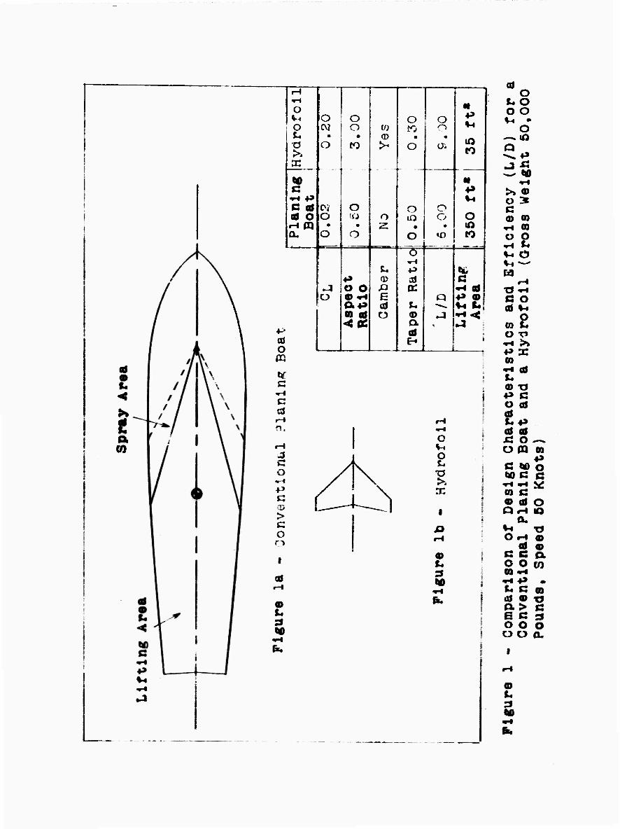
COMPARISON OF A CONVENTIONAL PLANING BOAT WITH A HYDROFOIL
Figure 1 gives the characteristics of a representative conventional
planing boat which was designed for a gross weight of 50,000 lb and a
speed of 50 knots. Also shown, to the same scale, is a hydrofoil designed
to carry the same gross weight at the same speed. A noteworthy contrast
between the two craft is the large disparity in the sizes of their lifting
areas. The lifting area of the planing boat (i.e., the area wetted by solid
water in plan view) is ten times as large as the lifting area of the hydro-
foil. Therefore the planing boat has the disadvantage of much higher fric-
tional resistance than the hydrofoil. The relationship between the lifting
areas is also reflected by the respective values of lift coefficient; i.e.,
the value of lift coefficient for the planing boat is l/lO the value for the W
hydrofoil. (CT here equals 5- , where ¥ Is 50,000 lb, and S Is the L />/2 Sv
lifting area in plan view; since Pfe equals 1.00 for salt water, this
simplifies to CT = —5 )• It is clearly important in connection with L Sv2
lifting efficiency, or lift-drag ratio, that the aspect ratio of the
hydrofoil is six times as large as the aspect ratio of the planing boat,
and that the hydrofoil has a carefully designed camber whereas the planing
boat has no camber.
In summary then, the planing hull differs markedly from the hydrofoil
in the values of three of the parameters - lift coefficient, aspect ratio,
and camber - which are of particular importance In connection with the
efficient attainment of dynamic lift. Furthermore, the hydrofoil was
designed with particular attention to those factors, while the design pro-
cedure for the planing hull ordinarily negjLects such considerations. It is,
therefore, not surprising that the lift-drag ratio for the hydrofoil
(including its associated strut and nacelle) Is 50 percent higher than
the lift-drag ratio for the planing hull. It is also evident that a
promising approach for improving the planing hull would be to design it
fron the point of view of the efficient attainment of dynamic lift.
-2-

LDT-DRAG RATIO VERSUS LDT COEFFICIEMT FOR A HYDROFOIL
One of the significant relationships vhich guides the design of an
efficient hydrofoil is that between lift-drag ratio and lift coefficient.
Such a relationship is shown in figure 2 for a representative foil-strut-
nacelle configuration. This figure Indicates that the maximum lift-drag
ratio attainable for this configuration is approximately 9*5 and that the
corresponding lift coefficient is 0.24. To avoid cavitation at the design
speed of 50 knots, however, it is necessary to reduce the design lift
coefficient to a value of 0.20. The lift-drag ratio will then be equal
to 9«0> which is the value indicated in Figure 1. If the value of the
design lift coefficient were reduced to 0.10 (corresponding to a doubling
of the foil area), the lift-drag ratio would drop to a value of 5»3- In
other words, the lifting efficiency would be reduced by about hO percent.
EFFEKTS OF LIFT OOEFFICIENT AHD ASPECT RATIO ON THE PERFOIMANCE OF PLANING HüUß
The relationship between lift-drag ratio and lift coefficient is of
primary importance for planing hulls as well as for hydrofoils. This
relationship can be determined for planing hulls by means of equations for
planing lift and drag, which have been developed by the NACA and the David
Taylor Model Basin, and subsequently programmed for solution by electronic *
computers. These equations are discussed in Reference 1. The resistance
equation has been revised for the present report to include the effect of
the spray area deflectors described in Reference 2. These deflectors give
a reduction in drag. Computed values of lift and drag for planing hulls
having 12.5-deg deadrise angle are plotted in Figure 5 in the form of
lift-drag ratio versus lift coefficient. Carves are shown for several
values of aspect ratio. It can be seen that for a particular value of
aspect ratio the relationship between lift-drag ratio and lift coefficient
for a planing hull is similar to that for a hydrofoil; i.e., the curve is
concave downward so that an optimum lift-drag ratio can be obtained by
appropriate selection of the lift coefficient.
References are listed on page f.

The highest values of lift-drag ratio for the various values of
aspect ratio (see Figure 5) have been plotted in Figure k to give a curve
of maximum L/D versus aspect ratio. It can be seen that the maximum L/D
improves markedly as the aspect ratio is increased from 0.5 to 2.0 but
that there is only a slight further improvement in efficiency with further
increase in aspect ratio. Also, an aspect ratio of 2.0, together with the
associated optimum value of lift coefficient of O.O575 (Figure 5), will give
a lift-drag ratio of 8.?. This is only slightly less than the value for the
hydrofoil, and represents a substantial improvement in performance over that
of the conventional planing boat shown in Figure 1. The conventional plan-
ing boat, with an aspect ratio of 0.5 and a lift coefficient of 0.02, is
operating at point "A" in Figure 3» Accordingly, as pointed our previously,
its lift-drag ratio is 6.0.
PROCEDURE FOR DESKaUNG AH EFFICIEKP LIFTING SURFACE FOR A PLANIHG BOAT
A method of selecting appropriate values of aspect ratio and lift
coefficient for an efficient planing surface is suggested above. The
remaining steps in a procedure for designing an efficient lifting surface
for a planing hull are as follows:
Knowing the value of the aspect ratio (assumed equal to 2.0 as discussed
above) and the corresponding value of optimum lift coefficient (equal to
0.0575)* the angle of attack 0C can be determined from Figure 5 to be
3.65 deg.
then
Also, since
r - W
s w
V' Next, since
-4
^000 = ^ ^2
O.0575 (50 • 1.688r
-u-

where A is the aspect ratio and b is the span of the lifting surface, then
b = v^s" = /2(122) = 15.6 ft
Also, since
A = b/A
where Ji is the mean length (or mean geometric chord) of the lifting m
surface, then
jg = b/A = 15.6/2 = 7-8 ft
The ratio It /j? can be read from Figure 6 to be equal to 0.841 cp' m
(jtf is the distance of the center of pressure, or center of gravity, cp
forward of the trailing edge of the lifting surface). Then
J2 = 0.841 (7-8 ft) = 6.6 ft
Knowing the dimensions J? and JL makes it possible to lay off the mean m cp
geometric chord of the lifting surface, as shown in Figure 9« The location
of the mean geometric chord will be at a distance b/4 outboard of the center-
line of the boat.
"Y (the angle of the stagnation line with the centerline in plan view)
is determined from Figure 7 to be equal to 2k deg, and 6 (the angle of the
spray direction with the centerline in plan view) is determined from
Figure 8 to be equal to 47-5 deg. Equations for determining the values of
•y and 6 were obtained fron Reference 5«
The dimensions and angles which have been derived make it possible to
lay out most of the details of the lifting surface shown in Figure 9. To
define the trailing edge of the lifting surface, however, it is necessary
to assume a value for the taper ratio (ratio of tip chord to root chord).
Analogy with the design of airplane wings and hydrofoils suggests that a
taper ratio of about 0.5 would be suitable (see, for example. Figure 1.^5
in Reference k). This value has accordingly been utilized and thus it is
possible to complete the plan view drawing of the lifting surface. A step
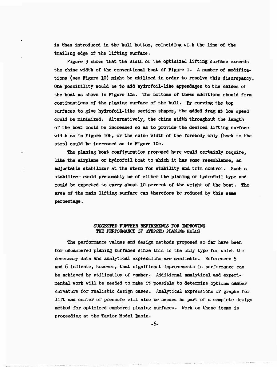
is then introduced in the hull bottom, coinciding vith the line of the
trailing edge of the lifting surface.
Figure 9 shows that the vidth of the optimized lifting surface exceeds
the chine width of the conventional boat öf Figure 1. A number of modifica-
tions (see Figure 10) might be utilized in order to resolve this discrepancy.
One possibility would be to add hydrofoil-like appendages to the chines of
the boat as shown in Figure 10a. The bottoms of these additions should form
continuations of the planing surface of the hull. By curving the top
surfaces to give hydrofoil-like section shapes, the added drag at low speed
could be minimized. Alternatively, the chine width throughout the length
of the boat could be increased so as to provide the desired lifting surface
width as in Figure 10b, or the chine width of the forebody only (back to the
step) could be increased as in Figure 10c.
The planing boat configuration proposed here would certainly require,
like the airplane or hydrofoil boat to which it has some resemblance, an
adjustable stabilizer at the stem for stability and trim control. Such a
stabilizer could presumably be of either the planing or hydrofoil type and
could be expected to carry about 10 percent of the weight of the boat. The
area of the main lifting surface can therefore be reduced by this same
percentage.
SUGGESTED FURTHER REFINEMENTS FOR IMPROVING THE PERFORMANCE OF STEPPED PLANING HULLS
The performance values and design methods proposed so far have been
for uncambered planing surfaces since this is the only type for which the
necessary data and analytical expressions are available. References 5
and 6 indicate, however, that significant improvements in performance can
be achieved by utilization of camber. Additional analytical and experi-
mental work will be needed to make it possible to determine optimum camber
curvature for realistic design cases. Analytical expressions or graphs for
lift and center of pressure will also be needed as part of a complete design
method for optimized cambered planing surfaces. Work on these items is
proceeding at the Taylor Model Basin.
-6-

Additional refinements can be incorporated into planing lifting sur-
faces which will lead to further improvements in performance. Reference 7
indicates that the utilization of either horizontal chine flare or vertical
chine strips (i.e., end plates) will increase the lift-drag ratio of a
planing surface by more than 15 percent. Reference 8 indicates that such
small end plates will also effectively suppress the main spray blister
created by a planing surface. A number of the foregoing factors taken
together suggest that the type of optimized higjh-aspect-ratio, cambered
lifting surface proposed here, when fitted with the end plates just
referred to, would probably give a planing boat tne desirable characteristic
of making only a small surface disturbance and would, therefore, make it
suitable for running at high speed in restricted waters.
REFERENCES
1. Clement, E. P. and Pope, J.D., LTJG, USN, "Stepless and Stepped
Planing Hulls - Graphs for Performance Prediction and Design," David Taylor
Model Basin Report 1^90 (Jan 1961).
2. Clement, E. P., "Effects of Longitudinal Bottom Spray Strips on
Planing Boat Resistance," David Taylor Model Basin Report l8l8 (Feb 1964).
5. Savitsky, D., "Hydrodynamic Design of Planing Hulls," Davidson
Laboratory Report 1000 (Dec 1965).
k. Milliken, C. B., "Aerodynamics of the Airplane," John Wiley and
Sons, Inc. (19^1).
5. Sottorf, W., "Experiments with Planing Surfaces," NACA TM 759
(Mar 195^).
6. Tulin, M. P., "The Theory of Slender Surfaces Planing at High
Speeds," Schiffstechnik, Band k (1956/1957), Heft 21, pp. 125-155.
7. Kapryan, W. J. and Boyd, G. M., Jr., "The Effect cf Vertical Chine
Strips on the Fleming Characteristics of V-Shaped Prismatic Surfaces
Having Angles of Dead Rise of 20° and 40°," NACA TN 5052 (Kov 1955).
8. Savitsky, D. and Breslin, J. P., "On the Main Spray Generated by
Planing Surfaces," SMF Fund Paper No. FF-lB, Institute of the Aeronautical
Sciences (Jan 1958).
I
•*
c
I
TJ OO O O O C 3 3 3 <tJ CX <p p W 3 T • tf »*
•-* CO woo
2 B 9 *-* O O. »-%
•O Oi !-• O O P <D
3 3WI O OH 3
a» to o — O 3 (B p
(B P O 3 e* a ©
CO X ct
%x o gco
•-* a» O 3 M. p.
m o -* o o (0 M- CO CD
3 C O a> «< »-*
* c: o
o • •-* o o O 1 o to
0»» ß CD
i
<
O
o ^7
OH C »1
I
tJ o <
c+
O
r *->
'ü
A
tu •
| H ! s P ct \
t* » •o »► \ >•- tr CD o p u \ 1 ** "^^ T p et-O \ 0 ct o 3 ►* P o > P M. 31 a o o tr
9 P? 0) et Ä T
0) — ■—|
O O o 'Ü Oi • • 2 • • to •-' o O CP o rn o O P
o C o !0 P 3 •-% Ct M- c» 3 N 9)
X 09 '.O o ►< OI Ü %^" • • CD • • ^ »-k • o 03 W o ro o i ct O O o o •-* M o
I ! 1 »-•

10
8
o j
0
^ ^" N
> if
\
/ >
L
t
r \
; \
/ \
/
/
/
/
r
/
/
;
f •
i
.. o n.'ir ;t r •atio • ■
1
'K —i
{ i !
«3 —1
I ) i
i
i
Ü 0.1 0.2 0.3
Figure 2 - Lift-Drag Ratio versus Lift Coefficient for a Typical Hydrofoil-Strut-Nacelle Configuration

10
2.
0-
!
■^ < ^
J ^ v N, /
s N \ s
/^
i N s^ S
\
f r
\ S \
V N ^ k
jk i N \
...^
\ N. ^spi ct *
i N .5 1
i. 0 *•
1
:
1 i i ! 1 1
i f 1
1
j
i I 1
1 ! i « 1 i « :
i
i
f
i 1 ; ! !
!
_3.0
0.02 0.10 0.12 0.04 0.06 0.08
Figure 3 - Lift-Drag Ratio versus Lift Coefflcent for Planing Hulls of Various Aspect Ratios (12.6 Degree Deadrise, 0.0004 ACf)
0.14

Hull L/D
6
3
ß P
< r* 9 *•
•
>
• o Jo •< ?
• €• ci »* • « o m c a« 2L» M 01 • TJ
• P O 9 €* P.
9 OP • c» o»- oo o *** . o ^T ci
Hk 1» H» p a »■*
9 O«J
u
» • <* m « o i i i 1 1 i t
! l i • I J 1 1 1
f I N t i ! \
1 i i
i ■ —
' x
i \ 1 1 1 Mil' —
! 1 i ■ 1 1 I i ' 1% ' ■ i" " ' :! ä I
\ ! i i • ■'
1 \l | !
i \l i 1 i.
1 1 1 1 1 1 t i ! | 1 1 i
a \ i
" ! 1 1 1
1
i i
1 1 1
| _
\
-—*———

oat
o.io
o.o»
3 4 a In degrees
figure 5 - Lift Coefficient versus Angle of Attack for Planing Hulls of Various Aspect Ratios. (12.5 Degree Oeadrlse)

o.vo
e
T 4 a In degrees
Figure 6 - Center-of-Pressure/Mean-Wetted-Length Ratio versus Angle of Attack for Planing Hulls cf Various Aspect Ratios (12.5 Degree Deadrise)

0 6
a in degrees
Figure 7 - Angle'K between Stagnation Line and Ceaterllne In Plan View.

0 z
Figure 8
4 6 8 a In degrees
Angle e between Spray Direction and Centerline In Plan View.

c 1
wo *a "öl H- 0)0 |D ® C0 3 a at
<
^* c 9* tr o
O fD
o ►* Oi O 3 OO (*
I i
o
n
o
vn
S All a o o c e* 3 i- co a
OB c »-* et er o
(0 <D B
«a N O »1 <D
CO 50 ® t- (D M. rf !-• H»
O • Hk
« a
C2? K'fc' c+o a: r. m P is » pi
3 3 M
o 3
309
3 O 3 p
32 5»
« a
09 O
tlJ. /
/
T B
3 o MO O
• O IB l*
S« Ü <♦ ft O 3
2 Q tt »s o C • 3 C *4 *l 2. »I © ft H
§ S ST? ° 8
«
I* 3
rr I* O 3
3" CI- ST
ct- 3 O
Ü1 <D
to a>
^^(o
B (A
W c
SB o
O
3 ct
O •
3 M O- »* ft 3 »1 «
■T
ro
M Kb «■ •-» C cr ** H-
o a
»i IB O. O
o
^ ^ VA < • • • 0 0
s 00 Ov !-•
»^ »^ ^ § c* ct- ct-

Figure 10A - Local Extensions Added to Planin« Bottoi (Plat on Botto« and Curved on Top)
-V i
x > y"
'l«ure lob - chine width Increased throughout Hull Length
Figure 10c - Chine width T«* ne Wldth Increased Baclc to step
rieUn l0 - tinX^'V™™ - —"• ". sp.01nM

MITIAL DISTKEBOTIÖH
Copies 15 CHBUSHIPS
3 Tech Lib (Code 210-L) 1 Lab Mgt Div (Code 520) 1 App Res Div (Code iko) 2 Prelim Des (Code 1*20) 2 Hull Des (Code hkO) 2 Sei & Res (Code kk2) k Boats & Small Craft (Code U9)
1 COMOT, U.S. Coast Guard
2 00, U.S. Army Transportation Research Ccnmand, Fort Bust is 1 Attention Tech Intelligence Br 1 Attention Mr. Richard W. Black
2 DIR, Davidson Lab, SIT, Hoboken
2 AIMI», Webb Inst of Naval Arch, Glen Cove Attention Prof. Thomas M. Curran
2 Head, Dept of NAME, MIT, Cambridge
2 Head, Dept of N/ME, Univ of Michigan, Ann Arbor
2 Aerojet-General Corporation, Washington Attention Mr. A. Marke1
1 Aircraft Armaments Inc., Cockeysville, Md.
1 AVCO Corp., Wilmington Attention Capt. F. X. Forest
1 DIR, Hudson Lab, Dobbs Feriy
1 Fluid Dynamics Research Lab, Collins Radio Co., Cedar Rapids
1 Sparkman and Stephans, Inc., New York Attention Mr. G. Gilbert Wyland
1 Bell Aerosystems Co., Buffalo, New York
1 Boeing Airplane Co., Seattle
2 Chris-Craft Corp., Pompano Beach Attention Mr. E. L. Eckfield
18

2 Gibbs and Cox, Inc.
1 General Dynamics/convair, San Diego Attention Mr. R. H. Oversmith
2 Grumman Aircraft Eng Corp
2 Hydronautics, Inc
2 Lockheed-California Co., Burbank
1 Republic Aviation Corp., Farmingdale Attention Mr. Joseph G. Koelbel, Jr.
1 Owens Yacht Division, Brunswick Corp Attention Mr. David D. Beach
1 United Aircraft Corporate Systems Center, Farmington, Conn. Attention Mr. Henry A. Arnold
1 Cdr. E. Vanning Jr., USN Ojarters- "P" Norfolk Naval Shipyard, Portsmouth
20 DDC
19

T'S -sT - 5 « 9
* -^ ' m » ■ *E *■• &•
y = = - 5 2 * "t.
w-s.t 9
ill-I J| 2 5 * £ 5. "= x 1
5 f 5 S » f =
!-
*._;—• «.- 5
rl^s fa? a. _ a s — ~ ^
SV
2 ei Jl ^ ^ » S 3 ' $
is ?e --i
it'll
£.2 - » i - • » 5 » ■9 •* _ - S
1 li »1
» a- S S »
a y3i 1 lit
» - ^ ^
— *
Mr »si •9 X —
m — r
3 ^ —^ *• • *
$ = =
-5 ■•i T» 3 a s « 3" 5"
i? ?
r s-s»
I I f 2 3 3 3 H ■
«r r HI? i
Hi ? m 5 -
— ' r* y t C 3 ' » * - C 3 S 3 » 2 _ o ■
iSSsi • _ 3 -•
^| - S 3
1 3 3 F
» a. r S 2,
3§>? •a at.* «
TSC-
-
.ill ' y**
— . 9 •S J» • 3 •«
"^ x_.
— - 2 ** ~s j*
?:E = X c B
s?c !■»- >
er. ft- Mi is »■ i
5 5'
5 e
a s 3 _
£ ?^«ä-S■ O 3 1. X *.
J« 3 3 3
? M ^ 3-| 3 3 » 3" 3-
Si5 s* £. _- 5" - » * •» r-s.
»g «_ ■
5 * |. S 3 og ,=-
•a. »>i
«,
< aeS"
3?
SI- A 2 *♦
-•«2.
II
■» x_.
j^ «e «>*
> z g = Ä
s: >
T "flö "fl » S"
3 • 3 3 3
3 3 3
I f l 3 .■ •
"0 * 3
O •So "fl
nil
9 c 3