within slab installation radiant heat
TRANSCRIPT

8/6/2019 Within Slab Installation Radiant Heat
http://slidepdf.com/reader/full/within-slab-installation-radiant-heat 1/7
All connections are made at
the manifold. No connec-
tions should be cast into the
concrete. The entire mani-
fold, including the plywood
box, is cast into the floor.
The plywood box serves to
protect the manifold duringconstruction and it also
serves as a concrete form.
The box can be knocked
completely apart after the
concrete has set. The mani-
fold now sets in a hole in the
floor (called a manifold well).
Plan The Installation—Make a layout and decide how
many circuits you should have in
each zone based upon minimum
and maximum circuit lengths.
(Radiantec can help you in person
or over the telephone, 1-800-451-
7593). Refer to your worksheet
and underfloor material calculations
provided with your price quote.
Slab InsulationFor maximum performance and efficiency, the slab should be insulated from the earth.
Refer to Radiantec’s Design & Construction Suggestions. For layout hints, refer to
Radiantec’s Layout Supplement.
Install the Tubing for a “Slab on Grade” Project—
Radiantec projects will use a “slab manifold”. The manifold is the place where themain copper pipe that comes from the heater connects to one or more circuits of
plastic tubing.
Adaptors and fittings Plywood box
Pressure testing
equipment
Individual shut off valves
1
W I T H I N S L A B I N S TA L L AT I ON
Radiantec I N S TA L L AT I S U P P L E M E N
250
Slabs

8/6/2019 Within Slab Installation Radiant Heat
http://slidepdf.com/reader/full/within-slab-installation-radiant-heat 2/7
The plastic tubing does not come out of the floor where it could be damaged.
Concrete does not come in contact with the copper manifold which would cause cor-
rosion. Access to the fittings is preserved if necessary. If you want to conceal the
manifold, fill the hole with sand and lay a skim coat of mortar over it. When the
pressure testing equipment is removed, two pipes (one supply, one return) is all that
is visible. Arrange for a partition to fall over these two pipes. You can also locate the
manifold in a place where it will not be seen, such as a closet. Manifolds are avail-
able in custom configurations with no extra charge.
Lay Out the Reinforcing Steel
The heating system will perform better, and will be easier to install if some steel is
placed both above and below the tubing. The slab will be very strong in the vicinity
of the tubing and the steel will help to distribute the heat away from the tubing more
effectively. Steel below the tubing gives the installer something to tie the tubing to.
Steel above makes the tubing less likely to float to the surface and guards against
potential damage from the power trowel.
The following procedure works well for many slabs and can be modified to suit
different structural needs.
1. Find the type of bricks with three holes in them
and bust them into four pieces at the holes.
2. Lay out a grid with reinforcing rod spaced four
feet apart. Hold the rod up with the brick pieces.
3. Lay out the tubing and tie it to the rerod.
4. Lay out another grid of reinforcing rod spaced
four feet apart but offset two feet so that the
bird’s eye view would be of a grid with two footspacing (see below).
5. Instead of bricks, other alternatives are available to hold up your rerod,
such as chairs, pieces of leftover insulation, or blocks of wood.
6. The tubing may also be sandwiched between two sheets of wire mesh.
The first layer of reinforcing steel The second layer of reinforcing steel

8/6/2019 Within Slab Installation Radiant Heat
http://slidepdf.com/reader/full/within-slab-installation-radiant-heat 3/7
8/6/2019 Within Slab Installation Radiant Heat
http://slidepdf.com/reader/full/within-slab-installation-radiant-heat 4/7
Use multiple parallel circuits instead of just one long one. Refer to and comply with
maximum circuit lengths for the tubing that you are working with. Multiple circuits
require less pump work and the fluid will not cool off too much. Because additional cir-
cuits run parallel to the first, they will be easy to do once the first circuit is in place and
arranged properly. An exact tubing arrangement is not required.
The important points are:
1. Put in the linear amount of tubing that is required.
2. Space out the tubing reasonably well.
3. Do not kink the tubing.
Absolute precision is usually not very important. An exact and perfect arrangement is a
waste of time and can also waste tubing. It is acceptable if the tubes cross one another
as long as the concrete has adequate thickness.
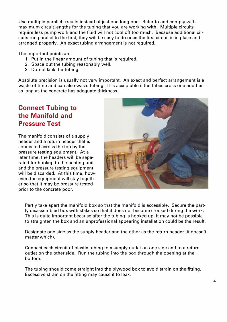
Connect Tubing to
the Manifold and
Pressure Test
The manifold consists of a supply
header and a return header that is
connected across the top by the
pressure testing equipment. At a
later time, the headers will be sepa-
rated for hookup to the heating unit
and the pressure testing equipmentwill be discarded. At this time, how-
ever, the equipment will stay togeth-
er so that it may be pressure tested
prior to the concrete poor.
Partly take apart the manifold box so that the manifold is accessible. Secure the part-
ly disassembled box with stakes so that it does not become crooked during the work.
This is quite important because after the tubing is hooked up, it may not be possible
to straighten the box and an unprofessional appearing installation could be the result.
Designate one side as the supply header and the other as the return header (it doesn’t
matter which).
Connect each circuit of plastic tubing to a supply outlet on one side and to a return
outlet on the other side. Run the tubing into the box through the opening at the
bottom.
The tubing should come straight into the plywood box to avoid strain on the fitting.
Excessive strain on the fitting may cause it to leak.

8/6/2019 Within Slab Installation Radiant Heat
http://slidepdf.com/reader/full/within-slab-installation-radiant-heat 5/7
To make the connection with 7/8”
tubing, first slip the vinyl sleeve and
stainless steel clamps over the end
of the plastic tubing. Warm the tub-
ing with a heat gun or boiling water
to slightly soften it. Some workers
will very carefully use a torch but
we cannot recommend the practice.
Push the warmed plastic end onto
the insert adaptor all the way to the
shoulder of the fitting.
Bring the vinyl sleeve and the stain-
less steel clamps back down the
plastic pipe to the serrated part of
the adaptor and screw the clampdown tightly with the vinyl sleeve
acting as a cushion.
Double clamp the fitting for an extra
strong connection. Plan the connec-
tion so that the hubs are opposite
each other.
If a coupling is used, be sure to
double clamp each end and be sure
to use the vinyl sleeve so that con-crete does not come in contact with
the brass fittings.
In general, fittings should not be
cast into concrete, but if absolutely
necessary, these fittings are very
reliable.
Do all soldering first. Do not solder
close to the plastic fitting.
Coupling for 7/8” tubing
Adaptors for 7/8” tubing

8/6/2019 Within Slab Installation Radiant Heat
http://slidepdf.com/reader/full/within-slab-installation-radiant-heat 6/7
3. When you’re ready to hook up your system, the pressure testing equipment can be
taken off by applying heat to the elbows. One elbow is the air vent and the other has
the air stem.
Suspended SlabsWhen tubing is installed in suspended slabs or topping slabs, the process is very similar
to that of a slab on grade. However, these slabs tend to be thinner, and reinforcing and-
placement of reinforcing steel is more important. There should be a minimum of 1 inch
of concrete covering the tubes.
Lay the tubing out and secure temporarily with duct tape, or something similar. Then
place reinforcing mesh over the tubing and secure well with concrete nails if over a
concrete sub-base, or wide head roofing nails if over plywood.
Slide the locking nut and split
compression ring up the tubing.
Insert the tubing onto the
compression fitting.
Tighten the nut onto the
compression fitting snugly.
Compression coupling fittings should
be isolated from the concrete with
electrical tape or equivalent.
1. Charge with air to 50 psi. Wait
two hours. There should be no
loss of pressure.
2. Use newspapers or rags to seal
off the area of the box where the
tubes enter so that concrete will
not enter the box.
When using 1/2inch PEX tubing, the fittings will be of the compression type.
Adaptor for 1/2” PEX
Coupling for 1/2” PEX
Pressure t
the work
before you
pour the
concrete.
Pressure Test

8/6/2019 Within Slab Installation Radiant Heat
http://slidepdf.com/reader/full/within-slab-installation-radiant-heat 7/7
Tool List
1. Phillips and flathead screwdrivers.
2. 5/16” nut driver (optional).
3. Hacksaw (to cut the tubing).
4. Long tape measure.
5. Air compressor with “tire” type adaptor (for the pressure test).
6. Adjustable wrench.
7. Heat gun.
8. C clamps, screws, etc. to secure the manifold
Important notice - These design and installation suggestions are of a general nature and they are
based upon our 25 years of experience. It is important to understand that every project is a little differ-
ent. It is the role of the designer to incorporate all available information into the project. Radiantec makes
no representation that these general suggestions are applicable to any particular project. Radiantec takes
no responsibility for the design of any heating project. Radiantec makes no representation about the
completeness of the information provided. It is important to comply with all building codes.
Copyright 2003, Robert J. Starr
Revised on
1/18/04