weil mclain radiant heat
DESCRIPTION
Radiant heat design guideTRANSCRIPT
Design GuideDesign GuideDesign GuideDesign GuideDesign Guide
AlumiPAlumiPAlumiPAlumiPAlumiPeeeeexxxxx®®®®®
RRRRRadiant Tadiant Tadiant Tadiant Tadiant Tubingubingubingubingubing
Controls ● Pumps ● Wiring
Part No. 650-000-240/1098
Part Number 650-000-240/10982
AlumiPAlumiPAlumiPAlumiPAlumiPeeeeexxxxx® ® ® ® ® Radiant TRadiant TRadiant TRadiant TRadiant Tubingubingubingubingubing
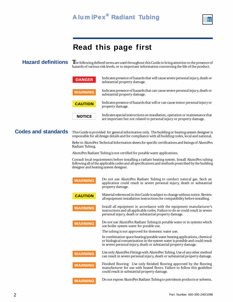
The following defined terms are used throughout this Guide to bring attention to the presence ofhazards of various risk levels, or to important information concerning the life of the product.
Read this page first
This Guide is provided for general information only. The building or heating system designer isresponsible for all design details and for compliance with all building codes, local and national.
Refer to AlumiPex Technical Information sheets for specific certifications and listings of AlumiPexRadiant Tubing.
AlumiPex Radiant Tubing is not certified for potable water applications.
Consult local requirements before installing a radiant heating system. Install AlumiPex tubingfollowing all of the applicable codes and all specifications and methods prescribed by the buildingdesigner and heating system designer.
Indicates special instructions on installation, operation or maintenance thatare important but not related to personal injury or property damage.
Indicates presence of hazards that will or can cause minor personal injury orproperty damage.
Indicates presence of hazards that can cause severe personal injury, death orsubstantial property damage.
Indicates presence of hazards that will cause severe personal injury, death orsubstantial property damage.
Do not expose AlumiPex Radiant Tubing to petroleum products or solvents.
Finished flooring: Use only finished flooring approved by the flooringmanufacturer for use with heated floors. Failure to follow this guidelinecould result in substantial property damage.
Use only AlumiPex Fittings with AlumiPex Tubing. Use of any other methodcan result in severe personal injury, death or substantial property damage.
Do not use AlumiPex Radiant Tubing in potable water or in systems whichuse boiler system water for potable use.
The tubing is not approved for domestic water use.
In combination space heating/potable water heating applications, chemicalor biological contamination in the system water is possible and could resultin severe personal injury, death or substantial property damage.
Install all equipment in accordance with the equipment manufacturer’sinstructions and all applicable codes. Failure to do so could result in severepersonal injury, death or substantial property damage.
Hazard definitions
Codes and standards
Do not use AlumiPex Radiant Tubing to conduct natural gas. Such anapplication could result in severe personal injury, death or substantialproperty damage.
Material referenced in this Guide is subject to change without notice. Reviewall equipment installation instructions for compatibility before installing.
Part Number 650-000-240/1098 3
Controls ● Pumps ● Wiring — Installation Guide
Contents
I Overview .................................................................................................................................. 4
II Piping & control methodsThree temperature control ...................................................................................................... ..................................................... 5Exceptions .................................................................................................................................................................................... 6Piping/ controlling methods ......................................................................................................................................................... 6Method 1 - Variable speed injection mixing ............................................................................................................................... 7Method 2 - Dual three-way valves .............................................................................................................................................. 9
III Primary/secondary pipingWhy use primary/secondary piping? ........................................................................................................................................ 10Primary/secondary piping tips ................................................................................................................................................... 12
IV Zoning radiant heating systemsCombining spaces for zoning ..................................................................................................................................................... 15Using zone valves and/or valve actuators ................................................................................................................................ 15Combining circuits on manifolds ............................................................................................................................................... 16Control circuit transformer sizing ............................................................................................................................................... 16
V Control strategies – generalOutdoor reset .............................................................................................................................................................................. 20Constant circulation .................................................................................................................................................................... 21
VI Injection mixing componentsWeil-McLain IPC Injection Pump Control ................................................................................................................................... 22Weil-McLain IPP-150 Injection Pump Panel .............................................................................................................................. 24
VII Determining flow ratesPrimary circuit flow rate ............................................................................................................................................................. 26Injection pump flow rates .......................................................................................................................................................... 30Secondary circuit flow rates ...................................................................................................................................................... 31
VIII Determining head lossEquivalent length .............................................................................................................. .......................................................... 32Head loss (series circuits) .................................................................................................... ...................................................... 32Determining head losses for circuits in parallel ............................................................................... ......................................... 35Head losses for AlumiPex tubing circuits ....................................................................................... .......................................... 36
IX Selecting pumpsMethod 1 - select pump from pump curve ............................................................................................................................... 39Method 2 - select pump from quick selector curves ................................................................................................................ 41
X Piping radiant circuits ........................................................................................................... 46
XI Domestic water heating ....................................................................................................... 52
XII Radiant heating system examples ...................................................................................... 54System CP-1 Adding a small zone of radiant heating to an existing baseboard heating system........................................................................................................... 56SystemC P-2 GV boiler supplying an injection pump panel ................................................................................................................................................................. 60SystemC P-3 Conventional boiler supplying an injection pump panel .................................................................................................................................................. 64SystemC P-4 Two-temperature radiant heating system using two injection pump panels ................................................................................................................... 68System CP-5 Two-temperature radiant heating system using one injection pump panel and a mixing valve ...................................................................................... 72SystemC P-6 Radiant heating and domestic water heating with conventional boiler - DHW as a secondary circuit ............................................................................ 76SystemC P-7 Radiant heating and domestic water heating with GV boiler - DHW as a secondary circuit ............................................................................................ 80SystemC P-8 Radiant heating and domestic water heating with conventional boiler - independent DHW operation ........................................................................... 84System CP-9 Radiant heating and domestic water heating with GV boiler - DHW through diverting valve.......................................................................................... 88System CP-10 Radiant heating, domestic water heating and baseboard heating with conventional boiler ............................................................................................ 92System CP-11 Radiant heating, domestic water heating and baseboard heating with GV boiler ........................................................................................................... 98System CP-12 Radiant heating, domestic water heating and baseboard heating with multiple boilers ................................................................................................ 104
XIII Appendix .............................................................................................................................. 110
Part Number 650-000-240/10984
AlumiPAlumiPAlumiPAlumiPAlumiPeeeeexxxxx® ® ® ® ® Radiant TRadiant TRadiant TRadiant TRadiant Tubingubingubingubingubing
What’s in this guide?
I Overview
We intend this Guide to provide system designers withthe information needed to select and specify controls,pumps and piping for AlumiPex radiant heating systems.
The most important message in thisguide is the need to control not justspace and supply water tempera-tures, but to design and installsystems that regulate the boilerreturn water temperature.
Piping & control methods provides you a choice oftwo basic piping/control designs which meet the needsof AlumiPex® radiant heating systems and the needs ofnoncondensing boilers. These are —
• Variable speed injection mixing (preferred method)
• Dual three-way valves (alternate method)
Though other designs can accomplish similarperformance, we have chosen to concentrate on a limitedselection to assure coverage in depth.
Primary/secondary piping outlines the reasons for usingprimary/secondary piping and some suggestions on howto apply it.
Zoning radiant heating systems provides guidelinesfor combining spaces in zoning and how to applyAlumiPex zoning components.
Control strategies – general presents the case foroutdoor reset and discusses continuous (or extended)circulation in radiant heating, along with some guidelinesfor setting up reset controls.
Injection mixing components gives a brief introductionto the Weil-McLain Injection Pump Control, the IPC,and the Injection Pump Panel, the IPP. For furtherinformation on these components, refer to the InjectionPump Panel/Injection Pump Control (IPC) Installationand Operating Manual.
Determining flow rates provides suggestions on howto calculate the flow rates needed for each type of circuitin a radiant system - for multiple purpose systems aswell as for radiant heating only.
Determining head loss provides means for calculatinghead losses in copper and steel piping and in AlumiPexradiant tubing circuits.
Selecting pumps provides pump curves for commonpumps. This section includes a new approach to pumpsizing - curves for ½”, ¾” and 1” AlumiPex tubing and ¾”through 2” copper piping that show pump GPM vssystem equivalent length for common circulators(pumps). This allows you to directly select a pump basedon your system equivalent length and flow rate, or to seewhat will happen if you place a different pump on yoursystem, without having to draw a system curve.
Piping radiant circuits and Domestic water heatingintroduce the final section of this guide, devoted to specificmethods for piping and controlling radiant systems andmultiple purpose systems (radiant heating plus domesticwater heating and baseboard heating). These sectionsprovide the background for the radiant heating pipingexamples which follow.
Radiant heating examples includes 12 examples ofradiant heating systems, including multiple purposesystems for domestic water and baseboard heating. Thesedo not represent all of the possibilities, but show someeffective applications of the principles discussed in thisGuide. Note, in particular, the emphasis on three-temperature control – control the boiler returnwater temperature (to protect the boiler) in additionto space and supply water temperatures.
This guide does not include radiant heating heat losscalculations or tubing placement design. These arehandled in separate publications. Weil-McLain currentlyprovides a computer-based sizing system — theAlumiPex Radiant Expert program. We recommendusing the A.R.E. in combination with this guide for themost comprehensive coverage of radiant heating designwith our products.
Part Number 650-000-240/1098 5
Controls ● Pumps ● Wiring — Installation Guide
Piping and control designs must not only regulate space comfort - they must also:• assure the correct water supply temperature to the heating system.• protect noncondensing boilers from flue gas condensation and thermal shock.
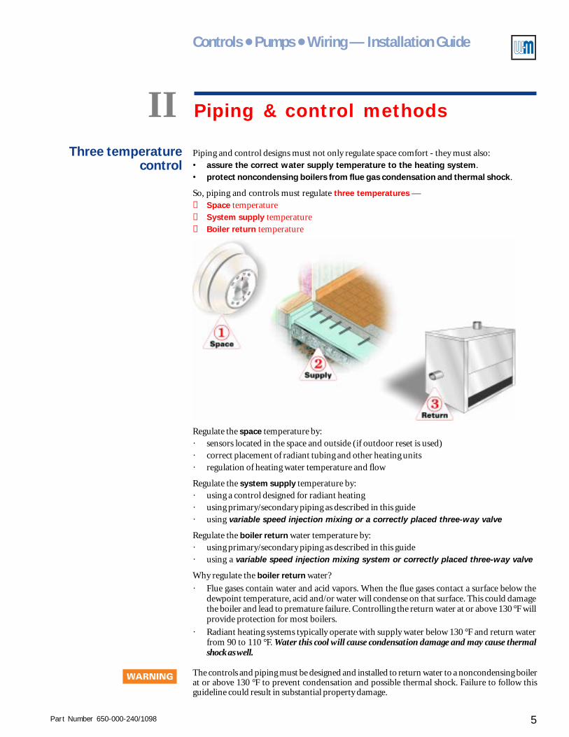
So, piping and controls must regulate three temperatures —① Space temperature② System supply temperature③ Boiler return temperature
Regulate the space temperature by:· sensors located in the space and outside (if outdoor reset is used)· correct placement of radiant tubing and other heating units· regulation of heating water temperature and flow
Regulate the system supply temperature by:· using a control designed for radiant heating· using primary/secondary piping as described in this guide· using variable speed injection mixing or a correctly placed three-way valve
Regulate the boiler return water temperature by:· using primary/secondary piping as described in this guide· using a variable speed injection mixing system or correctly placed three-way valve
Why regulate the boiler return water?
· Flue gases contain water and acid vapors. When the flue gases contact a surface below thedewpoint temperature, acid and/or water will condense on that surface. This could damagethe boiler and lead to premature failure. Controlling the return water at or above 130 °F willprovide protection for most boilers.
· Radiant heating systems typically operate with supply water below 130 °F and return waterfrom 90 to 110 °F. Water this cool will cause condensation damage and may cause thermalshock as well.
Three temperaturecontrol
II Piping & control methods
The controls and piping must be designed and installed to return water to a noncondensing boilerat or above 130 °F to prevent condensation and possible thermal shock. Failure to follow thisguideline could result in substantial property damage.
Part Number 650-000-240/10986
AlumiPAlumiPAlumiPAlumiPAlumiPeeeeexxxxx® ® ® ® ® Radiant TRadiant TRadiant TRadiant TRadiant Tubingubingubingubingubing
II Piping & control methods - continued
The most common heating source for radiant heatingsystems is a noncondensing boiler. The boiler may becast iron, steel or copper, but will usually require aminimum return water temperature, as specified by theboiler manufacturer. If the manufacturer states aminimum return temperature - regardless what thattemperature is - the piping and controls must assurethe water temperature does not return to the boiler belowthe minimum.
The risk of not controlling the temperature is damage tothe equipment - ranging from minor corrosion tocomplete failure of the heat exchanger.
Exceptions
There are exceptions to the need for return watertemperature control - but ONLY for cases where the returnwater temperature will naturally remain above theminimum specified by the boiler manufacturer.
An example is the special case of floor heating using tubingsuspended in the joist bays (not stapled to the floor). Forsuch systems, the supply water temperature is usually160 °F or higher. Moreover, the radiant system has lowmass because the tubing is not in contact with the floor.So, these systems will behave similarly to finned tubebaseboard systems - return water temperature will nearlyalways be above 130 °F, and any periods of lower returntemperature will be brief.
Such exceptions are not illustrated in this Guide (exceptfor System CP1, discussed below) to avoid confusing theissue. Most radiant heating installations requirereturn water control because most of the heatingsources require a minimum.
You will find an exception to regulated return temperaturein Radiant heating system examples, System CP1.This special case applies to a small radiant circuit addedto an existing baseboard heating system. For this situation,return water protection is unnecessary because the radiantcircuit will not reduce the return water temperaturesignificantly.
Piping/controlling methods
This Guide focuses on the two preferred methods ofregulating space, supply water and return watertemperatures -
Method 1 - Variable speed injection mixing.
Method 2 - Dual three-way mixing valves.
Method 2 may, in some cases, have a lower first cost thanMethod 1. But Method 2 cannot provide outdoor resetcontrol without motorized valves - this could causeMethod 2 to be more costly than Method 1.
Alternative piping/controllingmethods
This Guide addresses only these two methods in order toprovide coverage in depth. Other methods can be usedand are covered in supplementary documents.
No alternative is as effective or flexible, however, asMethod 1 - variable speed injection mixing. The Weil-McLain IPP Injection Pump Panel and IPC Injection PumpControl provide exceptional control and a wide range ofcontrol options.
Interchangeability
Figures 2 and 3 are simplified schematics of Methods 1and 2, respectively.
Note the piping contained in the dotted rectanglesof these schematics. Wherever an IPP Injection PumpPanel (Method 1) is shown in piping diagrams in thisGuide, you can substitute the piping in the dottedrectangle in Figure 3. That is, the dual three-way mixingvalves, piped as shown, will provide the same regulationand protection as Method 1.
Bear in mind, if outdoor reset is desired with Method 2,a motorized valve and appropriate controls will berequired.
Part Number 650-000-240/1098 7
Controls ● Pumps ● Wiring — Installation Guide
Method 1 — Variable speed injection mixing
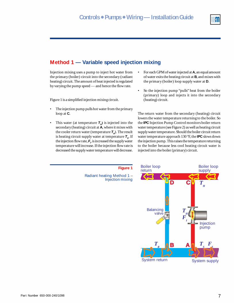
Injection mixing uses a pump to inject hot water fromthe primary (boiler) circuit into the secondary (radiantheating) circuit. The amount of heat injected is regulatedby varying the pump speed — and hence the flow rate.
Figure 1 is a simplified injection mixing circuit.
• The injection pump pulls hot water from the primaryloop at C.
• This water (at temperature TH) is injected into thesecondary (heating) circuit at A, where it mixes withthe cooler return water (temperature TR). The resultis heating circuit supply water at temperature TS. Ifthe injection flow rate, FI, is increased the supply watertemperature will increase. If the injection flow rate isdecreased the supply water temperature will decrease.
AA
CC TH
TH
FI
FS
TS
TR BB
DD
Boiler loopsupply
Boiler loopreturn
System supplySystem return
Injectionpump
Balancingvalve
Figure 1
Radiant heating Method 1 –Injection mixing
• For each GPM of water injected at A, an equal amountof water exits the heating circuit at B, and mixes withthe primary (boiler) loop supply water at D.
• So the injection pump “pulls” heat from the boiler(primary) loop and injects it into the secondary(heating) circuit.
The return water from the secondary (heating) circuitlowers the water temperature returning to the boiler. Sothe IPC Injection Pump Control monitors boiler returnwater temperature (see Figure 2) as well as heating circuitsupply water temperature. Should the boiler circuit returnwater temperature approach 130 °F, the IPC slows downthe injection pump. This raises the temperature returningto the boiler because less cool heating circuit water isinjected into the boiler (primary) circuit.
Part Number 650-000-240/10988
AlumiPAlumiPAlumiPAlumiPAlumiPeeeeexxxxx® ® ® ® ® Radiant TRadiant TRadiant TRadiant TRadiant Tubingubingubingubingubing
Method 1 — Variable speed injection mixing
II Piping & control methods - continued
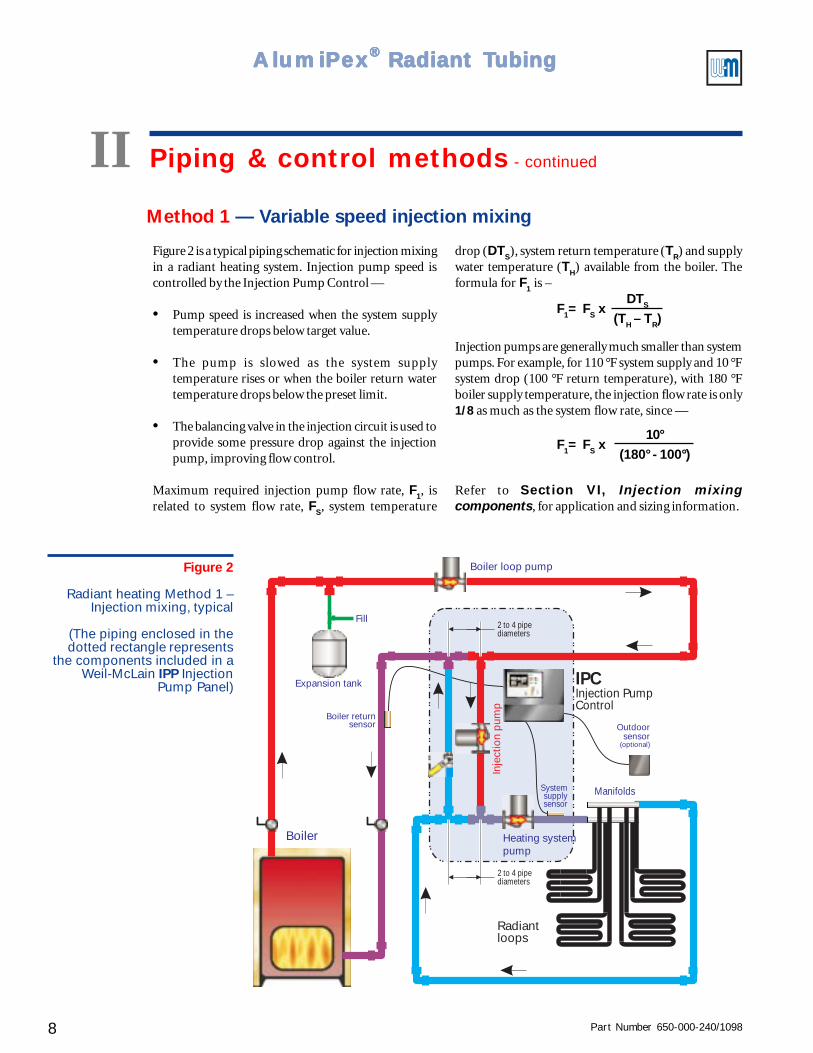
Figure 2
Radiant heating Method 1 –Injection mixing, typical
(The piping enclosed in thedotted rectangle represents
the components included in aWeil-McLain IPP Injection
Pump Panel)
Figure 2 is a typical piping schematic for injection mixingin a radiant heating system. Injection pump speed iscontrolled by the Injection Pump Control —
• Pump speed is increased when the system supplytemperature drops below target value.
• The pump is slowed as the system supplytemperature rises or when the boiler return watertemperature drops below the preset limit.
• The balancing valve in the injection circuit is used toprovide some pressure drop against the injectionpump, improving flow control.
Maximum required injection pump flow rate, F1, isrelated to system flow rate, FS, system temperature
Fill
Expansion tank IPCInjection PumpControl
Boiler
Boiler returnsensor
Boiler loop pump
Radiantloops
Manifolds
Inje
ctio
n pu
mp
Systemsupplysensor
Heating systempump
2 to 4 pipediameters
2 to 4 pipediameters
Outdoorsensor
(optional)
F1= FS xDTS
(TH – TR)
F1= FS x10°
(180° - 100°)
drop (DTS), system return temperature (TR) and supplywater temperature (TH) available from the boiler. Theformula for F1 is –
Injection pumps are generally much smaller than systempumps. For example, for 110 °F system supply and 10 °Fsystem drop (100 °F return temperature), with 180 °Fboiler supply temperature, the injection flow rate is only1/8 as much as the system flow rate, since —
Refer to Section VI, Injection mixingcomponents, for application and sizing information.
Part Number 650-000-240/1098 9
Controls ● Pumps ● Wiring — Installation Guide
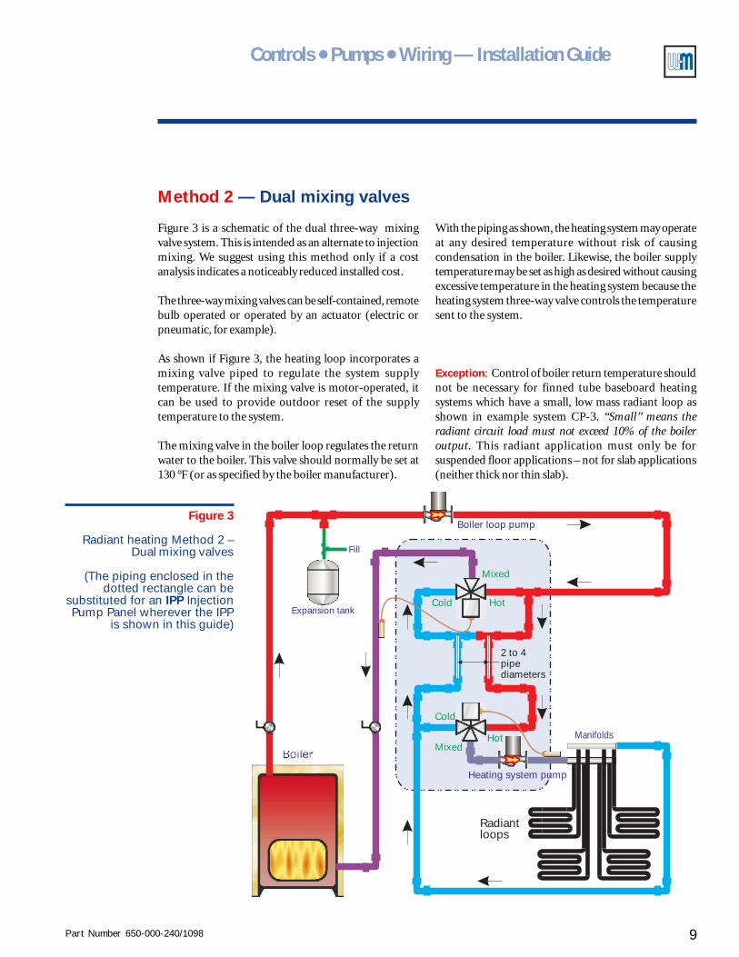
Method 2 — Dual mixing valves
Figure 3 is a schematic of the dual three-way mixingvalve system. This is intended as an alternate to injectionmixing. We suggest using this method only if a costanalysis indicates a noticeably reduced installed cost.
The three-way mixing valves can be self-contained, remotebulb operated or operated by an actuator (electric orpneumatic, for example).
As shown if Figure 3, the heating loop incorporates amixing valve piped to regulate the system supplytemperature. If the mixing valve is motor-operated, itcan be used to provide outdoor reset of the supplytemperature to the system.
The mixing valve in the boiler loop regulates the returnwater to the boiler. This valve should normally be set at130 °F (or as specified by the boiler manufacturer).
Figure 3
Radiant heating Method 2 –Dual mixing valves
(The piping enclosed in thedotted rectangle can be
substituted for an IPP InjectionPump Panel wherever the IPP
is shown in this guide)
Fill
Expansion tank
Boiler loop pump
Radiantloops
Manifolds
Heating system pump
Hot
Mixed
Mixed
Cold
Cold
2 to 4pipediameters
Hot
With the piping as shown, the heating system may operateat any desired temperature without risk of causingcondensation in the boiler. Likewise, the boiler supplytemperature may be set as high as desired without causingexcessive temperature in the heating system because theheating system three-way valve controls the temperaturesent to the system.
Exception: Control of boiler return temperature shouldnot be necessary for finned tube baseboard heatingsystems which have a small, low mass radiant loop asshown in example system CP-3. “Small” means theradiant circuit load must not exceed 10% of the boileroutput. This radiant application must only be forsuspended floor applications – not for slab applications(neither thick nor thin slab).
Part Number 650-000-240/109810
AlumiPAlumiPAlumiPAlumiPAlumiPeeeeexxxxx® ® ® ® ® Radiant TRadiant TRadiant TRadiant TRadiant Tubingubingubingubingubing
Why use primary/secondary piping?
III Primary/secondary piping
Traditional piping for residential hydronic heating uses series loop or two-pipe piping. Commercial
systems are usually two-pipe design. These piping designs lack the versatility and efficiency needed
for today's systems, particularly for radiant heating. Use primary/secondary piping for radiant
heating (and for any system using outdoor reset or energy management).
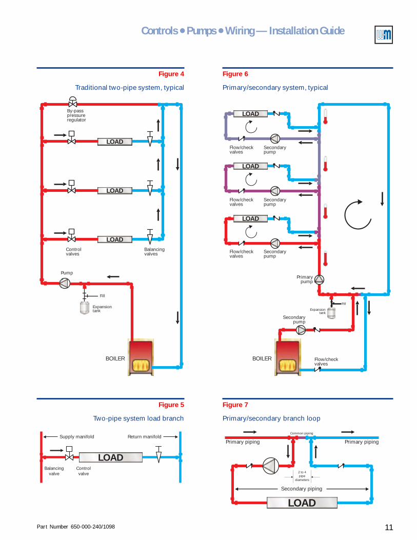
Look at Figures 4 through 7 for a comparison of a traditional two-pipe system to a primary/
secondary system.
Notice that the system pump must provide all the flow needed for every branch in a traditional
two-pipe system. But the flow in each secondary circuit (branch) of the primary/secondary
system is individually controlled by the loop components.
The need for a pump in every secondary circuit could be deemed a disadvantage. On the other
hand, the individual pumps provide primary/secondary systems with their versatility.
Disadvantages
Loop operations are
independent
Simple isolation for service
Piping and pump sizing
more efficient
No by-pass pressure regulator
Multiple boiler advantages
• The operation of pumps and control valves in a secondary circuit has no effect on pressure in
other secondary circuits of a primary/secondary system. There is no concern of over-pressuring
the control valve seats. In a traditional two-pipe system the pressure on control valves increases
as other loop valves close because the reduced flow causes the system pump to shift up on its
pump curve.
• Since closure of a secondary circuit has no impact on other secondary circuits, any circuit can
be isolated for service without impacting the rest of the system.
• Secondary circuit piping and components (pumps and valves) are sized only for the needs of
that circuit – not for the system as a whole.
• The flow and head loss through the primary pump never changes and the flow circuit is never
interrupted due to closure of control valves. On traditional two-pipe systems, the flow rate
changes constantly due to action of the control valves. And a by-pass pressure regulator is
needed to protect the pump from high head conditions (dead heading) as branch control
valves close.
• With multiple boilers on secondary loops, there is no flow through idle boilers. So stand-by
loss is virtually eliminated. Individual boilers can be isolated for service without affecting the
rest of the system.
Advantages This discussion emphasizes the advantages of primary/secondary piping in radiant heating systems.
You should see that the versatility of primary/secondary designs and the ability to more easily
control temperatures and flows in each loop make this approach essential.
Part Number 650-000-240/1098 11
Controls ● Pumps ● Wiring — Installation Guide
Fill
Secondarypump
Flow/checkvalves
Expansiontank
BOILER
Primarypump
LOAD
LOAD
LOAD
LOAD
Secondarypump
Secondarypump
Secondarypump
Flow/checkvalves
Flow/checkvalves
Flow/checkvalves
Fill
Expansiontank
Balancingvalves
Controlvalves
By-passpressureregulator
Pump
LOAD
LOAD
BOILER
Figure 7
Primary/secondary branch loop
Figure 6
Primary/secondary system, typical
Figure 5
Two-pipe system load branch
LOAD
2 to 4pipe
diameters
Primary piping
Secondary piping
Common piping
Primary pipingSupply manifold Return manifold
LOADBalancing
valveControlvalve
Figure 4
Traditional two-pipe system, typical
Part Number 650-000-240/109812
AlumiPAlumiPAlumiPAlumiPAlumiPeeeeexxxxx® ® ® ® ® Radiant TRadiant TRadiant TRadiant TRadiant Tubingubingubingubingubing
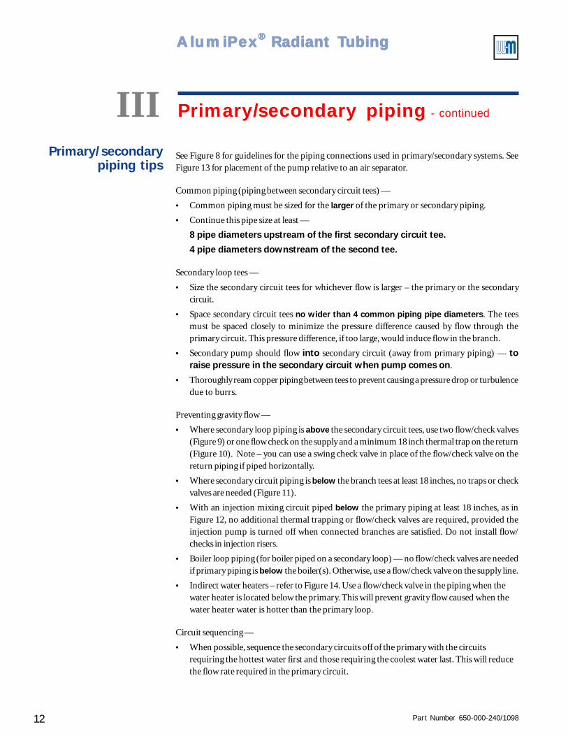
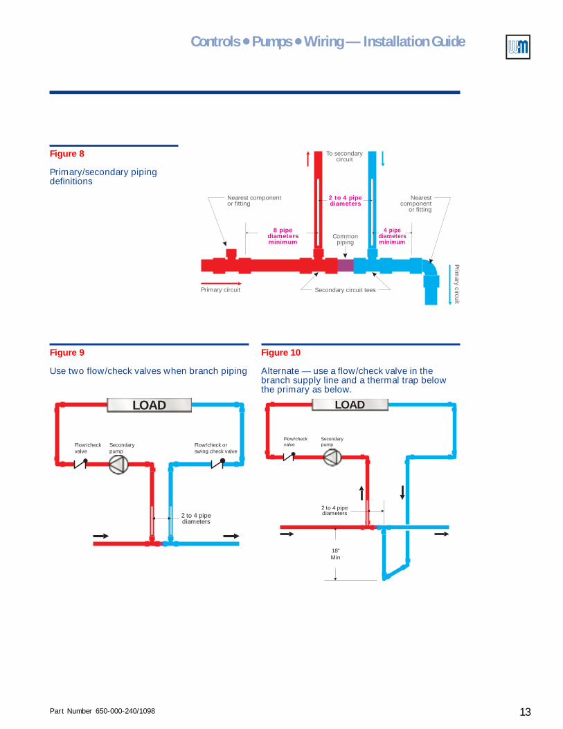
See Figure 8 for guidelines for the piping connections used in primary/secondary systems. SeeFigure 13 for placement of the pump relative to an air separator.
Common piping (piping between secondary circuit tees) —
• Common piping must be sized for the larger of the primary or secondary piping.
• Continue this pipe size at least —
8 pipe diameters upstream of the first secondary circuit tee.
4 pipe diameters downstream of the second tee.
Secondary loop tees —
• Size the secondary circuit tees for whichever flow is larger – the primary or the secondarycircuit.
• Space secondary circuit tees no wider than 4 common piping pipe diameters. The teesmust be spaced closely to minimize the pressure difference caused by flow through theprimary circuit. This pressure difference, if too large, would induce flow in the branch.
• Secondary pump should flow into secondary circuit (away from primary piping) — toraise pressure in the secondary circuit when pump comes on.
• Thoroughly ream copper piping between tees to prevent causing a pressure drop or turbulencedue to burrs.
Preventing gravity flow —
• Where secondary loop piping is above the secondary circuit tees, use two flow/check valves(Figure 9) or one flow check on the supply and a minimum 18 inch thermal trap on the return(Figure 10). Note – you can use a swing check valve in place of the flow/check valve on thereturn piping if piped horizontally.
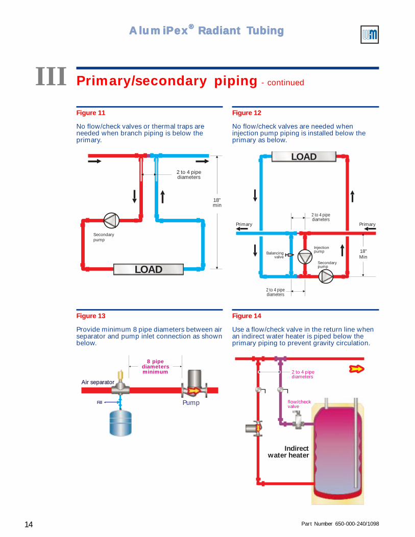
• Where secondary circuit piping is below the branch tees at least 18 inches, no traps or checkvalves are needed (Figure 11).
• With an injection mixing circuit piped below the primary piping at least 18 inches, as inFigure 12, no additional thermal trapping or flow/check valves are required, provided theinjection pump is turned off when connected branches are satisfied. Do not install flow/checks in injection risers.
• Boiler loop piping (for boiler piped on a secondary loop) — no flow/check valves are neededif primary piping is below the boiler(s). Otherwise, use a flow/check valve on the supply line.
• Indirect water heaters – refer to Figure 14. Use a flow/check valve in the piping when thewater heater is located below the primary. This will prevent gravity flow caused when thewater heater water is hotter than the primary loop.
Circuit sequencing —
• When possible, sequence the secondary circuits off of the primary with the circuitsrequiring the hottest water first and those requiring the coolest water last. This will reducethe flow rate required in the primary circuit.
Primary/secondarypiping tips
III Primary/secondary piping - continued
Part Number 650-000-240/1098 13
Controls ● Pumps ● Wiring — Installation Guide
Figure 9
Use two flow/check valves when branch piping
Figure 10
Alternate — use a flow/check valve in thebranch supply line and a thermal trap belowthe primary as below.
LOAD
Flow/check orswing check valve
2 to 4 pipediameters
Secondarypump
Flow/checkvalve
LOAD
18"Min
Secondarypump
Flow/checkvalve
2 to 4 pipediameters
4 pipediametersminimum
8 pipediametersminimum
Nearest componentor fitting
Nearestcomponent
or fitting
To secondarycircuit
Primary circuit
Commonpiping
Secondary circuit tees
Primary circuit
2 to 4 pipediameters
Figure 8
Primary/secondary pipingdefinitions
Part Number 650-000-240/109814
AlumiPAlumiPAlumiPAlumiPAlumiPeeeeexxxxx® ® ® ® ® Radiant TRadiant TRadiant TRadiant TRadiant Tubingubingubingubingubing
Figure 13
Provide minimum 8 pipe diameters between airseparator and pump inlet connection as shownbelow.
Fill Pump
8 pipediametersminimum
Air separator
Figure 14
Use a flow/check valve in the return line whenan indirect water heater is piped below theprimary piping to prevent gravity circulation.
Indirectwater heater
flow/checkvalve
2 to 4 pipediameters
Figure 12
No flow/check valves are needed wheninjection pump piping is installed below theprimary as below.
Figure 11
No flow/check valves or thermal traps areneeded when branch piping is below theprimary.
LOAD
Secondarypump
2 to 4 pipediameters
18”min
LOAD
18"Min
Secondarypump
InjectionpumpBalancing
valve
PrimaryPrimary
2 to 4 pipediameters
2 to 4 pipediameters
III Primary/secondary piping - continued
Part Number 650-000-240/1098 15
Controls ● Pumps ● Wiring — Installation Guide
IV Zoning radiant heating systems
A zone is defined as a heating circuit or group of heating circuits controlled by a commonthermostat (or other temperature sensing/regulating method). Radiant heat zoning is similar toother hydronic systems, but the versatility of radiant tubing applications introduces the need fordifferent supply temperatures to spaces – and different spaces may have very different needs.
When combining spaces for a zone, make sure they are similar with respect to —
❏❏❏❏❏ The type of radiant heat application in the space must be similar —• Slab on grade, thin slab, below floor, above floor, etc. — don’t mix system types on the
same zone.• Below floor applications usually require higher water temperature than other types.• The mass of a slab system responds differently from a low mass suspended floor system
(above floor or below floor tubing installation).
❏❏❏❏❏ Supply water temperatures required must be similar —• Select radiant circuits requiring similar water temperatures when combining in common
zones.• Availabe floor area will affect the supply temperature required. So floor area available in
spaces must be considered when combining on a zone.
❏❏❏❏❏ Internal and solar gain variations should be similar —• Kitchens, sun rooms and rooms with large window areas have different needs from
family rooms, bathrooms and bedrooms, for example.• Entry areas will have different responses because of the influx of cold air as doors are
opened.
❏❏❏❏❏ Finished flooring (tile, carpet, wood, etc.) should have similar R-values —• Carpet acts as an insulator, requiring higher water temperature to the tubing. Tile, on the
other hand, is a heat conductor and requires lower supply water temperature. Both havedifferent needs from wood or linoleum.
❏❏❏❏❏ Usage patterns should be similar —• Bedrooms should be zoned separately from high usage living areas, for example.
Combining spacesfor zoning
Using zone valvesand/or valve
actuators
Zone valves or valve actuators allow independent operation of zones. This provides a smarter,more adaptive system. Even the best designed radiant heating system may cause uncomfortablespace conditions if the space thermostat can't regulate the heat input to the space. With AlumiPexnickel-plated brass manifolds, optional valve actuators (2-wire or 4-wire) are available.
Use zone valves or valve actuators whenever possible, with the exception of some constantcirculation applications. Some zones of constant circulation systems should never have the flowstopped — for example, zones heating warehouse spaces adjacent to loading dock doors. (Keepthe water moving in these zones to reduce the potential for freeze-up should the heating source beoff while the loading doors are opened.)
When using constant circulation with zone valves or valve actuators, install a by-pass pressureregulator in the piping to provide a water path should all zones close for a time (see Figure 65).This will protect the circulator from cavitation caused by high head/low flow operation.
Use 4-wire valve actuators to allow the actuators to signal the heating system of the need for heat.For spaces with multiple tubing circuits, use one "master" 4-wire valve actuator on one of thecircuits, with 2-wire zone valve actuators on the remaining circuits (as shown in the examples atthe end of this Guide).
Try to combine small zones as “slave” zones to larger ones to prevent a small zone from being theonly heat zone during a call for heat to the boiler. (Using a buffer tank will also help to reducecycling of the boiler during light loads.)
Part Number 650-000-240/109816
AlumiPAlumiPAlumiPAlumiPAlumiPeeeeexxxxx® ® ® ® ® Radiant TRadiant TRadiant TRadiant TRadiant Tubingubingubingubingubing
When combining radiant circuits on manifolds, make sure the supply temperature requirementsof the connected circuits are similar (maximum 10 °F difference in design temperature). If circuitlengths vary by more than 10% from one another, provide means for flow balancing, preferablyAlumiPex® Manifolds with integral valves plus AlumiPex® Flow Indicators.
Suggestions for combining circuits at manifolds —
❏❏❏❏❏ Combined flow rate of all connected circuits on any manifold no greater than12 gpm.
❏❏❏❏❏ Maximum difference between design supply temperature in any two circuitsis 10 °F.
❏❏❏❏❏ Locate manifolds centrally to the heated spaces to reduce leader lengths.
❏❏❏❏❏ Limit leader length to approximately 50 feet, using multiple manifolds indifferent locations if necessary to accomplish this.
❏❏❏❏❏ Use a zone valve (or valve actuator) on each circuit to allow adaptive control.See Figures 16 and 17 for typical uses of zone valves and valve actuators.These diagrams also show the use of multiple manifolds – either where neededbecause of the zone size or because multiple temperatures (differing by morethan 10 °F) are required on the same or multiple zones.
❏❏❏❏❏ When using zone valves with constant circulation systems, install by-passpressure regulator between manifold supply and return to provide a flowpath for the circulator when all zone valves are closed.
Combining circuitson manifolds
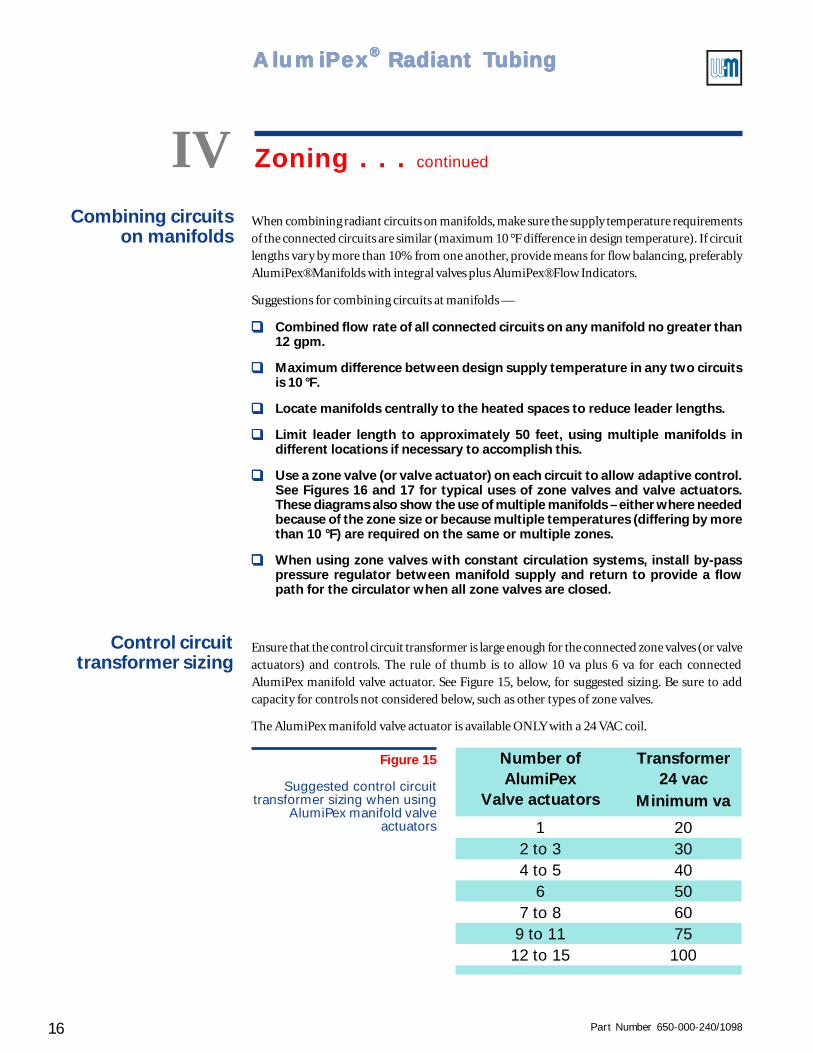
Ensure that the control circuit transformer is large enough for the connected zone valves (or valveactuators) and controls. The rule of thumb is to allow 10 va plus 6 va for each connectedAlumiPex manifold valve actuator. See Figure 15, below, for suggested sizing. Be sure to addcapacity for controls not considered below, such as other types of zone valves.
The AlumiPex manifold valve actuator is available ONLY with a 24 VAC coil.
Control circuittransformer sizing
Figure 15
Suggested control circuittransformer sizing when using
AlumiPex manifold valveactuators
Transformer24 vac
Minimum va
1 202 to 3 304 to 5 40
6 507 to 8 60
9 to 11 7512 to 15 100
Number ofAlumiPex
Valve actuators
IV Zoning . . . continued
Part Number 650-000-240/1098 17
Controls ● Pumps ● Wiring — Installation Guide
Figure 16
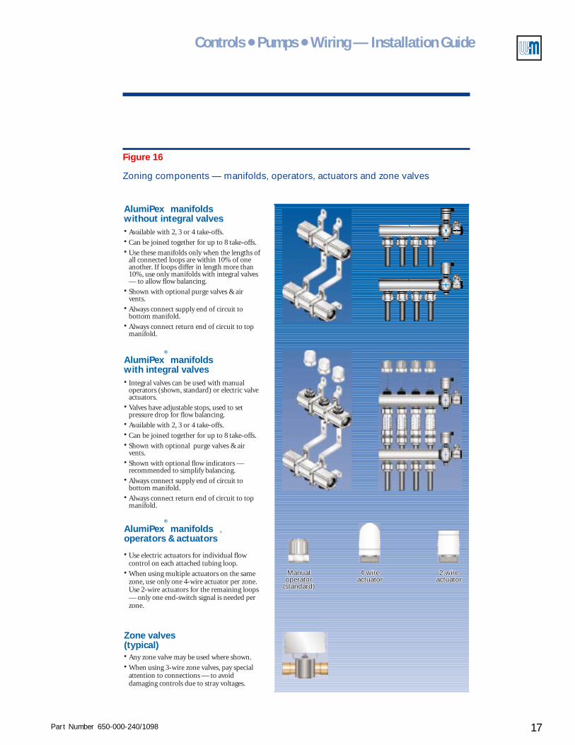
Zoning components — manifolds, operators, actuators and zone valves
•••
•
•
•
Available with 2, 3 or 4 take-offs.
Can be joined together for up to 8 take-offs.
Use these manifolds only when the lengths ofall connected loops are within 10% of oneanother. If loops differ in length more than10%, use only manifolds with integral valves— to allow flow balancing.
Shown with optional purge valves & airvents.
Always connect supply end of circuit tobottom manifold.
Always connect return end of circuit to topmanifold.
AlumiPex manifoldswithout integral valves
•
•
•••
•
•
Integral valves can be used with manualoperators (shown, standard) or electric valveactuators.
Valves have adjustable stops, used to setpressure drop for flow balancing.
Available with 2, 3 or 4 take-offs.
Can be joined together for up to 8 take-offs.
Shown with optional purge valves & airvents.
Shown with optional flow indicators —recommended to simplify balancing.
Always connect supply end of circuit tobottom manifold.
Always connect return end of circuit to topmanifold.
•
AlumiPex®
manifoldswith integral valves
2-wireactuator2-wire
actuator4-wire
actuator4-wire
actuatorManualoperator
(standard)
Manualoperator
(standard)
•
•
Use electric actuators for individual flowcontrol on each attached tubing loop.
When using multiple actuators on the samezone, use only one 4-wire actuator per zone.Use 2-wire actuators for the remaining loops— only one end-switch signal is needed perzone.
AlumiPex®
manifoldsoperators & actuators
••
Any zone valve may be used where shown.
When using 3-wire zone valves, pay specialattention to connections — to avoiddamaging controls due to stray voltages.
Zone valves(typical)
,
Part Number 650-000-240/109818
AlumiPAlumiPAlumiPAlumiPAlumiPeeeeexxxxx® ® ® ® ® Radiant TRadiant TRadiant TRadiant TRadiant Tubingubingubingubingubing
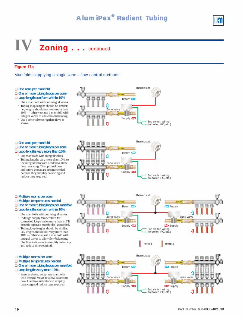
Figure 17a
Manifolds supplying a single zone – flow control methods
End switch wiring(to boiler, IPC, etc.)
Thermostat
End switch wiring(to boiler, IPC, etc.)
Thermostat
End switch wiring(to boiler, IPC, etc.)
Thermostat
Return
Supply
Zone valve
Return
Zone valve
Supply
Return
Return
Zone valve
Zone valve
Supply
Supply
End switch wiring(to boiler, IPC, etc.)
Thermostat
Return Return
Supply Supply
Zone valve Zone valve
••
•
Use a manifold without integral valves.Tubing loop lengths should be similar;i.e., lengths should not vary more than10% — otherwise, use a manifold withintegral valves to allow flow balancing.Use a zone valve to regulate flow, asshown.
❏
❏
❏
One zone per manifoldOne or more tubing loops per zoneLoop lengths uniform within 10%
••
Use manifolds with integral valves.Tubing lengths vary more than 10%, sothe integral valves are needed to allowflow balancing. The optional flowindicators shown are recommendedbecause they simplify balancing andreduce time required.
❏
❏
❏
One zone per manifoldOne or more tubing loops per zoneLoop lengths vary more than 10%
••
•
Use manifolds without integral valves.If design supply temperature forconnected loops varies more than ± 5°F,provide separate manifold(s) as needed.
Use flow indicators to simplify balancingand reduce time required.
• Tubing loop lengths should be similar;i.e., lengths should not vary more than10% — otherwise, use a manifold withintegral valves to allow flow balancing.
❏
❏
❏
❏
Multiple rooms per zoneMultiple temperatures neededOne or more tubing loops per manifoldLoop lengths uniform within 10%
• Same as above, except use manifoldswith integral valves to allow balancingflow. Use flow indicators to simplifybalancing and reduce time required.
❏
❏
❏
❏
Multiple rooms per zoneMultiple temperatures neededOne or more tubing loops per manifoldLoop lengths vary more 10%
Temp 2Temp 1
IV Zoning . . . continued
Part Number 650-000-240/1098 19
Controls ● Pumps ● Wiring — Installation Guide
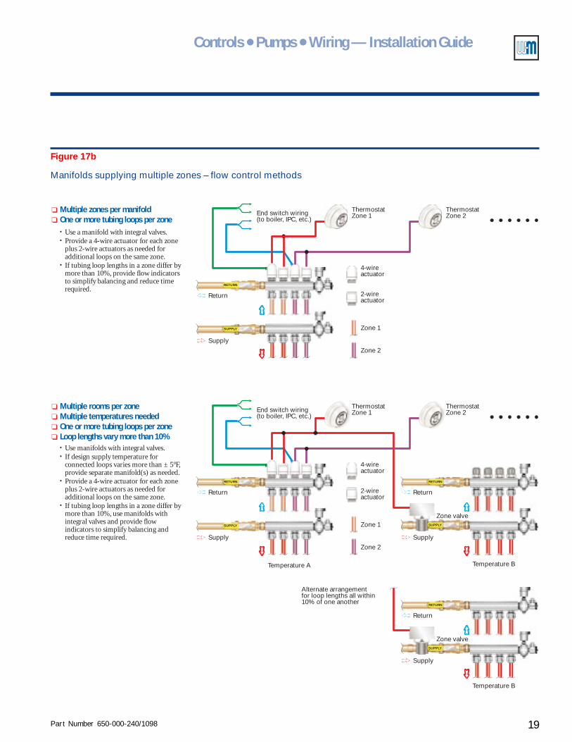
Figure 17b
Manifolds supplying multiple zones – flow control methods
End switch wiring(to boiler, IPC, etc.)
ThermostatZone 1
Zone 1
Zone 2
ThermostatZone 2
Return
Supply
SUPPLY
Zone valve
End switch wiring(to boiler, IPC, etc.)
ThermostatZone 1
Zone 1
Zone 2
Temperature A Temperature B
Temperature B
ThermostatZone 2
Return Return
Supply Supply
SUPPLY
RETURNRETURN
4-wireactuator
2-wireactuator
SUPPLY
RETURN
4-wireactuator
2-wireactuator
SUPPLY
Zone valve
Return
Supply
RETURN
Alternate arrangementfor loop lengths all within10% of one another
••
•
Use a manifold with integral valves.Provide a 4-wire actuator for each zoneplus 2-wire actuators as needed foradditional loops on the same zone.If tubing loop lengths in a zone differ bymore than 10%, provide flow indicatorsto simplify balancing and reduce timerequired.
❏
❏
Multiple zones per manifoldOne or more tubing loops per zone
••
•
•
Use manifolds with integral valves.If design supply temperature forconnected loops varies more than ± 5°F,provide separate manifold(s) as needed.Provide a 4-wire actuator for each zoneplus 2-wire actuators as needed foradditional loops on the same zone.If tubing loop lengths in a zone differ bymore than 10%, use manifolds withintegral valves and provide flowindicators to simplify balancing andreduce time required.
❏
❏
❏
❏
Multiple rooms per zoneMultiple temperatures neededOne or more tubing loops per zoneLoop lengths vary more than 10%
Part Number 650-000-240/109820
AlumiPAlumiPAlumiPAlumiPAlumiPeeeeexxxxx® ® ® ® ® Radiant TRadiant TRadiant TRadiant TRadiant Tubingubingubingubingubing
Supply
wat
er t
emper
ature
Outdoor temperature
R=1.5(1.5 to 1 Ratio)
R=1(1 to 1 Ratio)
R=0.67(1 to 1.5 Ratio)
70 -1070
100
130
160
190
103050
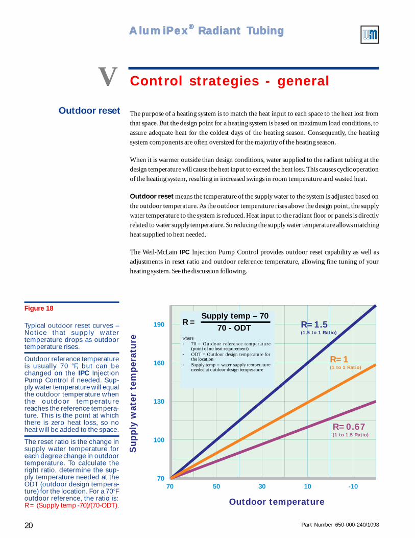
V Control strategies - general
The purpose of a heating system is to match the heat input to each space to the heat lost from
that space. But the design point for a heating system is based on maximum load conditions, to
assure adequate heat for the coldest days of the heating season. Consequently, the heating
system components are often oversized for the majority of the heating season.
When it is warmer outside than design conditions, water supplied to the radiant tubing at the
design temperature will cause the heat input to exceed the heat loss. This causes cyclic operation
of the heating system, resulting in increased swings in room temperature and wasted heat.
Outdoor reset means the temperature of the supply water to the system is adjusted based on
the outdoor temperature. As the outdoor temperature rises above the design point, the supply
water temperature to the system is reduced. Heat input to the radiant floor or panels is directly
related to water supply temperature. So reducing the supply water temperature allows matching
heat supplied to heat needed.
The Weil-McLain IPC Injection Pump Control provides outdoor reset capability as well as
adjustments in reset ratio and outdoor reference temperature, allowing fine tuning of your
heating system. See the discussion following.
Outdoor reset
Figure 18
Typical outdoor reset curves –Notice that supply watertemperature drops as outdoortemperature rises.
Outdoor reference temperatureis usually 70 °F, but can bechanged on the IPC InjectionPump Control if needed. Sup-ply water temperature will equalthe outdoor temperature whenthe outdoor temperaturereaches the reference tempera-ture. This is the point at whichthere is zero heat loss, so noheat will be added to the space.
The reset ratio is the change insupply water temperature foreach degree change in outdoortemperature. To calculate theright ratio, determine the sup-ply temperature needed at theODT (outdoor design tempera-ture) for the location. For a 70°Foutdoor reference, the ratio is:R = (Supply temp -70)/(70-ODT).
R =Supply temp – 70
70 - ODTwhere• 70 = Outdoor reference temperature
(point of no heat requirement)• ODT = Outdoor design temperature for
the location• Supply temp = water supply temperature
needed at outdoor design temperature
Part Number 650-000-240/1098 21
Controls ● Pumps ● Wiring — Installation Guide
Advantages of outdoor reset• Fewer cycles of the heating components (boiler, zone controls and pumps).
• Smaller changes in room temperature.
• Floors will feel more comfortable because floor temperature variations will be smaller.
• Reduced thermal stressing of wood flooring over heated slabs. Wood is less prone to cuppingor cracking when undergoing gradual temperature changes.
• Reduced expansion noise in distribution piping.
• Reduced heat loss from distribution piping because of lower supply temperature.
• From 10% to 15% reduction in fuel usage due to reduced cycling and lower distributiontemperature.
• Can also be used effectively with baseboard and panel radiation.
Advantages of fixed temperature control• Faster warm-up from cold start conditions in mild weather.
• Faster reaction to sudden influx of cold air into the space.
• Fewer control adjustments required.
• Can be done with relatively low cost three-way or two-way temperature regulating valves(provided the boiler return piping protects the boiler from condensation and thermal shock).
In general, the best performance for the radiant system will come from using outdoor reset with
zone valves on each zone. With the outdoor reset control correctly adjusted, and flow rates and
supply temperatures for each zone set properly, it will probably not be necessary to set the
circulator for constant operation because the matching of heat input to heat loss will keep the
circulator on most of the time anyway.
Summary
Constant circulation Constant operation of the distribution circulator throughout the system reduces temperature
swings in the floor and the heated space. Consider using constant circulation for wood floor
applications because it will reduce thermal stressing of wood flooring.
Use constant circulation on zones supplying heat to warehouse areas adjacent to load dock
doors. With constant circulation in the tubing, the possibility of freeze-up is reduced, even for
times when the door is open and the boiler is off. This is because the circulating water can take
stored heat from other floor areas to replace the high heat loss near the door.
A note on application of constant circulation —
Since zone valves are generally not used on constant circulation systems, all zones must have
similar requirements; i.e., if some zones have significant solar gain, these zones may be overheated
in a constant circulation system. If you plan to use constant circulation on such systems, provide
zone valves to segment the system and a by-pass pressure regulator to protect the pump from
running with no flow should all zone valves close at the same time.
Part Number 650-000-240/109822
AlumiPAlumiPAlumiPAlumiPAlumiPeeeeexxxxx® ® ® ® ® Radiant TRadiant TRadiant TRadiant TRadiant Tubingubingubingubingubing
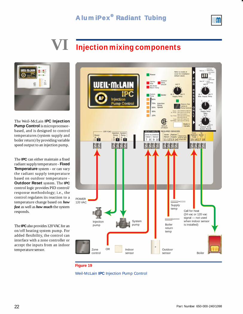
Figure 19
Weil-McLain IPC Injection Pump Control
The Weil-McLain IPC InjectionPump Control is microprocessor-based, and is designed to controltemperatures (system supply andboiler return) by providing variablespeed output to an injection pump.
The IPC can either maintain a fixedradiant supply temperature - FixedTemperature system - or can varythe radiant supply temperaturebased on outdoor temperature -Outdoor Reset system. The IPCcontrol logic provides PID control/response methodology; i.e., thecontrol regulates its reaction to atemperature change based on howfast as well as how much the systemresponds.
The IPC also provides 120 VAC for anon/off heating system pump. Foradded flexibility, the control caninterface with a zone controller oraccept the inputs from an indoortemperature sensor.
LR 58223NRTL/C
OutdoorTempShutoff
Press to TestLamps &Pump Controls
Refer to inside ofcover for installationdefault values
BoilerSupply Temp. Max. Supply Temp.
Supply TempRatio
Outdoor TempSystem Shutoff
185 °F 185 °F
100 °F
85 °F 85 °F
40 °F
0.2 3.6
3
21
140 °F 140 °F
70 °F
InjectionPumpSpeed
10
30
90
70
50
SystemPump
Min BoilerReturn Temp
Call ForHeat
%
%
%
%
%
Power
REQUIRED SENSORSRESET INPUTS
Zone orIndoor
InjectionPumpN L
SystemPumpN L
PowerN L
120 V (ac)
BoilerReturn
FromRadiantT-stat
ToBoiler
T-T
Made inCanada
RadiantSupply
OutdoorSensor Signal wiring
must be ratedat least 300V
Power: 120 V 50/60 Hz 1500 VA120 V (ac) 2.4 A 1/5 hp.
120 V (ac) 5 A 1/6 hp.
120 V (ac) 10 A 1/3 hp.
24 to 120 V (ac) 2 VA
fuse T2.5 A 250 V
pilot duty 240 VA
Inj. Pump:
Sys. Pump
T-stat:BLR Relay:
®
3 7 11 151 8 12 162 5 9 13 176 10 14 184
FOR
RESET
ONLY
1 2 3
Reset Off
Reset On
On/OffSystem Pump
IndoorSensor Input
Zone ControlInput
ContinuousSystem Pump
Injectionpump
Systempump
ORZonecontrol
Indoorsensor
Outdoorsensor
Call for heat(24 vac or 120 vacsignal — not usedwhen indoor sensoris installed)
Supplytemp
Boilerreturntemp
Boiler
POWER120 VAC
VI Injection mixing components
Part Number 650-000-240/1098 23
Controls ● Pumps ● Wiring — Installation Guide
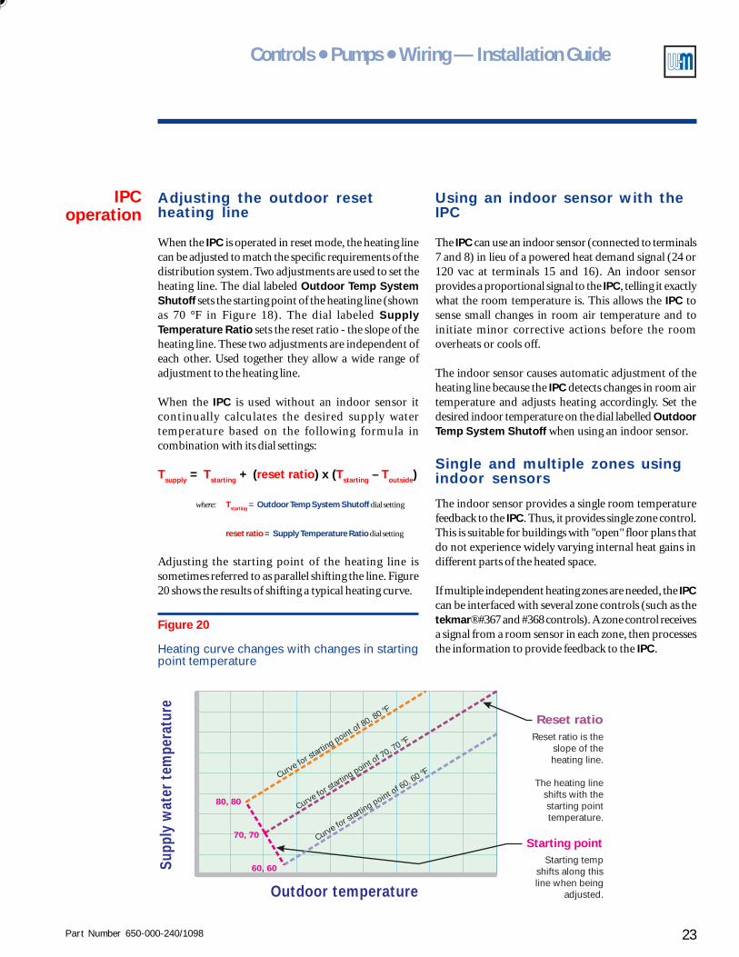
Adjusting the outdoor resetheating line
When the IPC is operated in reset mode, the heating linecan be adjusted to match the specific requirements of thedistribution system. Two adjustments are used to set theheating line. The dial labeled Outdoor Temp SystemShutoff sets the starting point of the heating line (shownas 70 °F in Figure 18). The dial labeled SupplyTemperature Ratio sets the reset ratio - the slope of theheating line. These two adjustments are independent ofeach other. Used together they allow a wide range ofadjustment to the heating line.
When the IPC is used without an indoor sensor itcontinually calculates the desired supply watertemperature based on the following formula incombination with its dial settings:
Tsupply = Tstarting + (reset ratio) x (Tstarting – Toutside)
where: Tstarting = Outdoor Temp System Shutoff dial setting
reset ratio = Supply Temperature Ratio dial setting
Adjusting the starting point of the heating line issometimes referred to as parallel shifting the line. Figure20 shows the results of shifting a typical heating curve.
IPCoperation
Supp
ly w
ater
tem
pera
ture
Outdoor temperature
70, 70
60, 60
80, 80
Reset ratioReset ratio is the
slope of theheating line.
The heating lineshifts with thestarting pointtemperature.
Starting pointStarting temp
shifts along thisline when being
adjusted.
Curve for st
arting point o
f 80, 80 °F
Curve for st
arting point o
f 70, 70 °F
Curve for st
arting point o
f 60, 60 °F
Figure 20
Heating curve changes with changes in startingpoint temperature
Using an indoor sensor with theIPC
The IPC can use an indoor sensor (connected to terminals7 and 8) in lieu of a powered heat demand signal (24 or120 vac at terminals 15 and 16). An indoor sensorprovides a proportional signal to the IPC, telling it exactlywhat the room temperature is. This allows the IPC tosense small changes in room air temperature and toinitiate minor corrective actions before the roomoverheats or cools off.
The indoor sensor causes automatic adjustment of theheating line because the IPC detects changes in room airtemperature and adjusts heating accordingly. Set thedesired indoor temperature on the dial labelled OutdoorTemp System Shutoff when using an indoor sensor.
Single and multiple zones usingindoor sensors
The indoor sensor provides a single room temperaturefeedback to the IPC. Thus, it provides single zone control.This is suitable for buildings with "open" floor plans thatdo not experience widely varying internal heat gains indifferent parts of the heated space.
If multiple independent heating zones are needed, the IPCcan be interfaced with several zone controls (such as thetekmar® #367 and #368 controls). A zone control receivesa signal from a room sensor in each zone, then processesthe information to provide feedback to the IPC.
Part Number 650-000-240/109824
AlumiPAlumiPAlumiPAlumiPAlumiPeeeeexxxxx® ® ® ® ® Radiant TRadiant TRadiant TRadiant TRadiant Tubingubingubingubingubing
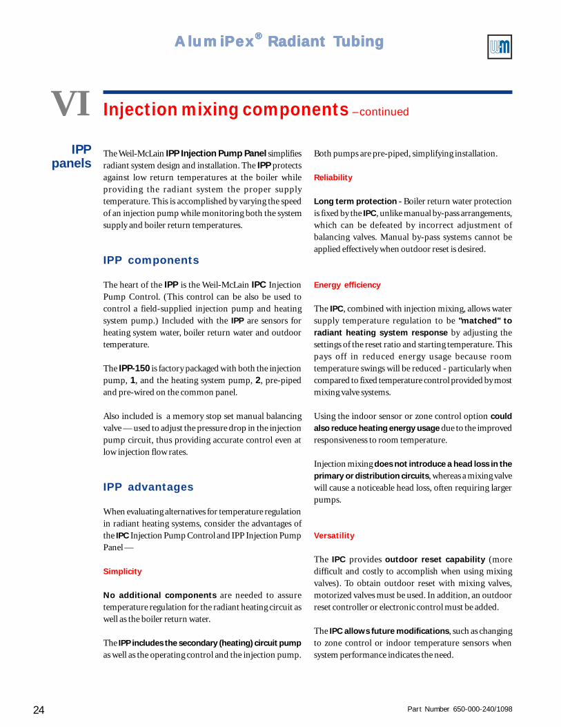
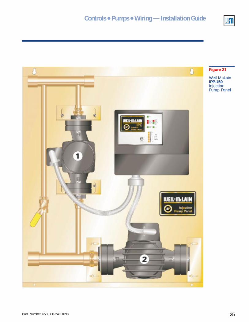
The Weil-McLain IPP Injection Pump Panel simplifiesradiant system design and installation. The IPP protectsagainst low return temperatures at the boiler whileproviding the radiant system the proper supplytemperature. This is accomplished by varying the speedof an injection pump while monitoring both the systemsupply and boiler return temperatures.
IPP components
The heart of the IPP is the Weil-McLain IPC InjectionPump Control. (This control can be also be used tocontrol a field-supplied injection pump and heatingsystem pump.) Included with the IPP are sensors forheating system water, boiler return water and outdoortemperature.
The IPP-150 is factory packaged with both the injectionpump, 1, and the heating system pump, 2, pre-pipedand pre-wired on the common panel.
Also included is a memory stop set manual balancingvalve — used to adjust the pressure drop in the injectionpump circuit, thus providing accurate control even atlow injection flow rates.
IPP advantages
When evaluating alternatives for temperature regulationin radiant heating systems, consider the advantages ofthe IPC Injection Pump Control and IPP Injection PumpPanel —
Simplicity
No additional components are needed to assuretemperature regulation for the radiant heating circuit aswell as the boiler return water.
The IPP includes the secondary (heating) circuit pumpas well as the operating control and the injection pump.
VI Injection mixing components – continued
IPPpanels
Both pumps are pre-piped, simplifying installation.
Reliability
Long term protection - Boiler return water protectionis fixed by the IPC, unlike manual by-pass arrangements,which can be defeated by incorrect adjustment ofbalancing valves. Manual by-pass systems cannot beapplied effectively when outdoor reset is desired.
Energy efficiency
The IPC, combined with injection mixing, allows watersupply temperature regulation to be "matched" toradiant heating system response by adjusting thesettings of the reset ratio and starting temperature. Thispays off in reduced energy usage because roomtemperature swings will be reduced - particularly whencompared to fixed temperature control provided by mostmixing valve systems.
Using the indoor sensor or zone control option couldalso reduce heating energy usage due to the improvedresponsiveness to room temperature.
Injection mixing does not introduce a head loss in theprimary or distribution circuits, whereas a mixing valvewill cause a noticeable head loss, often requiring largerpumps.
Versatility
The IPC provides outdoor reset capability (moredifficult and costly to accomplish when using mixingvalves). To obtain outdoor reset with mixing valves,motorized valves must be used. In addition, an outdoorreset controller or electronic control must be added.
The IPC allows future modifications, such as changingto zone control or indoor temperature sensors whensystem performance indicates the need.
Part Number 650-000-240/1098 25
Controls ● Pumps ● Wiring — Installation Guide
Figure 21
Weil-McLainIPP-150InjectionPump Panel
Part Number 650-000-240/109826
AlumiPAlumiPAlumiPAlumiPAlumiPeeeeexxxxx® ® ® ® ® Radiant TRadiant TRadiant TRadiant TRadiant Tubingubingubingubingubing
VII Determining flow rates
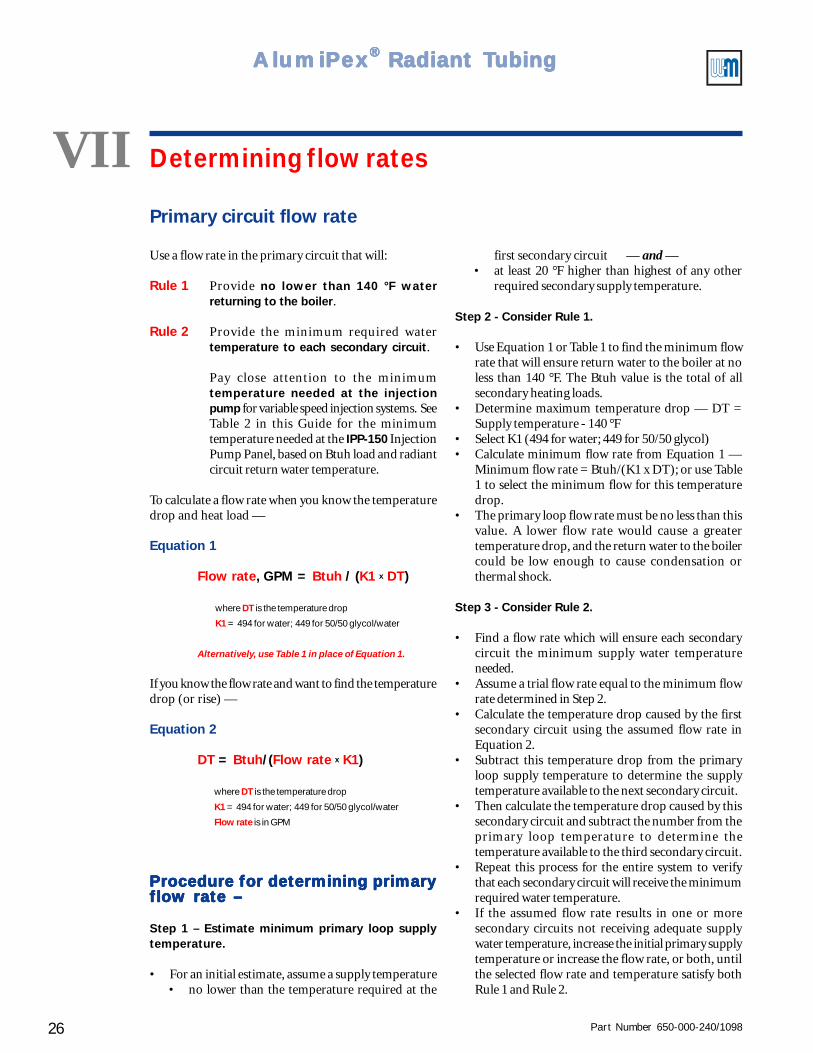
Use a flow rate in the primary circuit that will:
Rule 1 Provide no lower than 140 °F waterreturning to the boiler.
Rule 2 Provide the minimum required watertemperature to each secondary circuit.
Pay close attention to the minimumtemperature needed at the injectionpump for variable speed injection systems. SeeTable 2 in this Guide for the minimumtemperature needed at the IPP-150 InjectionPump Panel, based on Btuh load and radiantcircuit return water temperature.
To calculate a flow rate when you know the temperaturedrop and heat load —
Equation 1
Flow rate, GPM = Btuh / (K1 x DT)
where DT is the temperature drop
K1 = 494 for water; 449 for 50/50 glycol/water
Alternatively, use Table 1 in place of Equation 1.
If you know the flow rate and want to find the temperaturedrop (or rise) —
Equation 2
DT = Btuh/(Flow rate x K1)
where DT is the temperature drop
K1 = 494 for water; 449 for 50/50 glycol/water
Flow rate is in GPM
Procedure for determining primaryProcedure for determining primaryProcedure for determining primaryProcedure for determining primaryProcedure for determining primaryflow rate –flow rate –flow rate –flow rate –flow rate –
Step 1 – Estimate minimum primary loop supplytemperature.
• For an initial estimate, assume a supply temperature• no lower than the temperature required at the
Primary circuit flow rate
first secondary circuit — and —• at least 20 °F higher than highest of any other
required secondary supply temperature.
Step 2 - Consider Rule 1.
• Use Equation 1 or Table 1 to find the minimum flowrate that will ensure return water to the boiler at noless than 140 °F. The Btuh value is the total of allsecondary heating loads.
• Determine maximum temperature drop — DT =Supply temperature - 140 °F
• Select K1 (494 for water; 449 for 50/50 glycol)• Calculate minimum flow rate from Equation 1 —
Minimum flow rate = Btuh/(K1 x DT); or use Table1 to select the minimum flow for this temperaturedrop.
• The primary loop flow rate must be no less than thisvalue. A lower flow rate would cause a greatertemperature drop, and the return water to the boilercould be low enough to cause condensation orthermal shock.
Step 3 - Consider Rule 2.
• Find a flow rate which will ensure each secondarycircuit the minimum supply water temperatureneeded.
• Assume a trial flow rate equal to the minimum flowrate determined in Step 2.
• Calculate the temperature drop caused by the firstsecondary circuit using the assumed flow rate inEquation 2.
• Subtract this temperature drop from the primaryloop supply temperature to determine the supplytemperature available to the next secondary circuit.
• Then calculate the temperature drop caused by thissecondary circuit and subtract the number from theprimary loop temperature to determine thetemperature available to the third secondary circuit.
• Repeat this process for the entire system to verifythat each secondary circuit will receive the minimumrequired water temperature.
• If the assumed flow rate results in one or moresecondary circuits not receiving adequate supplywater temperature, increase the initial primary supplytemperature or increase the flow rate, or both, untilthe selected flow rate and temperature satisfy bothRule 1 and Rule 2.
Part Number 650-000-240/1098 27
Controls ● Pumps ● Wiring — Installation Guide
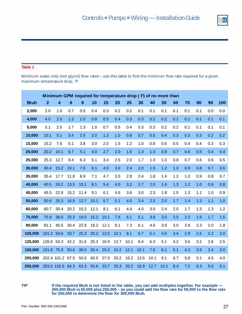
Table 1
Minimum water only (not glycol) flow rates – use this table to find the minimum flow rate required for a givenmaximum temperature drop, °F
TIP If the required Btuh is not listed in the table, you can add multiples together. For example —300,000 Btuh is 50,000 plus 250,000 – so you could add the flow rate for 50,000 to the flow ratefor 250,000 to determine the flow for 300,000 Btuh.
Btuh 2 4 6 8 10 15 20 25 30 40 50 60 70 80 90 100
2,000 2.0 1.0 0.7 0.5 0.4 0.3 0.2 0.2 0.1 0.1 0.1 0.1 0.1 0.1 0.0 0.0
4,000 4.0 2.0 1.3 1.0 0.8 0.5 0.4 0.3 0.3 0.2 0.2 0.1 0.1 0.1 0.1 0.1
5,000 5.1 2.5 1.7 1.3 1.0 0.7 0.5 0.4 0.3 0.3 0.2 0.2 0.1 0.1 0.1 0.1
10,000 10.1 5.1 3.4 2.5 2.0 1.3 1.0 0.8 0.7 0.5 0.4 0.3 0.3 0.3 0.2 0.2
15,000 15.2 7.6 5.1 3.8 3.0 2.0 1.5 1.2 1.0 0.8 0.6 0.5 0.4 0.4 0.3 0.3
20,000 20.2 10.1 6.7 5.1 4.0 2.7 2.0 1.6 1.3 1.0 0.8 0.7 0.6 0.5 0.4 0.4
25,000 25.3 12.7 8.4 6.3 5.1 3.4 2.5 2.0 1.7 1.3 1.0 0.8 0.7 0.6 0.6 0.5
30,000 30.4 15.2 10.1 7.6 6.1 4.0 3.0 2.4 2.0 1.5 1.2 1.0 0.9 0.8 0.7 0.6
35,000 35.4 17.7 11.8 8.9 7.1 4.7 3.5 2.8 2.4 1.8 1.4 1.2 1.0 0.9 0.8 0.7
40,000 40.5 20.2 13.5 10.1 8.1 5.4 4.0 3.2 2.7 2.0 1.6 1.3 1.2 1.0 0.9 0.8
45,000 45.5 22.8 15.2 11.4 9.1 6.1 4.6 3.6 3.0 2.3 1.8 1.5 1.3 1.1 1.0 0.9
50,000 50.6 25.3 16.9 12.7 10.1 6.7 5.1 4.0 3.4 2.5 2.0 1.7 1.4 1.3 1.1 1.0
60,000 60.7 30.4 20.2 15.2 12.1 8.1 6.1 4.9 4.0 3.0 2.4 2.0 1.7 1.5 1.3 1.2
75,000 75.9 38.0 25.3 19.0 15.2 10.1 7.6 6.1 5.1 3.8 3.0 2.5 2.2 1.9 1.7 1.5
90,000 91.1 45.5 30.4 22.8 18.2 12.1 9.1 7.3 6.1 4.6 3.6 3.0 2.6 2.3 2.0 1.8
100,000 101.2 50.6 33.7 25.3 20.2 13.5 10.1 8.1 6.7 5.1 4.0 3.4 2.9 2.5 2.2 2.0
125,000 126.5 63.3 42.2 31.6 25.3 16.9 12.7 10.1 8.4 6.3 5.1 4.2 3.6 3.2 2.8 2.5
150,000 151.8 75.9 50.6 38.0 30.4 20.2 15.2 12.1 10.1 7.6 6.1 5.1 4.3 3.8 3.4 3.0
200,000 202.4 101.2 67.5 50.6 40.5 27.0 20.2 16.2 13.5 10.1 8.1 6.7 5.8 5.1 4.5 4.0
250,000 253.0 126.5 84.3 63.3 50.6 33.7 25.3 20.2 16.9 12.7 10.1 8.4 7.2 6.3 5.6 5.1
Minimum GPM required for temperature drop ( F) of no more than
Part Number 650-000-240/109828
AlumiPAlumiPAlumiPAlumiPAlumiPeeeeexxxxx® ® ® ® ® Radiant TRadiant TRadiant TRadiant TRadiant Tubingubingubingubingubing
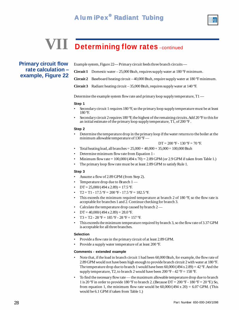
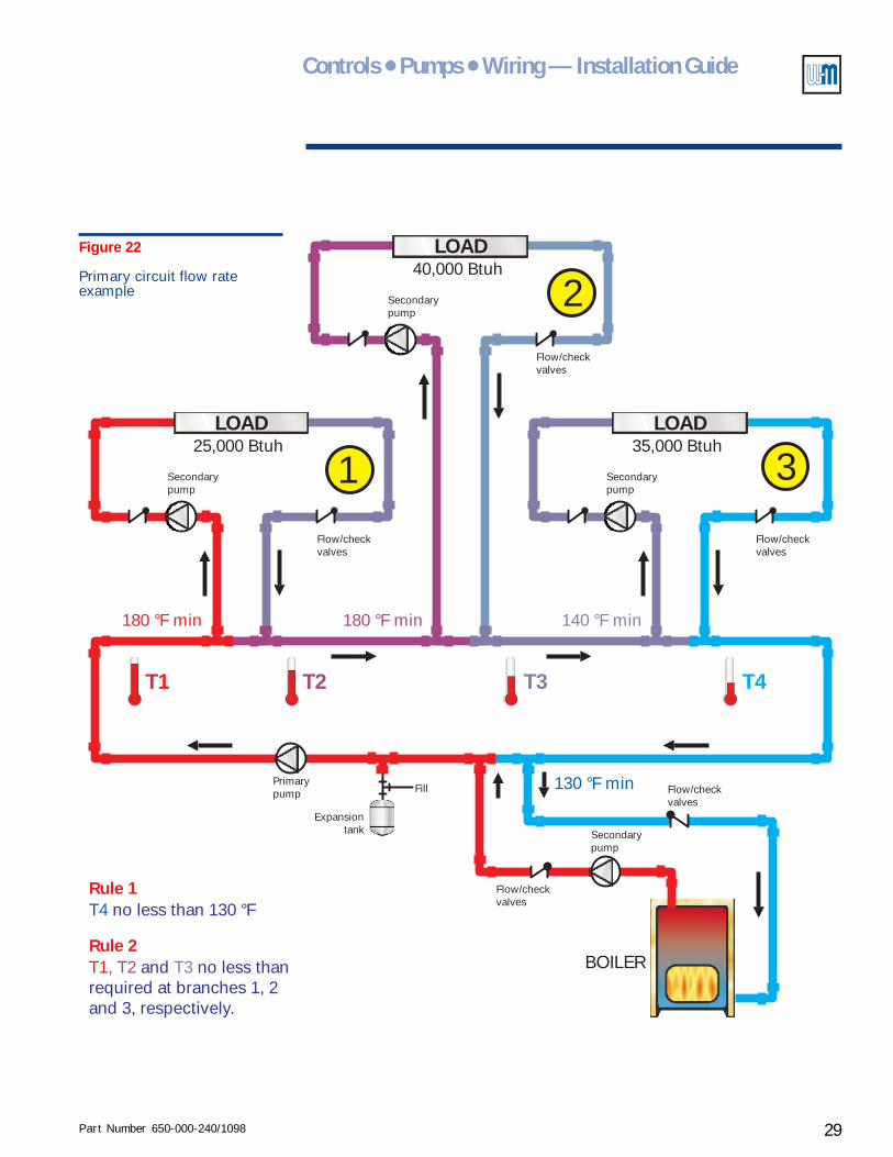
Example system, Figure 22— Primary circuit feeds three branch circuits —
Circuit 1 Domestic water – 25,000 Btuh, requires supply water at 180 °F minimum.
Circuit 2 Baseboard heating circuit – 40,000 Btuh, require supply water at 180 °F minimum.
Circuit 3 Radiant heating circuit – 35,000 Btuh, requires supply water at 140 °F.
Determine the example system flow rate and primary loop supply temperature, T1 —
Step 1• Secondary circuit 1 requires 180 °F, so the primary loop supply temperature must be at least
180 °F.• Secondary circuit 2 requires 180 °F, the highest of the remaining circuits. Add 20 °F to this for
an initial estimate of the primary loop supply temperature, T1, of 200 °F .
Step 2• Determine the temperature drop in the primary loop if the water returns to the boiler at the
minimum allowable temperature of 130 °F —
DT = 200 °F - 130 °F = 70 °F.
• Total heating load, all branches = 25,000 + 40,000 + 35,000 = 100,000 Btuh
• Determine minimum flow rate from Equation 1 -
• Minimum flow rate = 100,000/(494 x 70) = 2.89 GPM (or 2.9 GPM if taken from Table 1.)
• The primary loop flow rate must be at least 2.89 GPM to satisfy Rule 1.
Step 3• Assume a flow of 2.89 GPM (from Step 2).
• Temperature drop due to Branch 1 —
• DT = 25,000/(494 x 2.89) = 17.5 °F.
• T2 = T1 - 17.5 °F = 200 °F - 17.5 °F = 182.5 °F.
• This exceeds the minimum required temperature at branch 2 of 180 °F, so the flow rate isacceptable for branches 1 and 2. Continue checking for branch 3.
• Calculate the temperature drop caused by branch 2 —
• DT = 40,000/(494 x 2.89) = 28.0 °F.
• T3 = T2 - 28 °F = 185 °F - 28 °F = 157 °F.
• This exceeds the minimum temperature required by branch 3, so the flow rate of 3.37 GPMis acceptable for all three branches.
Selection• Provide a flow rate in the primary circuit of at least 2.89 GPM.• Provide a supply water temperature of at least 200 °F.
Comments - extended example
• Note that, if the load in branch circuit 1 had been 60,000 Btuh, for example, the flow rate of2.89 GPM would not have been high enough to provide branch circuit 2 with water at 180 °F.The temperature drop due to branch 1 would have been 60,000/(494 x 2.89) = 42 °F. And thesupply temperature, T2, to branch 2 would have been 200 °F - 42 °F = 158 °F.
• To find the necessary flow rate — the maximum allowable temperature drop due to branch1 is 20 °F in order to provide 180 °F to branch 2. (Because DT = 200 °F - 180 °F = 20 °F.) So,from equation 1, the minimum flow rate would be 60,000/(494 x 20) = 6.07 GPM. (Thiswould be 6.1 GPM if taken from Table 1.)
VII Determining flow rates - continued
Primary circuit flowrate calculation –
example, Figure 22
Part Number 650-000-240/1098 29
Controls ● Pumps ● Wiring — Installation Guide
Secondarypump
Flow/checkvalves
Flow/checkvalves
Fill
Expansiontank
BOILER
Primarypump
T1 T4T2 T3
Rule 1T4 no less than 130 °F
Rule 2T1, T2 and no less thanrequired at branches 1, 2and 3, respectively.
T3
180 °F min180 °F min 140 °F min
130 °F min
LOAD LOAD
Secondarypump
Secondarypump
125,000 Btuh 35,000 Btuh
Flow/checkvalves
Flow/checkvalves
LOAD
240,000 Btuh
Flow/checkvalves
Secondarypump
3
Figure 22
Primary circuit flow rateexample
Part Number 650-000-240/109830
AlumiPAlumiPAlumiPAlumiPAlumiPeeeeexxxxx® ® ® ® ® Radiant TRadiant TRadiant TRadiant TRadiant Tubingubingubingubingubing
VII Determining flow rates - continued
Injection pump flowrates
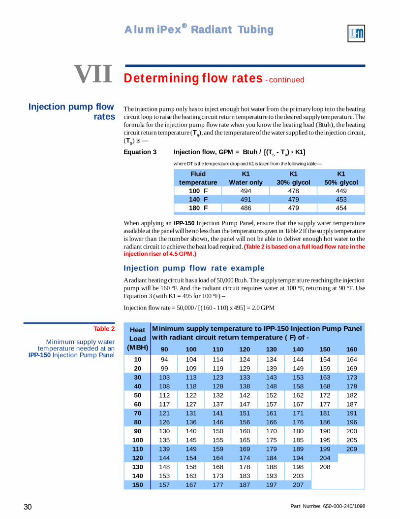
The injection pump only has to inject enough hot water from the primary loop into the heatingcircuit loop to raise the heating circuit return temperature to the desired supply temperature. Theformula for the injection pump flow rate when you know the heating load (Btuh), the heatingcircuit return temperature (TR), and the temperature of the water supplied to the injection circuit,(TS) is —
Equation 3 Injection flow, GPM = Btuh / [(TS - TR) x K1]
where DT is the temperature drop and K1 is taken from the following table —
When applying an IPP-150 Injection Pump Panel, ensure that the supply water temperatureavailable at the panel will be no less than the temperatures given in Table 2 If the supply temperatureis lower than the number shown, the panel will not be able to deliver enough hot water to theradiant circuit to achieve the heat load required. (Table 2 is based on a full load flow rate in theinjection riser of 4.5 GPM.)
Injection pump flow rate exampleA radiant heating circuit has a load of 50,000 Btuh. The supply temperature reaching the injectionpump will be 160 °F. And the radiant circuit requires water at 100 °F, returning at 90 °F. UseEquation 3 (with K1 = 495 for 100 °F) –
Injection flow rate = 50,000 / [(160 - 110) x 495] = 2.0 GPM
Table 2
Minimum supply watertemperature needed at an
IPP-150 Injection Pump Panel
������������������������������������������������������������������������������������������������������������������������������������������������������������������������������������������������������������������������������������������������������������������������������������������������������������������������������������������������������������������������������������������������������������������������������������������������������������������������������������������������������������������������������������������������������������������������������������������������������������������������������������������������������������������������������������������������������������������������������������������������������������������������������������������������������������������������������������������������������������������������������������������������������������������������������������������������������������������������������������������������������������������������������������������������������������������������������������������������������������������������������������������������������������������������������������
��������������������������������������������������������������������������������������������������������������������������������������������������������������������������������������������������������������������������������������������������������������������������������������������������������������������������������������������������������������������������������������������������������������������������������������������������������������������������������������������������������������������������������������������������������������������������������������������������������������������������������������������������������������������������������������������������������������������������������������������������������������������������������������������������������������������������������������������������������������������������������������������������������������������������������������������������������������������������������������������������������������������������������������������������������������������������������������������������������������������������������������������������������������������������������������������������������������������������������������������������������������������������������������������������������������������������������������������������������������������������������������������������������������������������������������������������������������������������������������������������������������������������������������������������������������������������������������������������������������������������������������������������������������������������������������������������������������������������������������������������������������������������������������������������������������������������������������������������������������������������������������������������������������������������������������������������������������������
90 100 110 120 130 140 150 160
10 94 104 114 124 134 144 154 16420 99 109 119 129 139 149 159 16930 103 113 123 133 143 153 163 17340 108 118 128 138 148 158 168 17850 112 122 132 142 152 162 172 18260 117 127 137 147 157 167 177 18770 121 131 141 151 161 171 181 19180 126 136 146 156 166 176 186 19690 130 140 150 160 170 180 190 200100 135 145 155 165 175 185 195 205110 139 149 159 169 179 189 199 209120 144 154 164 174 184 194 204130 148 158 168 178 188 198 208140 153 163 173 183 193 203150 157 167 177 187 197 207
HeatLoad
(MBH)
Minimum supply temperature to IPP-150 Injection Pump Panel with radiant circuit return temperature ( F) of -
Fluidtemperature
K1Water only
K130% glycol
K150% glycol
100 F 494 478 449140 F 491 479 453180 F 486 479 454
Part Number 650-000-240/1098 31
Controls ● Pumps ● Wiring — Installation Guide
Secondary circuitflow rates
Domestic water circuitsDetermine the flow rate for domestic water heating based on the recommended flow rate given bythe water heater manufacturer. Weil-McLain PLUS and GOLD Plus water heater literature includesthis information.
Baseboard circuitsThe flow rate for baseboard circuits is usually based on a 20 °F drop and can be calculated usingEquation 1 or read directly from Table 1.
Radiant circuitsDetermine the flow rate for the radiant loops using the AlumiPex Radiant Expert computerprogram or AlumiPex Design Guide (when available). As a rule of thumb, the flow rate per loopwill generally be 1 gpm or less for ½” tubing (higher for larger tubing).
The radiant circuit pump must deliver water to all of the circuits piped off of the manifold. So thetotal flow rate required from the pump is the sum of the flows in all connected circuits.
The flow rate may also be determined from the desired temperature drop and heat load, usingEquation 1 or Table 1.
Estimate the total flow for a radiant heating circuit by assuming some typical conditions —
• Temperature drop = 10 °F.
• Fluid in circuit is water (no glycol).
Radiant heating circuit flow rate exampleDesign conditions —
• Heat load = 15 Btuh per square foot.
• Loop length 300 feet of tubing.
• Tubing layout at 12 inches on center.
• Water only (no glycol).
• Temperature drop = 10 °F, from 100 °F to 90 °F.
Determine the estimated heat load for the loop —
• To determine how many square feet of floor the 300 feet of tubing will cover, consider that, at12 inch center to center tube spacing, there will be one linear foot of tubing to each square footof floor space. (For any other tubing spacing, divide 12 by the tube spacing in INCHES to findthe number of feet of tubing per square foot of floor. For example, 6 inch tube centers wouldrequire two linear feet of tubing per square foot of floor; i.e., 12/6 = 2.)
• Since there is 1 linear foot of tubing per square foot for this example of 12 inch centers, the 300foot tubing loop will cover 300 square feet of floor.
• The loading is 15 Btuh per square foot of floor, so the total load of the loop is 300 feet times15 Btuh per square foot, or 4,500 Btuh total.
Determine the estimated flow rate —
• Use Equation 1 (or Table 1) — Flow rate = 4,500/(495 x 10) = 0.91 GPM.
Part Number 650-000-240/109832
AlumiPAlumiPAlumiPAlumiPAlumiPeeeeexxxxx® ® ® ® ® Radiant TRadiant TRadiant TRadiant TRadiant Tubingubingubingubingubing
VIII Determining head loss
Equivalent length
Determine the pipe size for each circuit based on therequired flow for that circuit (in GPM), and the desiredhead loss. Avoid high head losses where possible. Highhead losses require more energy to pump the water,resulting in higher electrical costs and higher costs for thepumps. You can use the following method to determinehead losses in the system, boiler and water heater circuits.
• The head loss through a length of pipe is directlyproportional to its length.
• For any fitting or valve, there is an equivalentstraight length of pipe which would cause the samehead loss as the fitting or valve. This length of pipeis the equivalent length for that fitting. See Table 5for equivalent lengths of copper and threadedfittings.
• The Total Equivalent Length (TEL) for a circuit isthe sum of the length of the piping plus theequivalent lengths of all fittings in the circuit.
The equivalent length depends on pipe size. So begin byestimating the TEL as 1.5 times the length of the piping.In fact, for small systems, this estimate is usually adequatefor the head loss calculation. This is because the circuitlengths are relatively simple and short, and the head lossesare low. Example: if the circuit contains 130 feet of straightpipe, estimate the TEL as: TEL = 1.5 x 130 = 195 feet.
Head loss (series circuits)
Table 3 provides the means of calculating head losses inpiping circuits. It also provides recommended maximumand minimum flow rates for each size AlumiPex or coppertubing, or steel pipe. The maximum is intended tominimize noise and prevent erosion. The minimum isintended to assure adequate movement of air throughthe system.
Procedure —
Select a trial pipe size from Table 3 based on the designflow rate, in GPM, for the circuit. For any given copper
or steel pipe size, select the corresponding “a”, “b”, and“c” from the table. Use a value of c =1 except wheretemperature is closer to 100 °F or 180 °F than to 140 °F,where the appropriate value of c from the table may beused to adjust the pressure loss. Calculate the pipingcircuit head loss, in feet, as:
Equation 4 H = (TEL/100) x a x (GPM)b x c
Add to the piping head loss the head losses for boilers,water heaters, baseboard, heat exchangers or any othercomponents of this sort in the circuit. Refer to theinstructions or literature on these components for theestimated head loss.
TIPS • Estimate ¾" baseboard as if it werejust a straight length of ¾" pipe.
• For cast iron boilers — estimate a headloss of 1 to 2 feet for residentialboilers and 2 to 5 feet for commercialboilers.
If the head loss based on the trial pipe size is acceptable(usually between 5 and 15 feet), check the actual equivalentlength of the circuit using the pipe size you selected. Obtainthe equivalent lengths of all valves and fittings from Table5. If the TEL is different from your estimate, use the new,calculated, TEL in the head loss formula, Equation 4. Ifthe result is acceptable, use the required flow andcalculated head loss to select a pump. If not, increase (ordecrease) the pipe size as indicated and redo thecalculation.
Glycol/water systems
For systems filled with propylene glycol/water, first dothe calculations as if the system were filled with wateronly. Then apply the correction factors given in Table 4.You will see from the table that the flow rate for glycol/water must be from 14% to 16% higher than water onlyto achieve approximately the same heat transfer. The headloss for any give flow rate will be higher for the glycol/water mixture than for water only.
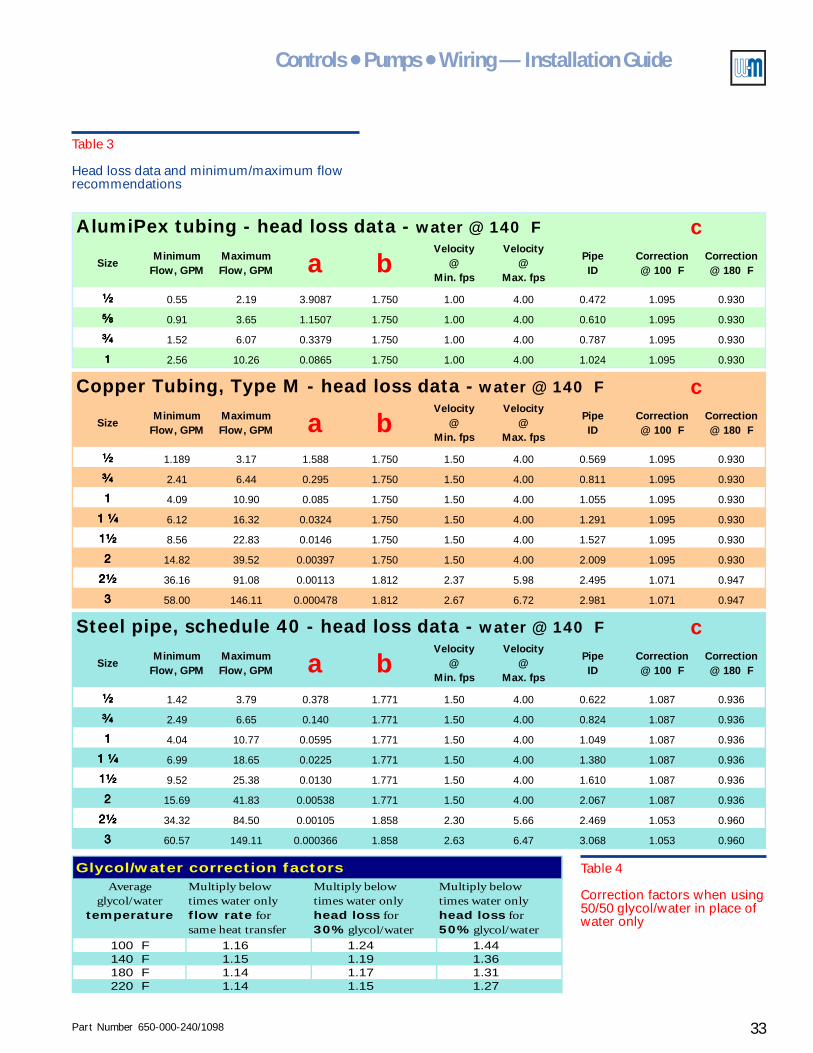
Part Number 650-000-240/1098 33
Controls ● Pumps ● Wiring — Installation Guide
Table 3
Head loss data and minimum/maximum flowrecommendations
Table 4
Correction factors when using50/50 glycol/water in place ofwater only
AlumiPex tubing - head loss data - water @ 140 F
¹⁄₂¹⁄₂¹⁄₂¹⁄₂ 0.55 2.19 3.9087 1.750 1.00 4.00 0.472 1.095 0.930
⁵⁄₈⁵⁄₈⁵⁄₈⁵⁄₈ 0.91 3.65 1.1507 1.750 1.00 4.00 0.610 1.095 0.930
³⁄₄³⁄₄³⁄₄³⁄₄ 1.52 6.07 0.3379 1.750 1.00 4.00 0.787 1.095 0.930
1111 2.56 10.26 0.0865 1.750 1.00 4.00 1.024 1.095 0.930
Copper Tubing, Type M - head loss data - water @ 140 F
¹⁄₂¹⁄₂¹⁄₂¹⁄₂ 1.189 3.17 1.588 1.750 1.50 4.00 0.569 1.095 0.930
³⁄₄³⁄₄³⁄₄³⁄₄ 2.41 6.44 0.295 1.750 1.50 4.00 0.811 1.095 0.930
1111 4.09 10.90 0.085 1.750 1.50 4.00 1.055 1.095 0.930
1 ¹⁄₄1 ¹⁄₄1 ¹⁄₄1 ¹⁄₄ 6.12 16.32 0.0324 1.750 1.50 4.00 1.291 1.095 0.930
1¹⁄₂1¹⁄₂1¹⁄₂1¹⁄₂ 8.56 22.83 0.0146 1.750 1.50 4.00 1.527 1.095 0.930
2222 14.82 39.52 0.00397 1.750 1.50 4.00 2.009 1.095 0.930
2¹⁄₂2¹⁄₂2¹⁄₂2¹⁄₂ 36.16 91.08 0.00113 1.812 2.37 5.98 2.495 1.071 0.947
3333 58.00 146.11 0.000478 1.812 2.67 6.72 2.981 1.071 0.947
Steel pipe, schedule 40 - head loss data - water @ 140 F
¹⁄₂¹⁄₂¹⁄₂¹⁄₂ 1.42 3.79 0.378 1.771 1.50 4.00 0.622 1.087 0.936
³⁄₄³⁄₄³⁄₄³⁄₄ 2.49 6.65 0.140 1.771 1.50 4.00 0.824 1.087 0.936
1111 4.04 10.77 0.0595 1.771 1.50 4.00 1.049 1.087 0.936
1 ¹⁄₄1 ¹⁄₄1 ¹⁄₄1 ¹⁄₄ 6.99 18.65 0.0225 1.771 1.50 4.00 1.380 1.087 0.936
1¹⁄₂1¹⁄₂1¹⁄₂1¹⁄₂ 9.52 25.38 0.0130 1.771 1.50 4.00 1.610 1.087 0.936
2222 15.69 41.83 0.00538 1.771 1.50 4.00 2.067 1.087 0.936
2¹⁄₂2¹⁄₂2¹⁄₂2¹⁄₂ 34.32 84.50 0.00105 1.858 2.30 5.66 2.469 1.053 0.960
3333 60.57 149.11 0.000366 1.858 2.63 6.47 3.068 1.053 0.960
c
c
PipeID
Correction@ 100 F
Correction@ 180 F
Velocity@
Min. fps
Velocity@
Max. fps
SizeMinimum
Flow, GPMMaximum Flow, GPM a b
Velocity@
Min. fps
Velocity@
Max. fps
Size
PipeID
Correction@ 100 F
Correction@ 180 F
Correction@ 180 F
c
PipeID
Correction@ 100 F
Minimum Flow, GPM
Maximum Flow, GPM a b
bVelocity
@Min. fps
Velocity@
Max. fpsSize
Minimum Flow, GPM
Maximum Flow, GPM a
Glycol/water correction factorsAverage
glycol/watertemperature
Multiply belowtimes water onlyflow rate forsame heat transfer
Multiply belowtimes water onlyhead loss for30% glycol/water
Multiply belowtimes water onlyhead loss for50% glycol/water
100 F 1.16 1.24 1.44140 F 1.15 1.19 1.36180 F 1.14 1.17 1.31220 F 1.14 1.15 1.27
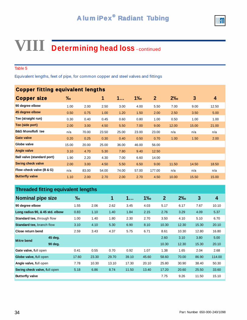
Part Number 650-000-240/109834
AlumiPAlumiPAlumiPAlumiPAlumiPeeeeexxxxx® ® ® ® ® Radiant TRadiant TRadiant TRadiant TRadiant Tubingubingubingubingubing
Table 5
Equivalent lengths, feet of pipe, for common copper and steel valves and fittings
Copper fitting equivalent lengthsCopper fitting equivalent lengthsCopper fitting equivalent lengthsCopper fitting equivalent lengths
Copper sizeCopper sizeCopper sizeCopper size ‰ 1 1… 1‰ 2 2‰ 3 490 degree elbow 1.00 2.00 2.50 3.00 4.00 5.50 7.00 9.00 12.50
45 degree elbow 0.50 0.75 1.00 1.20 1.50 2.00 2.50 3.50 5.00
Tee (straight run) 0.30 0.40 0.45 0.60 0.80 1.00 0.50 1.00 1.00
Tee (side port) 2.00 3.00 4.50 5.50 7.00 9.00 12.00 15.00 21.00
B&G Monoflofi tee n/a 70.00 23.50 25.00 23.00 23.00 n/a n/a n/a
Gate valve 0.20 0.25 0.30 0.40 0.50 0.70 1.00 1.50 2.00
Globe valve 15.00 20.00 25.00 36.00 46.00 56.00
Angle valve 3.10 4.70 5.30 7.80 9.40 12.50
Ball valve (standard port) 1.90 2.20 4.30 7.00 6.60 14.00
Swing check valve 2.00 3.00 4.50 5.50 6.50 9.00 11.50 14.50 18.50
Flow-check valve (B & G) n/a 83.00 54.00 74.00 57.00 177.00 n/a n/a n/a
Butterfly valve 1.10 2.00 2.70 2.00 2.70 4.50 10.00 15.50 15.00
Threaded fitting equivalent lengths
Nominal pipe size ‰ 1 1… 1‰ 2 2‰ 3 490 degree elbow 1.55 2.06 2.62 3.45 4.03 5.17 6.17 7.67 10.10
Long radius 90, & 45 std. elbow 0.83 1.10 1.40 1.84 2.15 2.76 3.29 4.09 5.37
Standard tee, through flow 1.00 1.40 1.80 2.30 2.70 3.50 4.10 5.10 6.70
Standard tee, branch flow 3.10 4.10 5.30 6.90 8.10 10.30 12.30 15.30 20.10
Close return bend 2.59 3.43 4.37 5.75 6.71 8.61 10.30 12.80 16.80
45 deg. 2.60 3.10 3.80 5.00
90 deg. 10.30 12.30 15.30 20.10
Gate valve, full open 0.41 0.55 0.70 0.92 1.07 1.38 1.65 2.04 2.68
Globe valve, full open 17.60 23.30 29.70 39.10 45.60 58.60 70.00 86.90 114.00
Angle valve, full open 7.78 10.30 13.10 17.30 20.10 25.80 30.90 38.40 50.30
Swing check valve, full open 5.18 6.86 8.74 11.50 13.40 17.20 20.60 25.50 33.60
Butterfly valve 7.75 9.26 11.50 15.10
Mitre bend
VIII Determining head loss - continued
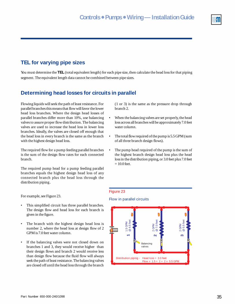
Part Number 650-000-240/1098 35
Controls ● Pumps ● Wiring — Installation Guide
Determining head losses for circuits in parallel
Flowing liquids will seek the path of least resistance. Forparallel branches this means that flow will favor the lowerhead loss branches. Where the design head losses ofparallel branches differ more than 10%, use balancingvalves to assure proper flow distribution. The balancingvalves are used to increase the head loss in lower lossbranches. Ideally, the valves are closed off enough thatthe head loss in every branch is the same as the branchwith the highest design head loss.
The required flow for a pump feeding parallel branchesis the sum of the design flow rates for each connectedbranch.
The required pump head for a pump feeding parallelbranches equals the highest design head loss of anyconnected branch plus the head loss through thedistribution piping .
For example, see Figure 23.
• This simplified circuit has three parallel branches.The design flow and head loss for each branch isgiven in the figure.
• The branch with the highest design head loss isnumber 2, where the head loss at design flow of 2GPM is 7.0 feet water column.
• If the balancing valves were not closed down onbranches 1 and 3, they would receive higher thantheir design flows and branch 2 would receive lessthan design flow because the fluid flow will alwaysseek the path of least resistance. The balancing valvesare closed off until the head loss through the branch
Figure 23
Flow in parallel circuits
1.5
GPM
@ 4
.5 fe
et
Distribution piping - Head loss = 3.0 feetFlow = 1.5 + 2 + 2 = 5.5 GPM
2 G
PM@
7.0
feet
2 G
PM@
5.5
feet
1 2 3
Balancingvalves
TEL for varying pipe sizes
You must determine the TEL (total equivalent length) for each pipe size, then calculate the head loss for that piping
segment. The equivalent length data cannot be combined between pipe sizes.
(1 or 3) is the same as the pressure drop throughbranch 2.
• When the balancing valves are set properly, the headloss across all branches will be approximately 7.0 feetwater column.
• The total flow required of the pump is 5.5 GPM (sumof all three branch design flows).
• The pump head required of the pump is the sum ofthe highest branch design head loss plus the headloss in the distribution piping, or 3.0 feet plus 7.0 feet= 10.0 feet.
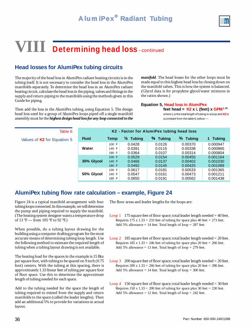
Part Number 650-000-240/109836
AlumiPAlumiPAlumiPAlumiPAlumiPeeeeexxxxx® ® ® ® ® Radiant TRadiant TRadiant TRadiant TRadiant Tubingubingubingubingubing
Head losses for AlumiPex tubing circuits
The majority of the head loss in AlumiPex radiant heating circuits is in thetubing itself. It is not necessary to consider the head loss in the AlumiPexmanifolds separately. To determine the head loss in an AlumiPex radiantheating circuit, calculate the head loss in the piping, valves and fittings in thesupply and return piping to the manifolds using the methods given in thisGuide for piping.
Then add the loss in the AlumiPex tubing, using Equation 5. The designhead loss used for a group of AlumiPex loops piped off a single manifoldassembly must be the highest design head loss for any loop connected to the
Figure 24 is a typical manifold arrangement with fourtubing loops connected. In this example, we will determinethe pump and piping required to supply the manifold.(The heating system designer wants a temperature dropof 13 °F — from 105 °F to 92 °F.)
When possible, do a tubing layout drawing for thebuilding using a computer drafting program for the mostaccurate means of determining tubing loop length. Usethe following method to estimate the required length oftubing when a tubing layout drawing is not available.
The heating load for the spaces in the example is 15 Btuper square foot, with tubing to be spaced on 9 inch (0.75foot) centers. With the tubing at this spacing, there isapproximately 1.33 linear feet of tubing per square footof floor space. Use this to determine the approximatelength of tubing needed for each space.
Add to the tubing needed for the space the length oftubing required to extend from the supply and returnmanifolds to the space (called the leader lengths). Thenadd an additional 5% to provide for variations in actuallayout.
VIII Determining head loss - continued
AlumiPex tubing flow rate calculation – example, Figure 24
manifold. The head losses for the other loops must bemade equal to this highest head loss by closing down onthe manifold valves. This is how the system is balanced.(Glycol data is for propylene glycol/water mixtures inthe ratios shown.)
Equation 5, Head loss in AlumiPexfeet head = K2 x L (feet) x GPM1.75
where L is the total length of tubing in a loop and K2 is
a constant from the table 6, below —
The floor areas and leader lengths for the loops are:
Loop 1 175 square feet of floor space; total leader length needed = 40 feet.Requires 175 x 1.33 = 233 feet of tubing for space plus 40 feet = 273 feet.Add 5% allowance = 14 feet. Total length of loop = 287 feet.
Loop 2 185 square feet of floor space; total leader length needed = 20 feet.Requires 185 x 1.33 = 246 feet of tubing for space plus 20 feet = 266 feet.Add 5% allowance = 13 feet. Total length of loop = 279 feet.
Loop 3 200 square feet of floor space; total leader length needed = 20 feet.Requires 200 x 1.33 = 266 feet of tubing for space plus 20 feet = 286 feet.Add 5% allowance = 14 feet. Total length of loop = 300 feet.
Loop 4 150 square feet of floor space; total leader length needed = 30 feetRequires 150 x 1.33 = 200 feet of tubing for space plus 30 feet = 230 feet.Add 5% allowance = 12 feet. Total length of loop = 242 feet.
Table 6
Values of K2 for Equation 5 Fluid Temp ¹⁄₂¹⁄₂¹⁄₂¹⁄₂ Tubing ⁵⁄₈⁵⁄₈⁵⁄₈⁵⁄₈ Tubing ³⁄₄³⁄₄³⁄₄³⁄₄ Tubing 1 Tubing100 F 0.0428 0.0126 0.00370 0.000947140 F 0.0391 0.0115 0.00338 0.000865180 F 0.0364 0.0107 0.00314 0.000804100 F 0.0529 0.0154 0.00455 0.001164140 F 0.0466 0.0137 0.00402 0.001030180 F 0.0492 0.0145 0.00425 0.001089100 F 0.0617 0.0181 0.00533 0.001365140 F 0.0547 0.0161 0.00473 0.001211180 F 0.0650 0.0191 0.00562 0.001438
50% Glycol
K2 - Factor for AlumiPex tubing head loss
Water
30% Glycol
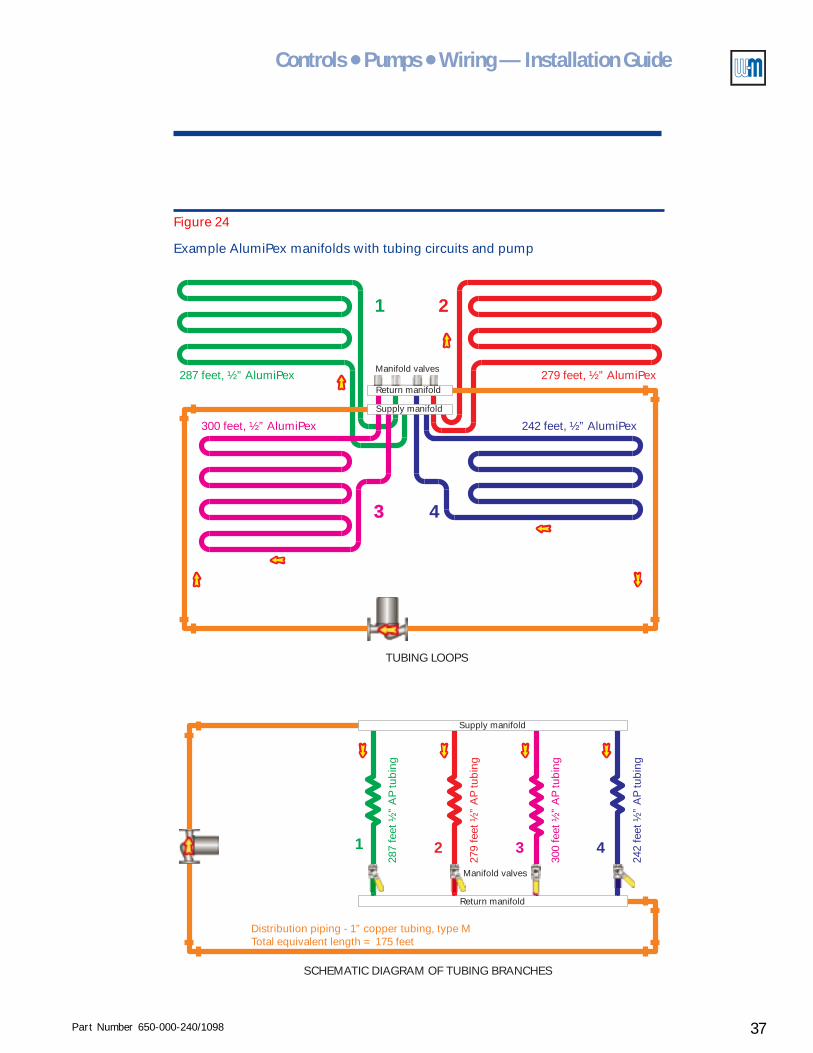
Part Number 650-000-240/1098 37
Controls ● Pumps ● Wiring — Installation Guide
287
feet
½”
AP
tubi
ng
279
feet
½”
AP
tubi
ng
300
feet
½”
AP
tubi
ng
242
feet
½”
AP
tubi
ng
Distribution piping - 1” copper tubing, type MTotal equivalent length = 175 feet
1 2 3 4
Manifold valves
Manifold valves
Supply manifold
Supply manifold
Return manifold
Return manifold
1 2
3 4
287 feet, ½” AlumiPex 279 feet, ½” AlumiPex
300 feet, ½” AlumiPex 242 feet, ½” AlumiPex
TUBING LOOPS
SCHEMATIC DIAGRAM OF TUBING BRANCHES
Figure 24
Example AlumiPex manifolds with tubing circuits and pump
Part Number 650-000-240/109838
AlumiPAlumiPAlumiPAlumiPAlumiPeeeeexxxxx® ® ® ® ® Radiant TRadiant TRadiant TRadiant TRadiant Tubingubingubingubingubing
Now determine the flow rate required for each of the loops.
• The heating system will be filled with water (no glycol).• The temperature drop is to be 13 °F (from 105 °F to 92 °F).• Calculate the heat load for each loop by multiplying 15 Btuh per square foot by the area (in
square feet) heated by the loop.• Apply Equation 1 to calculate the flow rate in each loop.
For the example in Figure 24:
• Loop 1 Heat load = 15 x 175 = 2625 Btuh; Flow rate = 2625/(494 x 13) = 0.41 GPM• Loop 2 Heat load = 15 x 185 = 2775 Btuh; Flow rate = 2775/(494 x 13) = 0.43 GPM• Loop 3 Heat load = 15 x 200 = 3000 Btuh; Flow rate = 3000/(494 x 13) = 0.47 GPM• Loop 4 Heat load = 15 x 150 = 2250 Btuh; Flow rate = 2250/(494 x 13) = 0.35 GPM• Total Total flow rate for pump = 0.41 + 0.43 + 0.47 + 0.35 = 1.66 GPM.
Determine the head loss for each AlumiPex tubing loop at design flow rate using Equation 5 (usingthe K2 value for ½” tubing and 100 °F, since the water ranges from 105 °F to 92 °F). For theseconditions, the K2 value is 0.0428.
• Loop 1 Head loss = .0428 x 287 x 0.411.75 = 2.58 feet• Loop 2 Head loss = .0428 x 279 x 0.431.75 = 2.73 feet• Loop 3 Head loss = .0428 x 300 x 0.471.75 = 3.43 feet (highest head loss)• Loop 4 Head loss = .0428 x 287 x 0.351.75 = 1.96 feet• Note that the manifold valves would have to be partially closed on loops 1, 2 and 4 to cause
the head losses for these loops to match that of loop 3, the branch with the highest loss.
Determine the pipe size and head loss in the distribution piping.
• The flow in the distibution piping will be 1.66 GPM. Find a pipe size in Table 3 which is suitablefor this flow. The flow is within the range of ½” copper tubing, so select this as the pipe size.
• The example system has (12) 90-degree elbows (not shown) and (2) gate valves plus 150linear feet of piping. Find the equivalent lengths of these fittings for ½” copper from Table 5(1.00 feet per elbow; 0.20 feet per gate valve). The TEL for the distribution piping is –
TEL = 150 + (12 x 1.00) + (2 x 0.20) = 162 feet.• The head loss for the distribution piping using ½” copper tubing, at 1.66 GPM would be
(from Table 3) –Head loss = (162/100) x 1.588 x 1.661.75 = 6.25 feet.
Determine total required head for the pump —
• The highest loop head loss for any of the AlumiPex loops is 3.43 feet.• Add this to the distribution piping loss of 6.25 feet, for a toal head loss of 9.68 feet.
Solution — Select a pump capable of 1.66 GPM at a head loss of 9.68 feet.
AlumiPex tubingflow rate calculation
– example, Figure 24,continued
VIII Determining head loss - continued
Note – If the loading required of a tubing loop requires too high a flow rate (or pressure drop), considerincreasing the tube diameter, provided the flow rate in the tubing is within the recommended flowrate range (between the minimum and maximum recommended flow rates).
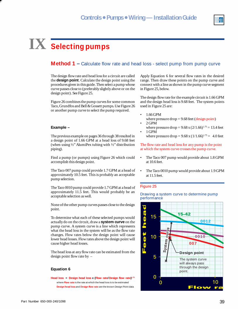
Part Number 650-000-240/1098 39
Controls ● Pumps ● Wiring — Installation Guide
IX Selecting pumps
The design flow rate and head loss for a circuit are calledthe design point. Calculate the design point using theprocedures given in this guide. Then select a pump whosecurve passes close to (preferably slightly above or on thedesign point). See Figure 25.
Figure 26 combines the pump curves for some commonTaco, Grundfos and Bell & Gossett pumps. Use Figure 26or another pump curve to select the pump required.
Example –
The previous example on pages 36 through 38 resulted ina design point of 1.66 GPM at a head loss of 9.68 feet(when using ½” AlumiPex tubing with ½” distributionpiping).
Find a pump (or pumps) using Figure 26 which couldaccomplish this design point.
The Taco 007 pump could provide 1.7 GPM at a head ofapproximately 10.5 feet. This is probably an acceptablepump selection.
The Taco 0010 pump could provide 1.7 GPM at a head ofapproximately 11.5 feet. This would probably be anacceptable selection as well.
None of the other pump curves passes close to the designpoint.
To determine what each of these selected pumps wouldactually do on the circuit, draw a system curve on thepump curve. A system curve is a line which representswhat the head loss in the system will be as the flow ratechanges. Flow rates below the design point will causelower head losses. Flow rates above the design point willcause higher head losses.
The head loss at any flow rate can be estimated from thedesign point flow rate by –
Equation 6
Head loss = Design head loss x (Flow rate/Design flow rate)1.75
where Flow rate is the rate at which the head loss is to be estimated
Design head loss and Design flow rate are the known Design Point data
Method 1 – Calculate flow rate and head loss - select pump from pump curve
Design pointSys
tem
curv
eS
yste
m c
urv
e
The system curvewill always passthrough the designpoint.
0010
0012
007
Figure 25
Drawing a system curve to determine pumpperformance
Apply Equation 6 for several flow rates in the desiredrange. Then draw these points on the pump curve andconnect with a line as shown in the pump curve segmentin Figure 25, below.
The design flow rate for the example circuit is 1.66 GPMand the design head loss is 9.68 feet. The system pointsused in Figure 25 are:
• 1.66 GPMwhere pressure drop = 9.68 feet (design point)
• 2 GPMwhere pressure drop = 9.68 x (2/1.66)1.75 = 13.4 feet
• 1 GPMwhere pressure drop = 9.68 x (1/1.66)1.75 = 4.0 feet
The flow rate and head loss for any pump is the pointat which the system curve crosses the pump curve.
• The Taco 007 pump would provide about 1.8 GPMat 10.6 feet.
• The Taco 0010 pump would provide about 1.9 GPMat 11.5 feet.
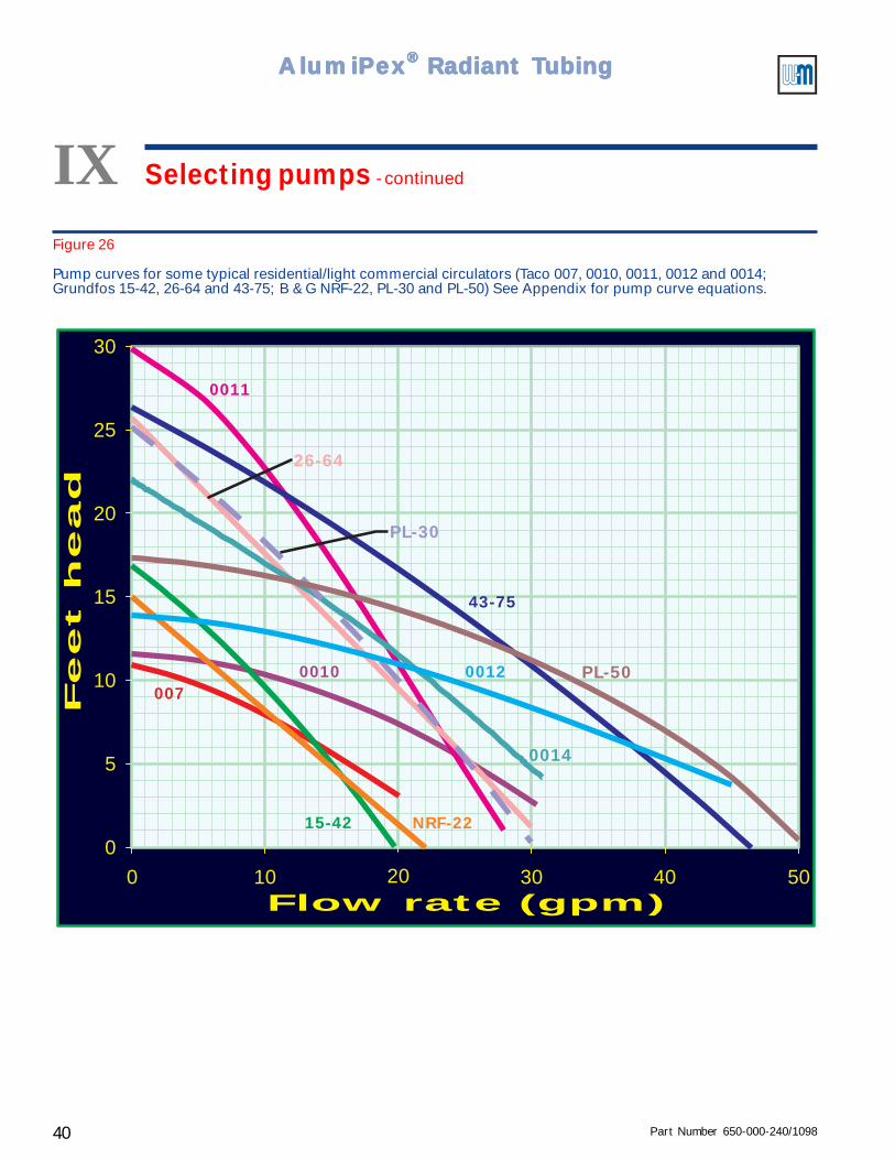
Part Number 650-000-240/109840
AlumiPAlumiPAlumiPAlumiPAlumiPeeeeexxxxx® ® ® ® ® Radiant TRadiant TRadiant TRadiant TRadiant Tubingubingubingubingubing
IX Selecting pumps - continued
Figure 26
Pump curves for some typical residential/light commercial circulators (Taco 007, 0010, 0011, 0012 and 0014;Grundfos 15-42, 26-64 and 43-75; B & G NRF-22, PL-30 and PL-50) See Appendix for pump curve equations.
0
5
10
15
20
25
30
0 10 20Flow rate (gpm)
Feet head
30 40 50
007
NRF-2215-42
0010 0012
43-75
0011
PL-50
0014
PL-30
26-64
Part Number 650-000-240/1098 41
Controls ● Pumps ● Wiring — Installation Guide
Figures 27 through 30 are quick selector curves forselecting pumps based on a known flow rate and circuitlength.
The pumps included in these curves are —
• Taco 007, 0010, 0011, 0012, 0014.
• Grundfos 15-42, 26-64, 43-75.
• Bell & Gossett NRF-22, PL-30, PL-50.
• (See Appendix for pump curve equations.)
Use these curves only when the pipe diameter is the samethroughout the circuit being analyzed.
This method will work well for determining both pipesize and pump selection for primary circuits andbaseboard heating secondary circuits.
To select a pump using this method –
• Calculate the required flow rate based on the heatingload (Btuh) and the desired temperature drop usingEquation 1: GPM = Btuh/(494 x DT).
• Select a trial pipe size using Table 3 — that is, a pipesize for which the flow rate falls between the minimumand maximum recommended.
• Determine the linear feet of piping expected for thecircuit.
• Multiply this number by 1.5. The result is yourapproximate TEL (total equivalent length) for thecircuit.
• Select the Figure from Figures 27 through 30 for thepipe size you have selected.
• Select the pump which can deliver the flow rate andTEL you need.
Method 2 – Calculate flow rate and select pump from quick selector curves
• If you can't find a good pump selection, try anotherpipe size.
• You can refine and verify your selection by calculatingthe actual TEL for your circuit using the equivalentlength data in this Guide.
Example:
• A circuit with 300 linear feet of piping; heating load200,000 Btuh; using water from 180 °F to 160 °F.
• Estimate the TEL at 1.5 times 300, or 450 feet.
• Using Equation 1, the required flow rate for a 20 °Fdrop would be:
Flow rate = 200000/(494 x 20) = 20.2 GPM
• From Table 3, either 1½” or 2” copper pipe would beusable (though the pressure drop would be higher in1½” pipe). Use 1½” copper pipe for the trial size.
• From Figure 30, with 1½" copper pipe at a TEL of450 feet, a Taco 0011 or 0014 would deliver about19.5 GPM at 450 feet TEL. Or a B & G model PL-50would deliver about 21.3 GPM.
• At 19.5 GPM, the temperature drop would be (fromEquation 2) —
200000/(494 x 19.5) = 20.8 °F. So the Taco 0011 or0014 would probably be an adequate selection.
• Note, from Figure 30, that a model 0010, 0011, PL-30or 26-64 would be the likely choices if the pipe sizewere increased to 2” copper pipe. These pumps woulddeliver about 25 GPM.
• Verify the pump selection by doing a completecalculation of the TEL, using the data in this Guide.
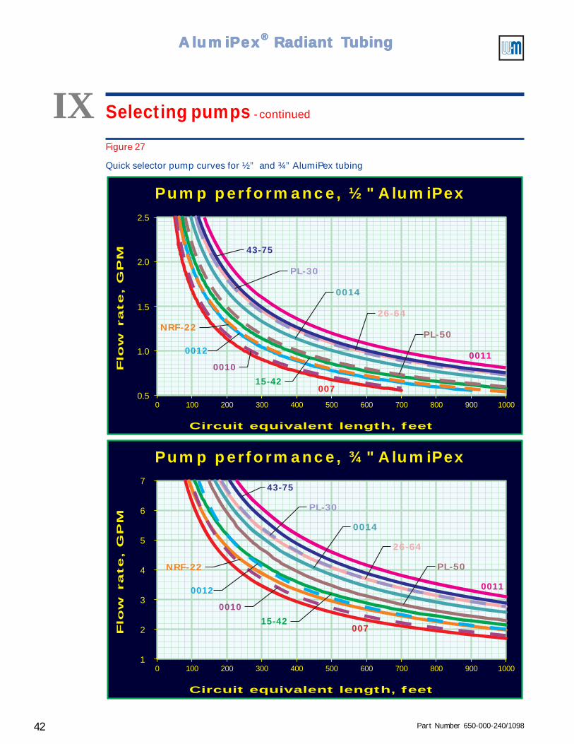
Part Number 650-000-240/109842
AlumiPAlumiPAlumiPAlumiPAlumiPeeeeexxxxx® ® ® ® ® Radiant TRadiant TRadiant TRadiant TRadiant Tubingubingubingubingubing
Figure 27
Quick selector pump curves for ½” and ¾” AlumiPex tubing
0 100 200 300 400 500 600 700 800 900 10000.5
1.0
1.5
2.0
2.5
Flo
w r
ate, G
PM
Pump performance, ½" AlumiPex
Circuit equivalent length, feet
007
001000110012
43-75
15-42
PL-30
PL-50
0014
26-64
NRF-22
0 100 200 300 400 500 600 700 800 900 10001
2
3
4
5
6
7
Flo
w r
ate, G
PM
Circuit equivalent length, feet
Pump performance, ¾" AlumiPex
007
0010
00110012
43-75
15-42
PL-30
PL-50
0014
26-64
NRF-22
IX Selecting pumps - continued
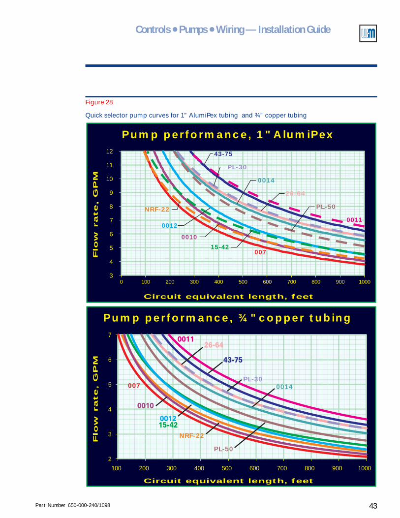
Part Number 650-000-240/1098 43
Controls ● Pumps ● Wiring — Installation Guide
0 100 200 300 400 500 600 700 800 900 10003
4
5
6
7
8
9
10
12
11
Flo
w r
ate, G
PM
Circuit equivalent length, feet
Pump performance, 1" AlumiPex
0011
43-75
PL-30
PL-50
0014
26-64
007
0010
0012
15-42
NRF-22
Flo
w r
ate, G
PM
Circuit equivalent length, feet
Pump performance, ¾" copper tubing
2
3
4
5
6
7
100 200 300 400 500 600 700 800 900 1000
PL-50
0014
NRF-22
PL-30007
Figure 28
Quick selector pump curves for 1” AlumiPex tubing and ¾” copper tubing
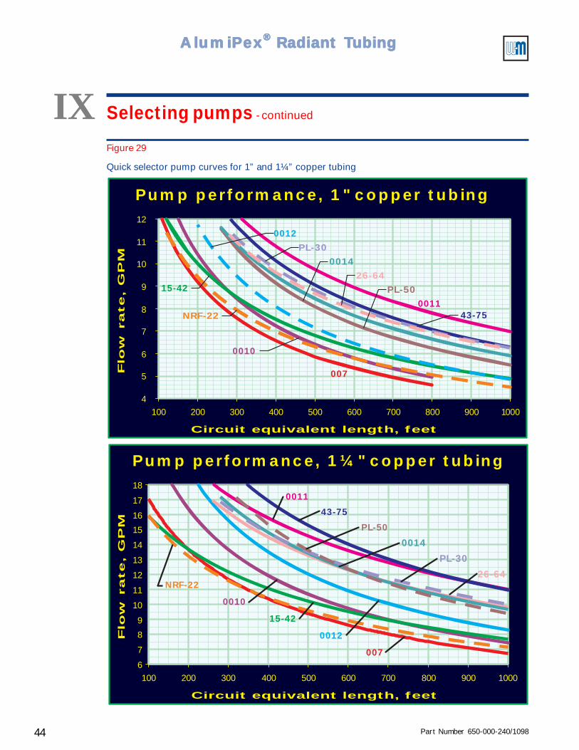
Part Number 650-000-240/109844
AlumiPAlumiPAlumiPAlumiPAlumiPeeeeexxxxx® ® ® ® ® Radiant TRadiant TRadiant TRadiant TRadiant Tubingubingubingubingubing
Figure 29
Quick selector pump curves for 1” and 1¼” copper tubing
IX Selecting pumps - continued
4
5
6
7
8
9
10
11
12
100 200 300 400 500 600 700 800 900 1000
Flo
w r
ate, G
PM
Circuit equivalent length, feet
Pump performance, 1" copper tubing
15-42
NRF-22
007
0010
0011
0012
43-75
PL-30
PL-50
0014
26-64
Flo
w r
ate, G
PM
Circuit equivalent length, feet
Pump performance, 1¼" copper tubing
100 200 300 400 500 600 700 800 900 10006
7
8
9
10
11
12
13
14
15
16
17
18
007
0010
NRF-22
15-42
0012
0011
43-75
PL-50
0014
PL-30
26-64
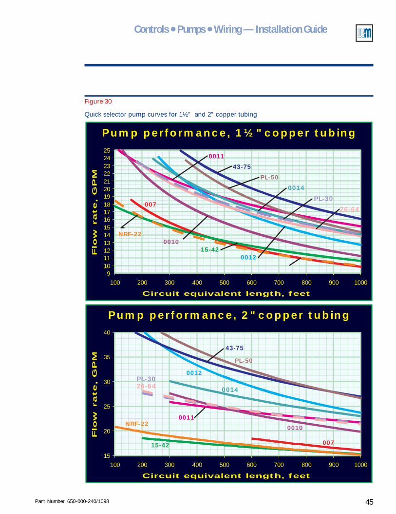
Part Number 650-000-240/1098 45
Controls ● Pumps ● Wiring — Installation Guide
Flo
w r
ate, G
PM
Circuit equivalent length, feet
Pump performance, 1½" copper tubing
100 200 300 400 500 600 700 800 900 10009
10111213141516171819202122232425
007
0010NRF-22
15-420012
0011
43-75
PL-50
0014
PL-30
26-64
Flo
w r
ate, G
PM
Circuit equivalent length, feet
Pump performance, 2" copper tubing
100 200 300 400 500 600 700 800 900 1000
40
15
20
25
30
35
007
0011NRF-22
15-42
0010
0012
43-75
PL-50
0014
PL-3026-64
Figure 30
Quick selector pump curves for 1½” and 2” copper tubing
Part Number 650-000-240/109846
AlumiPAlumiPAlumiPAlumiPAlumiPeeeeexxxxx® ® ® ® ® Radiant TRadiant TRadiant TRadiant TRadiant Tubingubingubingubingubing
X Piping radiant circuits
Higher temperature radiant circuits
The piping (and associated wiring) suggestions shown in the following pages
all provide some means of protecting the boiler from cold return water
temperatures. The special case of system CP-1 — adding a small radiant zone
to a baseboard heating system — does not provide return water temperature
regulation because the radiant zone is too small to cause unusually low return
temperatures.
Some radiant heating applications operate with temperatures similar to those
of finned tube baseboard systems – for example, where the tubing is suspended
in the joist bay, or for suspended floor applications with the tubing underneath
and carpet on the floor. In these cases, the supply temperature at design
conditions will often be 160 °F or higher.
For those suspended floor radiant heating applications requiring at least 160
°F supply water, the return water temperatures will be similar to finned tube
baseboard applications. Consequently, it would not usually be necessary to
provide return water temperature protection for the boiler in such
applications. These radiant heating zones can be installed as secondary circuits
directly connected to the primary, without using a mixing valve or injection
mixing system to protect the boiler.
The following sections provide suggested piping and wiring methods for
radiant heating systems and for hybrid systems which provide domestic
water and/or baseboard heating as well as radiant heating.
The radiant heating circuits illustrated in this Guide are all shown with injection
mixing. But you can substitute dual temperature mixing valves for the injection
mixing arrangement in all of the examples given. Follow the piping guidelines
for dual mixing valve circuits given in previous section II, Piping and control
methods, Method 2 - Dual three-way valves.
Overview
Part Number 650-000-240/1098 47
Controls ● Pumps ● Wiring — Installation Guide
Alternative piping configurations
Most of the examples shown in this Guide utilize Weil-McLain IPP Injection Pump Panels and IPC
Injection Pump Controls. You will also find that we have given an alternative piping arrangement
for example systems CP-2 through CP-12 in Radiant heating system examples.
This Guide does not exclude other engineered systems that protect the system and the boiler (as
directed by the boiler manufacturer). We have concentrated on injection mixing and mixing valve
piping configurations in order to provide you with as complete an analysis and guide for their
applications as possible. Weil-McLain can provide you with supplementary materials for other
specific piping alternatives. Also refer to the boiler (heating source) manufacturer’s instruction
manuals and design information for their requirements and specific suggestions.
Pump location
In the following system examples, the primary circuit pump is shown mounted in the supply
piping, with the expansion tank and air separator on the inlet side of the pump (with the exception
of GV boiler systems). This is the preferred location for all pumps, and the only recommended
location for commercial system pumps.
Many packaged residential boilers are supplied with the pump on the return line to the boiler.
This is acceptable for residential applications and for multiple boiler systems using residential
packaged boilers. See the Caution statement below regarding location of the expansion tank and
fill connection.
Always connect the fill line at the expansion tank.
Locate the expansion tank (diaphragm or bladder type) on the inlet side of
the pump, even if the pump is mounted on the boiler return line.
When using a compression tank (expansion tank in which air is exposed to
the water), mount the compression tank and fill connection in the supply
piping, regardless of the location of the pump.
Failure to follow these guidelines could result in damage to the boiler and
system components.
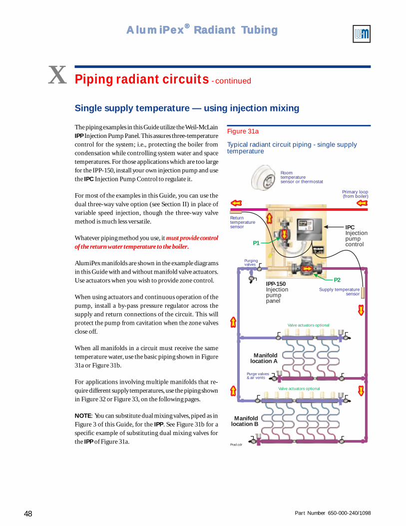
Part Number 650-000-240/109848
AlumiPAlumiPAlumiPAlumiPAlumiPeeeeexxxxx® ® ® ® ® Radiant TRadiant TRadiant TRadiant TRadiant Tubingubingubingubingubing
P2
P1
IPP-150Injectionpumppanel
IPCInjectionpumpcontrol
Manifoldlocation A
Manifoldlocation B
Returntemperaturesensor
Primary loop(from boiler)
Roomtemperaturesensor or thermostat
Purge valves& air vents
Supply temperaturesensor
Valve actuators optional
Valve actuators optional
Purgingvalves
Prad.cdr
Figure 31a
Typical radiant circuit piping - single supplytemperature
Single supply temperature — using injection mixing
The piping examples in this Guide utilize the Weil-McLainIPP Injection Pump Panel. This assures three-temperaturecontrol for the system; i.e., protecting the boiler fromcondensation while controlling system water and spacetemperatures. For those applications which are too largefor the IPP-150, install your own injection pump and usethe IPC Injection Pump Control to regulate it.
For most of the examples in this Guide, you can use thedual three-way valve option (see Section II) in place ofvariable speed injection, though the three-way valvemethod is much less versatile.
Whatever piping method you use, it must provide controlof the return water temperature to the boiler.
AlumiPex manifolds are shown in the example diagramsin this Guide with and without manifold valve actuators.Use actuators when you wish to provide zone control.
When using actuators and continuous operation of thepump, install a by-pass pressure regulator across thesupply and return connections of the circuit. This willprotect the pump from cavitation when the zone valvesclose off.
When all manifolds in a circuit must receive the sametemperature water, use the basic piping shown in Figure31a or Figure 31b.
For applications involving multiple manifolds that re-quire different supply temperatures, use the piping shownin Figure 32 or Figure 33, on the following pages.
NOTE: You can substitute dual mixing valves, piped as inFigure 3 of this Guide, for the IPP. See Figure 31b for aspecific example of substituting dual mixing valves forthe IPP of Figure 31a.
X Piping radiant circuits - continued
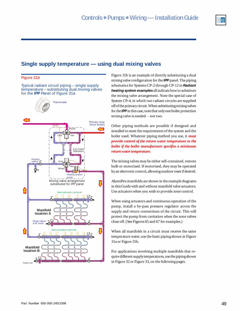
Part Number 650-000-240/1098 49
Controls ● Pumps ● Wiring — Installation Guide
Manifoldlocation A
Manifoldlocation B
Primary loop(from boiler)
Thermostat
Purge valves& air vents
Valve actuators optional
Valve actuators optional
Purgingvalves
Pradmv.cdr
Mixing valve arrangementsubstituted for IPP panel
Heating systempump
Hot
Hot
Mixed
Mixed
Cold
2 to 4 pipediameters
Cold
Figure 31b
Typical radiant circuit piping – single supplytemperature – substituting dual mixing valvesfor the IPP Panel of Figure 31a
Single supply temperature — using dual mixing valves
Figure 31b is an example of directly substituting a dualmixing valve configuration for the IPP panel. The pipingschematics for Systems CP-2 through CP-12 in Radiantheating system examples all indicate how to substitutethe mixing valve arrangement. Note the special case ofSystem CP-4, in which two radiant circuits are suppliedoff of the primary circuit. When substituting mixing valvesfor the IPP in this case, note that only one boiler protectionmixing valve is needed – not two.
Other piping methods are possible if designed andinstalled to meet the requirements of the system and theboiler used. Whatever piping method you use, it mustprovide control of the return water temperature to theboiler if the boiler manufacturer specifies a minimumreturn water temperature.
The mixing valves may be either self-contained, remotebulb or motorized. If motorized, they may be operatedby an electronic control, allowing outdoor reset if desired.
AlumiPex manifolds are shown in the example diagramsin this Guide with and without manifold valve actuators.Use actuators when you wish to provide zone control.
When using actuators and continuous operation of thepump, install a by-pass pressure regulator across thesupply and return connections of the circuit. This willprotect the pump from cavitation when the zone valvesclose off. (See Figures 65 and 67 for examples.)
When all manifolds in a circuit must receive the sametemperature water, use the basic piping shown in Figure31a or Figure 31b.
For applications involving multiple manifolds that re-quire different supply temperatures, use the piping shownin Figure 32 or Figure 33, on the following pages.
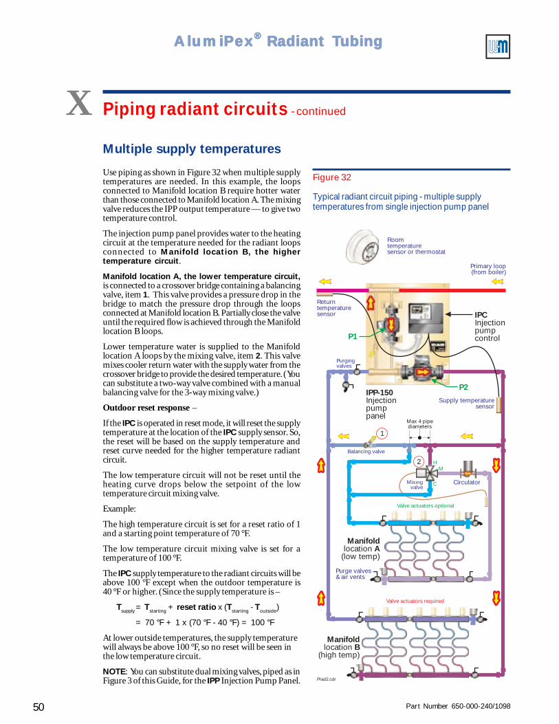
Part Number 650-000-240/109850
AlumiPAlumiPAlumiPAlumiPAlumiPeeeeexxxxx® ® ® ® ® Radiant TRadiant TRadiant TRadiant TRadiant Tubingubingubingubingubing
P2
P1
IPP-150Injectionpumppanel
IPCInjectionpumpcontrol
ManifoldAlocation
(low temp)
Returntemperaturesensor
Supply temperaturesensor
Max 4 pipediameters
Balancing valve
Mixingvalve
H
C
M
Circulator
1
Valve actuators optional
Valve actuators required
ManifoldBlocation
(high temp)
Purge valves& air vents
2
Purgingvalves
Roomtemperaturesensor or thermostat
Prad2.cdr
Primary loop(from boiler)
Figure 32
Typical radiant circuit piping - multiple supplytemperatures from single injection pump panel
Multiple supply temperatures
Use piping as shown in Figure 32 when multiple supplytemperatures are needed. In this example, the loopsconnected to Manifold location B require hotter waterthan those connected to Manifold location A. The mixingvalve reduces the IPP output temperature — to give twotemperature control.
The injection pump panel provides water to the heatingcircuit at the temperature needed for the radiant loopsconnected to Manifold location B, the highertemperature circuit.
Manifold location A, the lower temperature circuit,is connected to a crossover bridge containing a balancingvalve, item 1. This valve provides a pressure drop in thebridge to match the pressure drop through the loopsconnected at Manifold location B. Partially close the valveuntil the required flow is achieved through the Manifoldlocation B loops.
Lower temperature water is supplied to the Manifoldlocation A loops by the mixing valve, item 2. This valvemixes cooler return water with the supply water from thecrossover bridge to provide the desired temperature. (Youcan substitute a two-way valve combined with a manualbalancing valve for the 3-way mixing valve.)
Outdoor reset response –
If the IPC is operated in reset mode, it will reset the supplytemperature at the location of the IPC supply sensor. So,the reset will be based on the supply temperature andreset curve needed for the higher temperature radiantcircuit.
The low temperature circuit will not be reset until theheating curve drops below the setpoint of the lowtemperature circuit mixing valve.
Example:
The high temperature circuit is set for a reset ratio of 1and a starting point temperature of 70 °F.
The low temperature circuit mixing valve is set for atemperature of 100 °F.
The IPC supply temperature to the radiant circuits will beabove 100 °F except when the outdoor temperature is40 °F or higher. (Since the supply temperature is –
Tsupply= Tstarting + reset ratio x (Tstarting - Toutside)
= 70 °F + 1 x (70 °F - 40 °F) = 100 °F
At lower outside temperatures, the supply temperaturewill always be above 100 °F, so no reset will be seen inthe low temperature circuit.
NOTE: You can substitute dual mixing valves, piped as inFigure 3 of this Guide, for the IPP Injection Pump Panel.
X Piping radiant circuits - continued
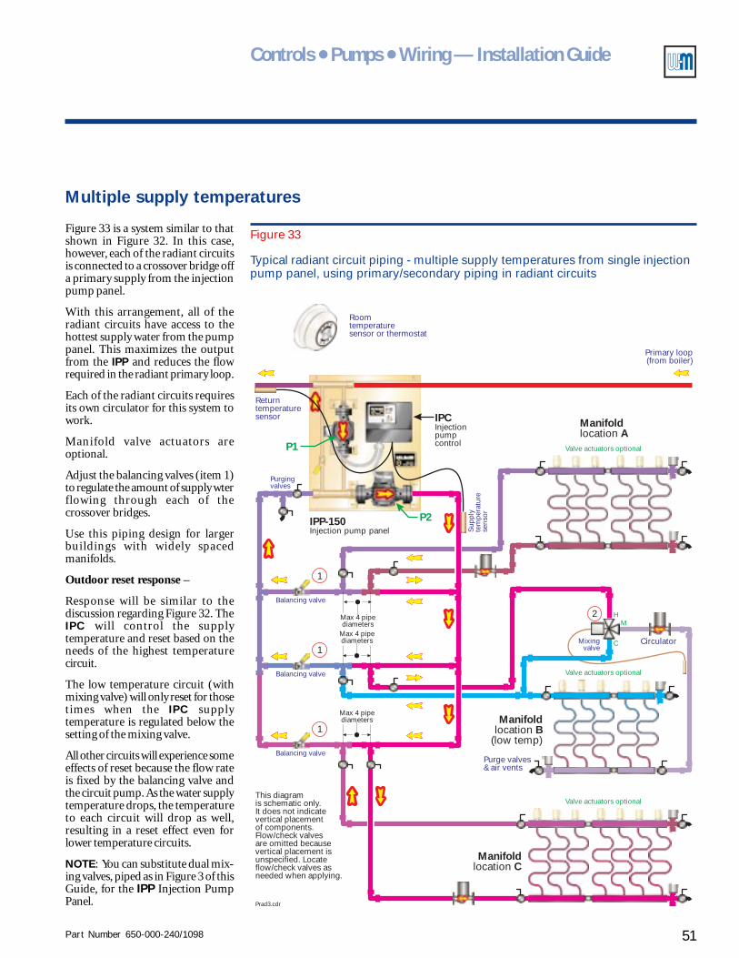
Part Number 650-000-240/1098 51
Controls ● Pumps ● Wiring — Installation Guide
P2
P1
IPP-150Injection pump panel
IPCInjectionpumpcontrol
This diagramis schematic only.It does not indicatevertical placementof components.Flow/check valvesare omitted becausevertical placement isunspecified. Locateflow/check valves asneeded when applying.
ManifoldBlocation
(low temp)
Returntemperaturesensor
Sup
ply
tem
pera
ture
sens
or
Balancing valve
Mixingvalve
H
C
M
Circulator
Max 4 pipediameters
1
Balancing valve
Max 4 pipediameters
1
Balancing valve
Max 4 pipediameters
1
Valve actuators optional
Valve actuators optional
Valve actuators optional
ManifoldClocation
ManifoldAlocation
Purge valves& air vents
2
Purgingvalves
Roomtemperaturesensor or thermostat
Prad3.cdr
Primary loop(from boiler)
Figure 33
Typical radiant circuit piping - multiple supply temperatures from single injectionpump panel, using primary/secondary piping in radiant circuits
Multiple supply temperatures
Figure 33 is a system similar to thatshown in Figure 32. In this case,however, each of the radiant circuitsis connected to a crossover bridge offa primary supply from the injectionpump panel.
With this arrangement, all of theradiant circuits have access to thehottest supply water from the pumppanel. This maximizes the outputfrom the IPP and reduces the flowrequired in the radiant primary loop.
Each of the radiant circuits requiresits own circulator for this system towork.
Manifold valve actuators areoptional.
Adjust the balancing valves (item 1)to regulate the amount of supply wterflowing through each of thecrossover bridges.
Use this piping design for largerbuildings with widely spacedmanifolds.
Outdoor reset response –
Response will be similar to thediscussion regarding Figure 32. TheIPC will control the supplytemperature and reset based on theneeds of the highest temperaturecircuit.
The low temperature circuit (withmixing valve) will only reset for thosetimes when the IPC supplytemperature is regulated below thesetting of the mixing valve.
All other circuits will experience someeffects of reset because the flow rateis fixed by the balancing valve andthe circuit pump. As the water supplytemperature drops, the temperatureto each circuit will drop as well,resulting in a reset effect even forlower temperature circuits.
NOTE: You can substitute dual mix-ing valves, piped as in Figure 3 of thisGuide, for the IPP Injection PumpPanel.
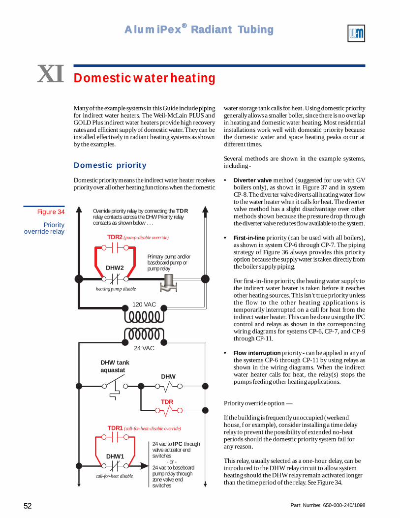
Part Number 650-000-240/109852
AlumiPAlumiPAlumiPAlumiPAlumiPeeeeexxxxx® ® ® ® ® Radiant TRadiant TRadiant TRadiant TRadiant Tubingubingubingubingubing
XI Domestic water heating
Many of the example systems in this Guide include pipingfor indirect water heaters. The Weil-McLain PLUS andGOLD Plus indirect water heaters provide high recoveryrates and efficient supply of domestic water. They can beinstalled effectively in radiant heating systems as shownby the examples.
Domestic priority
Domestic priority means the indirect water heater receivespriority over all other heating functions when the domestic
120 VAC
24 VAC
DHW tankaquastat
DHW
TDR
24 vac to throughvalve actuator endswitches
- or -24 vac to baseboardpump relay throughzone valve endswitches
IPC
Primary pump and/orbaseboard pump orpump relay
Override priority relay by connecting therelay contacts across the DHW Priority relaycontacts as shown below . . .
TDR
DHW1
TDR1 (call-for-heat-disable override)
TDR2 (pump-disable override)
DHW2
call-for-heat disable
heating pump disable
Figure 34
Priorityoverride relay
water storage tank calls for heat. Using domestic prioritygenerally allows a smaller boiler, since there is no overlapin heating and domestic water heating. Most residentialinstallations work well with domestic priority becausethe domestic water and space heating peaks occur atdifferent times.
Several methods are shown in the example systems,including -
• Diverter valve method (suggested for use with GVboilers only), as shown in Figure 37 and in systemCP-8. The diverter valve diverts all heating water flowto the water heater when it calls for heat. The divertervalve method has a slight disadvantage over othermethods shown because the pressure drop throughthe diverter valve reduces flow available to the system.
• First-in-line priority (can be used with all boilers),as shown in system CP-6 through CP-7. The pipingstrategy of Figure 36 always provides this priorityoption because the supply water is taken directly fromthe boiler supply piping.
For first-in-line priority, the heating water supply tothe indirect water heater is taken before it reachesother heating sources. This isn't true priority unlessthe flow to the other heating applications istemporarily interrupted on a call for heat from theindirect water heater. This can be done using the IPCcontrol and relays as shown in the correspondingwiring diagrams for systems CP-6, CP-7, and CP-9through CP-11.
• Flow interruption priority - can be applied in any ofthe systems CP-6 through CP-11 by using relays asshown in the wiring diagrams. When the indirectwater heater calls for heat, the relay(s) stops thepumps feeding other heating applications.
Priority override option —
If the building is frequently unoccupied (weekendhouse, f or example), consider installing a time delayrelay to prevent the possibility of extended no-heatperiods should the domestic priority system fail forany reason.
This relay, usually selected as a one-hour delay, can beintroduced to the DHW relay circuit to allow systemheating should the DHW relay remain activated longerthan the time period of the relay. See Figure 34.
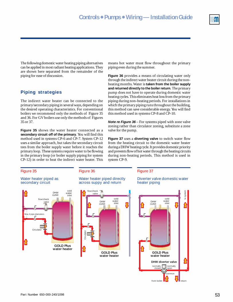
Part Number 650-000-240/1098 53
Controls ● Pumps ● Wiring — Installation Guide
Figure 37
Diverter valve domestic waterheater piping
Figure 36
Water heater piped directlyacross suppy and return
Figure 35
Water heater piped assecondary circuit
The following domestic water heating piping alternativescan be applied in most radiant heating applications. Theyare shown here separated from the remainder of thepiping for ease of discussion.
Piping strategies
The indirect water heater can be connected to theprimary/secondary piping in several ways, depending onthe desired operating characteristics. For conventionalboilers we recommend only the methods of Figure 35and 36. For GV boilers use only the methods of Figures35 or 37.
Figure 35 shows the water heater connected as asecondary circuit off of the primary. You will find thismethod used in systems CP-6 and CP-7. System CP-12uses a similar approach, but takes the secondary circuittees from the boiler supply water before it reaches theprimary loop. These systems require water to be flowingin the primary loop (or boiler supply piping for systemCP-12) in order to heat the indirect water heater. This
GOLD Pluswater heater
DHWoutlet
coldwater
inlet
Max 4 pipe diameters
flow/checkvalve
Circulator
GOLD Pluswater heater
flow/checkvalve
DHWoutlet
coldwater
inlet
Cir
cula
tor
GOLD Pluswater heater
DHW diverter valve
common
from boiler return
to s
yste
m
normallyopen
normallyclosed
DHWoutlet
coldwater
inlet
means hot water must flow throughout the primarypiping even during the summer.
Figure 36 provides a means of circulating water onlythrough the indirect water heater circuit during the non-heating months. Water is taken from the boiler supplyand returned directly to the boiler return. The primarypump does not have to operate during domestic waterheating cycles. This eliminates heat loss from the primarypiping during non-heating periods. For installations inwhich the primary piping runs throughout the building,this method can save considerable energy. You will findthis method used in systems CP-8 and CP-10.
Note re Figure 36 – For systems piped with zone valvezoning rather than circulator zoning, substitute a zonevalve for the pump.
Figure 37 uses a diverting valve to switch water flowfrom the heating circuit to the domestic water heaterduring a DHW heating cycle. It provides domestic priorityand prevents flow of hot water through the heating circuitsduring non-heating periods. This method is used insystem CP-9.
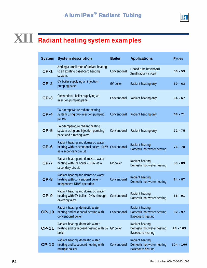
Part Number 650-000-240/109854
AlumiPAlumiPAlumiPAlumiPAlumiPeeeeexxxxx® ® ® ® ® Radiant TRadiant TRadiant TRadiant TRadiant Tubingubingubingubingubing
XII Radiant heating system examples
System System description Boiler Applications Pages
CP-1Adding a small zone of radiant heating to an existing baseboard heating system.
ConventionalFinned tube baseboardSmall radiant circuit
56 - 59
CP-2 GV boiler supplying an injection pumping panel
GV boiler Radiant heating only 60 - 63
CP-3 Conventional boiler supplying an injection pumping panel
Conventional Radiant heating only 64 - 67
CP-4Two-temperature radiant heating system using two injection pumping panels
Conventional Radiant heating only 68 - 71
CP-5Two-temperature radiant heating system using one injection pumping panel and a mixing valve
Conventional Radiant heating only 72 - 75
CP-6Radiant heating and domestic water heating with conventional boiler - DHW as a secondary circuit
ConventionalRadiant heatingDomestic hot water heating
76 - 78
CP-7Radiant heating and domestic water heating with GV boiler - DHW as a secondary circuit
GV boilerRadiant heatingDomestic hot water heating
80 - 83
CP-8Radiant heating and domestic water heating with conventional boiler - independent DHW operation
ConventionalRadiant heatingDomestic hot water heating
84 - 87
CP-9Radiant heating and domestic water heating with GV boiler - DHW through diverting valve
ConventionalRadiant heatingDomestic hot water heating
88 - 91
CP-10Radiant heating, domestic water heating and baseboard heating with conventional boiler
ConventionalRadiant heatingDomestic hot water heatingBaseboard heating
92 - 97
CP-11Radiant heating, domestic water heating and baseboard heating with GV boiler
GV boilerRadiant heatingDomestic hot water heatingBaseboard heating
98 - 103
CP-12Radiant heating, domestic water heating and baseboard heating with multiple boilers
ConventionalRadiant heatingDomestic hot water heatingBaseboard heating
104 - 109
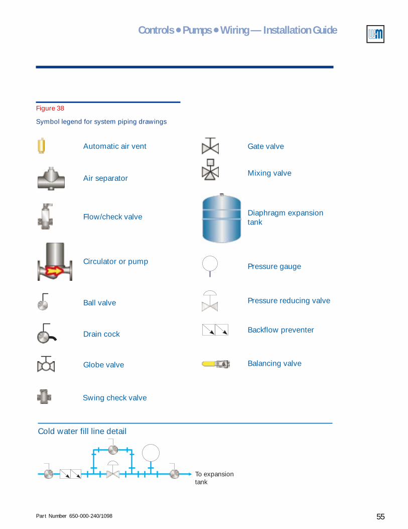
Part Number 650-000-240/1098 55
Controls ● Pumps ● Wiring — Installation Guide
Figure 38
Symbol legend for system piping drawings
To expansiontank
Cold water fill line detail
Automatic air vent
Air separator
Flow/check valve
Circulator or pump
Ball valve
Drain cock
Globe valve
Gate valve
Mixing valve
Diaphragm expansiontank
Pressure gauge
Pressure reducing valve
Backflow preventer
Balancing valve
Swing check valve
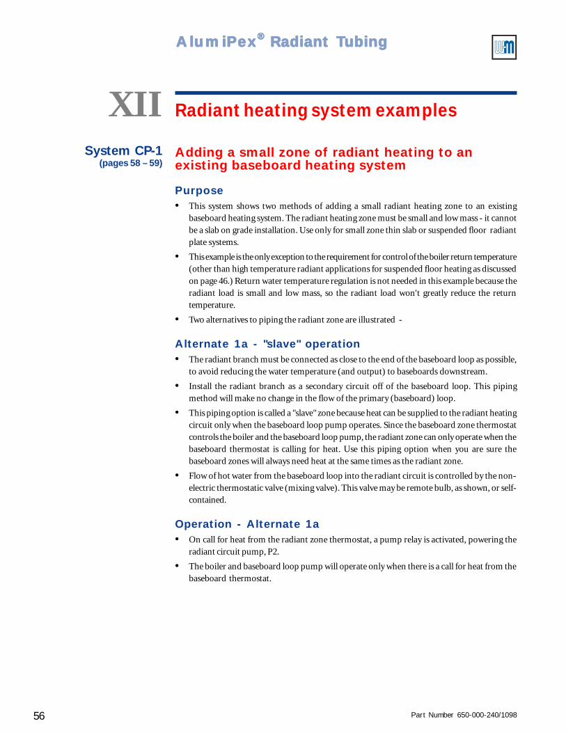
Part Number 650-000-240/109856
AlumiPAlumiPAlumiPAlumiPAlumiPeeeeexxxxx® ® ® ® ® Radiant TRadiant TRadiant TRadiant TRadiant Tubingubingubingubingubing
Radiant heating system examplesXIISystem CP-1
(pages 58 – 59)Adding a small zone of radiant heating to anexisting baseboard heating system
Purpose• This system shows two methods of adding a small radiant heating zone to an existing
baseboard heating system. The radiant heating zone must be small and low mass - it cannotbe a slab on grade installation. Use only for small zone thin slab or suspended floor radiantplate systems.
• This example is the only exception to the requirement for control of the boiler return temperature(other than high temperature radiant applications for suspended floor heating as discussedon page 46.) Return water temperature regulation is not needed in this example because theradiant load is small and low mass, so the radiant load won't greatly reduce the returntemperature.
• Two alternatives to piping the radiant zone are illustrated -
Alternate 1a - "slave" operation• The radiant branch must be connected as close to the end of the baseboard loop as possible,
to avoid reducing the water temperature (and output) to baseboards downstream.
• Install the radiant branch as a secondary circuit off of the baseboard loop. This pipingmethod will make no change in the flow of the primary (baseboard) loop.
• This piping option is called a "slave" zone because heat can be supplied to the radiant heatingcircuit only when the baseboard loop pump operates. Since the baseboard zone thermostatcontrols the boiler and the baseboard loop pump, the radiant zone can only operate when thebaseboard thermostat is calling for heat. Use this piping option when you are sure thebaseboard zones will always need heat at the same times as the radiant zone.
• Flow of hot water from the baseboard loop into the radiant circuit is controlled by the non-electric thermostatic valve (mixing valve). This valve may be remote bulb, as shown, or self-contained.
Operation - Alternate 1a• On call for heat from the radiant zone thermostat, a pump relay is activated, powering the
radiant circuit pump, P2.
• The boiler and baseboard loop pump will operate only when there is a call for heat from thebaseboard thermostat.
Part Number 650-000-240/1098 57
Controls ● Pumps ● Wiring — Installation Guide
Alternate 1b - "independent" operation• This option takes the radiant heating water directly across the boiler supply and return,
allowing it to operate independently of the baseboard circuit pump. You must install a flow/check valve in the baseboard circuit if not already installed when using this option, to preventshort circuiting the flow of the radiant pump.
• Use this alternative when you want the radiant zone to be capable of operation even whenthere is no demand from the baseboard zones. Do not use alternate 1b with a GV boiler - flowthrough the boiler can only be controlled by the integral pump.
• The non-electric thermostatic valve (mixing valve) regulates flow of hot water from thebaseboard circuit into the radiant circuit. This valve may be remote bulb, as shown, or self-contained.
Operation - Alternate 1b• The baseboard pump operates on call for heat from the baseboard thermostat, powered
through the pump relay. This relay also provides the call for heat signal to the boiler.
• A second relay is operated by the radiant zone thermostat. On call for heat from this thermostat,the radiant circuit pumps are activated – pump P2 (boiler pump that circulates water throughthe crossover bridge from boiler supply to return) and pump P3 (pump that circulates waterthrough the radiant tubing).
System CP-1
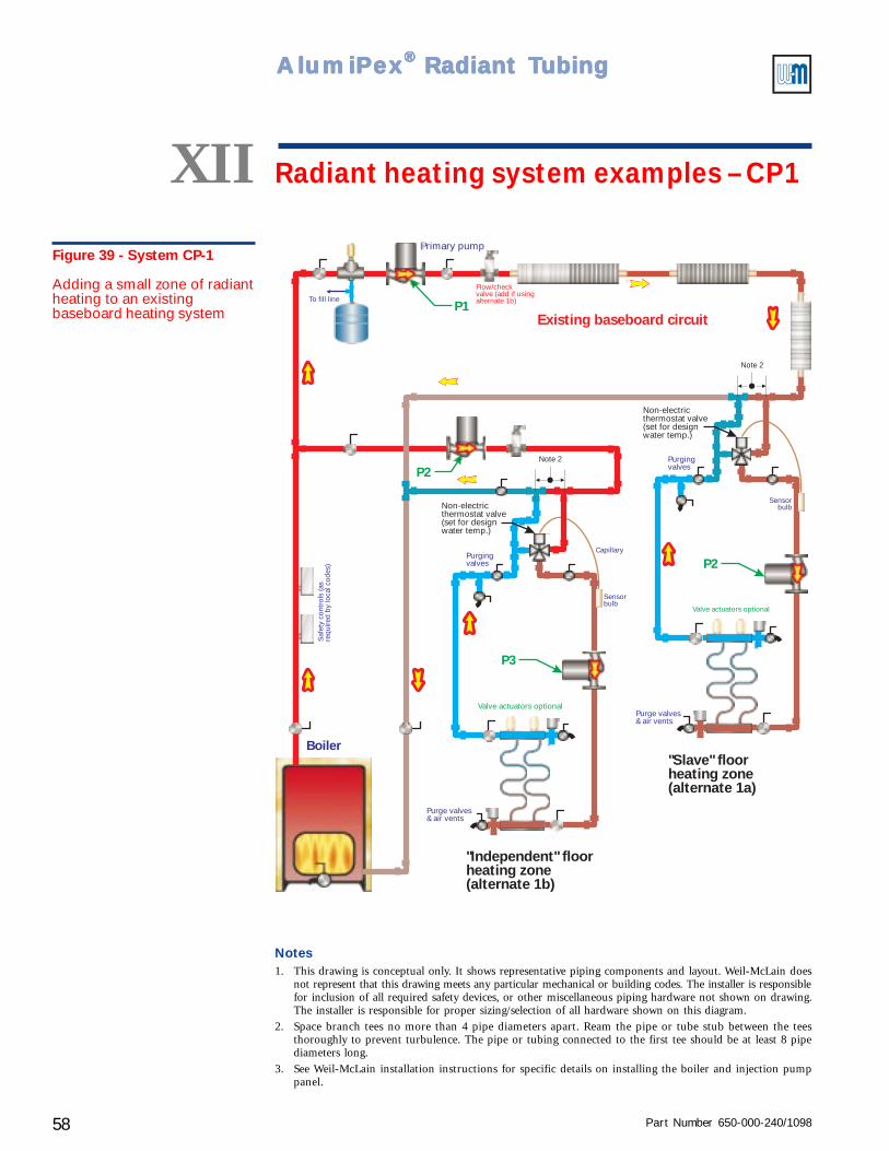
Part Number 650-000-240/109858
AlumiPAlumiPAlumiPAlumiPAlumiPeeeeexxxxx® ® ® ® ® Radiant TRadiant TRadiant TRadiant TRadiant Tubingubingubingubingubing
Figure 39 - System CP-1
Adding a small zone of radiantheating to an existingbaseboard heating system
XII Radiant heating system examples – CP1
To fill line
Boiler
P1
P2
P2
P3
Existing baseboard circuit
"Slave" floorheating zone(alternate 1a)
"Independent" floorheating zone(alternate 1b)
Saf
ety
cont
rols
(as
requ
ired
by lo
cal c
odes
)
Primary pump
Purge valves& air vents
Purge valves& air vents
Valve actuators optional
Valve actuators optional
Non-electricthermostat valve(set for designwater temp.)
Non-electricthermostat valve(set for designwater temp.)
Capillary
Flow/checkvalve (add if usingalternate 1b)
Sensorbulb
Sensorbulb
Note 2
Note 2
Purgingvalves
Purgingvalves
Notes1. This drawing is conceptual only. It shows representative piping components and layout. Weil-McLain does
not represent that this drawing meets any particular mechanical or building codes. The installer is responsiblefor inclusion of all required safety devices, or other miscellaneous piping hardware not shown on drawing.The installer is responsible for proper sizing/selection of all hardware shown on this diagram.
2. Space branch tees no more than 4 pipe diameters apart. Ream the pipe or tube stub between the teesthoroughly to prevent turbulence. The pipe or tubing connected to the first tee should be at least 8 pipediameters long.
3. See Weil-McLain installation instructions for specific details on installing the boiler and injection pumppanel.
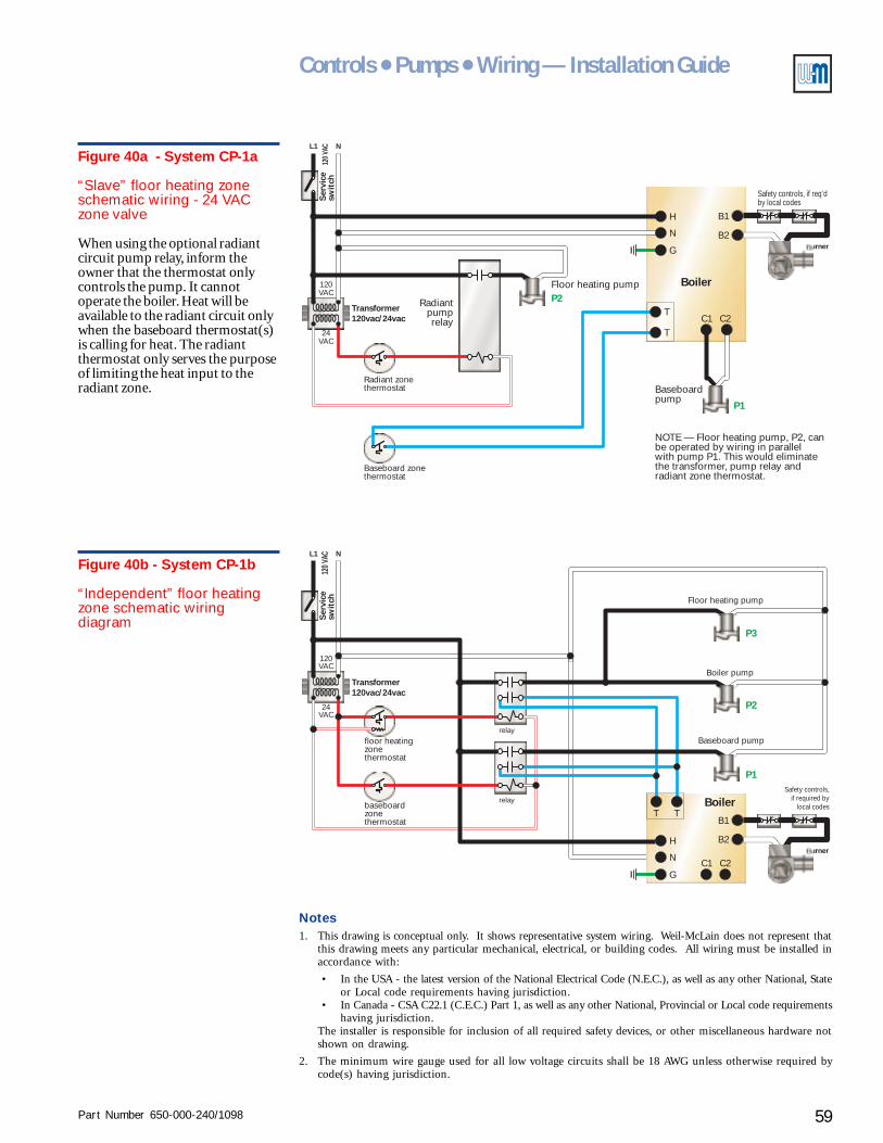
Part Number 650-000-240/1098 59
Controls ● Pumps ● Wiring — Installation Guide
L1 N
C1
B2
T
TC2
B1H
N
G
120VAC
24VAC
120 V
ACS
ervi
cesw
itch
Burner
Radiant zonethermostat
Baseboard zonethermostat
Floor heating pump
Baseboardpump
Boiler
Radiantpumprelay
NOTE — Floor heating pump, P2, canbe operated by wiring in parallelwith pump P1. This would eliminatethe transformer, pump relay andradiant zone thermostat.
Safety controls, if req’dby local codes
Transformer120vac/24vac
P2
P1
Figure 40a - System CP-1a
“Slave” floor heating zoneschematic wiring - 24 VACzone valve
When using the optional radiantcircuit pump relay, inform theowner that the thermostat onlycontrols the pump. It cannotoperate the boiler. Heat will beavailable to the radiant circuit onlywhen the baseboard thermostat(s)is calling for heat. The radiantthermostat only serves the purposeof limiting the heat input to theradiant zone.
Notes1. This drawing is conceptual only. It shows representative system wiring. Weil-McLain does not represent that
this drawing meets any particular mechanical, electrical, or building codes. All wiring must be installed inaccordance with:
• In the USA - the latest version of the National Electrical Code (N.E.C.), as well as any other National, Stateor Local code requirements having jurisdiction.
• In Canada - CSA C22.1 (C.E.C.) Part 1, as well as any other National, Provincial or Local code requirementshaving jurisdiction.
The installer is responsible for inclusion of all required safety devices, or other miscellaneous hardware notshown on drawing.
2. The minimum wire gauge used for all low voltage circuits shall be 18 AWG unless otherwise required bycode(s) having jurisdiction.
Figure 40b - System CP-1b
“Independent” floor heatingzone schematic wiringdiagram
L1 N
C1
B2
TT
C2
B1
H
N
G
120VAC
24VAC
120 V
ACS
ervi
cesw
itch
Burner
baseboardzonethermostat
floor heatingzonethermostat
Floor heating pump
Baseboard pump
Boiler pump
BoilerSafety controls,
if required bylocal codes
Transformer120vac/24vac
P1
P2
P3
relay
relay
Part Number 650-000-240/109860
AlumiPAlumiPAlumiPAlumiPAlumiPeeeeexxxxx® ® ® ® ® Radiant TRadiant TRadiant TRadiant TRadiant Tubingubingubingubingubing
Radiant heating system examplesXIIGV boiler supplying an injection pump panelSystem CP-2
(pages 62 – 63)
Purpose• Provide heating water to radiant circuits, using a control and injection pump that regulate
radiant circuit supply temperature and maintain minimum boiler return temperature.
Pumps and piping
Primary circuit
• The GV integral pump provides primary circuit flow.
Radiant circuits
• The Injection Pump Panel (IPP) includes the injection pump and radiant circuit pump. (Forapplications larger than the capacity of the IPP, use multiple IPP panels or use an IPC InjectionPump Control with an injection pump and radiant circuit pump sized for the flow rates andpressure drops needed.)
Radiant heating circuits• System CP-1 shows two manifold locations. The same piping design can be used for multiple
manifolds.
• Manifold valve actuators are optional, but recommended as discussed in Zoning radiantheating systems, section IV of this Guide. When actuators are not used, provide the call forheat signal to the IPC (24 volt or 120 volt signal to terminals 15 and 16) through a zonethermostat or a dry contact that closes on a call for heat. Alternatively, use an indoor sensoror zone control.
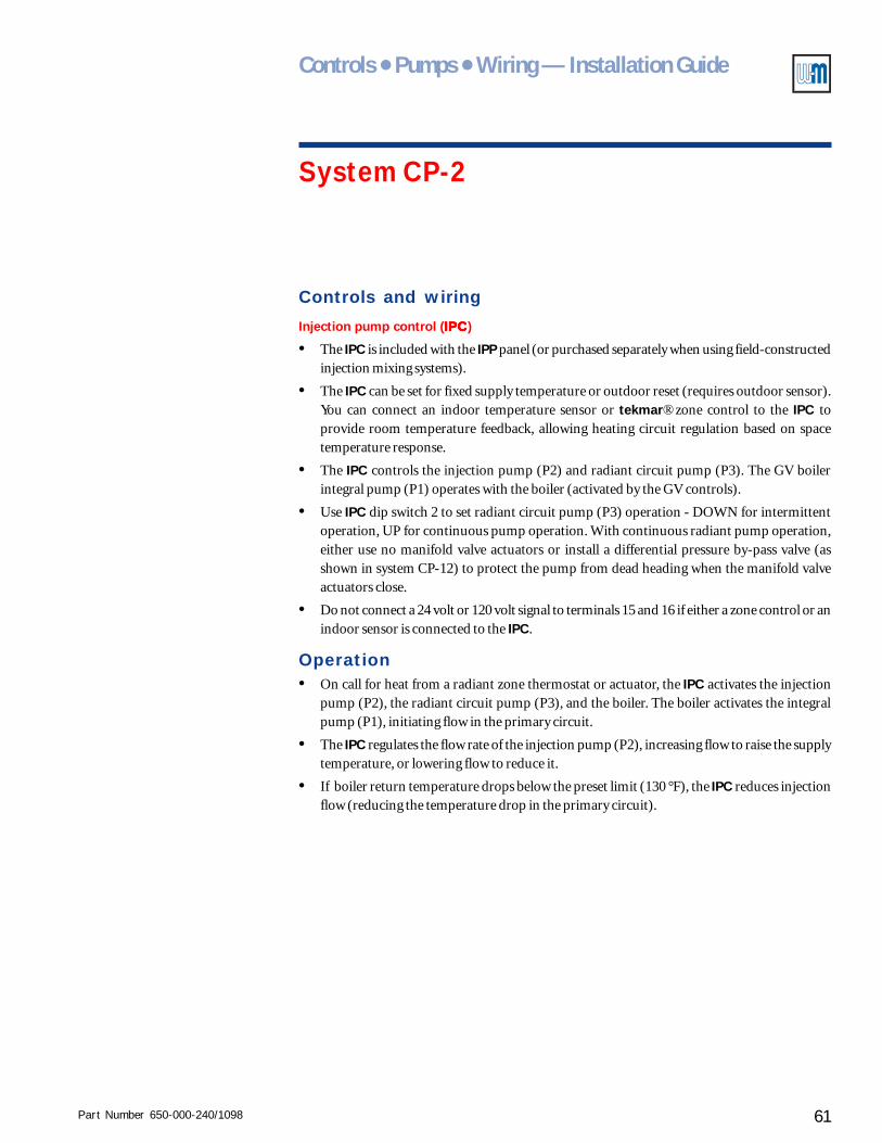
Part Number 650-000-240/1098 61
Controls ● Pumps ● Wiring — Installation Guide
System CP-2
Controls and wiring
Injection pump control (IPCIPCIPCIPCIPC)
• The IPC is included with the IPP panel (or purchased separately when using field-constructedinjection mixing systems).
• The IPC can be set for fixed supply temperature or outdoor reset (requires outdoor sensor).You can connect an indoor temperature sensor or tekmar® zone control to the IPC toprovide room temperature feedback, allowing heating circuit regulation based on spacetemperature response.
• The IPC controls the injection pump (P2) and radiant circuit pump (P3). The GV boilerintegral pump (P1) operates with the boiler (activated by the GV controls).
• Use IPC dip switch 2 to set radiant circuit pump (P3) operation - DOWN for intermittentoperation, UP for continuous pump operation. With continuous radiant pump operation,either use no manifold valve actuators or install a differential pressure by-pass valve (asshown in system CP-12) to protect the pump from dead heading when the manifold valveactuators close.
• Do not connect a 24 volt or 120 volt signal to terminals 15 and 16 if either a zone control or anindoor sensor is connected to the IPC.
Operation• On call for heat from a radiant zone thermostat or actuator, the IPC activates the injection
pump (P2), the radiant circuit pump (P3), and the boiler. The boiler activates the integralpump (P1), initiating flow in the primary circuit.
• The IPC regulates the flow rate of the injection pump (P2), increasing flow to raise the supplytemperature, or lowering flow to reduce it.
• If boiler return temperature drops below the preset limit (130 °F), the IPC reduces injectionflow (reducing the temperature drop in the primary circuit).
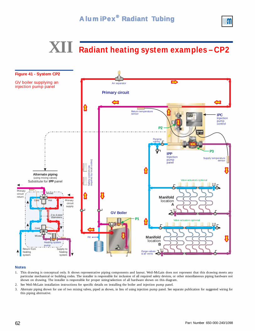
Part Number 650-000-240/109862
AlumiPAlumiPAlumiPAlumiPAlumiPeeeeexxxxx® ® ® ® ® Radiant TRadiant TRadiant TRadiant TRadiant Tubingubingubingubingubing
Fill
GV Boiler
P1
P3
P2
Manifold
Alocation
Manifold
Blocation
Primary circuitS
afet
y co
ntro
ls (a
sre
quir
ed b
y lo
cal c
odes
)
Return temperaturesensor
Purge valves& air vents
Supply temperaturesensor
Air separator
Valve actuators optional
Valve actuators optional
Purgingvalves
Alternate piping
IPPSubstitute for panel(using mixing valves)
Heating systempump
Return fromheatingsystem
Supply toheatingsystem
Primarycircuitsupply
Primarycircuitreturn
Hot
Hot
Mixed
Mixed
Cold
2 to 4 pipediameters
Cold
IPCInjectionpumpcontrol
IPPInjectionpumppanel
Figure 41 - System CP2
GV boiler supplying aninjection pump panel
Notes1. This drawing is conceptual only. It shows representative piping components and layout. Weil-McLain does not represent that this drawing meets any
particular mechanical or building codes. The installer is responsible for inclusion of all required safety devices, or other miscellaneous piping hardware notshown on drawing. The installer is responsible for proper sizing/selection of all hardware shown on this diagram.
2. See Weil-McLain installation instructions for specific details on installing the boiler and injection pump panel.
3. Alternate piping shown for use of two mixing valves, piped as shown, in lieu of using injection pump panel. See separate publication for suggested wiring forthis piping alternative.
XII Radiant heating system examples – CP2
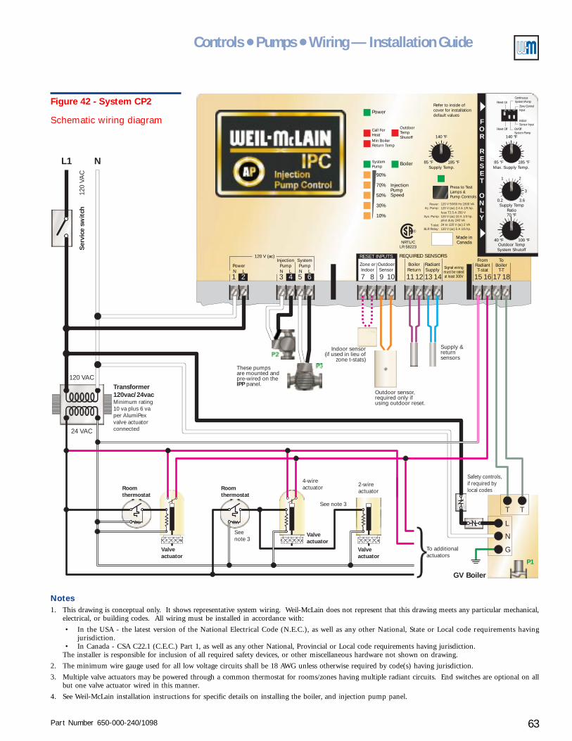
Part Number 650-000-240/1098 63
Controls ● Pumps ● Wiring — Installation Guide
LR 58223NRTL/C
OutdoorTempShutoff
Press to TestLamps &Pump Controls
Refer to inside ofcover for installationdefault values
BoilerSupply Temp. Max. Supply Temp.
Supply TempRatio
Outdoor TempSystem Shutoff
185 °F 185 °F
100 °F
85 °F 85 °F
40 °F
0.2 3.6
3
21
140 °F 140 °F
70 °F
InjectionPumpSpeed
10
30
90
70
50
SystemPump
Min BoilerReturn Temp
Call ForHeat
%
%
%
%
%
Power
REQUIRED SENSORSRESET INPUTS
Zone orIndoor
InjectionPumpN L
SystemPumpN L
PowerN L
120 V (ac)
BoilerReturn
FromRadiantT-stat
ToBoiler
T-T
Made inCanada
RadiantSupply
OutdoorSensor Signal wiring
must be ratedat least 300V
Power: 120 V 50/60 Hz 1500 VA120 V (ac) 2.4 A 1/5 hp.
120 V (ac) 5 A 1/6 hp.
120 V (ac) 10 A 1/3 hp.
24 to 120 V (ac) 2 VA
fuse T2.5 A 250 V
pilot duty 240 VA
Inj. Pump:
Sys. Pump
T-stat:BLR Relay:
®
3 7 11 151 8 12 162 5 9 13 176 10 14 184
FOR
RESET
ONLY
1 2 3
Reset Off
Reset On
On/OffSystem Pump
IndoorSensor Input
Zone ControlInput
ContinuousSystem Pump
L1 N
T T
L
N
G
P1
120 VAC
120
VAC
Ser
vice
sw
itch
Transformer120vac/24vacMinimum rating10 va plus 6 vaper AlumiPexvalve actuatorconnected
Roomthermostat
Roomthermostat
P2
P3
Valveactuator
Valveactuator
See note 3
Seenote 3
These pumpsare mounted andpre-wired on the
panel.IPPOutdoor sensor,required only ifusing outdoor reset.
Supply &returnsensors
To additionalactuators
Safety controls,if required bylocal codes
GV Boiler
Valveactuator
24 VAC
2-wireactuator
4-wireactuator
Indoor sensor(if used in lieu of
zone t-stats)
Notes1. This drawing is conceptual only. It shows representative system wiring. Weil-McLain does not represent that this drawing meets any particular mechanical,
electrical, or building codes. All wiring must be installed in accordance with:
• In the USA - the latest version of the National Electrical Code (N.E.C.), as well as any other National, State or Local code requirements havingjurisdiction.
• In Canada - CSA C22.1 (C.E.C.) Part 1, as well as any other National, Provincial or Local code requirements having jurisdiction.The installer is responsible for inclusion of all required safety devices, or other miscellaneous hardware not shown on drawing.
2. The minimum wire gauge used for all low voltage circuits shall be 18 AWG unless otherwise required by code(s) having jurisdiction.
3. Multiple valve actuators may be powered through a common thermostat for rooms/zones having multiple radiant circuits. End switches are optional on allbut one valve actuator wired in this manner.
4. See Weil-McLain installation instructions for specific details on installing the boiler, and injection pump panel.
Figure 42 - System CP2
Schematic wiring diagram
Part Number 650-000-240/109864
AlumiPAlumiPAlumiPAlumiPAlumiPeeeeexxxxx® ® ® ® ® Radiant TRadiant TRadiant TRadiant TRadiant Tubingubingubingubingubing
Radiant heating system examplesXIISystem CP-3
(pages 66 – 67)Conventional boiler supplying an injection pumppanel
Purpose• Provide heating water to radiant circuits, using a control and injection pump that regulate
radiant circuit supply temperature and maintain minimum boiler return temperature.
Pumps and piping
Primary circuit
• The primary pump can be as supplied with the boiler or purchased separately.
• Residential packaged boilers may have the pump mounted on the return piping at the boiler.The pump can be used in this location provided the expansion tank or compression tank andfill line are correctly located.
Radiant circuits
• The Injection Pump Panel (IPP) includes the injection pump and the radiant circuit pump.(For applications larger than the capacity of the IPP, use multiple IPP panels or use an IPCInjection Pump Control with an injection pump and radiant circuit pump sized for the flowrates and pressure drops needed.)
Radiant heating circuits• System CP-2 shows two manifold locations. The same piping design can be used for multiple
manifolds.
• Manifold valve actuators are optional, but recommended as discussed in Zoning radiantheating systems, section IV of this Guide. When actuators are not used, provide the call forheat signal to the IPC (24 volt or 120 volt signal to terminals 15 and 16) through a zonethermostat or a dry contact that closes on a call for heat. Alternatively, use an indoor sensoror zone control.
Part Number 650-000-240/1098 65
Controls ● Pumps ● Wiring — Installation Guide
System CP-3
Controls and wiring
Injection pump control (IPCIPCIPCIPCIPC)
• The IPC (Injection Pump Control) is included with the IPP panel (or purchased separatelywhen using field-constructed injection mixing systems).
• The IPC can be set for fixed supply temperature or outdoor reset (requires outdoor sensor).You can connect an indoor temperature sensor or tekmar® zone control to the IPC toprovide room temperature feedback to the control, allowing heating circuit regulation basedon space temperature response.
• The IPC controls the injection pump (P2) and radiant circuit pump (P3). The primary pump(P1) operates with the boiler (activated by the boiler controls).
• Use IPC dip switch 2 to set radiant circuit pump (P3) operation - DOWN for intermittentoperation, UP for continuous pump operation. With continuous radiant pump operation,either use no manifold valve actuators or install a differential pressure by-pass valve (asshown in system CP-12) to protect the pump from dead heading when the manifold valveactuators close.
• Do not connect a 24 volt or 120 volt signal to terminals 15 and 16 if either a zone control or anindoor sensor is connected to the IPC.
Operation• On call for heat from a radiant zone thermostat or actuator, the IPC activates the injection
pump (P2), the radiant circuit pump (P3), and the boiler. The boiler activates the primarypump (P1), initiating primary circuit flow.
• The IPC regulates the flow rate of the injection pump (P2), increasing flow to raise the supplytemperature, or lowering flow to reduce it.
• If boiler return temperature drops below the preset limit (130 °F), the IPC reduces injectionflow (reducing the temperature drop in the primary circuit).
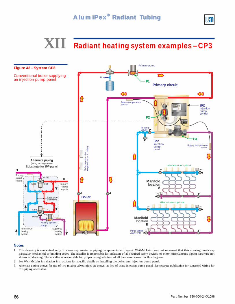
Part Number 650-000-240/109866
AlumiPAlumiPAlumiPAlumiPAlumiPeeeeexxxxx® ® ® ® ® Radiant TRadiant TRadiant TRadiant TRadiant Tubingubingubingubingubing
Fill
Boiler
P1
P2
Primary circuit
Primary pump
P3
Manifold
Alocation
Manifold
Blocation
Saf
ety
cont
rols
(as
requ
ired
by
loca
l cod
es)
Return temperaturesensor
Purge valves& air vents
Supply temperaturesensor
Valve actuators optional
Valve actuators optional
Purgingvalves
Alternate piping
IPPSubstitute for panel(using mixing valves)
Heating systempump
Return fromheatingsystem
Supply toheatingsystem
Primarycircuitsupply
Primarycircuitreturn
Hot
Hot
Mixed
Mixed
Cold
2 to 4 pipediameters
Cold
IPCInjectionpumpcontrol
IPPInjectionpumppanel
Figure 43 - System CP3
Conventional boiler supplyingan injection pump panel
XII Radiant heating system examples – CP3
Notes1. This drawing is conceptual only. It shows representative piping components and layout. Weil-McLain does not represent that this drawing meets any
particular mechanical or building codes. The installer is responsible for inclusion of all required safety devices, or other miscellaneous piping hardware notshown on drawing. The installer is responsible for proper sizing/selection of all hardware shown on this diagram.
2. See Weil-McLain installation instructions for specific details on installing the boiler and injection pump panel.
3. Alternate piping shown for use of two mixing valves, piped as shown, in lieu of using injection pump panel. See separate publication for suggested wiring forthis piping alternative.
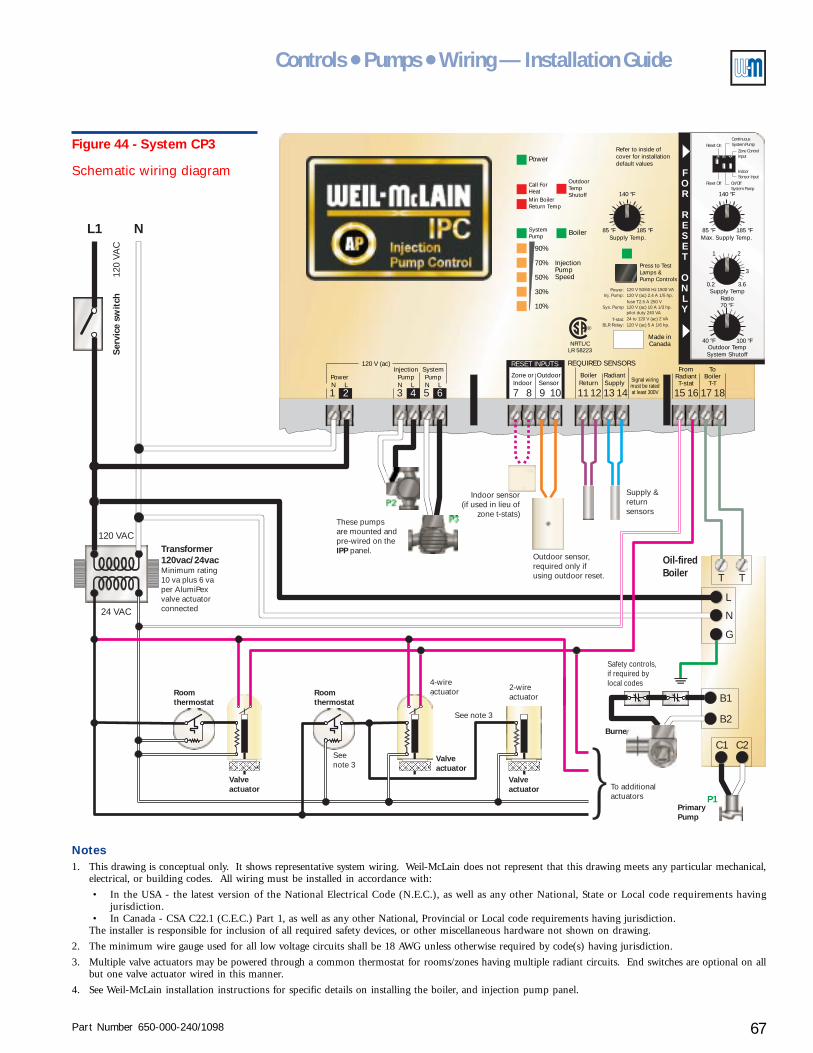
Part Number 650-000-240/1098 67
Controls ● Pumps ● Wiring — Installation Guide
2-wireactuator
4-wireactuator
LR 58223NRTL/C
OutdoorTempShutoff
Press to TestLamps &Pump Controls
Refer to inside ofcover for installationdefault values
BoilerSupply Temp. Max. Supply Temp.
Supply TempRatio
Outdoor TempSystem Shutoff
185 °F 185 °F
100 °F
85 °F 85 °F
40 °F
0.2 3.6
3
21
140 °F 140 °F
70 °F
InjectionPumpSpeed
10
30
90
70
50
SystemPump
Min BoilerReturn Temp
Call ForHeat
%
%
%
%
%
Power
REQUIRED SENSORSRESET INPUTS
Zone orIndoor
InjectionPumpN L
SystemPumpN L
PowerN L
120 V (ac)
BoilerReturn
FromRadiantT-stat
ToBoiler
T-T
Made inCanada
RadiantSupply
OutdoorSensor Signal wiring
must be ratedat least 300V
Power: 120 V 50/60 Hz 1500 VA120 V (ac) 2.4 A 1/5 hp.
120 V (ac) 5 A 1/6 hp.
120 V (ac) 10 A 1/3 hp.
24 to 120 V (ac) 2 VA
fuse T2.5 A 250 V
pilot duty 240 VA
Inj. Pump:
Sys. Pump
T-stat:BLR Relay:
®
3 7 11 151 8 12 162 5 9 13 176 10 14 184
FOR
RESET
ONLY
1 2 3
Reset Off
Reset On
On/OffSystem Pump
IndoorSensor Input
Zone ControlInput
ContinuousSystem Pump
L1 N
T
C1
B2
T
C2
B1
L
N
G
P1
120 VAC
120
VAC
Ser
vice
sw
itch
Roomthermostat
Roomthermostat
P2
P3
Valveactuator
Valveactuator
See note 3
Seenote 3
These pumpsare mounted andpre-wired on the
panel.IPPOutdoor sensor,required only ifusing outdoor reset.
Supply &returnsensors
To additionalactuators
PrimaryPump
Burner
Safety controls,if required bylocal codes
Oil-firedBoiler
Indoor sensor(if used in lieu of
zone t-stats)
Valveactuator
24 VAC
Transformer120vac/24vacMinimum rating10 va plus 6 vaper AlumiPexvalve actuatorconnected
Figure 44 - System CP3
Schematic wiring diagram
Notes1. This drawing is conceptual only. It shows representative system wiring. Weil-McLain does not represent that this drawing meets any particular mechanical,
electrical, or building codes. All wiring must be installed in accordance with:
• In the USA - the latest version of the National Electrical Code (N.E.C.), as well as any other National, State or Local code requirements havingjurisdiction.
• In Canada - CSA C22.1 (C.E.C.) Part 1, as well as any other National, Provincial or Local code requirements having jurisdiction.The installer is responsible for inclusion of all required safety devices, or other miscellaneous hardware not shown on drawing.
2. The minimum wire gauge used for all low voltage circuits shall be 18 AWG unless otherwise required by code(s) having jurisdiction.
3. Multiple valve actuators may be powered through a common thermostat for rooms/zones having multiple radiant circuits. End switches are optional on allbut one valve actuator wired in this manner.
4. See Weil-McLain installation instructions for specific details on installing the boiler, and injection pump panel.
Part Number 650-000-240/109868
AlumiPAlumiPAlumiPAlumiPAlumiPeeeeexxxxx® ® ® ® ® Radiant TRadiant TRadiant TRadiant TRadiant Tubingubingubingubingubing
Radiant heating system examplesXIISystem CP-4
(pages 70 – 71)Two-temperature radiant heating system usingtwo injection pump panels
Purpose• Provide heating water to two radiant circuits - each requiring a different temperature. The
controls and injection pumps regulate radiant circuit supply temperature and maintainminimum boiler return temperature.
Pumps and piping
Primary circuit
• The primary pump can be as supplied with the boiler or purchased separately.
• Residential packaged boilers may have the pump mounted on the return piping at the boiler.The pump can be used in this location provided the expansion tank or compression tank andfill line are correctly located.
Radiant circuits
• The Injection Pump Panel (IPP) includes the injection pump and the radiant circuit pump.(For applications larger than the capacity of the IPP, use multiple IPP panels or use an IPCInjection Pump Control with an injection pump and radiant circuit pump sized for the flowrates and pressure drops needed.)
Radiant heating circuits• Install the injection pump panel for the higher temperature subsystem upstream of the lower
temperature circuit injection pump panel to assure hotter supply water. This is illustrated insystem CP-4, where Circuit #1 is the higher temperature circuit.
• System CP-4 shows two manifold locations for Circuit #2 and one for Circuit #1. The samepiping design can be used for multiple manifolds.
• Manifold valve actuators are optional, but recommended as discussed in Zoning radiantheating systems, section IV of this Guide. When actuators are not used, provide the call forheat signal to the IPC (24 volt or 120 volt signal to terminals 15 and 16) through a zonethermostat or a dry contact that closes on a call for heat. Alternatively, use an indoor sensoror zone control.
Part Number 650-000-240/1098 69
Controls ● Pumps ● Wiring — Installation Guide
System CP-4
Controls and wiring
Injection pump control (IPCIPCIPCIPCIPC)
• An IPC is included with each IPP panel (or purchased separately when using field-constructedinjection mixing systems).
• The IPC can be set for fixed supply temperature or outdoor reset (requires outdoor sensor).You can connect an indoor temperature sensor or tekmar® zone control to the IPC toprovide room temperature feedback to the control, allowing heating circuit regulation basedon space temperature response.
• The IPC's control the injection pumps (P2 and P4) and radiant circuit pumps (P3 and P5).The primary pump (P1) operates with the boiler (activated by the boiler controls).
• On each IPC, use dip switch 2 to set radiant pump operation - DOWN for intermittentoperation, UP for continuous pump operation. With continuous radiant pump operation,either use no manifold valve actuators or install a differential pressure by-pass valve (asshown in system CP-12) to protect the pump from dead heading when the manifold valveactuators close.
• Do not connect a 24 volt or 120 volt signal to terminals 15 and 16 if either a zone control or anindoor sensor is connected to the IPC.
Operation
• On call for heat from a radiant zone thermostat or actuator, the corresponding IPC activatesits injection pump, radiant circuit pump and the boiler. The boiler activates the primarypump (P1), initiating primary circuit flow.
• The IPC's regulate the injection pump flow rates, increasing flow to raise the supply temperature,or lowering flow to reduce it.
• If boiler return temperature drops below the preset limit (130 °F), the IPC reduces injectionflow (reducing the temperature drop in the primary circuit).
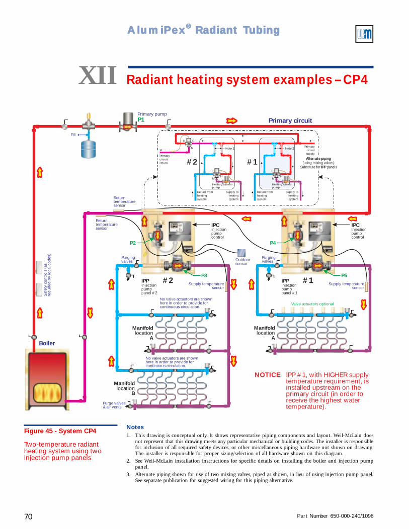
Part Number 650-000-240/109870
AlumiPAlumiPAlumiPAlumiPAlumiPeeeeexxxxx® ® ® ® ® Radiant TRadiant TRadiant TRadiant TRadiant Tubingubingubingubingubing
Fill
Boiler
P1
P3 P5
P2 P4
IPPInjectionpumppanel #2
IPPInjectionpumppanel #1
IPCInjectionpumpcontrol
IPCInjectionpumpcontrol
Manifold
Alocation
Manifold
Alocation
Manifold
Blocation
Primary circuit
#1#2
#2 #1
IPP #1, with HIGHER supplytemperature requirement, isinstalled upstream on theprimary circuit (in order toreceive the highest watertemperature).
NOTICE
Saf
ety
cont
rols
(as
requ
ired
by
loca
l cod
es)
Returntemperaturesensor
Outdoorsensor
Returntemperaturesensor
Primary pump
Supply temperaturesensor
Supply temperaturesensor
Valve actuators optionalNo valve actuators are shownhere in order to provide forcontinuous circulation.
No valve actuators are shownhere in order to provide forcontinuous circulation.
Purge valves& air vents
Purgingvalves
Purgingvalves
Heating systempump
Heating systempump
Return fromheatingsystem
Return fromheatingsystem
Supply toheatingsystem
Supply toheatingsystem
Primarycircuitsupply
Primarycircuitreturn
H HM M
M
C C
CH
Note 2Note 2
Alternate piping
IPP(using mixing valves)
Substitute for panels
Figure 45 - System CP4
Two-temperature radiantheating system using twoinjection pump panels
XII Radiant heating system examples – CP4
Notes1. This drawing is conceptual only. It shows representative piping components and layout. Weil-McLain does
not represent that this drawing meets any particular mechanical or building codes. The installer is responsiblefor inclusion of all required safety devices, or other miscellaneous piping hardware not shown on drawing.The installer is responsible for proper sizing/selection of all hardware shown on this diagram.
2. See Weil-McLain installation instructions for specific details on installing the boiler and injection pumppanel.
3. Alternate piping shown for use of two mixing valves, piped as shown, in lieu of using injection pump panel.See separate publication for suggested wiring for this piping alternative.
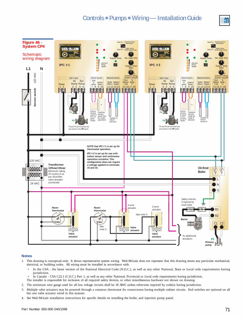
Part Number 650-000-240/1098 71
Controls ● Pumps ● Wiring — Installation Guide
L1 N
T
C1
B2
T
C2
B1
L
N
G
P1
120 VAC
120
VAC
Ser
vice
sw
itch
Roomthermostat
Roomthermostat
Valveactuator
Valveactuator
See note 3
Seenote 3
2-wireactuator
4-wireactuator
NOTE that IPC #1 is set up forthermostat operation.
IPC #2 is set up for use withindoor sensor and continuousoperation circulator. Thisconfiguration does not requirea voltage applied to terminals15 and 16.
To additionalactuators
Primarypump
Burner
Safety controls,if required bylocal codes
Oil-firedBoiler
Valveactuator
24 VAC
Transformer120vac/24vacMinimum rating10 va plus 6 vaper AlumiPexvalve actuatorconnected
Supply Temp.
Outdoor TempSystem Shutoff
InjectionPumpSpeed
InjPump
SysPumpPower
120 V (ac)
31 2 5 64
Required sensorsZone
orIndoor
BoilerReturn
RadiantSupply
OutdoorSensor
7 118 129 1310 14
FromRadiantT-stat
ToBoiler
T-T15 16 17 18
Max. Supply Temp.
Supply TempRatio
Reset Off
Reset On
On/Off System PumpIndoor Sensor
Zone ControlContinuous Pump
Reset inputs
P2
P3
P3 and P4 are mounted andpre-wired on the panel.IPP
Outdoorsensor,used onlyfor resetoperation
Supply &returnsensors
Supply Temp.
Outdoor TempSystem Shutoff
InjectionPumpSpeed
InjPump
SysPumpPower
120 V (ac)
31 2 5 64
Required sensorsZone
orIndoor
BoilerReturn
RadiantSupply
OutdoorSensor
7 118 129 1310 14
FromRadiantT-stat
ToBoiler
T-T15 16 17 18
Max. Supply Temp.
Supply TempRatio
Reset Off
Reset On
On/Off System PumpIndoor Sensor
Zone ControlContinuous Pump
Reset inputs
P4
P5
P3 and P4 are mounted andpre-wired on the panel.IPP
Outdoorsensor,used forreset ifdesired
Supply &returnsensors
Indoorsensor,if usedin lieuof zonet'stats
Indoorsensor,used inlieu ofzonet'stats
IPC #1 IPC #2
Figure 46 -System CP4
Schematicwiring diagram
Notes1. This drawing is conceptual only. It shows representative system wiring. Weil-McLain does not represent that this drawing meets any particular mechanical,
electrical, or building codes. All wiring must be installed in accordance with:
• In the USA - the latest version of the National Electrical Code (N.E.C.), as well as any other National, State or Local code requirements havingjurisdiction.
• In Canada - CSA C22.1 (C.E.C.) Part 1, as well as any other National, Provincial or Local code requirements having jurisdiction.The installer is responsible for inclusion of all required safety devices, or other miscellaneous hardware not shown on drawing.
2. The minimum wire gauge used for all low voltage circuits shall be 18 AWG unless otherwise required by code(s) having jurisdiction.
3. Multiple valve actuators may be powered through a common thermostat for rooms/zones having multiple radiant circuits. End switches are optional on allbut one valve actuator wired in this manner.
4. See Weil-McLain installation instructions for specific details on installing the boiler, and injection pump panel.
Part Number 650-000-240/109872
AlumiPAlumiPAlumiPAlumiPAlumiPeeeeexxxxx® ® ® ® ® Radiant TRadiant TRadiant TRadiant TRadiant Tubingubingubingubingubing
Radiant heating system examplesXIISystem CP-5
(pages 74 – 75)Two-temperature radiant heating system usingone injection pump panel and a mixing valve
Purpose• Provide heating water to two radiant circuits - each requiring a different water supply
temperature. The control and injection pump provide water hot enough for the highertemperature radiant circuit, and maintain a minimum boiler return temperature. A mixingvalve regulates the supply water to the lower temperature circuit.
Pumps and piping
Primary circuit
• The primary pump can be as supplied with the boiler or purchased separately.
• Residential packaged boilers may have the pump mounted on the return piping at the boiler.The pump can be used in this location provided the expansion tank or compression tank andfill line are correctly located.
Radiant circuits
• The Injection Pump Panel (IPP) includes the injection pump and the radiant circuit pump.(For applications larger than the capacity of the IPP, use multiple IPP panels or use an IPCInjection Pump Control with an injection pump and radiant circuit pump sized for the flowrates and pressure drops needed.)
• Pipe the radiant circuit requiring the higher water temperature (Circuit #2 in system CP-5)directly off of the radiant supply line as shown.
• Install a bridge for connection of the lower temperature radiant circuit (Circuit #1 in systemCP-5). Install a balancing valve in the bridge as shown. Throttle the valve enough to push therequired water through radiant Circuit #2.
• Provide a pump and a three-way mixing valve for the lower temperature circuit (Circuit #1 inCP-5). Assure that the pump is sized to handle the mixing valve pressure drop.
• System CP-5 shows one manifold location for each of the radiant circuits. The same pipingdesign can be used for multiple manifolds.
• Manifold valve actuators are optional, but recommended as discussed in Zoning radiantheating systems, section IV of this Guide. When actuators are not used, provide the call forheat signal to the IPC (24 volt or 120 volt signal to terminals 15 and 16) through a zonethermostat or a dry contact that closes on a call for heat. Alternatively, use an indoor sensoror zone control.
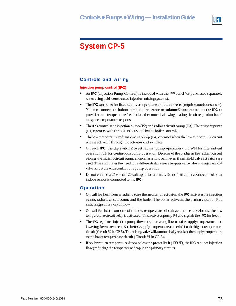
Part Number 650-000-240/1098 73
Controls ● Pumps ● Wiring — Installation Guide
System CP-5
Controls and wiring
Injection pump control (IPCIPCIPCIPCIPC)
• An IPC (Injection Pump Control) is included with the IPP panel (or purchased separatelywhen using field-constructed injection mixing systems).
• The IPC can be set for fixed supply temperature or outdoor reset (requires outdoor sensor).You can connect an indoor temperature sensor or tekmar® zone control to the IPC toprovide room temperature feedback to the control, allowing heating circuit regulation basedon space temperature response.
• The IPC controls the injection pump (P2) and radiant circuit pump (P3). The primary pump(P1) operates with the boiler (activated by the boiler controls).
• The low temperature radiant circuit pump (P4) operates when the low temperature circuitrelay is activated through the actuator end switches.
• On each IPC, use dip switch 2 to set radiant pump operation - DOWN for intermittentoperation, UP for continuous pump operation. Because of the bridge in the radiant circuitpiping, the radiant circuit pump always has a flow path, even if manifold valve actuators areused. This eliminates the need for a differential pressure by-pass valve when using manifoldvalve actuators with continuous pump operation.
• Do not connect a 24 volt or 120 volt signal to terminals 15 and 16 if either a zone control or anindoor sensor is connected to the IPC.
Operation• On call for heat from a radiant zone thermostat or actuator, the IPC activates its injection
pump, radiant circuit pump and the boiler. The boiler activates the primary pump (P1),initiating primary circuit flow.
• On call for heat from one of the low temperature circuit actuator end switches, the lowtemperature circuit relay is activated. This activates pump P4 and signals the IPC for heat.
• The IPC regulates injection pump flow rate, increasing flow to raise supply temperature - orlowering flow to reduce it. Set the IPC supply temperature as needed for the higher temperaturecircuit (Circuit #2 in CP-5). The mixing valve will automatically regulate the supply temperatureto the lower temperature circuit (Circuit #1 in CP-5).
• If boiler return temperature drops below the preset limit (130 °F), the IPC reduces injectionflow (reducing the temperature drop in the primary circuit).
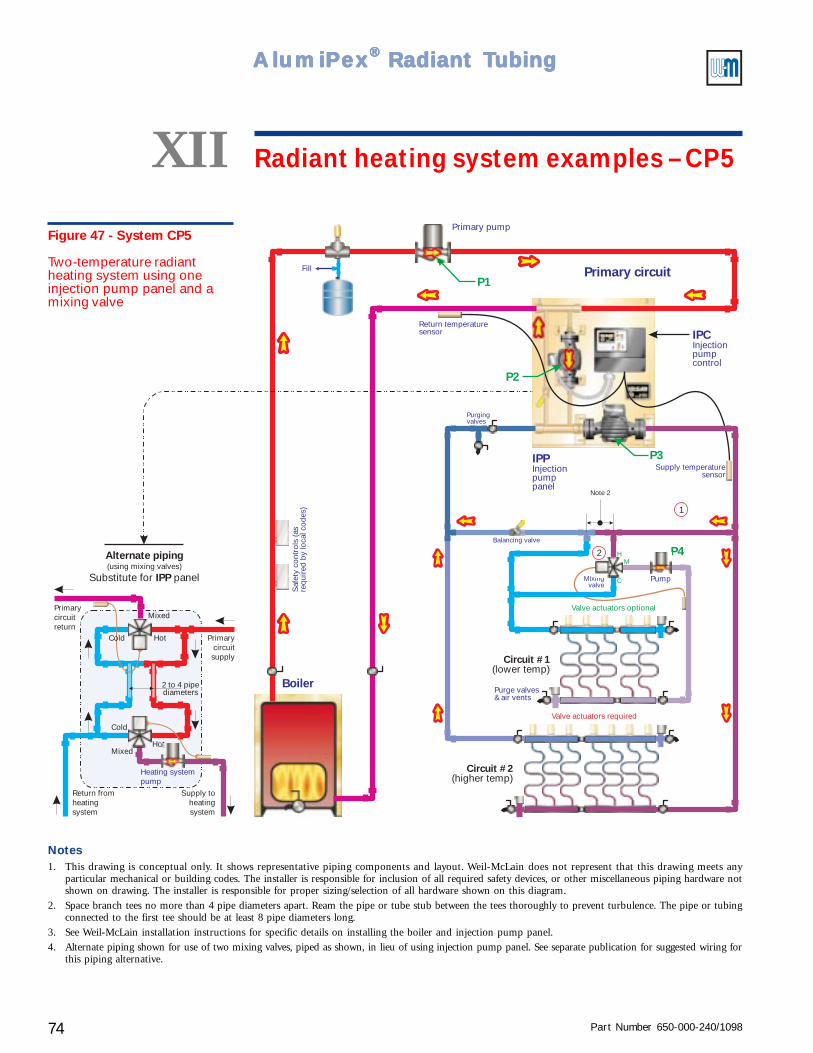
Part Number 650-000-240/109874
AlumiPAlumiPAlumiPAlumiPAlumiPeeeeexxxxx® ® ® ® ® Radiant TRadiant TRadiant TRadiant TRadiant Tubingubingubingubingubing
Fill
Boiler
P1
P2
P4
Primary circuit
Primary pump
Saf
ety
cont
rols
(as
requ
ired
by
loca
l cod
es)
Return temperaturesensor
P3
Circuit #1(lower temp)
Supply temperaturesensor
Note 2
Balancing valve
Mixingvalve
H
C
M
Pump
1
Valve actuators optional
Valve actuators required
Circuit #2(higher temp)
Purge valves& air vents
2
Purgingvalves
Alternate piping
IPPSubstitute for panel(using mixing valves)
Heating systempump
Return fromheatingsystem
Supply toheatingsystem
Primarycircuitsupply
Primarycircuitreturn
Hot
Hot
Mixed
Mixed
Cold
2 to 4 pipediameters
Cold
IPCInjectionpumpcontrol
IPPInjectionpumppanel
Figure 47 - System CP5
Two-temperature radiantheating system using oneinjection pump panel and amixing valve
XII Radiant heating system examples – CP5
Notes1. This drawing is conceptual only. It shows representative piping components and layout. Weil-McLain does not represent that this drawing meets any
particular mechanical or building codes. The installer is responsible for inclusion of all required safety devices, or other miscellaneous piping hardware notshown on drawing. The installer is responsible for proper sizing/selection of all hardware shown on this diagram.
2. Space branch tees no more than 4 pipe diameters apart. Ream the pipe or tube stub between the tees thoroughly to prevent turbulence. The pipe or tubingconnected to the first tee should be at least 8 pipe diameters long.
3. See Weil-McLain installation instructions for specific details on installing the boiler and injection pump panel.
4. Alternate piping shown for use of two mixing valves, piped as shown, in lieu of using injection pump panel. See separate publication for suggested wiring forthis piping alternative.
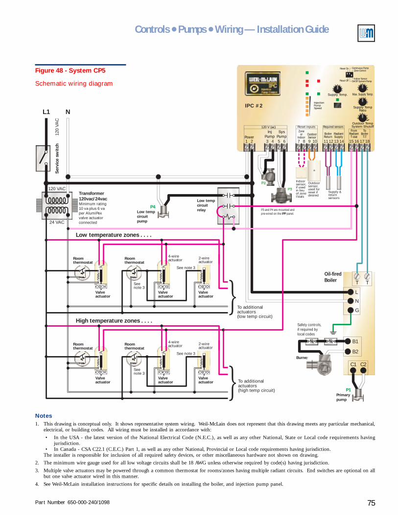
Part Number 650-000-240/1098 75
Controls ● Pumps ● Wiring — Installation Guide
Indoorsensor,if usedin lieuof zonet'stats
L1 N
T
C1
B2
T
C2
B1
L
N
G
P1
P4
120 VAC
120
VAC
Ser
vice
sw
itch
Roomthermostat
Roomthermostat
Roomthermostat
Roomthermostat
Valveactuator
Valveactuator
Valveactuator
Valveactuator
Valveactuator
Valveactuator
See note 3
See note 3
Seenote 3
Seenote 3
2-wireactuator
2-wireactuator
4-wireactuator
4-wireactuator
To additionalactuators(high temp circuit)
To additionalactuators(low temp circuit)
Primarypump
Low tempcircuitpump
Burner
Safety controls,if required bylocal codes
Oil-firedBoiler
24 VAC
Transformer120vac/24vacMinimum rating10 va plus 6 vaper AlumiPexvalve actuatorconnected
Supply Temp.
Outdoor TempSystem Shutoff
InjectionPumpSpeed
InjPump
SysPumpPower
120 V (ac)
31 2 5 64
Required sensorsZone
orIndoor
BoilerReturn
RadiantSupply
OutdoorSensor
7 118 129 1310 14
FromRadiantT-stat
ToBoiler
T-T15 16 17 18
Max. Supply Temp.
Supply TempRatio
Reset Off
Reset On
On/Off System PumpIndoor Sensor
Zone ControlContinuous Pump
Reset inputs
P2
P3
P3 and P4 are mounted andpre-wired on the panel.IPP
Outdoorsensor,used forreset ifdesired
Supply &returnsensors
IPC #2
Low temperature zones . . . .
High temperature zones . . . .
Low tempcircuitrelay
Figure 48 - System CP5
Schematic wiring diagram
Notes1. This drawing is conceptual only. It shows representative system wiring. Weil-McLain does not represent that this drawing meets any particular mechanical,
electrical, or building codes. All wiring must be installed in accordance with:
• In the USA - the latest version of the National Electrical Code (N.E.C.), as well as any other National, State or Local code requirements havingjurisdiction.
• In Canada - CSA C22.1 (C.E.C.) Part 1, as well as any other National, Provincial or Local code requirements having jurisdiction.The installer is responsible for inclusion of all required safety devices, or other miscellaneous hardware not shown on drawing.
2. The minimum wire gauge used for all low voltage circuits shall be 18 AWG unless otherwise required by code(s) having jurisdiction.
3. Multiple valve actuators may be powered through a common thermostat for rooms/zones having multiple radiant circuits. End switches are optional on allbut one valve actuator wired in this manner.
4. See Weil-McLain installation instructions for specific details on installing the boiler, and injection pump panel.
Part Number 650-000-240/109876
AlumiPAlumiPAlumiPAlumiPAlumiPeeeeexxxxx® ® ® ® ® Radiant TRadiant TRadiant TRadiant TRadiant Tubingubingubingubingubing
Radiant heating system examplesXIISystem CP-6
(pages 78 – 79)Radiant heating and domestic water heating withconventional boiler - DHW as a secondary circuit
Purpose• Provide radiant heating and domestic water heating (with optional domestic priority). The
control and injection pump regulate radiant circuit supply temperature and maintainminimum boiler return temperature.
Pumps and piping
Primary circuit
• The primary pump can be as supplied with the boiler or purchased separately.
• Residential packaged boilers may have the pump mounted on the return piping at the boiler.The pump can be used in this location provided the expansion tank or compression tank andfill line are correctly located.
Radiant circuits
• The Injection Pump Panel (IPP) includes the injection pump and the radiant circuit pump.(For applications larger than the capacity of the IPP, use multiple IPP panels or use an IPCInjection Pump control with an injection pump and radiant circuit pump sized for the flowrates and pressure drops needed.)
• System CP-6 shows two manifolds location for the radiant circuits. The same piping designcan be used for multiple manifolds.
• Manifold valve actuators are optional, but recommended as discussed in Zoning radiantheating systems, section IV of this Guide. When actuators are not used, provide the call forheat signal to the IPC (24 volt or 120 volt signal to terminals 15 and 16) through a zonethermostat or a dry contact that closes on a call for heat. Alternatively, use an indoor sensoror zone control.
Water heater circuit
• Provide a pump with the domestic water heater, sized to give the required flow through theheater for the supply water temperature available.
• Pipe the domestic water circuit as the first branch off the primary circuit. This assures thehottest possible supply water temperature.
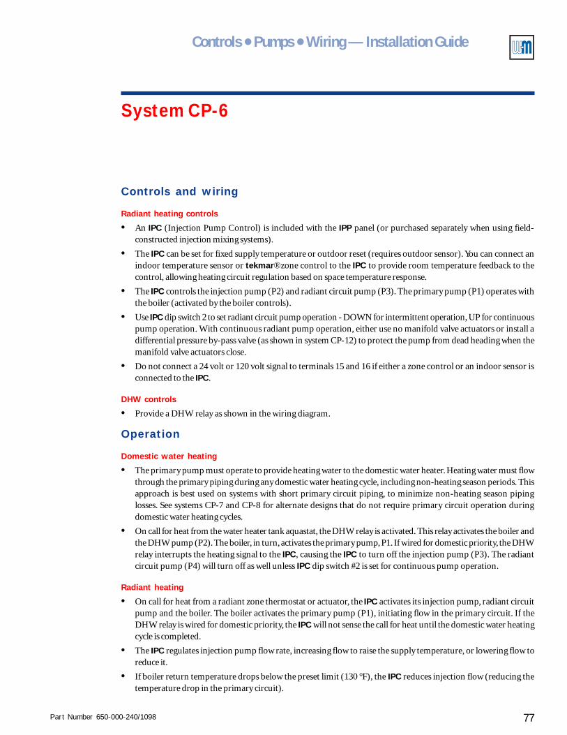
Part Number 650-000-240/1098 77
Controls ● Pumps ● Wiring — Installation Guide
System CP-6
Controls and wiring
Radiant heating controls
• An IPC (Injection Pump Control) is included with the IPP panel (or purchased separately when using field-constructed injection mixing systems).
• The IPC can be set for fixed supply temperature or outdoor reset (requires outdoor sensor). You can connect anindoor temperature sensor or tekmar® zone control to the IPC to provide room temperature feedback to thecontrol, allowing heating circuit regulation based on space temperature response.
• The IPC controls the injection pump (P2) and radiant circuit pump (P3). The primary pump (P1) operates withthe boiler (activated by the boiler controls).
• Use IPC dip switch 2 to set radiant circuit pump operation - DOWN for intermittent operation, UP for continuouspump operation. With continuous radiant pump operation, either use no manifold valve actuators or install adifferential pressure by-pass valve (as shown in system CP-12) to protect the pump from dead heading when themanifold valve actuators close.
• Do not connect a 24 volt or 120 volt signal to terminals 15 and 16 if either a zone control or an indoor sensor isconnected to the IPC.
DHW controls
• Provide a DHW relay as shown in the wiring diagram.
Operation
Domestic water heating
• The primary pump must operate to provide heating water to the domestic water heater. Heating water must flowthrough the primary piping during any domestic water heating cycle, including non-heating season periods. Thisapproach is best used on systems with short primary circuit piping, to minimize non-heating season pipinglosses. See systems CP-7 and CP-8 for alternate designs that do not require primary circuit operation duringdomestic water heating cycles.
• On call for heat from the water heater tank aquastat, the DHW relay is activated. This relay activates the boiler andthe DHW pump (P2). The boiler, in turn, activates the primary pump, P1. If wired for domestic priority, the DHWrelay interrupts the heating signal to the IPC, causing the IPC to turn off the injection pump (P3). The radiantcircuit pump (P4) will turn off as well unless IPC dip switch #2 is set for continuous pump operation.
Radiant heating
• On call for heat from a radiant zone thermostat or actuator, the IPC activates its injection pump, radiant circuitpump and the boiler. The boiler activates the primary pump (P1), initiating flow in the primary circuit. If theDHW relay is wired for domestic priority, the IPC will not sense the call for heat until the domestic water heatingcycle is completed.
• The IPC regulates injection pump flow rate, increasing flow to raise the supply temperature, or lowering flow toreduce it.
• If boiler return temperature drops below the preset limit (130 °F), the IPC reduces injection flow (reducing thetemperature drop in the primary circuit).
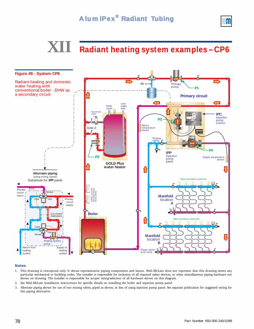
Part Number 650-000-240/109878
AlumiPAlumiPAlumiPAlumiPAlumiPeeeeexxxxx® ® ® ® ® Radiant TRadiant TRadiant TRadiant TRadiant Tubingubingubingubingubing
Fill
Boiler
P1
P3
Primary circuit
Returntemperaturesensor
Primarypump
Saf
ety
cont
rols
(as
requ
ired
by
loca
l cod
es)
P4
Manifold
Alocation
Manifold
Blocation
Purge valves& air vents
Supply temperaturesensor
Valve actuators optional
Valve actuators optional
Purgingvalves
GOLD Pluswater heater
P2
note 2
flow/checkvalve
Alternate piping
IPPSubstitute for panel(using mixing valves)
Heating systempump
Return fromheatingsystem
Supply toheatingsystem
Primarycircuitsupply
Primarycircuitreturn
Hot
Hot
Mixed
Mixed
Cold
2 to 4 pipediameters
Cold
IPCInjectionpumpcontrol
IPPInjectionpumppanel
DHWoutlet
coldwaterinlet
Figure 49 - System CP6
Radiant heating and domesticwater heating withconventional boiler - DHW asa secondary circuit
XII Radiant heating system examples – CP6
Notes1. This drawing is conceptual only. It shows representative piping components and layout. Weil-McLain does not represent that this drawing meets any
particular mechanical or building codes. The installer is responsible for inclusion of all required safety devices, or other miscellaneous piping hardware notshown on drawing. The installer is responsible for proper sizing/selection of all hardware shown on this diagram.
2. See Weil-McLain installation instructions for specific details on installing the boiler and injection pump panel.
3. Alternate piping shown for use of two mixing valves, piped as shown, in lieu of using injection pump panel. See separate publication for suggested wiring forthis piping alternative.
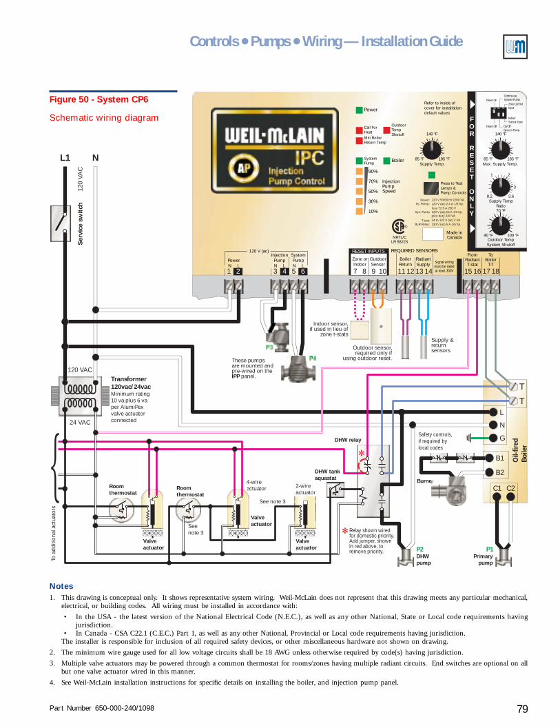
Part Number 650-000-240/1098 79
Controls ● Pumps ● Wiring — Installation Guide
2-wireactuator
4-wireactuator
LR 58223NRTL/C
OutdoorTempShutoff
Press to TestLamps &Pump Controls
Refer to inside ofcover for installationdefault values
BoilerSupply Temp. Max. Supply Temp.
Supply TempRatio
Outdoor TempSystem Shutoff
185 °F 185 °F
100 °F
85 °F 85 °F
40 °F
0.2 3.6
3
21
140 °F 140 °F
70 °F
InjectionPumpSpeed
10
30
90
70
50
SystemPump
Min BoilerReturn Temp
Call ForHeat
%
%
%
%
%
Power
REQUIRED SENSORSRESET INPUTS
Zone orIndoor
InjectionPumpN L
SystemPumpN L
PowerN L
120 V (ac)
BoilerReturn
FromRadiantT-stat
ToBoiler
T-T
Made inCanada
RadiantSupply
OutdoorSensor Signal wiring
must be ratedat least 300V
Power: 120 V 50/60 Hz 1500 VA120 V (ac) 2.4 A 1/5 hp.
120 V (ac) 5 A 1/6 hp.
120 V (ac) 10 A 1/3 hp.
24 to 120 V (ac) 2 VA
fuse T2.5 A 250 V
pilot duty 240 VA
Inj. Pump:
Sys. Pump
T-stat:BLR Relay:
®
3 7 11 151 8 12 162 5 9 13 176 10 14 184
FOR
RESET
ONLY
1 2 3
Reset Off
Reset On
On/OffSystem Pump
IndoorSensor Input
Zone ControlInput
ContinuousSystem Pump
L1 N
T
C1
B2
T
C2
B1
L
N
G
120 VAC
120
VAC
Ser
vice
sw
itch
P3
P4These pumpsare mounted andpre-wired on the
panel.IPP
Outdoor sensor,required only if
using outdoor reset.
Supply &returnsensors
Burner
Safety controls,if required bylocal codes
Relay shown wiredfor domestic priority.Add jumper, shownin red above, toremove priority.
Oil-
fired
Boile
r
Indoor sensor,if used in lieu of
zone t-stats
24 VAC
Transformer120vac/24vacMinimum rating10 va plus 6 vaper AlumiPexvalve actuatorconnected
Roomthermostat
Roomthermostat
Valveactuator
Valveactuator
DHW tankaquastat
DHW relay
See note 3
Seenote 3
To a
dditi
onal
act
uato
rs
Valveactuator P1P2
Primarypump
DHWpump
Figure 50 - System CP6
Schematic wiring diagram
Notes1. This drawing is conceptual only. It shows representative system wiring. Weil-McLain does not represent that this drawing meets any particular mechanical,
electrical, or building codes. All wiring must be installed in accordance with:
• In the USA - the latest version of the National Electrical Code (N.E.C.), as well as any other National, State or Local code requirements havingjurisdiction.
• In Canada - CSA C22.1 (C.E.C.) Part 1, as well as any other National, Provincial or Local code requirements having jurisdiction.The installer is responsible for inclusion of all required safety devices, or other miscellaneous hardware not shown on drawing.
2. The minimum wire gauge used for all low voltage circuits shall be 18 AWG unless otherwise required by code(s) having jurisdiction.
3. Multiple valve actuators may be powered through a common thermostat for rooms/zones having multiple radiant circuits. End switches are optional on allbut one valve actuator wired in this manner.
4. See Weil-McLain installation instructions for specific details on installing the boiler, and injection pump panel.
Part Number 650-000-240/109880
AlumiPAlumiPAlumiPAlumiPAlumiPeeeeexxxxx® ® ® ® ® Radiant TRadiant TRadiant TRadiant TRadiant Tubingubingubingubingubing
Radiant heating system examplesXIISystem CP-7
(pages 82 – 83)Radiant heating and domestic water heating withGV boiler - DHW as a secondary circuit
Purpose• Provide radiant heating and domestic water heating (with optional domestic priority). The
control and injection pump regulate radiant circuit supply temperature and maintainminimum boiler return temperature.
Pumps and piping
Primary circuit
• System CP-7 uses the integral pump in the GV boiler for primary loop circulation. If a higherflow rate is required, pipe the GV boiler and water heater on a secondary circuit and providea separate pump for the primary circuit.
Radiant heating circuits
• The Injection Pump Panel (IPP) includes the injection pump and the radiant circuit pump.(For applications larger than the capacity of the IPP, use multiple IPP panels or use an IPCInjection Pump Control with an injection pump and radiant circuit pump sized for the flowrates and pressure drops needed.)
• System CP-7 shows two manifold locations for the radiant circuits. The same piping designcan be used for multiple manifolds.
• Manifold valve actuators are optional, but recommended as discussed in Zoning radiantheating systems, section IV of this Guide. When actuators are not used, provide the call forheat signal to the IPC (24 volt or 120 volt signal to terminals 15 and 16) through a zonethermostat or a dry contact that closes on a call for heat. Alternatively, use an indoor sensoror zone control.
Water heater circuit
• Provide a pump with the domestic water heater, sized to give the required flow through theheater for the supply water temperature available.
• Pipe the domestic water circuit as the first branch off of the primary. This assures the hottestpossible supply water temperature.
Part Number 650-000-240/1098 81
Controls ● Pumps ● Wiring — Installation Guide
System CP-7
Controls and wiring
Radiant heating controls
• An IPC (Injection Pump Control) is included with the IPP panel (or purchased separately when using field-constructed injection mixing systems).
• The IPC can be set for fixed supply temperature or outdoor reset (requires outdoor sensor). You can connect anindoor temperature sensor or tekmar® zone control to the IPC to provide room temperature feedback to thecontrol, allowing heating circuit regulation based on space temperature response.
• The IPC controls the injection pump (P2) and radiant circuit pump (P3). The primary pump (P1) is integral to theGV boiler, and is activated by the boiler controls.
• Use IPC dip switch 2 to set radiant circuit pump operation - DOWN for intermittent operation, UP for continuouspump operation. With continuous radiant pump operation, either use no manifold valve actuators or install adifferential pressure by-pass valve (as shown in system CP-12) to protect the pump from dead heading when themanifold valve actuators close.
• Do not connect a 24 volt or 120 volt signal to terminals 15 and 16 if either a zone control or an indoor sensor isconnected to the IPC.
DHW controls
• Provide a DHW relay, as shown in the wiring diagram.
Operation
Domestic water heating
• The primary pump (P1, integral to the GV boiler) must operate to provide heating water to the domestic waterheater. Heating water must flow through the primary piping during any domestic water heating cycle, includingnon-heating season periods. This approach is best used on systems with short primary circuit piping, to minimizenon-heating season piping losses. See systems CP-7 and CP-8 for alternate designs that do not require primarycircuit operation during domestic water heating cycles.
• On call for heat from the water heater tank aquastat, the DHW relay is activated. This relay activates the boiler andthe DHW pump (P2). The boiler, in turn, activates the primary pump (P1). If wired for domestic priority, theDHW relay interrupts the heating signal to the IPC, causing the IPC to turn off the injection pump (P3). Theradiant circuit pump (P4) will turn off as well unless IPC dip switch #2 is set for continuous pump operation.
Radiant heating
• On call for heat from a radiant zone thermostat or actuator, the IPC activates its injection pump (P3), radiantcircuit pump (P4) and the boiler. The boiler activates the primary pump (P1), initiating flow in the primary. If theDHW relay is wired for domestic priority, the IPC will not sense the call for heat until the domestic water heatingcycle is completed.
• The IPC regulates injection pump flow rate, increasing flow to raise the supply temperature, or lowering flow toreduce it.
• If boiler return temperature drops below the preset limit (130 °F), the IPC reduces injection flow (reducing thetemperature drop in the primary circuit).
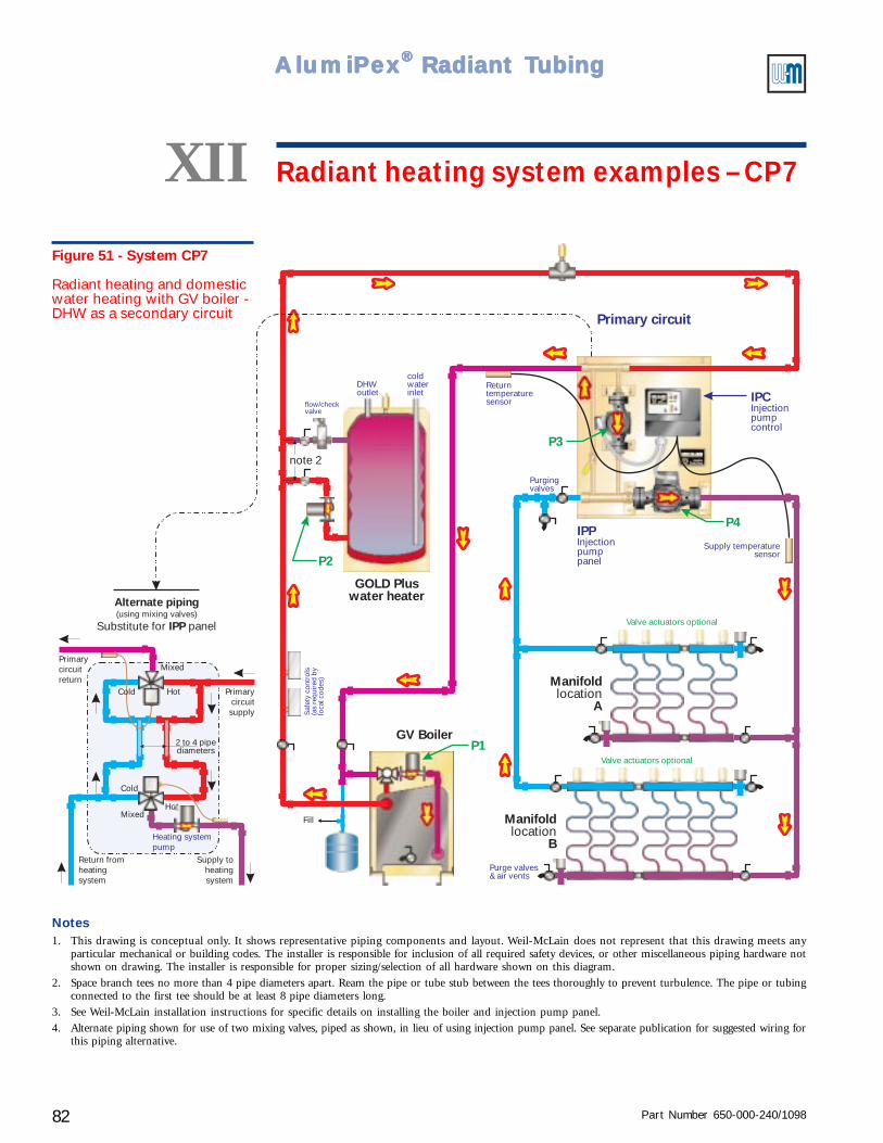
Part Number 650-000-240/109882
AlumiPAlumiPAlumiPAlumiPAlumiPeeeeexxxxx® ® ® ® ® Radiant TRadiant TRadiant TRadiant TRadiant Tubingubingubingubingubing
GOLD Pluswater heater
Fill
GV BoilerP1
P3
P2
Primary circuitS
afet
y co
ntro
ls(a
s re
quir
ed b
ylo
cal c
odes
)
Returntemperaturesensor
note 2
flow/checkvalve
P4
Manifold
Alocation
Manifold
Blocation
Purge valves& air vents
Supply temperaturesensor
Valve actuators optional
Valve actuators optional
Purgingvalves
Alternate piping
IPPSubstitute for panel(using mixing valves)
Heating systempump
Return fromheatingsystem
Supply toheatingsystem
Primarycircuitsupply
Primarycircuitreturn
Hot
Hot
Mixed
Mixed
Cold
2 to 4 pipediameters
Cold
IPCInjectionpumpcontrol
IPPInjectionpumppanel
coldwaterinlet
DHWoutlet
Figure 51 - System CP7
Radiant heating and domesticwater heating with GV boiler -DHW as a secondary circuit
XII Radiant heating system examples – CP7
Notes1. This drawing is conceptual only. It shows representative piping components and layout. Weil-McLain does not represent that this drawing meets any
particular mechanical or building codes. The installer is responsible for inclusion of all required safety devices, or other miscellaneous piping hardware notshown on drawing. The installer is responsible for proper sizing/selection of all hardware shown on this diagram.
2. Space branch tees no more than 4 pipe diameters apart. Ream the pipe or tube stub between the tees thoroughly to prevent turbulence. The pipe or tubingconnected to the first tee should be at least 8 pipe diameters long.
3. See Weil-McLain installation instructions for specific details on installing the boiler and injection pump panel.
4. Alternate piping shown for use of two mixing valves, piped as shown, in lieu of using injection pump panel. See separate publication for suggested wiring forthis piping alternative.
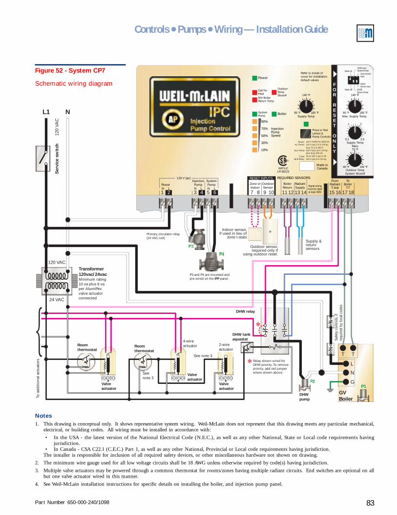
Part Number 650-000-240/1098 83
Controls ● Pumps ● Wiring — Installation Guide
2-wireactuator
4-wireactuator
T T
L
N
GP2P1
LR 58223NRTL/C
OutdoorTempShutoff
Press to TestLamps &Pump Controls
Refer to inside ofcover for installationdefault values
BoilerSupply Temp. Max. Supply Temp.
Supply TempRatio
Outdoor TempSystem Shutoff
185 °F 185 °F
100 °F
85 °F 85 °F
40 °F
0.2 3.6
3
21
140 °F 140 °F
70 °F
InjectionPumpSpeed
10
30
90
70
50
SystemPump
Min BoilerReturn Temp
Call ForHeat
%
%
%
%
%
Power
REQUIRED SENSORSRESET INPUTS
Zone orIndoor
InjectionPumpN L
SystemPumpN L
PowerN L
120 V (ac)
BoilerReturn
FromRadiantT-stat
ToBoiler
T-T
Made inCanada
RadiantSupply
OutdoorSensor Signal wiring
must be ratedat least 300V
Power: 120 V 50/60 Hz 1500 VA120 V (ac) 2.4 A 1/5 hp.
120 V (ac) 5 A 1/6 hp.
120 V (ac) 10 A 1/3 hp.
24 to 120 V (ac) 2 VA
fuse T2.5 A 250 V
pilot duty 240 VA
Inj. Pump:
Sys. Pump
T-stat:BLR Relay:
®
3 7 11 151 8 12 162 5 9 13 176 10 14 184
FOR
RESET
ONLY
1 2 3
Reset Off
Reset On
On/OffSystem Pump
IndoorSensor Input
Zone ControlInput
ContinuousSystem Pump
L1 N
120 VAC
120
VAC
Ser
vice
sw
itch
P3
P4
P3 and P4 are mounted andpre-wired on the panel.IPP
Primary circulator relay(24 VAC coil)
Outdoor sensor,required only if
using outdoor reset.
Supply &returnsensors
Indoor sensor,if used in lieu of
zone t-stats
24 VAC
Transformer120vac/24vacMinimum rating10 va plus 6 vaper AlumiPexvalve actuatorconnected
Roomthermostat
Roomthermostat
Valveactuator
Valveactuator
DHW tankaquastat
DHWpump
DHW relay
See note 3
Seenote 3
To a
dditi
onal
act
uato
rs
Valveactuator
Safe
ty c
ontro
ls, i
fre
quire
d by
loca
l cod
es
GVBoiler
Relay shown wired forDHW priority. To removepriority, add red jumperwhere shown above.
Figure 52 - System CP7
Schematic wiring diagram
Notes1. This drawing is conceptual only. It shows representative system wiring. Weil-McLain does not represent that this drawing meets any particular mechanical,
electrical, or building codes. All wiring must be installed in accordance with:
• In the USA - the latest version of the National Electrical Code (N.E.C.), as well as any other National, State or Local code requirements havingjurisdiction.
• In Canada - CSA C22.1 (C.E.C.) Part 1, as well as any other National, Provincial or Local code requirements having jurisdiction.The installer is responsible for inclusion of all required safety devices, or other miscellaneous hardware not shown on drawing.
2. The minimum wire gauge used for all low voltage circuits shall be 18 AWG unless otherwise required by code(s) having jurisdiction.
3. Multiple valve actuators may be powered through a common thermostat for rooms/zones having multiple radiant circuits. End switches are optional on allbut one valve actuator wired in this manner.
4. See Weil-McLain installation instructions for specific details on installing the boiler, and injection pump panel.
Part Number 650-000-240/109884
AlumiPAlumiPAlumiPAlumiPAlumiPeeeeexxxxx® ® ® ® ® Radiant TRadiant TRadiant TRadiant TRadiant Tubingubingubingubingubing
Radiant heating system examplesXIISystem CP-8
(pages 86 – 87)Radiant heating and domestic water heating withconventional boiler - independent DHW operation
Purpose• Provide radiant heating and domestic water heating (with optional domestic priority). The
control and injection pump regulate radiant circuit supply temperature and maintainminimum boiler return temperature.
• This system allows domestic water heating without flow in the primary circuit, reducingpiping losses during non-heating season periods.
Pumps and piping
Primary circuit
• The primary pump can be as supplied with the boiler or purchased separately.
• Residential packaged boilers may have the pump mounted on the return piping at the boiler.The pump can be used in this location provided the expansion tank or compression tank andfill line are correctly located.
Radiant circuits
• The Injection Pump Panel (IPP) includes the injection pump and the radiant circuit pump.(For applications larger than the capacity of the IPP, use multiple IPP panels or use an IPCInjection Pump Control with an injection pump and radiant circuit pump sized for the flowrates and pressure drops needed.)
• System CP-8 shows two manifold locations for the radiant circuits. The same piping designcan be used for multiple manifolds.
• Manifold valve actuators are optional, but recommended as discussed in Zoning radiantheating systems, section IV of this Guide. When actuators are not used, provide the call forheat signal to the IPC (24 volt or 120 volt signal to terminals 15 and 16) through a zonethermostat or a dry contact that closes on a call for heat. Alternatively, use an indoor sensoror zone control.
Water heater circuit
• Provide a pump with the domestic water heater, sized to give the required flow through theheater for the supply water temperature available.
• Include a flow/check valve in the primary and water heater circuits, as illustrated, to preventflow short circuiting.
• Connect the DHW supply directly off of the boiler supply piping. This assures the hottestpossible supply water temperature. Connect the DHW return to the boiler return piping.
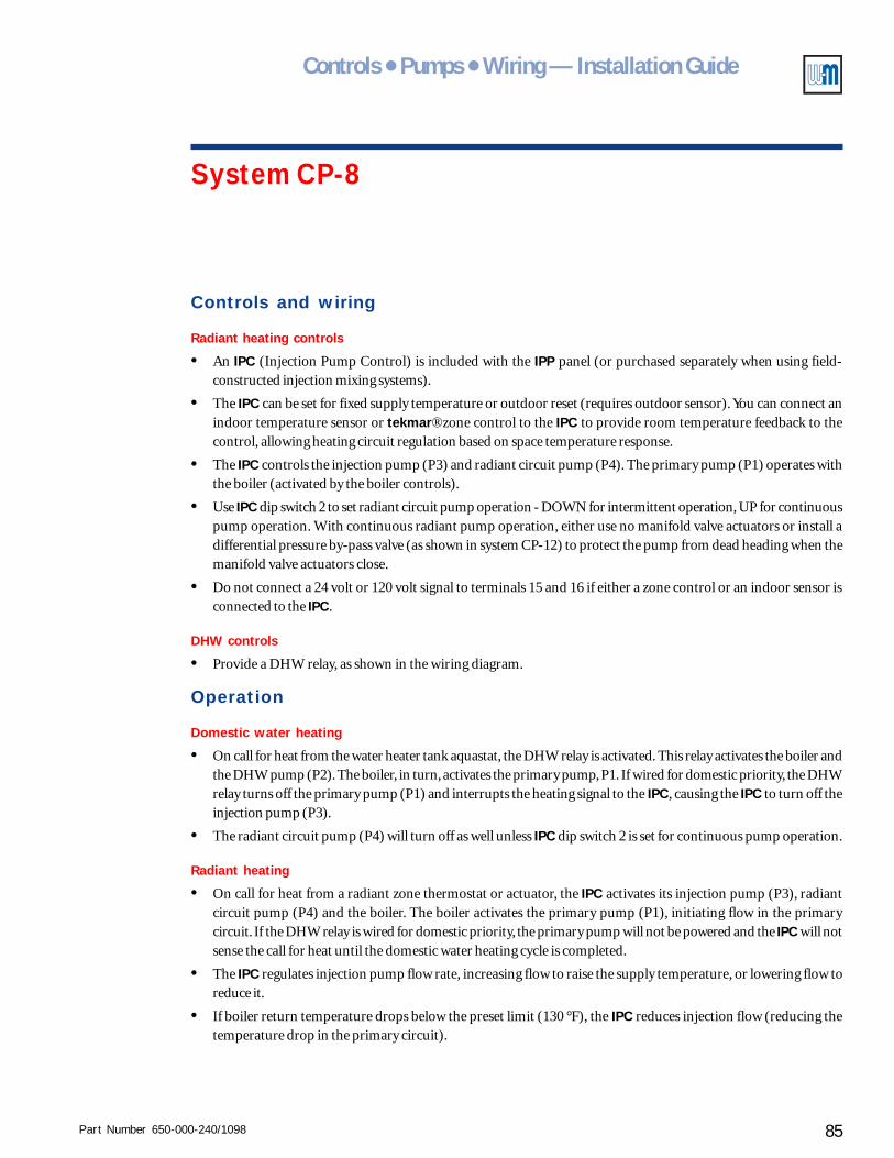
Part Number 650-000-240/1098 85
Controls ● Pumps ● Wiring — Installation Guide
System CP-8
Controls and wiring
Radiant heating controls
• An IPC (Injection Pump Control) is included with the IPP panel (or purchased separately when using field-constructed injection mixing systems).
• The IPC can be set for fixed supply temperature or outdoor reset (requires outdoor sensor). You can connect anindoor temperature sensor or tekmar® zone control to the IPC to provide room temperature feedback to thecontrol, allowing heating circuit regulation based on space temperature response.
• The IPC controls the injection pump (P3) and radiant circuit pump (P4). The primary pump (P1) operates withthe boiler (activated by the boiler controls).
• Use IPC dip switch 2 to set radiant circuit pump operation - DOWN for intermittent operation, UP for continuouspump operation. With continuous radiant pump operation, either use no manifold valve actuators or install adifferential pressure by-pass valve (as shown in system CP-12) to protect the pump from dead heading when themanifold valve actuators close.
• Do not connect a 24 volt or 120 volt signal to terminals 15 and 16 if either a zone control or an indoor sensor isconnected to the IPC.
DHW controls
• Provide a DHW relay, as shown in the wiring diagram.
Operation
Domestic water heating
• On call for heat from the water heater tank aquastat, the DHW relay is activated. This relay activates the boiler andthe DHW pump (P2). The boiler, in turn, activates the primary pump, P1. If wired for domestic priority, the DHWrelay turns off the primary pump (P1) and interrupts the heating signal to the IPC, causing the IPC to turn off theinjection pump (P3).
• The radiant circuit pump (P4) will turn off as well unless IPC dip switch 2 is set for continuous pump operation.
Radiant heating
• On call for heat from a radiant zone thermostat or actuator, the IPC activates its injection pump (P3), radiantcircuit pump (P4) and the boiler. The boiler activates the primary pump (P1), initiating flow in the primarycircuit. If the DHW relay is wired for domestic priority, the primary pump will not be powered and the IPC will notsense the call for heat until the domestic water heating cycle is completed.
• The IPC regulates injection pump flow rate, increasing flow to raise the supply temperature, or lowering flow toreduce it.
• If boiler return temperature drops below the preset limit (130 °F), the IPC reduces injection flow (reducing thetemperature drop in the primary circuit).
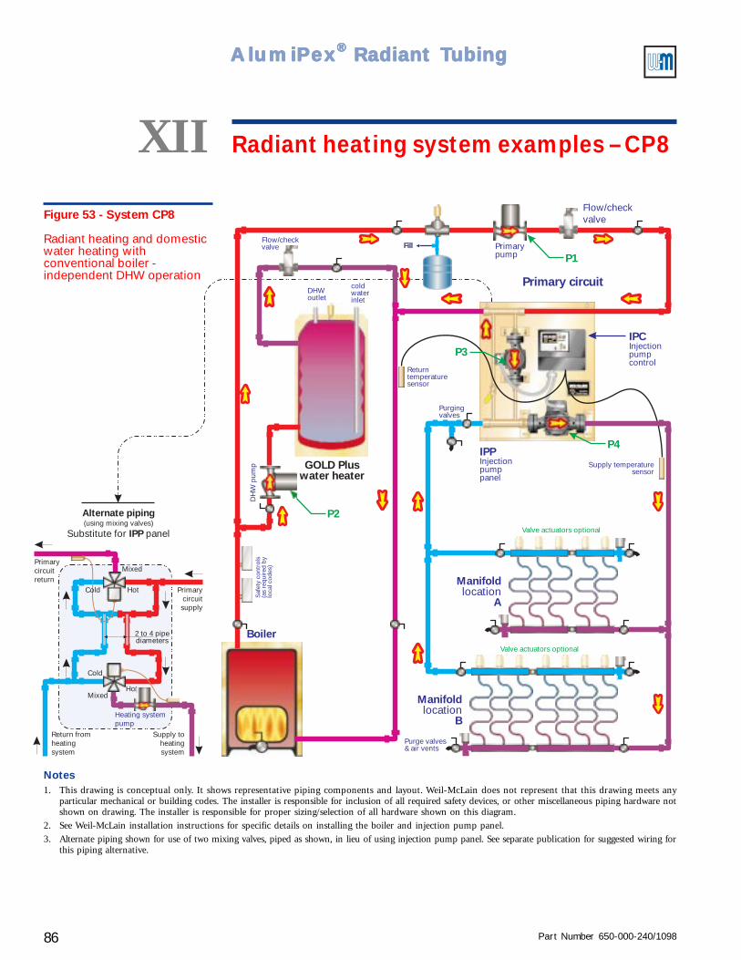
Part Number 650-000-240/109886
AlumiPAlumiPAlumiPAlumiPAlumiPeeeeexxxxx® ® ® ® ® Radiant TRadiant TRadiant TRadiant TRadiant Tubingubingubingubingubing
Fill
Boiler
P1
P2
P3IPCInjectionpumpcontrol
Primary circuit
Returntemperaturesensor
Primarypump
coldwaterinlet
DHWoutlet
DH
W p
ump GOLD Plus
water heater
Saf
ety
cont
rols
(as
requ
ired
by
loca
l cod
es)
Flow/checkvalve
Flow/checkvalve
P4IPPInjectionpumppanel
Manifold
Alocation
Manifold
Blocation
Purge valves& air vents
Supply temperaturesensor
Valve actuators optional
Valve actuators optional
Purgingvalves
Alternate piping
IPPSubstitute for panel(using mixing valves)
Heating systempump
Return fromheatingsystem
Supply toheatingsystem
Primarycircuitsupply
Primarycircuitreturn
Hot
Hot
Mixed
Mixed
Cold
2 to 4 pipediameters
Cold
Figure 53 - System CP8
Radiant heating and domesticwater heating withconventional boiler -independent DHW operation
XII Radiant heating system examples – CP8
Notes1. This drawing is conceptual only. It shows representative piping components and layout. Weil-McLain does not represent that this drawing meets any
particular mechanical or building codes. The installer is responsible for inclusion of all required safety devices, or other miscellaneous piping hardware notshown on drawing. The installer is responsible for proper sizing/selection of all hardware shown on this diagram.
2. See Weil-McLain installation instructions for specific details on installing the boiler and injection pump panel.
3. Alternate piping shown for use of two mixing valves, piped as shown, in lieu of using injection pump panel. See separate publication for suggested wiring forthis piping alternative.
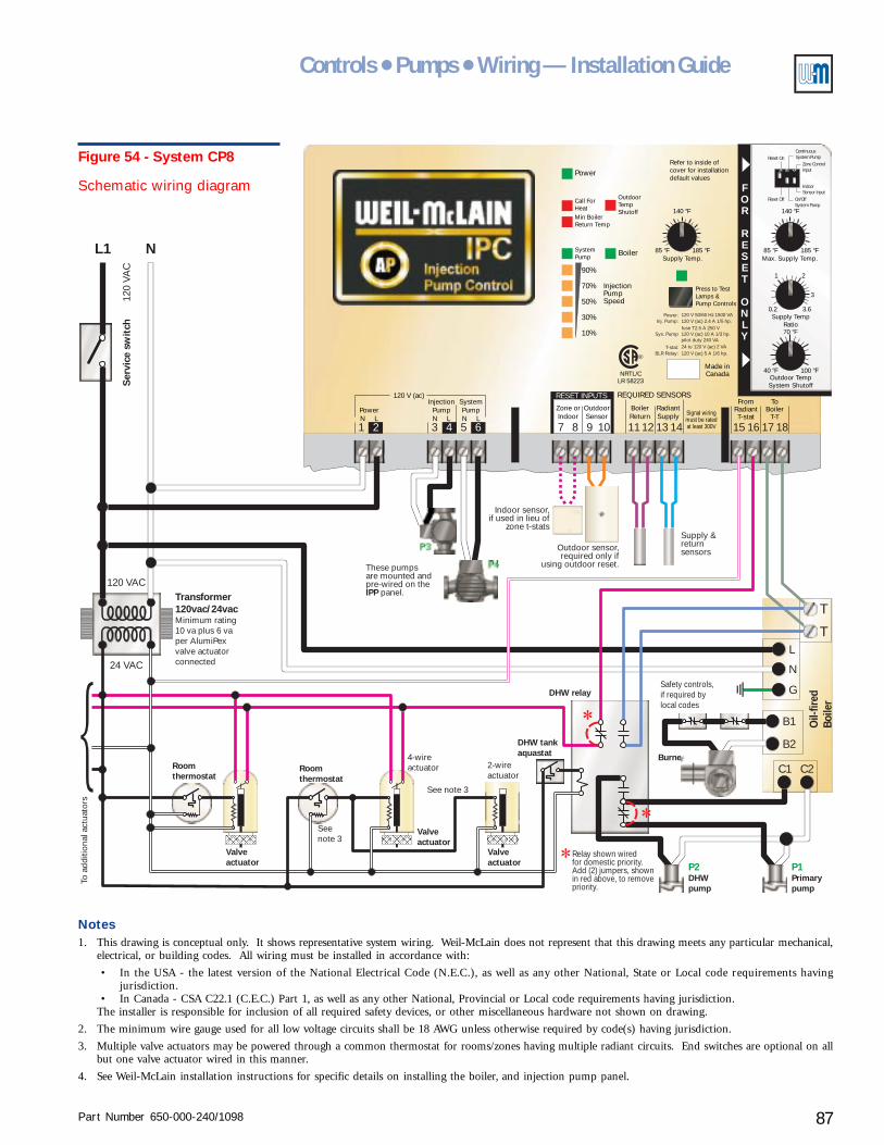
Part Number 650-000-240/1098 87
Controls ● Pumps ● Wiring — Installation Guide
2-wireactuator
4-wireactuator
LR 58223NRTL/C
OutdoorTempShutoff
Press to TestLamps &Pump Controls
Refer to inside ofcover for installationdefault values
BoilerSupply Temp. Max. Supply Temp.
Supply TempRatio
Outdoor TempSystem Shutoff
185 °F 185 °F
100 °F
85 °F 85 °F
40 °F
0.2 3.6
3
21
140 °F 140 °F
70 °F
InjectionPumpSpeed
10
30
90
70
50
SystemPump
Min BoilerReturn Temp
Call ForHeat
%
%
%
%
%
Power
REQUIRED SENSORSRESET INPUTS
Zone orIndoor
InjectionPumpN L
SystemPumpN L
PowerN L
120 V (ac)
BoilerReturn
FromRadiantT-stat
ToBoiler
T-T
Made inCanada
RadiantSupply
OutdoorSensor Signal wiring
must be ratedat least 300V
Power: 120 V 50/60 Hz 1500 VA120 V (ac) 2.4 A 1/5 hp.
120 V (ac) 5 A 1/6 hp.
120 V (ac) 10 A 1/3 hp.
24 to 120 V (ac) 2 VA
fuse T2.5 A 250 V
pilot duty 240 VA
Inj. Pump:
Sys. Pump
T-stat:BLR Relay:
®
3 7 11 151 8 12 162 5 9 13 176 10 14 184
FOR
RESET
ONLY
1 2 3
Reset Off
Reset On
On/OffSystem Pump
IndoorSensor Input
Zone ControlInput
ContinuousSystem Pump
L1 N
T
C1
B2
T
C2
B1
L
N
G
120 VAC
120
VAC
Ser
vice
sw
itch
P3
P4These pumpsare mounted andpre-wired on the
panel.IPP
Outdoor sensor,required only if
using outdoor reset.
Supply &returnsensors
Burner
Safety controls,if required bylocal codes
Relay shown wiredfor domestic priority.Add (2) jumpers, shownin red above, to removepriority.
Oil-
fired
Boile
r
Indoor sensor,if used in lieu of
zone t-stats
24 VAC
Transformer120vac/24vacMinimum rating10 va plus 6 vaper AlumiPexvalve actuatorconnected
Roomthermostat
Roomthermostat
Valveactuator
Valveactuator
DHW tankaquastat
DHW relay
See note 3
Seenote 3
To a
dditi
onal
act
uato
rs
Valveactuator P1P2
Primarypump
DHWpump
Figure 54 - System CP8
Schematic wiring diagram
Notes1. This drawing is conceptual only. It shows representative system wiring. Weil-McLain does not represent that this drawing meets any particular mechanical,
electrical, or building codes. All wiring must be installed in accordance with:
• In the USA - the latest version of the National Electrical Code (N.E.C.), as well as any other National, State or Local code requirements havingjurisdiction.
• In Canada - CSA C22.1 (C.E.C.) Part 1, as well as any other National, Provincial or Local code requirements having jurisdiction.The installer is responsible for inclusion of all required safety devices, or other miscellaneous hardware not shown on drawing.
2. The minimum wire gauge used for all low voltage circuits shall be 18 AWG unless otherwise required by code(s) having jurisdiction.
3. Multiple valve actuators may be powered through a common thermostat for rooms/zones having multiple radiant circuits. End switches are optional on allbut one valve actuator wired in this manner.
4. See Weil-McLain installation instructions for specific details on installing the boiler, and injection pump panel.
Part Number 650-000-240/109888
AlumiPAlumiPAlumiPAlumiPAlumiPeeeeexxxxx® ® ® ® ® Radiant TRadiant TRadiant TRadiant TRadiant Tubingubingubingubingubing
Radiant heating system examplesXIISystem CP-9
(pages 90 – 91)
Purpose• Provide radiant heating and domestic water heating with domestic priority. The control and
injection pump regulate radiant circuit supply temperature and maintain minimum boilerreturn temperature.
• This system provides domestic water heating without flow in the primary circuit, reducingpiping losses during non-heating season periods.
Pumps and piping
Primary circuit
• The GV boiler integral pump must provide flow for the water heater and primary circuits.
Radiant circuits
• The Injection Pump Panel (IPP) includes the injection pump and the radiant circuit pump.(For applications larger than the capacity of the IPP, use multiple IPP panels or use an IPCInjection Pump Control with an injection pump and radiant circuit pump sized for the flowrates and pressure drops needed.)
• System CP-9 shows two manifold location for the radiant circuits. The same piping designcan be used for multiple manifolds.
• Manifold valve actuators are optional, but recommended as discussed in Zoning radiantheating systems, section IV of this Guide. When actuators are not used, provide the call forheat signal to the IPC (24 volt or 120 volt signal to terminals 15 and 16) through a zonethermostat or a dry contact that closes on a call for heat.
Water heater circuit
• The 3-way diverting valve is normally open to the radiant heating circuit (primary). It directsflow through either the primary or domestic water circuit.
Radiant heating and priority domestic water heatingwith GV boiler – DHW through diverting valve
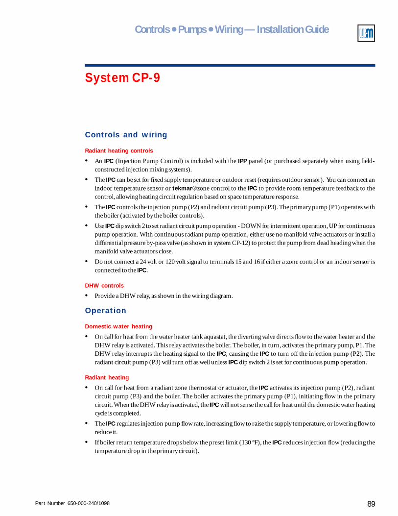
Part Number 650-000-240/1098 89
Controls ● Pumps ● Wiring — Installation Guide
System CP-9
Controls and wiring
Radiant heating controls
• An IPC (Injection Pump Control) is included with the IPP panel (or purchased separately when using field-constructed injection mixing systems).
• The IPC can be set for fixed supply temperature or outdoor reset (requires outdoor sensor). You can connect anindoor temperature sensor or tekmar® zone control to the IPC to provide room temperature feedback to thecontrol, allowing heating circuit regulation based on space temperature response.
• The IPC controls the injection pump (P2) and radiant circuit pump (P3). The primary pump (P1) operates withthe boiler (activated by the boiler controls).
• Use IPC dip switch 2 to set radiant circuit pump operation - DOWN for intermittent operation, UP for continuouspump operation. With continuous radiant pump operation, either use no manifold valve actuators or install adifferential pressure by-pass valve (as shown in system CP-12) to protect the pump from dead heading when themanifold valve actuators close.
• Do not connect a 24 volt or 120 volt signal to terminals 15 and 16 if either a zone control or an indoor sensor isconnected to the IPC.
DHW controls
• Provide a DHW relay, as shown in the wiring diagram.
Operation
Domestic water heating
• On call for heat from the water heater tank aquastat, the diverting valve directs flow to the water heater and theDHW relay is activated. This relay activates the boiler. The boiler, in turn, activates the primary pump, P1. TheDHW relay interrupts the heating signal to the IPC, causing the IPC to turn off the injection pump (P2). Theradiant circuit pump (P3) will turn off as well unless IPC dip switch 2 is set for continuous pump operation.
Radiant heating
• On call for heat from a radiant zone thermostat or actuator, the IPC activates its injection pump (P2), radiantcircuit pump (P3) and the boiler. The boiler activates the primary pump (P1), initiating flow in the primarycircuit. When the DHW relay is activated, the IPC will not sense the call for heat until the domestic water heatingcycle is completed.
• The IPC regulates injection pump flow rate, increasing flow to raise the supply temperature, or lowering flow toreduce it.
• If boiler return temperature drops below the preset limit (130 °F), the IPC reduces injection flow (reducing thetemperature drop in the primary circuit).
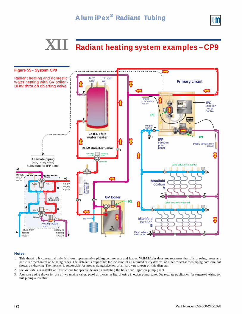
Part Number 650-000-240/109890
AlumiPAlumiPAlumiPAlumiPAlumiPeeeeexxxxx® ® ® ® ® Radiant TRadiant TRadiant TRadiant TRadiant Tubingubingubingubingubing
Fill
GV Boiler
GOLD Pluswater heater
DHW diverter valve
P1
P2
Primary circuitS
afet
y co
ntro
ls(a
s re
quir
ed b
ylo
cal c
odes
)
common
normallyclosed
normallyopen
Returntemperaturesensor
P3
Manifold
Alocation
Manifold
Blocation
Purge valves& air vents
Supply temperaturesensor
Valve actuators optional
Valve actuators optional
Purgingvalves
Alternate piping
IPPSubstitute for panel(using mixing valves)
Heating systempump
Return fromheatingsystem
Supply toheatingsystem
Primarycircuitsupply
Primarycircuitreturn
Hot
Hot
Mixed
Mixed
Cold
2 to 4 pipediameters
Cold
IPCInjectionpumpcontrol
IPPInjectionpumppanel
DHWoutlet
cold waterinlet
Figure 55 - System CP9
Radiant heating and domesticwater heating with GV boiler -DHW through diverting valve
XII Radiant heating system examples – CP9
Notes1. This drawing is conceptual only. It shows representative piping components and layout. Weil-McLain does not represent that this drawing meets any
particular mechanical or building codes. The installer is responsible for inclusion of all required safety devices, or other miscellaneous piping hardware notshown on drawing. The installer is responsible for proper sizing/selection of all hardware shown on this diagram.
2. See Weil-McLain installation instructions for specific details on installing the boiler and injection pump panel.
3. Alternate piping shown for use of two mixing valves, piped as shown, in lieu of using injection pump panel. See separate publication for suggested wiring forthis piping alternative.
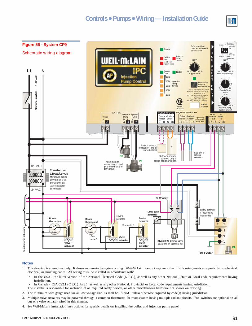
Part Number 650-000-240/1098 91
Controls ● Pumps ● Wiring — Installation Guide
2-wireactuator
4-wireactuator
T T
H
N
G
P1
LR 58223NRTL/C
OutdoorTempShutoff
Press to TestLamps &Pump Controls
Refer to inside ofcover for installationdefault values
BoilerSupply Temp. Max. Supply Temp.
Supply TempRatio
Outdoor TempSystem Shutoff
185 °F 185 °F
100 °F
85 °F 85 °F
40 °F
0.2 3.6
3
21
140 °F 140 °F
70 °F
InjectionPumpSpeed
10
30
90
70
50
SystemPump
Min BoilerReturn Temp
Call ForHeat
%
%
%
%
%
Power
REQUIRED SENSORSRESET INPUTS
Zone orIndoor
InjectionPumpN L
SystemPumpN L
PowerN L
120 V (ac)
BoilerReturn
FromRadiantT-stat
ToBoiler
T-T
Made inCanada
RadiantSupply
OutdoorSensor Signal wiring
must be ratedat least 300V
Power: 120 V 50/60 Hz 1500 VA120 V (ac) 2.4 A 1/5 hp.
120 V (ac) 5 A 1/6 hp.
120 V (ac) 10 A 1/3 hp.
24 to 120 V (ac) 2 VA
fuse T2.5 A 250 V
pilot duty 240 VA
Inj. Pump:
Sys. Pump
T-stat:BLR Relay:
®
3 7 11 151 8 12 162 5 9 13 176 10 14 184
FOR
RESET
ONLY
1 2 3
Reset Off
Reset On
On/OffSystem Pump
IndoorSensor Input
Zone ControlInput
ContinuousSystem Pump
L1 N
120 VAC
120
VAC
Ser
vice
sw
itch
P2
P3These pumpsare mounted andpre-wired on the
panel.IPP
Outdoor sensor,required only if
using outdoor reset.
Supply &returnsensors
Indoor sensor,(if used in lieu of
zone t-stats)
24 VAC
Transformer120vac/24vacMinimum rating10 va plus 6 vaper AlumiPexvalve actuatorconnected
Roomthermostat
Roomthermostat
Valveactuator
Valveactuator
DHW tankaquastat
24VAC DHW diverter valve(energized on call for DHW)
DHW relay
See note 3
Seenote 3
To a
dditi
onal
act
uato
rs
Valveactuator
Safety controls,if required bylocal codes
GV Boiler
Figure 56 - System CP9
Schematic wiring diagram
Notes1. This drawing is conceptual only. It shows representative system wiring. Weil-McLain does not represent that this drawing meets any particular mechanical,
electrical, or building codes. All wiring must be installed in accordance with:
• In the USA - the latest version of the National Electrical Code (N.E.C.), as well as any other National, State or Local code requirements havingjurisdiction.
• In Canada - CSA C22.1 (C.E.C.) Part 1, as well as any other National, Provincial or Local code requirements having jurisdiction.The installer is responsible for inclusion of all required safety devices, or other miscellaneous hardware not shown on drawing.
2. The minimum wire gauge used for all low voltage circuits shall be 18 AWG unless otherwise required by code(s) having jurisdiction.
3. Multiple valve actuators may be powered through a common thermostat for rooms/zones having multiple radiant circuits. End switches are optional on allbut one valve actuator wired in this manner.
4. See Weil-McLain installation instructions for specific details on installing the boiler, and injection pump panel.
Part Number 650-000-240/109892
AlumiPAlumiPAlumiPAlumiPAlumiPeeeeexxxxx® ® ® ® ® Radiant TRadiant TRadiant TRadiant TRadiant Tubingubingubingubingubing
Radiant heating system examplesXIISystem CP-10
(pages 94 – 97)Radiant heating, domestic water heating andbaseboard heating with conventional boiler
Purpose• Provide multiple heating functions - radiant heating and baseboard heating plus domestic
water heating (with optional domestic priority). The control and injection pump regulateradiant circuit supply temperature and help maintain minimum boiler return temperature.
• This system provides domestic water heating without flow in the primary circuit, reducingpiping losses during non-heating season periods.
• Two versions are shown – one for baseboard zoning with zone valves (CP-10a) and the otherfor baseboard zoning with pumps (CP-10b).
Pumps and piping
Primary circuit
• The primary pump can be as supplied with the boiler or purchased separately.
• Residential packaged boilers may have the pump mounted on the return piping at the boiler.The pump can be used in this location provided the expansion tank or compression tank andfill line are correctly located.
Radiant circuits
• The Injection Pump Panel (IPP) includes the injection pump and the radiant circuit pump.(For applications larger than the capacity of the IPP, use multiple IPP panels or use an IPCInjection Pump Control with an injection pump and radiant circuit pump sized for the flowrates and pressure drops needed.)
• System CP-10 shows two manifold locations for the radiant circuits. The same piping designcan be used for multiple manifolds.
• Manifold valve actuators are optional, but recommended as discussed in Zoning radiantheating systems, section IV of this Guide. When actuators are not used, provide the call forheat signal to the IPC (24 volt or 120 volt signal to terminals 15 and 16) through a zonethermostat or a dry contact that closes on a call for heat.
Water heater circuit
• Provide a pump with the domestic water heater, sized to give the required flow through theheater for the supply water temperature available.
• Connect the DHW supply directly off of the boiler supply piping. This assures the hottestpossible supply water temperature. Connect the DHW return to the boiler return piping.
• Include a flow/check valve in the primary and water heater circuits, as illustrated, to preventflow short circuiting.
Baseboard circuits
• The system illustration shows several options for baseboard circuit piping. Provide thepumps needed for the baseboards. Each baseboard branch circuit off of the primary willrequire at least one pump, even if zoning with zone valves. Use flow/check valves in thebaseboard circuits as illustrated. A flow/check is required in every loop when zoning withpumps. A flow/check is required on the return piping when the piping is above the primaryunless a thermal trap is provided as shown.
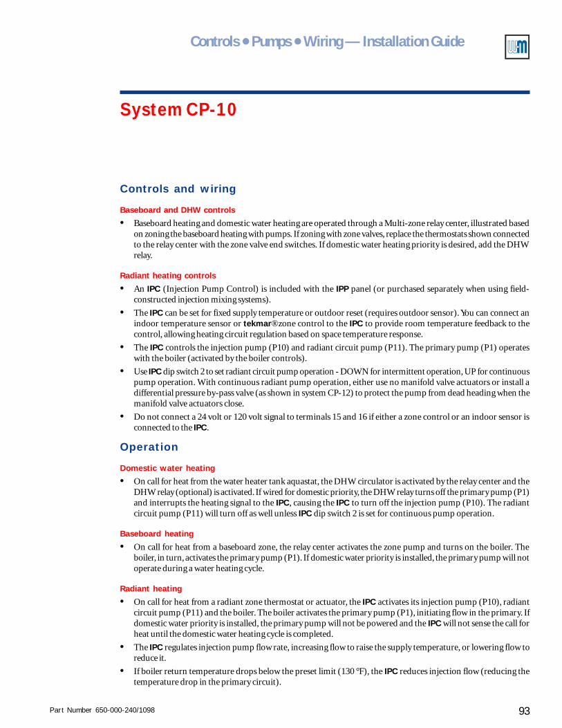
Part Number 650-000-240/1098 93
Controls ● Pumps ● Wiring — Installation Guide
System CP-10
Controls and wiring
Baseboard and DHW controls
• Baseboard heating and domestic water heating are operated through a Multi-zone relay center, illustrated basedon zoning the baseboard heating with pumps. If zoning with zone valves, replace the thermostats shown connectedto the relay center with the zone valve end switches. If domestic water heating priority is desired, add the DHWrelay.
Radiant heating controls
• An IPC (Injection Pump Control) is included with the IPP panel (or purchased separately when using field-constructed injection mixing systems).
• The IPC can be set for fixed supply temperature or outdoor reset (requires outdoor sensor). You can connect anindoor temperature sensor or tekmar® zone control to the IPC to provide room temperature feedback to thecontrol, allowing heating circuit regulation based on space temperature response.
• The IPC controls the injection pump (P10) and radiant circuit pump (P11). The primary pump (P1) operateswith the boiler (activated by the boiler controls).
• Use IPC dip switch 2 to set radiant circuit pump operation - DOWN for intermittent operation, UP for continuouspump operation. With continuous radiant pump operation, either use no manifold valve actuators or install adifferential pressure by-pass valve (as shown in system CP-12) to protect the pump from dead heading when themanifold valve actuators close.
• Do not connect a 24 volt or 120 volt signal to terminals 15 and 16 if either a zone control or an indoor sensor isconnected to the IPC.
Operation
Domestic water heating
• On call for heat from the water heater tank aquastat, the DHW circulator is activated by the relay center and theDHW relay (optional) is activated. If wired for domestic priority, the DHW relay turns off the primary pump (P1)and interrupts the heating signal to the IPC, causing the IPC to turn off the injection pump (P10). The radiantcircuit pump (P11) will turn off as well unless IPC dip switch 2 is set for continuous pump operation.
Baseboard heating
• On call for heat from a baseboard zone, the relay center activates the zone pump and turns on the boiler. Theboiler, in turn, activates the primary pump (P1). If domestic water priority is installed, the primary pump will notoperate during a water heating cycle.
Radiant heating
• On call for heat from a radiant zone thermostat or actuator, the IPC activates its injection pump (P10), radiantcircuit pump (P11) and the boiler. The boiler activates the primary pump (P1), initiating flow in the primary. Ifdomestic water priority is installed, the primary pump will not be powered and the IPC will not sense the call forheat until the domestic water heating cycle is completed.
• The IPC regulates injection pump flow rate, increasing flow to raise the supply temperature, or lowering flow toreduce it.
• If boiler return temperature drops below the preset limit (130 °F), the IPC reduces injection flow (reducing thetemperature drop in the primary circuit).

Part Number 650-000-240/109894
AlumiPAlumiPAlumiPAlumiPAlumiPeeeeexxxxx® ® ® ® ® Radiant TRadiant TRadiant TRadiant TRadiant Tubingubingubingubingubing
GOLD Pluswater heater
Fill
P1
P11
P10
P2
IPP Injectionpump panel
IPCInjectionpumpcontrol
Manifold
Alocation
Manifold
Blocation
Primary circuit
Purge valves& air vents
Supply temperaturesensor
Valve actuators optional
Valve actuators optional
flow/checkvalve
flow/checkvalve
Boiler
Saf
ety
cont
rols
(as
requ
ired
bylo
cal c
odes
)
Purgingvalves
Purgingvalves
Purgingvalves
P3
P3
P3
Baseboard zones(when above primary)
Baseboard zones(when below primary)
note 2
Zonevalves
Zone valves
Zonevalves
note 2
Thermaltrap - 18" min.
Alternate piping to circuit at left, usingflow/check valve on return line in placeof thermal trap
Use minimum 18" thermal trapas alternate to flow/check valve
Returntemperaturesensor
Alternate piping
IPPSubstitute for panel(using mixing valves)
Heating systempump
Return fromheatingsystem
Supply toheatingsystem
Primarycircuitsupply
Primarycircuitreturn
Hot
Hot
Mixed
Mixed
Cold
2 to 4 pipediameters
Cold
DHWoutlet
coldwaterinlet
Figure 57 - System CP10a
Radiant heating, domesticwater heating and baseboardheating with conventionalboiler - baseboard zoning withzone valves
XII Radiant heating system examples – CP10
Notes1. This drawing is conceptual only. It shows representative piping components and layout. Weil-McLain does
not represent that this drawing meets any particular mechanical or building codes. The installer is responsiblefor inclusion of all required safety devices, or other miscellaneous piping hardware not shown on drawing.The installer is responsible for proper sizing/selection of all hardware shown on this diagram.
2. Space branch tees no more than 4 pipe diameters apart. Ream the pipe or tube stub between the teesthoroughly to prevent turbulence. The pipe or tubing connected to the first tee should be at least 8 pipediameters long.
3. See Weil-McLain installation instructions for specific details on installing the boiler and injection pumppanel.
4. Alternate piping shown for use of two mixing valves, piped as shown, in lieu of using injection pump panel.See separate publication for suggested wiring for this piping alternative.
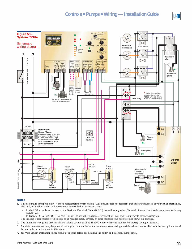
Part Number 650-000-240/1098 95
Controls ● Pumps ● Wiring — Installation Guide
Supply Temp.
Outdoor TempSystem Shutoff
InjectionPumpSpeed
InjPump
SysPumpPower
120 V (ac)
31 2 5 64
Required sensorsZone
orIndoor
BoilerReturn
RadiantSupply
OutdoorSensor
7 118 129 1310 14
FromRadiantT-stat
ToBoiler
T-T15 16 17 18
Max. Supply Temp.
Supply TempRatio
Reset Off
Reset On
On/Off System PumpIndoor Sensor
Zone ControlContinuous Pump
Reset inputs
2-wireactuator
4-wireactuator
L1 N
TC1
B2
TC2
B1
L
N
G
120 VAC
120
VAC
Ser
vice
sw
itch
Burner
Safety controls,if required bylocal codes
Oil-firedBoiler
24 VAC
Roomthermostat
Roomthermostat
Valveactuator
Valveactuator
DHW tankaquastat
DHW pump
DHW relay
See note 3
Seenote 3
To a
dditi
onal
act
uato
rs
Valveactuator
P1
P2
Primarypump
P10
P11
P10 and P11 are mounted andpre-wired on the panel.IPP
Outdoorsensor,if used Supply &
return sensors
Transformer120vac/24vacMinimum rating 10 va plus6 va per AlumiPex valveactuator connected, plustotal va load of all zonevalves connected
∗ Relay shown wiredfor domestic priority.Add (2) jumpers, shownin red, to remove priority.
Baseboardthermostats
Zone valves
P3
Baseboardpump
Baseboardrelay
Indoorsensor,if usedin lieuof valveactuators
Figure 58 -System CP10a
Schematicwiring diagram
Notes1. This drawing is conceptual only. It shows representative system wiring. Weil-McLain does not represent that this drawing meets any particular mechanical,
electrical, or building codes. All wiring must be installed in accordance with:
• In the USA - the latest version of the National Electrical Code (N.E.C.), as well as any other National, State or Local code requirements havingjurisdiction.
• In Canada - CSA C22.1 (C.E.C.) Part 1, as well as any other National, Provincial or Local code requirements having jurisdiction.The installer is responsible for inclusion of all required safety devices, or other miscellaneous hardware not shown on drawing.
2. The minimum wire gauge used for all low voltage circuits shall be 18 AWG unless otherwise required by code(s) having jurisdiction.
3. Multiple valve actuators may be powered through a common thermostat for rooms/zones having multiple radiant circuits. End switches are optional on allbut one valve actuator wired in this manner.
4. See Weil-McLain installation instructions for specific details on installing the boiler, and injection pump panel.
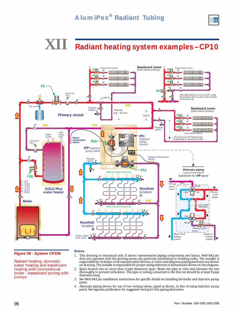
Part Number 650-000-240/109896
AlumiPAlumiPAlumiPAlumiPAlumiPeeeeexxxxx® ® ® ® ® Radiant TRadiant TRadiant TRadiant TRadiant Tubingubingubingubingubing
GOLD Pluswater heater
Fill
P1
P11
P10
P2
Manifold
Alocation
Manifold
Blocation
Primary circuit
Purge valves& air vents
Supply temperaturesensor
Valve actuators optional
Valve actuators optional
flow/checkvalve
flow/checkvalve
Boiler
Saf
ety
cont
rols
(as
requ
ired
bylo
cal c
odes
)
Purgingvalves
P4
P4
P4
P5
P5
P5
P6
P6
P6
Flow/check valves Flow/check valves
Flow/check valves
Returntemperaturesensor
P3
Baseboard zones(when above primary)
Baseboard zones(when below primary)
note 2
note 2
Thermaltrap - 18" min.
Alternate piping to circuit at left, usingflow/check valve on return line in placeof thermal trap
Use minimum 18" thermal trapas alternate to flow/check valve
Returntemperaturesensor
Purgingvalves
Purgingvalves
Alternate piping
IPPSubstitute for panel(using mixing valves)
Heating systempump
Return fromheatingsystem
Supply toheatingsystem
Primarycircuitsupply
Primarycircuitreturn
Hot
Hot
Mixed
Mixed
Cold
2 to 4 pipediameters
Cold
IPP Injectionpump panel
IPCInjectionpumpcontrol
DHWoutlet
coldwaterinlet
Figure 59 - System CP10b
Radiant heating, domesticwater heating and baseboardheating with conventionalboiler - baseboard zoning withpumps
XII Radiant heating system examples – CP10
Notes1. This drawing is conceptual only. It shows representative piping components and layout. Weil-McLain
does not represent that this drawing meets any particular mechanical or building codes. The installer isresponsible for inclusion of all required safety devices, or other miscellaneous piping hardware not shownon drawing. The installer is responsible for proper sizing/selection of all hardware shown on this diagram.
2. Space branch tees no more than 4 pipe diameters apart. Ream the pipe or tube stub between the teesthoroughly to prevent turbulence. The pipe or tubing connected to the first tee should be at least 8 pipediameters long.
3. See Weil-McLain installation instructions for specific details on installing the boiler and injection pumppanel.
4. Alternate piping shown for use of two mixing valves, piped as shown, in lieu of using injection pumppanel. See separate publication for suggested wiring for this piping alternative.
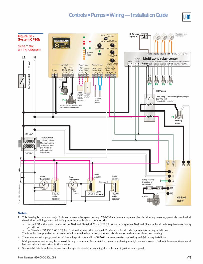
Part Number 650-000-240/1098 97
Controls ● Pumps ● Wiring — Installation Guide
2-wireactuator
4-wireactuator
L1 N
T C1
B2
T C2
B1
L
N
G
120 VAC
120
VAC
Ser
vice
sw
itch
Burner
Safety controls,if required bylocal codes
Oil-firedBoiler
24 VAC
Transformer120vac/24vacMinimum rating10 va plus 6 vaper AlumiPexvalve actuatorconnected
Roomthermostat
Roomthermostat
Valveactuator
Valveactuator
DHW tankaquastat
Multi-zone relay center
DHW relay - use if DHW priority req’d120 VAC coil(supplied by installer)
DHW pump
See note 3
Seenote 3
To a
dditi
onal
act
uato
rs
Valveactuator
P1
P2 P4 P5 P6
Primarypump
Supply Temp.
Outdoor TempSystem Shutoff
InjectionPumpSpeed
InjPump
SysPumpPower
120 V (ac)
31 2 5 64
Required sensorsZone
orIndoor
BoilerReturn
RadiantSupply
OutdoorSensor
7 118 129 1310 14
FromRadiantT-stat
ToBoiler
T-T15 16 17 18
Max. Supply Temp.
Supply TempRatio
Reset Off
Reset On
On/Off System PumpIndoor Sensor
Zone ControlContinuous Pump
Reset inputs
P10
P11
P10 and P11 are mounted andpre-wired on the panel.IPP
Outdoorsensor,if used Supply &
returnsensors
See control manufacturer's instructions for DHW priority activation
Baseboard zonethermostats
Power
Isolatedboilercontact
T1
T N T T PR PR C1 C1 C2 C2 C3 C3 C4 C4 C5 C5 C6 C6
T1 T3T3T2T2 T4T4 T5 T5 T6 T6
Indoorsensor,if usedin lieuof valveactuators
Figure 60 -System CP10b
Schematicwiring diagram
Notes1. This drawing is conceptual only. It shows representative system wiring. Weil-McLain does not represent that this drawing meets any particular mechanical,
electrical, or building codes. All wiring must be installed in accordance with:
• In the USA - the latest version of the National Electrical Code (N.E.C.), as well as any other National, State or Local code requirements havingjurisdiction.
• In Canada - CSA C22.1 (C.E.C.) Part 1, as well as any other National, Provincial or Local code requirements having jurisdiction.The installer is responsible for inclusion of all required safety devices, or other miscellaneous hardware not shown on drawing.
2. The minimum wire gauge used for all low voltage circuits shall be 18 AWG unless otherwise required by code(s) having jurisdiction.
3. Multiple valve actuators may be powered through a common thermostat for rooms/zones having multiple radiant circuits. End switches are optional on allbut one valve actuator wired in this manner.
4. See Weil-McLain installation instructions for specific details on installing the boiler, and injection pump panel.
Part Number 650-000-240/109898
AlumiPAlumiPAlumiPAlumiPAlumiPeeeeexxxxx® ® ® ® ® Radiant TRadiant TRadiant TRadiant TRadiant Tubingubingubingubingubing
Radiant heating system examplesXIISystem CP-11
(pages 100 – 103)Radiant heating, domestic water heating andbaseboard heating with GV boiler
Purpose• Provide multiple heating functions - radiant heating and baseboard heating plus domestic
water heating (with optional domestic priority). The control and injection pump regulateradiant circuit supply temperature and help maintain minimum boiler return temperature.
• Two versions are shown - one for baseboard zoning with zone valves (CP-11a) and the otherfor baseboard zoning with pumps (CP-11b).
Pumps and piping
Primary circuit
• The GV integral pump provides flow in the primary circuit. If more flow is required, installthe GV boiler as a secondary circuit off the primary and provide an appropriately sizedprimary pump.
Radiant circuits
• The Injection Pump Panel (IPP) includes the injection pump and the radiant circuit pump.(For applications larger than the capacity of the IPP, use multiple IPP panels or use an IPCInjection Pump Control with an injection pump and radiant circuit pump sized for the flowrates and pressure drops needed.)
• System CP-11 shows two manifold locations for the radiant circuits. The same piping designcan be used for multiple manifolds.
• Manifold valve actuators are optional, but recommended as discussed in Zoning radiantheating systems, section IV of this Guide. When actuators are not used, provide the call forheat signal to the IPC (24 volt or 120 volt signal to terminals 15 and 16) through a zonethermostat or a dry contact that closes on a call for heat.
Water heater circuit
• Provide a pump with the domestic water heater, sized to give the required flow through theheater for the supply water temperature available.
• Connect the water heater in the first secondary circuit off of the primary. This assures thehottest available supply water.
Baseboard circuits
• The system illustration shows several options for baseboard circuit piping. Provide the pumpsneeded for the baseboards. Each baseboard branch circuit off of the primary will require atleast one pump, even if zoning with zone valves. Use flow/check valves in the baseboardcircuits as illustrated. A flow/check is required in every loop when zoning with pumps. A flow/check is required on the return piping when the piping is above the primary unless a thermaltrap is provided as shown.
Part Number 650-000-240/1098 99
Controls ● Pumps ● Wiring — Installation Guide
System CP-11
Controls and wiring
Baseboard and water heating controls
• Baseboard heating and domestic water heating are operated through a Multi-zone relay center, illustrated basedon zoning the baseboard heating with pumps. If zoning with zone valves, replace the thermostats shown connectedto the relay center with the zone valve end switches. If domestic water heating priority is desired, add the DHWrelay.
Radiant heating controls
• An IPC (Injection Pump Control) is included with the IPP panel (or purchased separately when using field-constructed injection mixing systems).
• The IPC can be set for fixed supply temperature or outdoor reset (requires outdoor sensor). You can connect anindoor temperature sensor or tekmar® zone control to the IPC to provide room temperature feedback to thecontrol, allowing heating circuit regulation based on space temperature response.
• The IPC controls the injection pump (P10) and radiant circuit pump (P11). The primary pump (P1) is integral tothe GV boiler (activated by the boiler controls).
• Use IPC dip switch 2 to set radiant circuit pump operation - DOWN for intermittent operation, UP for continuouspump operation. With continuous radiant pump operation, either use no manifold valve actuators or install adifferential pressure by-pass valve (as shown in system CP-12) to protect the pump from dead heading when themanifold valve actuators close.
• Do not connect a 24 volt or 120 volt signal to terminals 15 and 16 if either a zone control or an indoor sensor isconnected to the IPC.
Operation
Domestic water heating
• On call for heat from the water heater tank aquastat, the DHW circulator is activated by the relay center and theDHW relay (optional) is activated. If wired for domestic priority, the DHW relay interrupts the heating signal tothe IPC, causing the IPC to turn off the injection pump (P10). The radiant circuit pump (P11) will turn off as wellunless IPC dip switch 2 is set for continuous pump operation.
Baseboard heating
• On call for heat from a baseboard zone, the relay center activates the zone pump and turns on the boiler. Theboiler, in turn, activates the primary pump (P1).
Radiant heating
• On call for heat from a radiant zone thermostat or actuator, the IPC activates its injection pump (P10), radiantcircuit pump (P11) and the boiler. The boiler activates the primary pump (P1), initiating flow in the primary. Ifdomestic water priority is installed, the IPC will not sense the call for heat until the domestic water heating cycle iscompleted.
• The IPC regulates injection pump flow rate, increasing flow to raise the supply temperature, or lowering flow toreduce it.
• If boiler return temperature drops below the preset limit (130 °F), the IPC reduces injection flow (reducing thetemperature drop in the primary circuit).
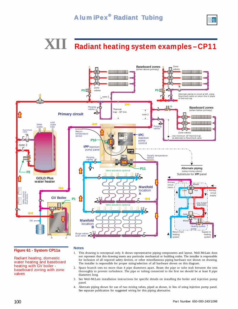
Part Number 650-000-240/1098100
AlumiPAlumiPAlumiPAlumiPAlumiPeeeeexxxxx® ® ® ® ® Radiant TRadiant TRadiant TRadiant TRadiant TubingubingubingubingubingS
afet
y co
ntro
ls(a
s re
quire
d by
loca
l cod
es)
P1
P11
P10
IPP Injectionpump panel
IPCInjectionpumpcontrol
Manifold
Alocation
Manifold
Blocation
Primary circuit
Returntemperaturesensor
Purge valves& air vents
Supply temperaturesensor
Valve actuators optional
Valve actuators optional
Purgingvalves
Fill
GV Boiler
GOLD Pluswater heater
DHWoutlet
coldwaterinlet
P2
note 2
flow/checkvalve
P3
P3
P3
Baseboard zones(when above primary)
Baseboard zones(when below primary)
note 2
Zonevalves
Zonevalves
note 2
Thermaltrap - 18" min.
Alternate piping to circuit at left, usingflow/check valve on return line in placeof thermal trap
Use minimum 18" thermal trapas alternate to flow/check valve
Zone valves
Purgingvalves
Purgingvalves
Alternate piping
IPPSubstitute for panel(using mixing valves)
Heating systempump
Return fromheatingsystem
Supply toheatingsystem
Primarycircuitsupply
Primarycircuitreturn
Hot
Hot
Mixed
Mixed
Cold
2 to 4 pipediameters
Cold
Figure 61 - System CP11a
Radiant heating, domesticwater heating and baseboardheating with GV boiler -baseboard zoning with zonevalves
XII Radiant heating system examples – CP11
Notes1. This drawing is conceptual only. It shows representative piping components and layout. Weil-McLain does
not represent that this drawing meets any particular mechanical or building codes. The installer is responsiblefor inclusion of all required safety devices, or other miscellaneous piping hardware not shown on drawing.The installer is responsible for proper sizing/selection of all hardware shown on this diagram.
2. Space branch tees no more than 4 pipe diameters apart. Ream the pipe or tube stub between the teesthoroughly to prevent turbulence. The pipe or tubing connected to the first tee should be at least 8 pipediameters long.
3. See Weil-McLain installation instructions for specific details on installing the boiler and injection pumppanel.
4. Alternate piping shown for use of two mixing valves, piped as shown, in lieu of using injection pump panel.See separate publication for suggested wiring for this piping alternative.
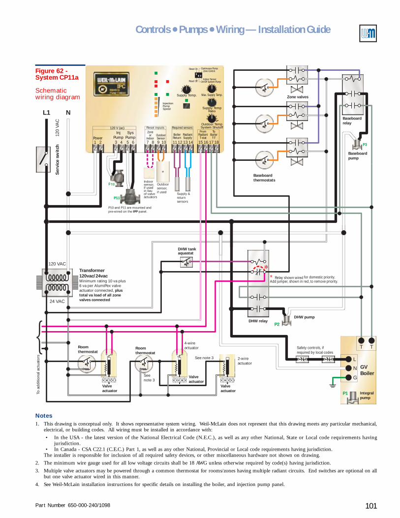
Part Number 650-000-240/1098 101
Controls ● Pumps ● Wiring — Installation Guide
Baseboardthermostats
Zone valves
2-wireactuator
4-wireactuator
L1 N
120 VAC
120
VAC
Ser
vice
sw
itch
24 VAC
Transformer120vac/24vacMinimum rating 10 va plus6 va per AlumiPex valveactuator connected, plustotal va load of all zonevalves connected
Roomthermostat
Roomthermostat
Valveactuator
Valveactuator
See note 3
Seenote 3
To a
dditi
onal
act
uato
rs
Valveactuator
Supply Temp.
Outdoor TempSystem Shutoff
InjectionPumpSpeed
InjPump
SysPumpPower
120 V (ac)
31 2 5 64
Required sensorsZone
orIndoor
BoilerReturn
RadiantSupply
OutdoorSensor
7 118 129 1310 14
FromRadiantT-stat
ToBoiler
T-T15 16 17 18
Max. Supply Temp.
Supply TempRatio
Reset Off
Reset On
On/Off System PumpIndoor Sensor
Zone ControlContinuous Pump
Reset inputs
P10
P11
P3
P10 and P11 are mounted andpre-wired on the panel.IPP
Outdoorsensor,if used Supply &
returnsensors
T T
L
N
G
P1
Safety controls, ifrequired by local codes
GVBoiler
DHW tankaquastat
DHW pump
Integralpump
DHW relay
Baseboardpump
Baseboardrelay
P2
∗ Relay shown wired for domestic priority.Add jumper, shown in red, to remove priority.
Indoorsensor,if usedin lieuof valveactuators
Figure 62 -System CP11a
Schematicwiring diagram
Notes1. This drawing is conceptual only. It shows representative system wiring. Weil-McLain does not represent that this drawing meets any particular mechanical,
electrical, or building codes. All wiring must be installed in accordance with:
• In the USA - the latest version of the National Electrical Code (N.E.C.), as well as any other National, State or Local code requirements havingjurisdiction.
• In Canada - CSA C22.1 (C.E.C.) Part 1, as well as any other National, Provincial or Local code requirements having jurisdiction.The installer is responsible for inclusion of all required safety devices, or other miscellaneous hardware not shown on drawing.
2. The minimum wire gauge used for all low voltage circuits shall be 18 AWG unless otherwise required by code(s) having jurisdiction.
3. Multiple valve actuators may be powered through a common thermostat for rooms/zones having multiple radiant circuits. End switches are optional on allbut one valve actuator wired in this manner.
4. See Weil-McLain installation instructions for specific details on installing the boiler, and injection pump panel.

Part Number 650-000-240/1098102
AlumiPAlumiPAlumiPAlumiPAlumiPeeeeexxxxx® ® ® ® ® Radiant TRadiant TRadiant TRadiant TRadiant TubingubingubingubingubingS
afet
y co
ntro
ls(a
s re
quir
ed b
ylo
cal c
odes
)
P1
P11
P10
Manifold
Alocation
Manifold
Blocation
Primary circuit
Returntemperaturesensor
Purge valves& air vents
Supply temperaturesensor
Valve actuators optional
Valve actuators optional
Purgingvalves
Fill
GV Boiler
GOLD Pluswater heater
P2
note 2
flow/checkvalve
P4
P4
P4
P5
P5
P5
P6
P6
P6
Flow/check valves Flow/check valves
Flow/check valves
P3
Baseboard zones(when above primary)
Baseboard zones(when below primary)
note 2
note 2
Thermaltrap - 18" min.
Alternate piping to circuit at left, usingflow/check valve on return line in placeof thermal trap
Use minimum 18" thermal trapas alternate to flow/check valve
Purgingvalves
Purgingvalves
Alternate piping
IPPSubstitute for panel(using mixing valves)
Heating systempump
Return fromheatingsystem
Supply toheatingsystem
Primarycircuitsupply
Primarycircuitreturn
Hot
Hot
Mixed
Mixed
Cold
2 to 4 pipediameters
Cold
IPP Injectionpump panel
IPCInjectionpumpcontrol
DHWoutlet
coldwaterinlet
Figure 63 - System CP11b
Radiant heating, domesticwater heating and baseboardheating with GV boiler -baseboard zoning with pumps
XII Radiant heating system examples – CP11
Notes1. This drawing is conceptual only. It shows representative piping components and layout. Weil-McLain does
not represent that this drawing meets any particular mechanical or building codes. The installer is responsiblefor inclusion of all required safety devices, or other miscellaneous piping hardware not shown on drawing.The installer is responsible for proper sizing/selection of all hardware shown on this diagram.
2. Space branch tees no more than 4 pipe diameters apart. Ream the pipe or tube stub between the teesthoroughly to prevent turbulence. The pipe or tubing connected to the first tee should be at least 8 pipediameters long.
3. See Weil-McLain installation instructions for specific details on installing the boiler and injection pumppanel.
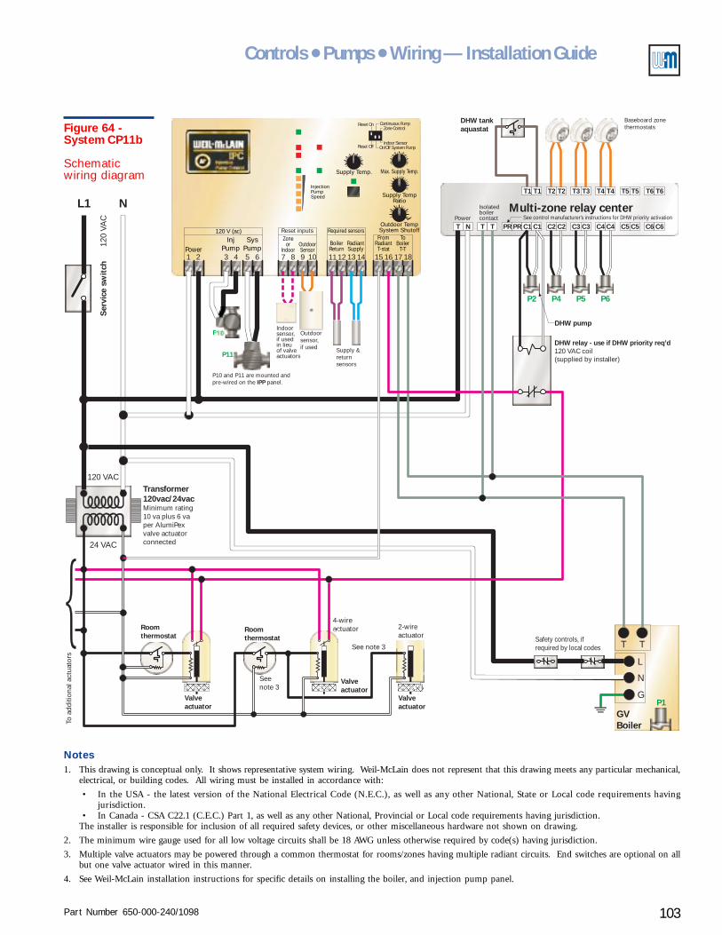
Part Number 650-000-240/1098 103
Controls ● Pumps ● Wiring — Installation Guide
2-wireactuator
4-wireactuator
L1 N
120 VAC
120
VAC
Ser
vice
sw
itch
24 VAC
Transformer120vac/24vacMinimum rating10 va plus 6 vaper AlumiPexvalve actuatorconnected
Roomthermostat
Roomthermostat
Valveactuator
Valveactuator
DHW tankaquastat
Multi-zone relay center
DHW relay - use if DHW priority req’d120 VAC coil(supplied by installer)
DHW pump
See note 3
Seenote 3
To a
dditi
onal
act
uato
rs
Valveactuator
P2 P4 P5 P6
Supply Temp.
Outdoor TempSystem Shutoff
InjectionPumpSpeed
InjPump
SysPumpPower
120 V (ac)
31 2 5 64
Required sensorsZone
orIndoor
BoilerReturn
RadiantSupply
OutdoorSensor
7 118 129 1310 14
FromRadiantT-stat
ToBoiler
T-T15 16 17 18
Max. Supply Temp.
Supply TempRatio
Reset Off
Reset On
On/Off System PumpIndoor Sensor
Zone ControlContinuous Pump
Reset inputs
P10
P11
P10 and P11 are mounted andpre-wired on the panel.IPP
Outdoorsensor,if used Supply &
returnsensors
See control manufacturer's instructions for DHW priority activationPower
Isolatedboilercontact
T1
T N T T PR PR C1 C1 C2 C2 C3 C3 C4 C4 C5 C5 C6 C6
T1 T3T3T2T2 T4T4 T5 T5 T6 T6
T T
L
N
GP1
Safety controls, ifrequired by local codes
GVBoiler
Baseboard zonethermostats
Indoorsensor,if usedin lieuof valveactuators
Figure 64 -System CP11b
Schematicwiring diagram
Notes1. This drawing is conceptual only. It shows representative system wiring. Weil-McLain does not represent that this drawing meets any particular mechanical,
electrical, or building codes. All wiring must be installed in accordance with:
• In the USA - the latest version of the National Electrical Code (N.E.C.), as well as any other National, State or Local code requirements havingjurisdiction.
• In Canada - CSA C22.1 (C.E.C.) Part 1, as well as any other National, Provincial or Local code requirements having jurisdiction.The installer is responsible for inclusion of all required safety devices, or other miscellaneous hardware not shown on drawing.
2. The minimum wire gauge used for all low voltage circuits shall be 18 AWG unless otherwise required by code(s) having jurisdiction.
3. Multiple valve actuators may be powered through a common thermostat for rooms/zones having multiple radiant circuits. End switches are optional on allbut one valve actuator wired in this manner.
4. See Weil-McLain installation instructions for specific details on installing the boiler, and injection pump panel.
Part Number 650-000-240/1098104
AlumiPAlumiPAlumiPAlumiPAlumiPeeeeexxxxx® ® ® ® ® Radiant TRadiant TRadiant TRadiant TRadiant Tubingubingubingubingubing
• System CP-12 shows three manifold locations forthe radiant circuits. The same piping design can beused for multiple manifolds.
• Manifold valve actuators are optional, butrecommended as discussed in Zoning radiantheating systems, section IV of this Guide. Whenactuators are not used, provide the call for heat signalto the IPC (24 volt or 120 volt signal to terminals 15and 16) through a zone thermostat or a dry contactthat closes on a call for heat.
Water heater circuit
• Provide a pump with the domestic water heater, sizedto give the required flow through the heater for thesupply water temperature available.
• Connect the DHW as a secondary circuit directly offof the multiple boiler supply manifold. This assuresthe hottest possible supply water temperature.
Baseboard circuits
• The system illustration shows two options forbaseboard circuit piping (see also system CP-10 foradditional options). Provide the pumps needed forthe baseboards. Each baseboard branch circuit offof the primary will require at least one pump, even ifzoning with zone valves. Use flow/check valves in thebaseboard circuits as illustrated. A flow/check isrequired in every loop when zoning with pumps. Aflow/check is required on the return piping when thepiping is above the primary unless a thermal trap isprovided as shown.
Controls and wiring
Baseboard and domestic water heating controls
• Baseboard heating and domestic water heating areoperated through a Multi-zone relay center,illustrated based on zoning the baseboard heatingwith pumps. If zoning with zone valves, replace the
Radiant heating system examplesXIISystem
CP-12(p.106 – 109)
Radiant heating, domestic water heating and baseboardheating with multiple boilers
Purpose
• Use a multiple boiler system to provide multipleheating functions - radiant heating and baseboardheating plus domestic water heating (with optionaldomestic priority). The control and injection pumpregulate radiant circuit supply temperature and helpmaintain minimum boiler return temperature.
• This system provides domestic water heating withoutflow in the primary circuit, reducing piping lossesduring non-heating season periods. Flow is onlyrequired in the multiple boiler secondary pipingduring domestic water heating cycles.
• Two versions are shown - one for baseboard zoningwith zone valves (CP-12a) and the other forbaseboard zoning with pumps (CP-12b).
Pumps and piping
Primary circuit
• Provide a primary pump sized for the flow needed.
Multiple boiler circuits
• Provide a pump and flow/check valve for each boiler(or use factory-packaged pump, if applicable).
• Residential packaged boilers may have the pumpmounted on the return piping at the boiler. The pumpcan be used in this location provided the expansiontank or compression tank and fill line are correctlylocated.
Radiant heating circuits
• The Injection Pump Panel (IPP) includes the injectionpump and the radiant circuit pump. (For applicationslarger than the capacity of the IPP, use multiple IPPpanels or use an IPC Injection Pump Control with aninjection pump and radiant circuit pump sized forthe flow rates and pressure drops needed.)
Part Number 650-000-240/1098 105
Controls ● Pumps ● Wiring — Installation Guide
System CP-12
thermostats shown connected to the relay center withthe zone valve end switches.
Radiant controls
• An IPC (Injection Pump Control) is included withthe IPP panel (or purchased separately when usingfield-constructed injection mixing systems).
• The IPC can be set for fixed supply temperature oroutdoor reset (requires outdoor sensor). You canconnect an indoor temperature sensor or tekmar®zone control to the IPC to provide room temperaturefeedback to the control, allowing heating circuitregulation based on space temperature response.
• The IPC controls the injection pump (P2) and radiantcircuit pump (P3). The primary pump (P1) operateswith the boiler (activated by the boiler controls).
• Use IPC dip switch 2 to set radiant circuit pumpoperation - DOWN for intermittent operation, UPfor continuous pump operation. With continuousradiant pump operation, either use no manifold valveactuators or install a differential pressure by-passvalve (as shown in system CP-12) to protect the pumpfrom dead heading when the manifold valve actuatorsclose.
• Do not connect a 24 volt or 120 volt signal to terminals15 and 16 if either a zone control or an indoor sensoris connected to the IPC.
DHW controls
• Provide the DHW relay shown is domestic priority isdesired or to prevent flow in the primary pipingduring non-heating season domestic water heatingperiods.
• Multiple boiler controller.
• Install multiple boiler control, as illustrated. Themultiple boiler control shown has provision foractivation of the DHW pump on a signal from theDHW relay.
Operation
Domestic water heating
• On call for heat from the water heater tank aquastat,the DHW relay is activated. The relay activates theboiler and signals the multiple boiler control toactivate the DHW pump. The multiple boiler controlsequences boilers on as needed to meet the demand.If wired for domestic priority, the DHW relay turnsoff the primary pump (P4) and interrupts the heatingsignal to the IPC, causing the IPC to turn off theinjection pump (P12). The radiant circuit pump (P13)will turn off as well unless IPC dip switch 2 is set forcontinuous pump operation.
Baseboard heating
• On call for heat from a baseboard zone, the relaycenter activates the zone pump and sends a call forheat to the multiple boiler control. The multiple boilercontrol, in turn, activates the primary pump (P1)and sequences boilers on as needed to meet demand.If domestic water priority is installed, the primarypump will not operate during a water heating cycle.
Radiant heating
• On call for heat from a radiant zone thermostat oractuator, the IPC activates its injection pump (P10),radiant circuit pump (P11) and sends a call for heatto the multiple boiler control. The multiple boilercontrol activates the primary pump (P1), initiatingflow in the primary, and sequences boilers on asneeded to meet demand. If domestic water priority isinstalled, the primary pump will not be powered andthe IPC will not sense the call for heat until thedomestic water heating cycle is completed.
• The IPC regulates injection pump flow rate, increasingflow to raise the supply temperature, or loweringflow to reduce it.
• If boiler return temperature drops below the presetlimit (130 °F), the IPC reduces injection flow (reducingthe temperature drop in the primary circuit).
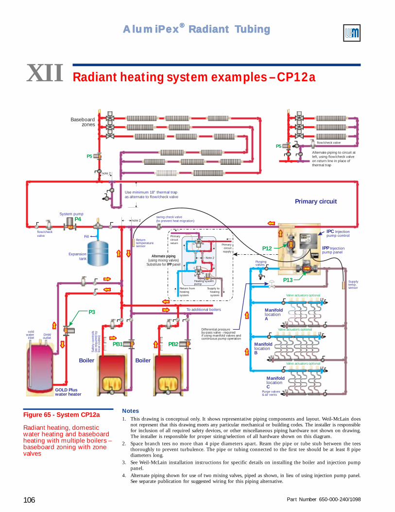
Part Number 650-000-240/1098106
AlumiPAlumiPAlumiPAlumiPAlumiPeeeeexxxxx® ® ® ® ® Radiant TRadiant TRadiant TRadiant TRadiant Tubingubingubingubingubing
Differential pressureby-pass valve - requiredif using manifold valves andcontinuous pump operation
swing check valve(to prevent heat migration)
Heating systempump
Return fromheatingsystem
Supply toheatingsystem
Primarycircuitsupply
Primarycircuitreturn
H
H
M
M
C
C
Note 2Alternate piping
IPP(using mixing valves)
Substitute for panel
GOLD Pluswater heater
DHWoutlet
coldwater
inlet
System pump
Expansiontank
To additional boilers
Fill
P4
P3
PB1 PB2
P13
P12
P5
P5
IPC Injectionpump control
Primary circuit
Baseboardzones
Returntemperaturesensor
Purge valves& air vents
Supplytemp.sensor
Valve actuators optional
Valve actuators optional
Valve actuators optional
note 2
note 2
flow/checkvalve
flow/check valve
Alternate piping to circuit atleft, using flow/check valveon return line in place ofthermal trap
Use minimum 18” thermal trapas alternate to flow/check valve
Boiler Boiler
Saf
ety
cont
rols
(as
requ
ired
by
loca
l cod
es)
Purgingvalves
IPP Injectionpump panel
Manifold
Alocation
Manifold
Blocation
Manifold
Clocation
Figure 65 - System CP12a
Radiant heating, domesticwater heating and baseboardheating with multiple boilers –baseboard zoning with zonevalves
XII Radiant heating system examples – CP12a
Notes1. This drawing is conceptual only. It shows representative piping components and layout. Weil-McLain does
not represent that this drawing meets any particular mechanical or building codes. The installer is responsiblefor inclusion of all required safety devices, or other miscellaneous piping hardware not shown on drawing.The installer is responsible for proper sizing/selection of all hardware shown on this diagram.
2. Space branch tees no more than 4 pipe diameters apart. Ream the pipe or tube stub between the teesthoroughly to prevent turbulence. The pipe or tubing connected to the first tee should be at least 8 pipediameters long.
3. See Weil-McLain installation instructions for specific details on installing the boiler and injection pumppanel.
4. Alternate piping shown for use of two mixing valves, piped as shown, in lieu of using injection pump panel.See separate publication for suggested wiring for this piping alternative.
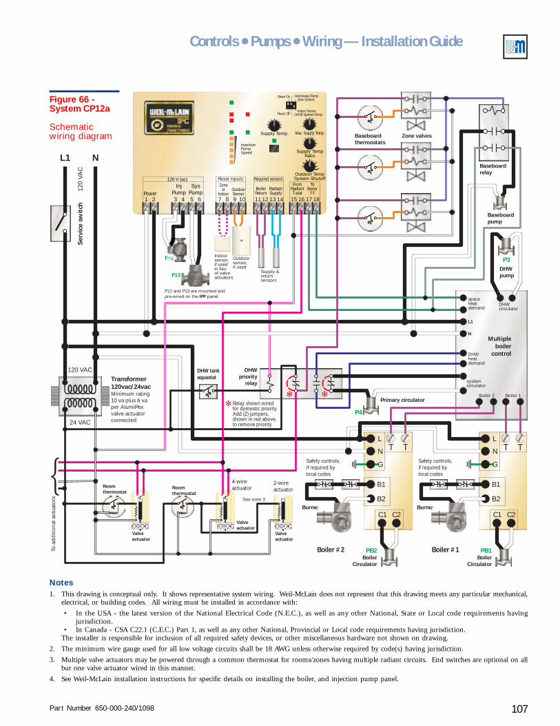
Part Number 650-000-240/1098 107
Controls ● Pumps ● Wiring — Installation Guide
Supply Temp.
Outdoor TempSystem Shutoff
InjectionPumpSpeed
InjPump
SysPumpPower
120 V (ac)
31 2 5 64
Required sensorsZone
orIndoor
BoilerReturn
RadiantSupply
OutdoorSensor
7 118 129 1310 14
FromRadiantT-stat
ToBoiler
T-T15 16 17 18
Max. Supply Temp.
Supply TempRatio
Reset Off
Reset On
On/Off System PumpIndoor Sensor
Zone ControlContinuous Pump
Reset inputs
2-wireactuator
4-wireactuator
L1 N
TT
C1C1
B2B2
TT
C2C2
B1B1
L L
N N
G G
120 VAC
120
VAC
Ser
vice
sw
itch
BurnerBurner
Safety controls,if required bylocal codes
Safety controls,if required bylocal codes
Boiler #1Boiler #2
24 VAC
Transformer120vac/24vacMinimum rating10 va plus 6 vaper AlumiPexvalve actuatorconnected
Roomthermostat
Roomthermostat
Valveactuator
Valveactuator
DHWpump
DHWpriority
relay
Primary circulator
See note 3
To a
dditi
onal
act
uato
rs
Valveactuator
PB1
P4
P3
PB2Boiler
CirculatorBoiler
Circulator
Multipleboiler
control
spaceheatdemand
DHWheatdemand
systemcirculator
Boiler 2 Boiler 1
DHWcirculator
L1
N
P12
P13
P12 and P13 are mounted andpre-wired on the panel.IPP
Outdoorsensor,if used
Supply &returnsensors
Indoorsensor,if usedin lieuof valveactuators
Relay shown wiredfor domestic priority.Add (2) jumpers,shown in red above,to remove priority.
Baseboardpump
Baseboardrelay
Baseboardthermostats
Zone valves
DHW tankaquastat
Figure 66 -System CP12a
Schematicwiring diagram
Notes1. This drawing is conceptual only. It shows representative system wiring. Weil-McLain does not represent that this drawing meets any particular mechanical,
electrical, or building codes. All wiring must be installed in accordance with:
• In the USA - the latest version of the National Electrical Code (N.E.C.), as well as any other National, State or Local code requirements havingjurisdiction.
• In Canada - CSA C22.1 (C.E.C.) Part 1, as well as any other National, Provincial or Local code requirements having jurisdiction.The installer is responsible for inclusion of all required safety devices, or other miscellaneous hardware not shown on drawing.
2. The minimum wire gauge used for all low voltage circuits shall be 18 AWG unless otherwise required by code(s) having jurisdiction.
3. Multiple valve actuators may be powered through a common thermostat for rooms/zones having multiple radiant circuits. End switches are optional on allbut one valve actuator wired in this manner.
4. See Weil-McLain installation instructions for specific details on installing the boiler, and injection pump panel.

Part Number 650-000-240/1098108
AlumiPAlumiPAlumiPAlumiPAlumiPeeeeexxxxx® ® ® ® ® Radiant TRadiant TRadiant TRadiant TRadiant Tubingubingubingubingubing
Differential pressureby-pass valve - requiredif using manifold valves andcontinuous pump operation
swing check valve(to prevent heat migration)
Alternate piping
IPP(using mixing valves)
Substitute for panel
GOLD Pluswater heater
DHWoutlet
coldwater
inlet
System pump
Expansiontank
To additional boilers
Fill
P4
P3
PB1 PB2
P13
P12
P5 P5
P6 P6
P7 P7
Primary circuit
Baseboardzones
Returntemperaturesensor
Purge valves& air vents
Supplytemp.sensor
Valve actuators optional
Valve actuators optional
Valve actuators optional
note 2
note 2
flow/checkvalves
flow/checkvalve
flow/check valve
Alternate piping to circuit atleft, using flow/check valveon return line in place ofthermal trap.
Use minimum 18” thermal trapas alternate to flow/check valve
Boiler Boiler
Saf
ety
cont
rols
(as
requ
ired
by
loca
l cod
es)
Purgingvalves
Manifold
Alocation
Manifold
Blocation
Manifold
Clocation
Heating systempump
Return fromheatingsystem
Supply toheatingsystem
Primarycircuitsupply
Primarycircuitreturn
H
H
M
M
C
C
Note 2
IPC Injectionpump control
IPP Injectionpump panel
Figure 67 - System CP12b
Radiant heating, domesticwater heating and baseboardheating with multiple boilers -baseboard zoning with pumps
XII Radiant heating system examples – CP12b
Notes1. This drawing is conceptual only. It shows representative piping components and layout. Weil-McLain does
not represent that this drawing meets any particular mechanical or building codes. The installer is responsiblefor inclusion of all required safety devices, or other miscellaneous piping hardware not shown on drawing.The installer is responsible for proper sizing/selection of all hardware shown on this diagram.
2. Space branch tees no more than 4 pipe diameters apart. Ream the pipe or tube stub between the teesthoroughly to prevent turbulence. The pipe or tubing connected to the first tee should be at least 8 pipediameters long.
3. See Weil-McLain installation instructions for specific details on installing the boiler and injection pumppanel.
4. Alternate piping shown for use of two mixing valves, piped as shown, in lieu of using injection pump panel.See separate publication for suggested wiring for this piping alternative.
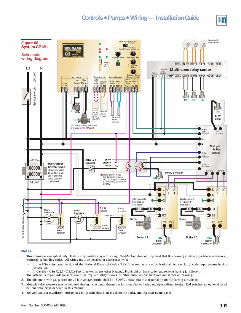
Part Number 650-000-240/1098 109
Controls ● Pumps ● Wiring — Installation Guide
Multi-zone relay centerPower
Isolatedboilercontact
T1
L N T T PR PR C1 C1 C2 C2 C3 C3 C4 C4 C5 C5 C6 C6
T1 T3T3T2T2 T4T4 T5 T5 T6 T6
Supply Temp.
Outdoor TempSystem Shutoff
InjectionPumpSpeed
InjPump
SysPumpPower
120 V (ac)
31 2 5 64
Required sensorsZone
orIndoor
BoilerReturn
RadiantSupply
OutdoorSensor
7 118 129 1310 14
FromRadiantT-stat
ToBoiler
T-T15 16 17 18
Max. Supply Temp.
Supply TempRatio
Reset Off
Reset On
On/Off System PumpIndoor Sensor
Zone ControlContinuous Pump
Reset inputs
2-wireactuator
4-wireactuator
L1 N
TT
C1C1
B2B2
TT
C2C2
B1B1
L L
N N
G G
120 VAC
120
VAC
Ser
vice
sw
itch
BurnerBurner
Safety controls,if required bylocal codes
Safety controls,if required bylocal codes
Boiler #1Boiler #2
24 VAC
Transformer120vac/24vacMinimum rating10 va plus 6 vaper AlumiPexvalve actuatorconnected
Roomthermostat
Roomthermostat
Valveactuator
Valveactuator
DHW tankaquastat
DHWpump
DHWpriority
relay
Primary circulator
See note 3
To a
dditi
onal
act
uato
rs
Valveactuator
PB1
P4
P3
PB2Boiler
CirculatorBoiler
Circulator
Multipleboiler
control
spaceheatdemand
DHWheatdemand
systemcirculator
Boiler 2 Boiler 1
DHWcirculator
L1
N
P4 P5 P6
P12
P13
P12 and P13 are mounted andpre-wired on the panel.IPP
Outdoorsensor,if used Supply &
returnsensors
Baseboardthermostats
Relay shown wiredfor domestic priority.Add (2) jumpers, shownin red above, to removepriority.
Indoorsensor,if usedin lieuof valveactuators
Figure 68 -System CP12b
Schematicwiring diagram
Notes1. This drawing is conceptual only. It shows representative system wiring. Weil-McLain does not represent that this drawing meets any particular mechanical,
electrical, or building codes. All wiring must be installed in accordance with:
• In the USA - the latest version of the National Electrical Code (N.E.C.), as well as any other National, State or Local code requirements havingjurisdiction.
• In Canada - CSA C22.1 (C.E.C.) Part 1, as well as any other National, Provincial or Local code requirements having jurisdiction.The installer is responsible for inclusion of all required safety devices, or other miscellaneous hardware not shown on drawing.
2. The minimum wire gauge used for all low voltage circuits shall be 18 AWG unless otherwise required by code(s) having jurisdiction.
3. Multiple valve actuators may be powered through a common thermostat for rooms/zones having multiple radiant circuits. End switches are optional on allbut one valve actuator wired in this manner.
4. See Weil-McLain installation instructions for specific details on installing the boiler, and injection pump panel.
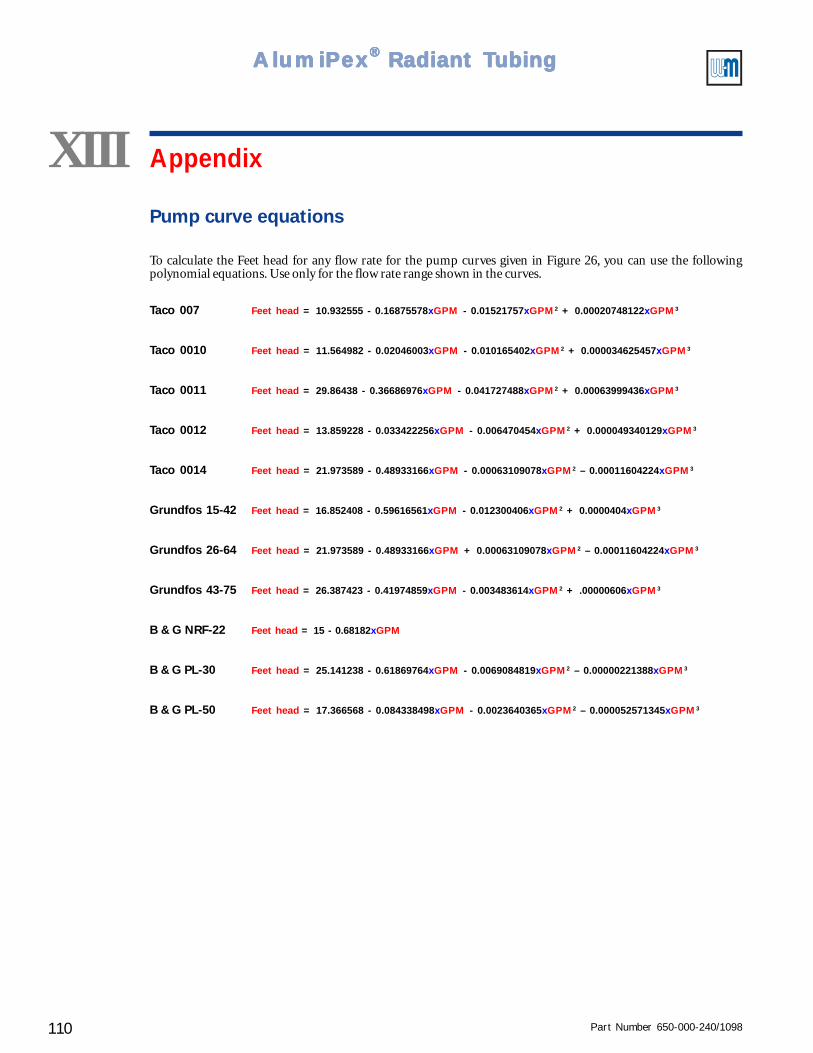
Part Number 650-000-240/1098110
AlumiPAlumiPAlumiPAlumiPAlumiPeeeeexxxxx® ® ® ® ® Radiant TRadiant TRadiant TRadiant TRadiant Tubingubingubingubingubing
Pump curve equations
To calculate the Feet head for any flow rate for the pump curves given in Figure 26, you can use the followingpolynomial equations. Use only for the flow rate range shown in the curves.
Taco 007 Feet head = 10.932555 - 0.16875578xGPM - 0.01521757xGPM2 + 0.00020748122xGPM3
Taco 0010 Feet head = 11.564982 - 0.02046003xGPM - 0.010165402xGPM2 + 0.000034625457xGPM3
Taco 0011 Feet head = 29.86438 - 0.36686976xGPM - 0.041727488xGPM2 + 0.00063999436xGPM3
Taco 0012 Feet head = 13.859228 - 0.033422256xGPM - 0.006470454xGPM2 + 0.000049340129xGPM3
Taco 0014 Feet head = 21.973589 - 0.48933166xGPM - 0.00063109078xGPM2 – 0.00011604224xGPM3
Grundfos 15-42 Feet head = 16.852408 - 0.59616561xGPM - 0.012300406xGPM2 + 0.0000404xGPM3
Grundfos 26-64 Feet head = 21.973589 - 0.48933166xGPM + 0.00063109078xGPM2 – 0.00011604224xGPM3
Grundfos 43-75 Feet head = 26.387423 - 0.41974859xGPM - 0.003483614xGPM2 + .00000606xGPM3
B & G NRF-22 Feet head = 15 - 0.68182xGPM
B & G PL-30 Feet head = 25.141238 - 0.61869764xGPM - 0.0069084819xGPM2 – 0.00000221388xGPM3
B & G PL-50 Feet head = 17.366568 - 0.084338498xGPM - 0.0023640365xGPM2 – 0.000052571345xGPM3
XIII Appendix
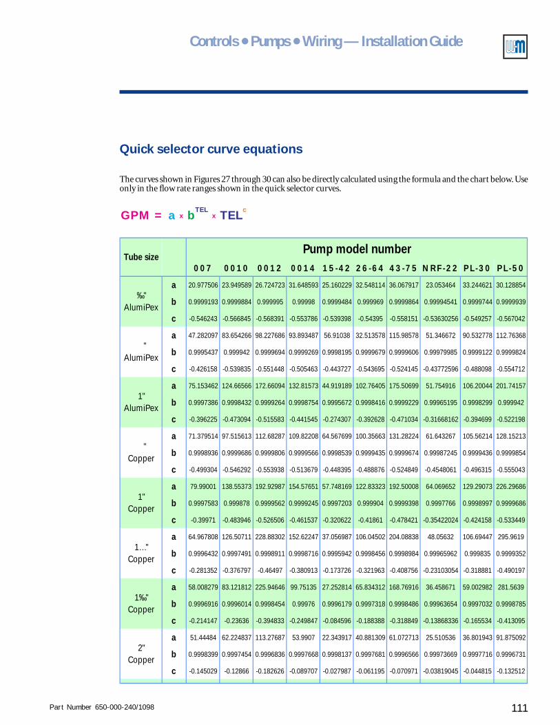
Part Number 650-000-240/1098 111
Controls ● Pumps ● Wiring — Installation Guide
Quick selector curve equations
The curves shown in Figures 27 through 30 can also be directly calculated using the formula and the chart below. Useonly in the flow rate ranges shown in the quick selector curves.
GPM = x xa bTEL
TELc
007 0010 0012 0014 15-42 26-64 43-75 NRF-22 PL-30 PL-50
a 20.977506 23.949589 26.724723 31.648593 25.160229 32.548114 36.067917 23.053464 33.244621 30.128854
b 0.9999193 0.9999884 0.999995 0.99998 0.9999484 0.999969 0.9999864 0.99994541 0.9999744 0.9999939
c -0.546243 -0.566845 -0.568391 -0.553786 -0.539398 -0.54395 -0.558151 -0.53630256 -0.549257 -0.567042
a 47.282097 83.654266 98.227686 93.893487 56.91038 32.513578 115.98578 51.346672 90.532778 112.76368
b 0.9995437 0.999942 0.9999694 0.9999269 0.9998195 0.9999679 0.9999606 0.99979985 0.9999122 0.9999824
c -0.426158 -0.539835 -0.551448 -0.505463 -0.443727 -0.543695 -0.524145 -0.43772596 -0.488098 -0.554712
a 75.153462 124.66566 172.66094 132.81573 44.919189 102.76405 175.50699 51.754916 106.20044 201.74157
b 0.9997386 0.9998432 0.9999264 0.9998754 0.9995672 0.9998416 0.9999229 0.99965195 0.9998299 0.999942
c -0.396225 -0.473094 -0.515583 -0.441545 -0.274307 -0.392628 -0.471034 -0.31668162 -0.394699 -0.522198
a 71.379514 97.515613 112.68287 109.82208 64.567699 100.35663 131.28224 61.643267 105.56214 128.15213
b 0.9998936 0.9999686 0.9999806 0.9999566 0.9998539 0.9999435 0.9999674 0.99987245 0.9999436 0.9999854
c -0.499304 -0.546292 -0.553938 -0.513679 -0.448395 -0.488876 -0.524849 -0.4548061 -0.496315 -0.555043
a 79.99001 138.55373 192.92987 154.57651 57.748169 122.83323 192.50008 64.069652 129.29073 226.29686
b 0.9997583 0.999878 0.9999562 0.9999245 0.9997203 0.999904 0.9999398 0.9997766 0.9998997 0.9999686
c -0.39971 -0.483946 -0.526506 -0.461537 -0.320622 -0.41861 -0.478421 -0.35422024 -0.424158 -0.533449
a 64.967808 126.50711 228.88302 152.62247 37.056987 106.04502 204.08838 48.05632 106.69447 295.9619
b 0.9996432 0.9997491 0.9998911 0.9998716 0.9995942 0.9998456 0.9998984 0.99965962 0.999835 0.9999352
c -0.281352 -0.376797 -0.46497 -0.380913 -0.173726 -0.321963 -0.408756 -0.23103054 -0.318881 -0.490197
a 58.008279 83.121812 225.94646 99.75135 27.252814 65.834312 168.76916 36.458671 59.002982 281.5639
b 0.9996916 0.9996014 0.9998454 0.99976 0.9996179 0.9997318 0.9998486 0.99963654 0.9997032 0.9998785
c -0.214147 -0.23636 -0.394833 -0.249847 -0.084596 -0.188388 -0.318849 -0.13868336 -0.165534 -0.413095
a 51.44484 62.224837 113.27687 53.9907 22.343917 40.881309 61.072713 25.510536 36.801943 91.875092
b 0.9998399 0.9997454 0.9996836 0.9997668 0.9998137 0.9997681 0.9996566 0.99973669 0.9997716 0.9996731
c -0.145029 -0.12866 -0.182626 -0.089707 -0.027987 -0.061195 -0.070971 -0.03819045 -0.044815 -0.132512
"AlumiPex
‰"AlumiPex
1"AlumiPex
Pump model number
1‰"Copper
2"Copper
Tube size
"Copper
1"Copper
1…"Copper

Part Number 650-000-240/1098112
Price $20