wiring duct c-68–c-77 wiring trough -...
TRANSCRIPT
Wiring Duct & Wiring Trough
In this section...
Wiring duct & Wiring trough
Ty-Duct® Wiring Duct .................................................... C-68–C-77
Wiring Duct Tools and Accessories ................................ C-78–C-81
Wiring Duct Technical Information ................................. C-82–C-86
Carlon® Wiring Trough and Accessories ......................... C-87–C-89
Wiring Trough Technical Information .............................. C-90–C-92

C-68www.tnb.com
United StatesTel: 901.252.8000 800.816.7809Fax: 901.252.1354
Technical ServicesTel: 888.862.3289
Ty-Duct ® Wiring Duct
Fast
enin
g Sy
stem
s —
Wiri
ng D
uct &
Wiri
ng T
roug
h
Thomas & Betts’ innovative new Ty-Duct products offer a total solution for routing and concealing wiring in control panels. Many different sizes are available to accommodate anything from the smallest wallmount panel to the larger integrated systems!
Here are some of the impressive features incorporated into our wiring duct solutions.
Ty-Duct® Features
Ty-Duct® — The versatile configurations you need for routing and concealing wiring!
Ty-Duct® Certifications
• UL® Recognized Continuous-Use Temperature — 122° F (50° C) for Standard PVC Material 203° F (95° C) for Halogen-Free Material
• UL® 94 Flammability — Rating of V-0 for Standard PVC Material Rating of V-1 for Halogen-Free Material
• Conforms with NFPA 79-2011 Section 13.3.1 Requirement for Flame-Retardant Material
• CE compliant for European shipping
• CSA Certified
• RoHS Certified
• Available in Wide and Narrow Slot versions to meet your capacity and flexibility needs
• Widths from .75" to 6" and depths from 1" to 5"
• Complete selection of accessories and tools for installation
• Lead-free construction
• Lightweight halogen-free material available for Wide Slot Wiring Duct
Available in 2 Colors
Gray White

United StatesTel: 901.252.8000 800.816.7809Fax: 901.252.1354
Technical ServicesTel: 888.862.3289www.tnb.com
C-69
Fastening Systems —
Wiring Duct & W
iring Trough
Ty-Duct ® Wiring Duct
Two-point contact design enables easy cover installation
Flush cover design provides greater capacity
Co-extruded cover won’t slip off once installed
Dual score lines — top allows fingers to be removed
without tools, and bottom allows easy removal for
smooth transitions
Universal mounting clip enables divider to be
snapped into place and provides slots for cable ties
Embossed holes on 1⁄2" and wider sizes allow the installation of universal mounting clips even
after duct has been riveted to the panel
V-shaped slot lead-ins funnel wires for easier insertion
Writable protective film prevents scuffs to reduce
scrap and cleaning
Solid divider separates low-voltage common cabling from
electrical wiring
Triple-restricted slots speed installation and retain
wire in duct
Smooth corners and edges won’t damage wires
Grooved cover provides better grip for removal and reinstalling

www.tnb.comUnited StatesTel: 901.252.8000 800.816.7809Fax: 901.252.1354
Technical ServicesTel: 888.862.3289
C-70
Ty-Duct ® Wiring Duct
Fast
enin
g Sy
stem
s —
Wiri
ng D
uct &
Wiri
ng T
roug
h Ordering the Ty-Duct® products you need is easy!Select the appropriate Ty-Duct® solutions for your application.
[ _ ] = space for color identifier:
G = Gray
W = White
For Ty-Duct® Wiring Duct:
Cat. No. DesCriptioNsize (W X H)
iN. mmCover
Cat. No.DuCt stD. CtN. Qty.
Cover stD. CtN. Qty.
LeNGtH (ft.)
ty75X1Wp[ G ]6Nm .75 x 1 Wide Slot Duct .94 x 1.09 23.9 x 27.7 120ty75X15Wp[W ]6 .75 x 1.5 Wide Slot Duct .94 x 1.56 23.9 x 39.6 ty75Cp[ _ ]6 120 120 6ty75X2Wp[ W ]6 .75 x 2 Wide Slot Duct .94 x 2.07 23.9 x 52.6 120
To order duct without mounting holes, add suffix NM to catalog number. Example: TY75X1WPG6NM is a .75" x 1" wide slot gray duct with no mounting holes.
Nominal Width x Nominal Height Standard Carton Quantity
Standard lengths are 6 feet.Catalog Number must be completed by adding suffix G for Gray, W for White. Example: TY75x2WPW6 is a .75" x 2" wide slot white duct. Cover color must be specified also.
WP = Wide SlotNP = Narrow Slot
1
2
For Ty-Duct® Covers:
examples
TY ___ x ___ __ _ 6 __
Width Height style Color Length special
TY CP 6
Width Color Length
Note: See product expiration date on packages with adhesive. Periodically check product for adhesion and replace as needed. Product is for wire management only and is not intended for use as a primary support of wire, cable, etc.

United StatesTel: 901.252.8000 800.816.7809Fax: 901.252.1354
Technical ServicesTel: 888.862.3289www.tnb.com
C-71
Fastening Systems —
Wiring Duct & W
iring Trough
Ty-Duct ® Wiring Duct
Note: See product expiration date on packages with adhesive. Periodically check product for adhesion and replace as needed. Product is for wire management only and is not intended for use as a primary support of wire, cable, etc.
For Ty-Duct® Dividers:
Cat. No. DesCriptioNLeNGtH
(ft.)stD.
CtN. Qty
ty2D[ sp ][ G ]6 2" High Wall Divider 6 120
Catalog Number must be completed by adding suffix G for Gray, W for White.
Catalog Number must be completed by adding suffix SP for Solid or WP for Wide Slot. Example: TY2DSPG6 is a 2" high solid wall gray divider.
Order Ty-Duct® Accessories

www.tnb.comUnited StatesTel: 901.252.8000 800.816.7809Fax: 901.252.1354
Technical ServicesTel: 888.862.3289
C-72
Ty-Duct ® Wiring Duct
Fast
enin
g Sy
stem
s —
Wiri
ng D
uct &
Wiri
ng T
roug
h Greater sidewall rigidity with increased versatility!
Wide Slot Wiring Duct — PVC• Wide fingers and slots increase rigidity
and enable insertion of bundles
• Non-slip cover does not slide easily and resists vibration
• Rounded edges keep hands and wires free of abrasion
• V-shaped slot lead-in enables easier and faster wire installation
• Dual score lines are designed to yield clean breakoffs at the base of the slot and the duct
• Restricted slot design makes sure that wires are held with or without the cover inserted
• Cover attaches flush with sidewall for finished look and increased wire capacity
• Versatile North American and DIN Standard mounting holes enables same duct for multiple applications
• Constructed of flame-retardant PVC
• Lead-free construction
Embossed Holes
Wide Fingers & Slots
V-Shaped Slot Lead-In
Grooved Cover
Two-Point Contact Design
Flush Cover Design
Dual Score Lines
United StatesTel: 901.252.8000 800.816.7809Fax: 901.252.1354
Technical ServicesTel: 888.862.3289www.tnb.com
C-73
Fastening Systems —
Wiring Duct & W
iring Trough
Ty-Duct ® Wiring Duct
Cat. No.* DesCriptioN
size (W x H) Cover Cat. No.*
DuCt stD.CtN. Qty.
Cover stD. CtN. Qty.
leNgtH (ft.)iN. mm
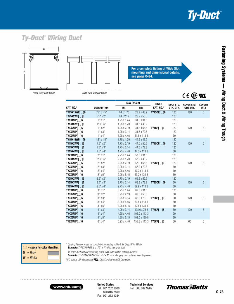
ty75x15Wp[ _ ]6 .75" x 1.5" .94 x 1.70 23.9 x 43.2 ty75Cp[ _ ]6 120 120 6ty75x2Wp[ _ ]6 .75" x 2" .94 x 2.19 23.9 x 55.6 120ty1x1Wp[ _ ]6 1" x 1" 1.25 x 1.24 31.8 x 31.5 120ty1x15Wp[ _ ]6 1" x 1.5" 1.25 x 1.70 31.8 x 43.2 120ty1x2Wp[ _ ]6 1" x 2" 1.25 x 2.19 31.8 x 55.6 ty1Cp[ _ ]6 120 120 6ty1x3Wp[ _ ]6 1" x 3" 1.25 x 3.14 31.8 x 79.8 120ty1x4Wp[ _ ]6 1" x 4" 1.25 x 4.46 31.8 x 113.3 60ty15x15Wp[ _ ]6 1.5" x 1.5" 1.75 x 1.70 44.5 x 43.2 120ty15x2Wp[ _ ]6 1.5" x 2" 1.75 x 2.19 44.5 x 55.6 ty15Cp[ _ ]6 120 120 6ty15x3Wp[ _ ]6 1.5" x 3" 1.75 x 3.14 44.5 x 79.8 120ty15x4Wp[ _ ]6 1.5" x 4" 1.75 x 4.46 44.5 x 113.3 60ty2x1Wp[ _ ]6 2" x 1" 2.25 x 1.24 57.2 x 31.5 120ty2x15Wp[ _ ]6 2" x 1.5" 2.25 x 1.70 57.2 x 43.2 120ty2x2Wp[ _ ]6 2" x 2" 2.25 x 2.19 57.2 x 55.6 ty2Cp[ _ ]6 120 120 6ty2x3Wp[ _ ]6 2" x 3" 2.25 x 3.14 57.2 x 79.8 60ty2x4Wp[ _ ]6 2" x 4" 2.25 x 4.46 57.2 x 113.3 60ty2x5Wp[ _ ]6 2" x 5" 2.25 x 5.15 57.2 x 130.8 60ty25x2Wp[ _ ]6 2.5" x 2" 2.75 x 2.19 69.9 x 55.6 120ty25x3Wp[ _ ]6 2.5" x 3" 2.75 x 3.14 69.9 x 79.8 ty25Cp[ _ ]6 60 120 6ty25x4Wp[ _ ]6 2.5" x 4" 2.75 x 4.46 69.9 x 113.3 60ty3x1Wp[ _ ]6 3" x 1" 3.25 x 1.24 82.6 x 31.5 120ty3x2Wp[ _ ]6 3" x 2" 3.25 x 2.19 82.6 x 55.6 60ty3x3Wp[ _ ]6 3" x 3" 3.25 x 3.14 82.6 x 79.8 ty3Cp[ _ ]6 60 120 6ty3x4Wp[ _ ]6 3" x 4" 3.25 x 4.46 82.6 x 113.3 60ty3x5Wp[ _ ]6 3" x 5" 3.25 x 5.15 82.6 x 130.8 60ty4x3Wp[ _ ]6 4" x 3" 4.25 x 3.14 108.0 x 79.8 ty4Cp[ _ ]6 60 120 6ty4x4Wp[ _ ]6 4" x 4" 4.25 x 4.46 108.0 x 113.3 30ty4x5Wp[ _ ]6 4" x 5" 4.25 x 5.15 108.0 x 130.8 30ty6x4Wp[ _ ]6 6" x 4" 6.25 x 4.46 158.8 x 113.3 ty6Cp[ _ ]6 30 60 6
[ _ ] = space for color identifier:
g = Gray
W = White
* Catalog Number must be completed by adding suffix G for Gray, W for White. Example: TY75X1WPG6 is a .75" x 1" wide slot gray duct.
To order duct without mounting holes, add suffix NM to catalog number. Example: TY75X1WPG6NM is a .75" x 1" wide slot gray duct with no mounting holes.
PVC duct is UL® Recognized , CSA Certified and CE Compliant.
Front View with Cover
H
W
Side View without Cover
for a complete listing of Wide slot mounting and dimensional details, see page C-84.

www.tnb.comUnited StatesTel: 901.252.8000 800.816.7809Fax: 901.252.1354
Technical ServicesTel: 888.862.3289
C-74
Ty-Duct ® Wiring Duct
Fast
enin
g Sy
stem
s —
Wiri
ng D
uct &
Wiri
ng T
roug
h
Embossed Holes
V-Shaped Slot Lead-In
Grooved Cover
Restricted Slot Design
Three Levels of Wire Service
Narrow Fingers & Slots
Designed to fit the spacing of high-density terminal blocks!
Narrow Slot Wiring Duct
• Lead-free construction
• Constructed of flame-retardant PVC
Two Levels of Wire Service
Flush Cover Design
Dual Score Lines
Two-Point Contact Design
• Smaller, higher number of fingers for more concise harnessing
• Non-slip cover does not slide easily and resists vibration
• Rounded edges keep hands and wires free of abrasion
• V-shaped slot lead-in enables easier and faster wire installation
• Restricted slot design makes sure that wires are held with or without the cover inserted
• Cover attaches flush with sidewall for finished look and increased wire capacity
• Versatile North American and DIN Standard mounting holes enable same duct for multiple applications
• Dual score lines are designed to yield clean breakoffs at the base of the slot and the duct

United StatesTel: 901.252.8000 800.816.7809Fax: 901.252.1354
Technical ServicesTel: 888.862.3289www.tnb.com
C-75
Fastening Systems —
Wiring Duct & W
iring Trough
Ty-Duct ® Wiring Duct
Cat. No.* DesCriptioN
size (W X H)Cover
Cat. No.*DuCt stD.CtN. Qty.
Cover stD. CtN. Qty.
leNgtH (ft.)iN. mm
ty75X15Np[ _ ]6 .75" x 1.5" .94 x 1.70 23.9 x 43.2 ty75Cp[ _ ]6 120 120 6ty1X1Np[ _ ]6 1" x 1" 1.25 x 1.24 31.8 x 31.5 120ty1X15Np[ _ ]6 1" x 1.5" 1.25 x 1.70 31.8 x 43.2 120ty1X2Np[ _ ]6 1" x 2" 1.25 x 2.19 31.8 x 55.6 ty1Cp[ _ ]6 120 120 6ty1X3Np[ _ ]6 1" x 3" 1.25 x 3.14 31.8 x 79.8 120ty1X4Np[ _ ]6 1" x 4" 1.25 x 4.46 31.8 x 113.3 60ty15X1Np[ _ ]6 1.5" x 1" 1.75 x 1.24 44.5 x 31.5 120ty15X15Np[ _ ]6 1.5" x 1.5" 1.75 x 1.70 44.5 x 43.2 120ty15X2Np[ _ ]6 1.5" x 2" 1.75 x 2.19 44.5 x 55.6 ty15Cp[ _ ]6 120 120 6ty15X3Np[ _ ]6 1.5" x 3" 1.75 x 3.14 44.5 x 79.8 120ty15X4Np[ _ ]6 1.5" x 4" 1.75 x 4.46 44.5 x 113.3 60ty2X1Np[ _ ]6 2" x 1" 2.25 x 1.24 57.2 x 31.5 120ty2X15Np[ _ ]6 2" x 1.5" 2.25 x 1.70 57.2 x 43.2 120ty2X2Np[ _ ]6 2" x 2" 2.25 x 2.19 57.2 x 55.6 ty2Cp[ _ ]6 120 120 6ty2X3Np[ _ ]6 2" x 3" 2.25 x 3.14 57.2 x 79.8 60ty2X4Np[ _ ]6 2" x 4" 2.25 x 4.46 57.2 x 113.3 60ty2X5Np[ _ ]6 2" x 5" 2.25 x 5.15 57.2 x 130.8 60ty25X2Np[ _ ]6 2.5" x 2" 2.75 x 2.19 69.9 x 55.6 120ty25X3Np[ _ ]6 2.5" x 3" 2.75 x 3.14 69.9 x 79.8 ty25Cp[ _ ]6 60 120 6ty25X4Np[ _ ]6 2.5" x 4" 2.75 x 4.46 69.9 x 113.3 60ty3X1Np[ _ ]6 3" x 1" 3.25 x 1.24 82.6 x 31.5 120ty3X2Np[ _ ]6 3" x 2" 3.25 x 2.19 82.6 x 55.6 60ty3X3Np[ _ ]6 3" x 3" 3.25 x 3.14 82.6 x 79.8 ty3Cp[ _ ]6 60 120 6ty3X4Np[ _ ]6 3" x 4" 3.25 x 4.46 82.6 x 113.3 60ty3X5Np[ _ ]6 3" x 5" 3.25 x 5.15 82.6 x 130.8 60ty4X2Np[ _ ]6 4" x 2" 4.25 x 2.19 108.0 x 55.6 60ty4X3Np[ _ ]6 4" x 3" 4.25 x 3.14 108.0 x 79.8 ty4Cp[ _ ]6 60 120 6ty4X4Np[ _ ]6 4" x 4" 4.25 x 4.46 108.0 x 113.3 30ty4X5Np[ _ ]6 4" x 5" 4.25 x 5.15 108.0 x 130.8 30
* Catalog Number must be completed by adding suffix G for Gray, W for White. Example: TY75X15NPB6 is a .75" x 1.5" narrow slot black duct.
To order duct without mounting holes, add suffix NM to catalog number. Example: TY75X15NPB6NM is a .75" x 1.5" narrow slot black duct with no mounting holes.
PVC duct is UL Recognized , CSA Certified and CE Compliant.
Front View with Cover
H
W
Side View without Cover
[ _ ] = space for color identifier:
g = Gray
W = White
for a complete listing of Narrow slot mounting and dimensional details, see page C-85.

www.tnb.comUnited StatesTel: 901.252.8000 800.816.7809Fax: 901.252.1354
Technical ServicesTel: 888.862.3289
C-76
Ty-Duct ® Wiring Duct
Fast
enin
g Sy
stem
s —
Wiri
ng D
uct &
Wiri
ng T
roug
h
Embossed Holes
V-Shaped Slot Lead-In
Grooved Cover
Wide Fingers & Slots
• Halogen-free construction — RoHS Compliant
• Higher temperature rating than standard PVC material (203° F/95° C)
• UL94V-1 flammability rating
• Wide fingers and slots increase rigidity and enable for insertion of bundles
• Non-slip cover does not slide easily and resists vibration
• Dual score lines are designed to yield clean breakoffs at the base of the slot and the duct
• V-shaped slot lead-in enables easier and faster wire installation
Flush Cover Design
Dual Score Lines
Two-Point Contact Design
Perfect for passenger or crew areas where smoke toxicity is a concern!
Halogen-Free Wide Slot Wiring Duct
• Light weight
• Typical applications include rail/mass transit/subway cars, shops and offshore oil and gas platforms

United StatesTel: 901.252.8000 800.816.7809Fax: 901.252.1354
Technical ServicesTel: 888.862.3289www.tnb.com
C-77
Fastening Systems —
Wiring Duct & W
iring Trough
Ty-Duct ® Wiring Duct
Cat. No. DesCriptioN
size (W x H) Cover Cat. No.
DuCt stD.CtN. Qty.
Cover stD. CtN. Qty.
leNgtH (ft.)iN. mm
ty1x1WHW6 1" x 1" 1.25 x 1.24 31.8 x 31.5 120ty1x15WHW6 1" x 1.5" 1.25 x 1.70 31.8 x 43.2 120ty1x2WHW6 1" x 2" 1.25 x 2.19 31.8 x 55.6 ty1CHW6 120 120 6ty1x3WHW6 1" x 3" 1.25 x 3.14 31.8 x 79.8 120ty1x4WHW6 1" x 4" 1.25 x 4.46 31.8 x 113.3 60ty15x15WHW6 1.5" x 1.5" 1.75 x 1.70 44.5 x 43.2 120ty15x2WHW6 1.5" x 2" 1.75 x 2.19 44.5 x 55.6 ty15CHW6 120 120 6ty15x3WHW6 1.5" x 3" 1.75 x 3.14 44.5 x 79.8 120ty15x4WHW6 1.5" x 4" 1.75 x 4.46 44.5 x 113.3 60ty2x1WHW6 2" x 1" 2.25 x 1.24 57.2 x 31.5 120ty2x2WHW6 2" x 2" 2.25 x 2.19 57.2 x 55.6 ty2CHW6 120 120 6ty2x3WHW6 2" x 3" 2.25 x 3.14 57.2 x 79.8 60ty2x4WHW6 2" x 4" 2.25 x 4.46 57.2 x 113.3 60ty3x1WHW6 3" x 1" 3.25 x 1.24 82.6 x 31.5 120ty3x2WHW6 3" x 2" 3.25 x 2.19 82.6 x 55.6 60ty3x3WHW6 3" x 3" 3.25 x 3.14 82.6 x 79.8 ty3CHW6 60 120 6ty3x4WHW6 3" x 4" 3.25 x 4.46 82.6 x 113.3 60ty3x5WHW6 3" x 5" 3.25 x 5.15 82.6 x 130.8 60ty4x2WHW6 4" x 2" 4.25 x 2.19 108.0 x 55.6 60ty4x3WHW6 4" x 3" 4.25 x 3.14 108.0 x 79.8 ty4CHW6 60 120 6ty4x4WHW6 4" x 4" 4.25 x 4.46 108.0 x 113.3 30ty4x5WHW6 4" x 5" 4.25 x 5.15 108.0 x 130.8 30
Front View with Cover
H
W
Side View without Cover
Cat. No.fits DuCt
traDe sizestD. CtN.
Qty.leNgtH
(ft.)
ty1DsHW6 1" H 120 6ty1.5DsHW6 11⁄2" H 120 6ty2DsHW6 2" H 120 6ty3DsHW6 3" H 1120 6ty4DsHW6 4" H 120 6ty5DsHW6 5" H 120 6
To order duct without mounting holes, add suffix NM to catalog number. Example: TY1XWHW6NM is a 1" x 1" wide slot halogen-free white duct with no mounting holes.
Halogen-free (modified PPE) duct is UL® Recognized , CSA Certified and meets the JIC requirements.
W = White
Halogen-Free Wiring Duct Solid Divider Wall
for a complete listing of solid Wall mounting and dimensional details, see page C-84.
www.tnb.comUnited StatesTel: 901.252.8000 800.816.7809Fax: 901.252.1354
Technical ServicesTel: 888.862.3289
C-78
Wiring Duct Tools and Accessories
Fast
enin
g Sy
stem
s —
Wiri
ng D
uct &
Wiri
ng T
roug
h
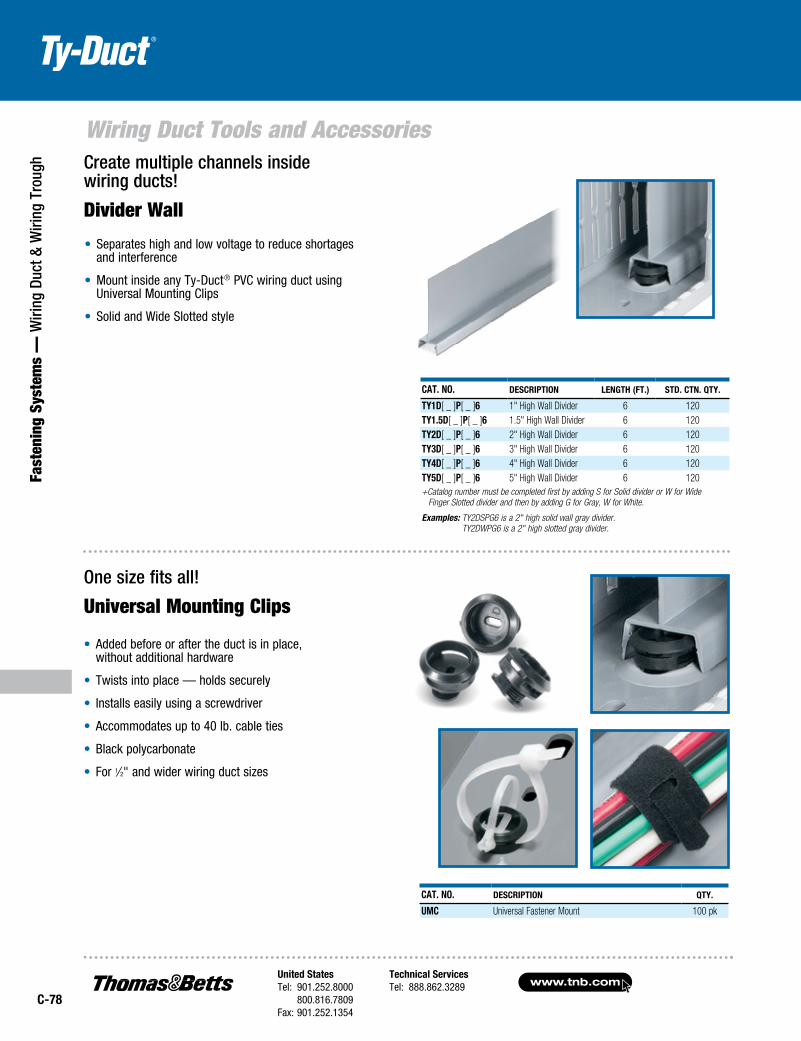
• Added before or after the duct is in place, without additional hardware
• Twists into place — holds securely
• Installs easily using a screwdriver
• Accommodates up to 40 lb. cable ties
• Black polycarbonate
• For 1⁄2" and wider wiring duct sizes
Cat. No. DesCriptioN leNgth (ft.) stD. CtN. Qty.
ty1D[ _ ]p[ _ ]6 1" High Wall Divider 6 120ty1.5D[ _ ]p[ _ ]6 1.5" High Wall Divider 6 120ty2D[ _ ]p[ _ ]6 2" High Wall Divider 6 120ty3D[ _ ]p[ _ ]6 3" High Wall Divider 6 120ty4D[ _ ]p[ _ ]6 4" High Wall Divider 6 120ty5D[ _ ]p[ _ ]6 5" High Wall Divider 6 120+Catalog number must be completed first by adding S for Solid divider or W for Wide
Finger Slotted divider and then by adding G for Gray, W for White.
Examples: TY2DSPG6 is a 2" high solid wall gray divider. TY2DWPG6 is a 2" high slotted gray divider.
Cat. No. DesCriptioN Qty.
UMC Universal Fastener Mount 100 pk
Create multiple channels inside wiring ducts!
Divider Wall
• Separates high and low voltage to reduce shortages and interference
• Mount inside any Ty‑Duct® PVC wiring duct using Universal Mounting Clips
• Solid and Wide Slotted style
One size fits all!
Universal Mounting Clips

United StatesTel: 901.252.8000 800.816.7809Fax: 901.252.1354
Technical ServicesTel: 888.862.3289www.tnb.com
C-79
Fastening Systems —
Wiring Duct & W
iring Trough
Wiring Duct Tools and Accessories
stD. Cat. No. DesCriptioN Qty.
08200C 3⁄16" Plastic Rivet 100 pk08200M 3⁄16" Plastic Rivet 1,000 pk
Cat. No. WiDth (iN.) stD. CtN. Qty.
ty1MC 1 100ty15MC 1.5 100ty2MC 2 100ty3MC 3 100All are .75"D x .35"H and made of Type 316 stainless steel.
Plastic rivets make mounting ducts easy!Plastic Rivets
• Fast installation
• Durable and economical
• Used with panel thickness from .030"–.125" thick
• Recommended Panel Hole size: .196" ± .02
Ideal for high-temperature environments!Mounting Clips• Speeds duct mounting
• Enables duct removal
• Provides a stand‑off between panel and duct to prevent direct heat transfer — ideal for high‑temperature environments
NEW!NEW!
Minimum mounting rivet distance for ducts less than 11⁄2" wide.
12"
Minimum mounting rivet distance for ducts 11⁄2" to 21⁄2" wide.
6"
Minimum mounting rivet distance for ducts greater than 21⁄2" wide. Installed top and bottom.
6"

www.tnb.comUnited StatesTel: 901.252.8000 800.816.7809Fax: 901.252.1354
Technical ServicesTel: 888.862.3289
C-80
Wiring Duct Tools and Accessories
Fast
enin
g Sy
stem
s —
Wiri
ng D
uct &
Wiri
ng T
roug
h
Features include:• Duct Cutting Tools for a clean professional finish
• Finger Cutting Tools that make modifications simple
• Notching Tools for duct sidewalls to facilitate tee and corner junctions
• Benchmount Cutting Tools for fast, high volume duct cutting
• Rivet Installation Tools for quick duct mounting
The wiring duct tools you need for every application!
Lightweight and durable!Duct/ Cover Cutting Tool
Cat. No. DesCriptioN
CC125 Handheld Duct CuttersX-25tB Handheld Duct Cutter — Long
• All-steel construction
• Sharp cutting surface
• Replaceable blades available
Cut duct fingers easily!Finger Cutting Tool
• Rugged die-cast construction with insulated handles for a comfortable, non-slip grip
• Removes duct fingers in tight places
• Works with all slotted wiring duct
• Also cuts round and solid wall duct
• Spring loaded
Cat. No. DesCriptioN
DK-65tB Duct Finger Cutter
Improved Performance!
Improved Performance!

United StatesTel: 901.252.8000 800.816.7809Fax: 901.252.1354
Technical ServicesTel: 888.862.3289www.tnb.com
C-81
Fastening Systems —
Wiring Duct & W
iring Trough
Wiring Duct Tools and AccessoriesFor fast, high-volume duct cutting!Benchmount Cutting Tool• Engineered for use with Ty-Duct®
plastic wiring ducts and covers
• All-steel construction lasts for years
• Adjustable gauge sets the desired length of duct
• Easy-to-read measuring indicator
• Adjustable stop for easy repeated cutting
• Sharp, easy-to-replace blades
Cat. No. DesCriptioN
DC-125tB Benchmount Duct Cutter
Notch duct sidewalls fast!Notching Tool
• Notches sidewalls to bottom scoreline
• Facilitates tee and corner junctions
• Rugged design
• Easy to use
• Spring loaded
Cat. No. DesCriptioN
DNt-100tB Duct Notching Tool
Mount ducts quickly!Rivet Installation Tool• Use for setting duct rivets
• Pressure on the tool head secures the rivet in place
Cat. No. DesCriptioN
08205 08200 Series Rivet Installation Tool
plastic rivets(see page C-79)
You may also need…

www.tnb.comUnited StatesTel: 901.252.8000 800.816.7809Fax: 901.252.1354
Technical ServicesTel: 888.862.3289
C-82
Wiring Duct Technical Information
Fast
enin
g Sy
stem
s —
Wiri
ng D
uct &
Wiri
ng T
roug
h Wiring Duct — Wire Fill CapacityNote: Wire fill is based on 50% fill of duct area.
AreA (InChes2)
eleCtrICAl DAtA CAble
normAl DuCt sIze
8 AWG 10 AWG 12 AWG 14 AWG 16 AWG 18 AWG 22 AWG 24 AWG
0.216 0.153 0.122 0.158 0.105 0.139 0.165 0.096 0.125 0.084 0.113 0.065 0.217 0.250 0.422
(In.)
thhn thhn thhn mtW thhn mtW mtW thhn mtW thhn mtW mtWutp/Cm CAt5e
utp/Cm CAt6 utp/CmW h
.75 X 1.00 .750 5 9 14 9 19 11 8 23 14 30 17 51 5 3 1
.75 X 1.50 1.125 7 14 22 13 29 17 12 35 21 46 25 76 7 5 2
.75 X 2.00 1.500 9 18 29 17 39 22 16 47 27 61 34 101 9 7 21.00 X 1.00 1.000 6 12 19 11 26 15 10 31 18 40 22 68 6 5 21.00 X 1.50 1.500 9 18 29 17 39 22 16 47 27 61 34 101 9 7 21.00 X 2.00 2.000 12 24 38 23 52 30 21 62 37 81 45 135 12 9 31.00 X 3.00 3.000 18 37 58 34 78 44 31 93 55 121 67 203 18 14 51.00 X 4.00 4.000 24 49 77 46 104 59 42 124 73 162 90 270 24 18 61.50 X 1.00 1.500 9 18 29 17 39 22 16 47 27 61 34 101 9 7 21.50 X 1.50 2.250 14 27 43 26 58 33 24 70 41 91 50 152 14 10 41.50 X 2.00 3.000 18 37 58 34 78 44 31 93 55 121 67 203 18 14 51.50 X 3.00 4.500 27 55 86 52 117 67 47 140 82 182 101 304 27 21 71.50 X 4.00 6.000 36 73 115 69 155 89 63 186 110 243 134 406 36 27 102.00 X 1.00 2.000 12 24 38 23 52 30 21 62 37 81 45 135 12 9 32.00 X 1.50 3.000 18 37 58 34 78 44 31 93 55 121 67 203 18 14 52.00 X 2.00 4.000 24 49 77 46 104 59 42 124 73 162 90 270 24 18 62.00 X 3.00 6.000 36 73 115 69 155 89 63 186 110 243 134 406 36 27 102.00 X 4.00 8.000 48 98 154 92 207 118 84 248 146 324 179 541 49 37 132.00 X 5.00 10.000 60 122 192 114 259 148 105 310 183 405 224 676 61 46 162.50 X 2.00 5.000 30 61 96 57 130 74 52 155 91 202 112 338 30 23 82.50 X 3.00 7.500 45 92 144 86 194 111 79 233 137 304 168 507 46 34 122.50 X 4.00 10.000 60 122 192 114 259 148 105 310 183 405 224 676 61 46 163.00 X 1.00 3.000 18 37 58 34 78 44 31 93 55 121 67 203 18 14 53.00 X 2.00 6.000 36 73 115 69 155 89 63 186 110 243 134 406 36 27 103.00 X 3.00 9.000 54 110 173 103 233 133 94 279 165 364 201 609 55 41 143.00 X 4.00 12.000 72 146 230 137 311 177 126 372 219 486 269 811 73 55 193.00 X 5.00 15.000 90 183 288 172 389 222 157 465 274 607 336 1014 91 69 244.00 X 1.50 6.000 36 73 115 69 155 89 63 186 110 243 134 406 36 27 104.00 X 2.00 8.000 48 98 154 92 207 118 84 248 146 324 179 541 49 37 134.00 X 3.00 12.000 72 146 230 137 311 177 126 372 219 486 269 811 73 55 194.00 X 4.00 16.000 96 195 307 183 415 237 168 496 293 648 358 1082 97 73 264.00 X 5.00 20.000 120 244 384 229 518 296 210 620 366 810 448 1352 121 91 326.00 X 4.00 24.000 144 293 461 275 622 355 252 744 439 972 537 1623 146 110 39
Number of wires = Duct W x H 2 1.75 x (Wire O.D.) 2
Formula for Calculating Fill Capacity

United StatesTel: 901.252.8000 800.816.7809Fax: 901.252.1354
Technical ServicesTel: 888.862.3289www.tnb.com
C-83
Fastening Systems —
Wiring Duct & W
iring Trough
Wiring Duct Technical Information
property unIts Astm test pVC hAloGen Free
Specific Gravity D792 1.43 1.10IZOD ft.-lb./in. D256 2 5.0Flexural Strength psi D790 10,900 12,800Flexural Modulus psi D790 382,000 360,000Tensile Strength psi D638 5,500 7,800Compressive Strength psi D695 8,600 16,000Water Absorption 24 hrs.–% D570 .10 .07Hardness Rockwell
Duro DD785D676
R-11178
R-115
Dielectric Strength 60Hz, 25° C, s/t
D149vpm 400
Dielectric Constant 60Hz, Dry 1MHz, Dry
D1501.9 2.65
2.64Volume Resistivity ohm-cm D257 1017Heat Deflecting (° F@ 264 psi) ° F D648 158 212Flammability 94 V-O 94 V-1The above information is believed reliable. The user should, however, check the applicable specifications to verify values.
Rigid Polyvinyl Chloride (PVC)
• General-purpose material for indoor applications
• UL94 flammability rating of V-0
• UL® Recognized for use in temperatures up to 50° C (122° F)
• Economical wiring duct material
Halogen Free
• For use in halogen-free or high-temperature applications
• UL94 flammability rating of V-1
• UL® Recognized for use in higher temperatures up to 95° C (203° F)
• 20% lighter than PVC
Properties of Materials Used in Wiring Duct

www.tnb.comUnited StatesTel: 901.252.8000 800.816.7809Fax: 901.252.1354
Technical ServicesTel: 888.862.3289
C-84
Wiring Duct Technical Information
Fast
enin
g Sy
stem
s —
Wiri
ng D
uct &
Wiri
ng T
roug
h
TRADE SIZE DIMENSIONS (INChES)
W h A B C D E F G
.75 X 1.00 .94 1.24 .94 1.03 .30 .10 .80
.75 X 1.50 .94 1.70 .94 1.50 .30 .10 .80
.75 X 2.00 .94 2.19 .94 2.01 .30 .10 .801.00 X 1.00 1.25 1.24 1.25 1.03 .30 .10 .801.00 X 1.50 1.25 1.70 1.25 1.50 .30 .10 .801.00 X 2.00 1.25 2.19 1.25 2.01 .30 .10 .801.00 X 3.00 1.25 3.14 1.25 2.99 .30 .10 1.001.00 X 4.00 1.25 4.46 1.25 4.32 .30 .10 1.001.50 X 1.00 1.75 1.24 1.75 1.03 .30 .10 .801.50 X 1.50 1.75 1.70 1.75 1.50 .30 .10 .801.50 X 2.00 1.75 2.19 1.75 2.01 .30 .10 .801.50 X 3.00 1.75 3.14 1.75 2.99 .30 .10 1.001.50 X 4.00 1.75 4.46 1.75 4.32 .30 .10 1.002.00 X 1.00 2.25 1.24 2.25 1.05 .30 .10 .802.00 X 1.50 2.25 1.70 2.25 1.52 .30 .10 .802.00 X 2.00 2.25 2.19 2.25 2.03 .30 .10 .802.00 X 3.00 2.25 3.14 2.25 3.00 .30 .10 1.002.00 X 4.00 2.25 4.46 2.25 4.33 .30 .10 1.002.00 X 5.00 2.25 5.15 2.25 5.02 .38 .10 1.332.50 X 2.00 2.75 2.19 2.75 2.03 .30 .10 .802.50 X 3.00 2.75 3.14 2.75 3.00 .30 .10 1.002.50 X 4.00 2.75 4.46 2.75 4.33 .30 .10 1.003.00 X 1.00 3.25 1.24 3.25 1.06 .30 .10 .803.00 X 2.00 3.25 2.19 3.25 2.08 .30 .10 .803.00 X 3.00 3.25 3.14 3.25 3.06 .30 .10 1.003.00 X 4.00 3.25 4.46 3.25 4.39 .30 .10 1.003.00 X 5.00 3.25 5.15 3.25 5.06 .38 .10 1.334.00 X 1.50 4.25 1.70 4.25 1.58 .30 .10 .804.00 X 2.00 4.25 2.19 4.25 2.08 .30 .10 .804.00 X 3.00 4.25 3.14 4.25 3.06 .30 .10 1.004.00 X 4.00 4.25 4.46 4.25 4.39 .30 .10 1.004.00 X 5.00 4.25 5.15 4.25 5.06 .38 .10 1.336.00 X 4.00 6.25 4.46 6.25 4.39 .30 .10 1.00
Dimensions shown are for reference only. Contact T&B for specific dimensional needs.
Ty-Duct ® Wide Slot Wiring Duct Dimensions
EF
Side View without CoverFront View with Cover
D
G
B
C
A Pattern for 3⁄4" & 1"
1.00"
0.315" x 0.551"
0.201" x 0.315"
Pattern for 2" & 21⁄2"Pattern for 11⁄2"
Pattern for 3", 4" & 6"
1.00"1.00"
1.00"
1.00"
1.00"
1.00"
1.00"

United StatesTel: 901.252.8000 800.816.7809Fax: 901.252.1354
Technical ServicesTel: 888.862.3289www.tnb.com
C-85
Fastening Systems —
Wiring Duct & W
iring Trough
Wiring Duct Technical InformationTy-Duct ® Narrow Slot Wiring Duct Dimensions
TRADE SIZE DIMENSIONS (INChES)
W h FIG. A B C D E F G
.75 X 1.50 1 .94 1.70 .94 1.70 .195 .10 .501.00 X 1.00 1 1.25 1.24 1.25 1.24 .195 .10 .501.00 X 1.50 1 1.25 1.70 1.25 1.70 .195 .10 .501.00 X 2.00 2 1.25 2.19 1.25 2.19 .195 .10 .501.00 X 3.00 3 1.25 3.14 1.25 3.14 .195 .10 .501.00 X 4.00 3 1.25 4.46 1.25 4.46 .195 .10 .501.50 X 1.00 1 1.75 1.24 1.75 1.24 .195 .10 .501.50 X 1.50 1 1.75 1.70 1.75 1.70 .195 .10 .501.50 X 2.00 2 1.75 2.19 1.75 2.19 .195 .10 .501.50 X 3.00 3 1.75 3.14 1.75 3.14 .195 .10 .501.50 X 4.00 3 1.75 4.46 1.75 4.46 .195 .10 .502.00 X 1.00 1 2.25 1.24 2.25 1.05 .195 .10 .502.00 X 1.50 1 2.25 1.70 2.25 1.52 .195 .10 .502.00 X 2.00 2 2.25 2.19 2.25 2.03 .195 .10 .502.00 X 3.00 3 2.25 3.14 2.25 3.00 .195 .10 .502.00 X 4.00 3 2.25 4.46 2.25 4.33 .195 .10 .502.00 X 5.00 3 2.25 5.15 2.25 5.02 .195 .10 .502.50 X 2.00 2 2.75 2.19 2.75 2.03 .195 .10 .502.50 X 3.00 3 2.75 3.14 2.75 3.00 .195 .10 .502.50 X 4.00 3 2.75 4.46 2.75 4.33 .195 .10 .503.00 X 1.00 1 3.25 1.24 3.25 1.06 .195 .10 .503.00 X 2.00 2 3.25 2.19 3.25 2.08 .195 .10 .503.00 X 3.00 3 3.25 3.14 3.25 3.06 .195 .10 .503.00 X 4.00 3 3.25 4.46 3.25 4.39 .195 .10 .503.00 X 5.00 3 3.25 5.15 3.25 5.06 .195 .10 .504.00 X 2.00 2 4.25 2.19 4.25 2.08 .195 .10 .504.00 X 3.00 3 4.25 3.14 4.25 3.06 .195 .10 .504.00 X 4.00 3 4.25 4.46 4.25 4.39 .195 .10 .504.00 X 5.00 3 4.25 5.15 4.25 5.06 .195 .10 .50
Dimensions shown are for reference only. Contact T&B for specific dimensional needs.
Pattern for 2" & 2 1⁄2"Pattern for 11⁄2"
1.00"1.00"
1.00"
1.00"
Pattern for 3", 4" & 6"
1.00"
1.00"
1.00"
E F
Figure 1: Side View without Cover
D
G
Figure 3: Side View without Cover
D
E F
GFigure 2: Side View without Cover
D
E F
G
Front View with Cover
B
C
A
Pattern for 3⁄4" & 1"
1.00"
0.315" x 0.551" 0.201" x 0.315"
www.tnb.comUnited StatesTel: 901.252.8000 800.816.7809Fax: 901.252.1354
Technical ServicesTel: 888.862.3289
C-86
Wiring Duct Technical Information
Fast
enin
g Sy
stem
s —
Wiri
ng D
uct &
Wiri
ng T
roug
h Ty-Duct ® Wiring Duct meets all of the prominent agency approvals and standards.
StandardsNFPA-79-2011Thomas & Betts Ty-Duct ® wiring duct is compliant with the National Fire Protection Agency NFPA-79-2011. All materials used in the manufacturing of the Ty-Duct ® components are selected from flame-retardant material and comply with IEC 60332-1. The testing is required in order to comply with NFPA-79-2011, Section 13.3.1.
UL 508/UL 508AAs required in UL508/UL508A a factory-installed conductor shall be separated from a conductor used in a different circuit when the conductors are not insulated for the maximum voltage of either circuit. The Ty-Duct ® wiring duct with a divider wall creates the required separation to meet this requirement.
DIN 43 659This European standard specifies dimensions for slotted trunkings installed in electrical switchgear assemblies. The standard defines the following dimensions:
• The mounting hole pattern
• The mounting hole slot dimensions
• The mounting hole pitch and location
• The minimum overall product length
Agency Approvals
All materials used in the making of the Ty-Duct ® wiring duct comply with the European Directives 2002/95/EC (RoHS), 2002/96/EC (WEEE), and 2003/11/EC.
Ty-Duct ® wiring duct meets all applicable requirements of the Canadian Standard Association as described in CSA C22.2 No. 18.5.
All Ty-Duct ® wiring duct components comply with the European Directives for CE (Conformite European) Marking.
Thomas & Betts Ty-Duct ® wiring duct is UL® recognized for all requirements set forth in UL standard 1565 “Positioning Device.”

United StatesTel: 901.252.8000 800.816.7809Fax: 901.252.1354
Technical ServicesTel: 888.862.3289www.tnb.com
C-87
Fastening Systems —
Wiring Duct & W
iring Trough
Carlon® Wiring Trough and AccessoriesNo wires to pull, no hard-to- work-with metal components.
Rugged Yet Lightweight.UV-stabilized, high-impact resistant PVC provides a strong, durable, non-corrosive, non-conductive housing for wire and cable. At the same time, components are so light and easy to handle that installation can be done by one person.
Easy to Cut and Assemble.Wireway and trough can be cut easily and cleanly with either a hacksaw or fine-tooth saw to make field fabrication a snap. And it’s equally easy to couple components with either Carlon® primer and PVC cement or non-metallic push rivets.
Carlon® leads the way with the world’s broadest line of non-metallic wiring management products designed for easier installation, greater performance and lower installed cost. That includes our Carlon® Wire Safe® wireway, wiring trough and fittings. It’s the perfect solution for containing electrical, electronic and communication wire and cable. That’s because it’s easy to install, provides durable protection and eliminates the need to pull conductors, too. Just compare it point for point against the competition and you’ll see why it’s the bestalternative for you.
Easy to Rewire.Clip-on cover design enables easy access for adding or removing wire and cable after initial installation.
Improved NEMA 12 Wireway End Caps.Our new wireway end caps are now made with pre-installed adhesive-backed gaskets. This new design makes them easier to use and also qualifies them for a NEMA 12 rating.
No Wires to Pull.Once your wireway or trough is installed, just lay your wire and cable in, pop the cover on and you’re done. It’s as easy as that, and that’s a lot easier than pulling wire or cable.
A Complete Non-Metallic System.Both wireway and trough are available in 2" x 2", 3" x 3", 4" x 4" and 6" x 6" dimensions. Wireway comes cut in easy-to-use 10' lengths for larger jobs, and for tighter spaces, we offer specific lengths of wiring trough to fit distances of 1' to 10'. Both can be used with our non-metallic enclosures, conduit and fittings to create a total non-metallic wire and cable management system far superior to metal counterparts.
Application Flexibility.Wireway and trough are suitable for a wide range of applications, from the most demanding commercial and industrial uses, including food service companies and chemical plants, to communication and computer facilities. Both wireway and trough can be used on walls, ceilings or across supports.
Carlon® Wire Safe® Wireway and Wiring Trough

www.tnb.comUnited StatesTel: 901.252.8000 800.816.7809Fax: 901.252.1354
Technical ServicesTel: 888.862.3289
C-88
Carlon® Wiring Trough and Accessories
Fast
enin
g Sy
stem
s —
Wiri
ng D
uct &
Wiri
ng T
roug
h
Wire Safe® Wiring TroughCAT. No.
ouTside NomiNAldimeNsioNs (iN.) sTd. CTN.
sTd.WT. (lBs.)
12" Trough18111 2 x 2 1 .618113 3 x 3 1 1.018115 4 x 4 1 1.418117 6 x 6 1 3.124" Trough18211 2 x 2 1 1.118213 3 x 3 1 1.818215 4 x 4 1 2.618217 6 x 6 1 5.336" Trough18311 2 x 2 1 1.518313 3 x 3 1 2.618315 4 x 4 1 3.718317 6 x 6 1 7.448" Trough18411 2 x 2 1 2.018413 3 x 3 1 3.318415 4 x 4 1 4.818417 6 x 6 1 9.660" Trough18511 2 x 2 1 2.518513 3 x 3 1 4.118515 4 x 4 1 5.918517 6 x 6 1 11.772" Trough18611 2 x 2 1 2.918613 3 x 3 1 4.918615 4 x 4 1 7.118617 6 x 6 1 13.8120" Trough18011 2 x 2 1 4.818013 3 x 3 1 8.118015 4 x 4 1 11.618017 6 x 6 1 22.4All wiring trough is made to order and is supplied with a pair of end caps.
Wire Safe® Wireway
CAT. No.
ouTside NomiNAl
dimeNsioNs(iN.)
leNgTh(FT.)
sTd.CTN.
sTd. WT. (lBs.)
per 10'
17011 2 x 2 10 1 4.717013 3 x 3 10 1 11.217015 4 x 4 10 1 11.217017 6 x 6 10 1 21.4 Note: Endcaps are not supplied with this series.
E151021

United StatesTel: 901.252.8000 800.816.7809Fax: 901.252.1354
Technical ServicesTel: 888.862.3289www.tnb.com
C-89
Fastening Systems —
Wiring Duct & W
iring Trough
Carlon® Wiring Trough and Accessories
Flat Cross (Clip-On Cover)
CAT. No.size(iN.)
sTd.CTN.
sTd. WT.(lBs.)
egFCJ * 2 x 2 1 .5egFCl * 3 x 3 1 1.3egFCN † 4 x 4 1 1.7egFCr † 6 x 6 1 4.8
CAT. No.size(iN.)
sTd.CTN.
sTd. WT.(lBs.)
eglFJ * 2 x 2 1 .3eglFl * 3 x 3 1 .6eglFN † 4 x 4 1 1.1eglFr † 6 x 6 1 3.3
90° Bend External Cover (Clip-On Cover)
CAT. No.size(iN.)
sTd.CTN.
sTd. WT.(lBs.)
egleJ * 2 x 2 1 .3eglel † 3 x 3 1 .8egleN † 4 x 4 1 1.2egler † 6 x 6 1 3.3
Flange
CAT. No.size(iN.)
sTd.CTN.
sTd. WT.(lBs.)
egFJ 2 x 2 10 1.1
egFl 3 x 3 10 1.4
egFN 4 x 4 10 2.2
egFr 6 x 6 10 3.0
End Cap (UL NEMA 12 Rated)
CAT. No.size(iN.)
sTd.CTN.
sTd. WT.(lBs.)
egseJ * 2 x 2 10 Pair .6egsel * 3 x 3 10 Pair .9egseN * 4 x 4 10 Pair 1.6egser †† 6 x 6 10 Pair 5.0
External Coupling
CAT. No.size(iN.)
sTd.CTN.
sTd. WT.(lBs.)
egCeJ 2 x 2 10 1.3egCel 3 x 3 10 2.2egCeN 4 x 4 10 2.5egCer 6 x 6 10 7.8
90° Bend Internal Cover (Clip-On Cover)
CAT. No.size(iN.)
sTd.CTN.
sTd. WT.(lBs.)
egliJ * 2 x 2 1 .3eglil † 3 x 3 1 .7egliN † 4 x 4 1 1.1eglir † 6 x 6 1 3.0
Tee Flat Cover (Clip-On Cover)
CAT. No.size(iN.)
sTd.CTN.
sTd. WT.(lBs.)
egTFJ * 2 x 2 1 .4egTFl * 3 x 3 1 .9egTFN † 4 x 4 1 1.4egTFr † 6 x 6 1 3.8
Tee External Cover (Clip-On Cover)
CAT. No.size(iN.)
sTd.CTN.
sTd. WT.(lBs.)
egTeJ † 2 x 2 1 .4egTel † 3 x 3 1 .9egTeN † 4 x 4 1 1.4egTer † 6 x 6 1 3.8
Internal Coupling
CAT. No.size(iN.)
sTd.CTN.
sTd. WT.(lBs.)
egCiJ 2 x 2 1O 1.3
egCil 3 x 3 1O 2.2
egCiN 4 x 4 1O 2.5
— 6 x 6 N/A N/A
Push Rivets
CAT. No.size(iN.)
sTd.CTN.
sTd. WT.(lBs.)
egpr N/A 200 .4
Hangers
CAT. No.size(iN.)
sTd.CTN.
sTd. WT.(lBs.)
egsBJ 2 x 2 10 .9
egsBl 3 x 3 10 1.3
egsBN 4 x 4 10 1.9
egsBr 6 x 6 10 2.8
* Molded fitting — couplings not needed † Fabricated fitting — order couplings separately †† No coupling is required for 6" fabricated end cap
Wire Safe® FittingsExcept where noted by
E151021
90° Bend Flat Cover (Clip-On Cover)

www.tnb.comUnited StatesTel: 901.252.8000 800.816.7809Fax: 901.252.1354
Technical ServicesTel: 888.862.3289
C-90
Wiring Trough Technical Information
Fast
enin
g Sy
stem
s —
Wiri
ng D
uct &
Wiri
ng T
roug
h
Description. Carlon® Wire Safe® Wireway and Wiring Trough is manufactured from extruded PVC. The standard color is gray. The wireway consists of a base channel that is formed to receive a clip-on cover. Wiring troughs include a pair of ready-to-install end caps.
Cover Installation and Removal.The cover can be installed by exerting hand pressure along its front face in such a manner as to engage and clip projections on the side walls of the base channel. The cover can be removed by inserting a tool (i.e., a screwdriver shaft) into one end of the wireway enclosure and exerting pressure against the underside of the cover, which is then “peeled off” from the base.
Wireway Fittings.Fittings enable the wireway to be positioned around corners and enable tees and crosses to be created without detracting from the protective characteristics. Interconnecting pieces can be assembled using couplings and rivets or cement as necessary.
Molded fittings do not require couplings because they fit on the exterior of the wireway. However, primer and solvent cement are needed. See cementing instructions on the following page.
Fabricated fittings do require internal or external couplings, and these must be ordered separately. To install fittings, a 9⁄32"-diameter hole should be drilled in the wireway to match the external coupling hole. A push rivet should be used to connect the two pieces. To connect an internal coupling to the inside of a fitting, use Carlon® Quick-Set Clear Cement.
Applications.These systems are designed for use in commercial and industrial areas. They may be used for the containment of electrical wiring/cables for power and lighting circuits and also communication and computer facilities. They are suitable for mounting on the surface of walls or ceilings or suspended across suitably positioned supports. Ambient temperatures should not exceed 122° F.
Installation.1. Mark the surface upon which the wireway is to be mounted.
2. Measure the run and identify position of fittings.
3. Remove cover from wireway, starting at one end, with a peeling action (use of a screwdriver or similar lever is recommended).
4. Drill mounting holes through base at 36" centers maximum. To evenly distribute the load, drill two rows of mounting holes adjacent to each wall of the wireway.
5. The holes in the wireway should be drilled oversize to enable expansion. Mount washers under the head of the mounting device. Do not fully tighten the mounting head.
6. Mount the wireway using screws or bolts.
7. Affix the wireway cover by aligning it to the wireway base. Starting at one end, press the cover into its engaged position.
8. Overlap the cover to the base joint to improve rigidity of the joint.
Installation Instructions
Code Approvals.Carlon® Wire Safe® Wireway and Wiring Trough is recognized by the current National Electrical Code®, Article 378, for non-metallic wireways. It is UL Listed for electrical wiring up to 600 volts. UL File Numbers: UL E151021.
Specification for Carlon® Wire Safe Wireway and Wiring Trough.• The wireway and wiring troughs shall be Carlon® Wire Safe Wireway
and Wiring Trough.
• The Carlon® Wire Safe Wireway and Wiring Trough shall provide protection for electrical, low-voltage, data and communication wiring or cables.
• The Carlon® Wire Safe Wireway and Wiring Trough shall be listed and installed per the NEC® Article 378 for non-metallic wireways.
• The Carlon® Wire Safe Wireway and Wiring Trough shall be manufactured from gray precision-extruded Polyvinyl Chloride (PVC) meeting UL 94 V-O requirements and shall be suitable for field painting.
• The Carlon® Wire Safe Wireway and Wiring Trough shall include base, cover, fittings, etc.
• The Carlon® Wire Safe Wireway and Wiring Trough shall provide all fittings required to form a complete, integrated surface raceway system. End caps shall be gasketed and shall have a NEMA Type 12 rating.
• The Carlon® Wire Safe Wireway and Wiring Trough shall provide raceway with the following cross sectional areas:
1. 2 x 2 — 3.165 in.2 (20.4 cm2) 3. 4 x 4 — 13.694 in.2 (88 cm2)
2. 3 x 3 — 7.378 in.2 (47 cm2) 4. 6 x 6 — 31.871 in.2 (205 cm2)
Fittings.Internal and external elbow shall be a fitting cover that snaps onto the main base. Flat elbows and flat tees shall be a fitting cover that snaps on to the main base. End caps shall be gasketed and NEMA Type 12 rated.
Installation.Install in accordance with the manufacturer’s instructions, NFPA 70 and NEC® standard. Install base, cover, fittings, accessories, etc., as necessary for a complete system.
Engineering Specifications
NEC and National Electrical Code are registered trademarks of the National Fire Protection Association, Inc.

United StatesTel: 901.252.8000 800.816.7809Fax: 901.252.1354
Technical ServicesTel: 888.862.3289www.tnb.com
C-91
Fastening Systems —
Wiring Duct & W
iring Trough
Wiring Trough Technical Information
Clear Primer
CAT. NO.STANDARD
SIzeSTD.CTN.
STD.WT. (LBS.)
VC9903 Pint, Dauber Top 24 27.0
VC9902 Quart, Dauber Top 12 25.0Cement and primer not needed for end caps.
All-Weather Quick-Set Clear Cement
CAT. NO.STANDARD
SIzeSTD.CTN.
STD.WT. (LBS.)
VC9984 Half-Pint, Dauber Top 10 7.0VC9983 Pint, Dauber Top 24 30.0VC9982 Quart, Dauber Top 12 29.0VC9981P Gallon, Pour Top 6 54.0
DimensionsOuTSIDe
NOmINAL SIze (IN.)OuTSIDe
ACTuAL SIze (IN.)INSIDe
HeIgHT (IN.)INSIDe
WIDTH (IN.)INSIDe
AReA (IN.2)WIReWAy
THICkNeSS (IN.)COVeR
THICkNeSS (IN.) WT./FT. (LB./FT.)
2 x 2 1.97 x 1.97 1.8 1.79 3.31 .09 .08 .63 x 3 2.96 x 2.96 2.8 2.76 7.94 .10 .08 .854 x 4 3.94 x 3.94 3.75 3.72 14.39 .11 .08 1.486 x 6 5.91 x 5.91 5.67 5.67 13.48 .12 .12 2.29
All information represents typical values and does not represent a minimum performance specification.
materials
PVC Homopolymer (ASTM F1784) minimum cell class 12354BSpecific Gravity (ASTM D792) 1.46Thermal Conductivity (ASTM C177) 1.3 BTU/hr./ft.2/°F/in.Heat-Deflection Temperature@ 264 psi (ASTM D648) 70° CTensile Strength (ASTM D638) 6000 psiFlammability (UL 94) V-O
Physical PropertiesSIze(IN.)
CRuSH STReNgTH1
(LBS.)ImPACT STReNgTH2
(FT.-LBS.)
2 x 2 650 403 x 3 500 304 x 4 500 406 x 6 600 50
1 — Load on 6" long sample just prior to wall buckling; fully recoverable. 2 — 5-lb. weight with 11⁄4" dia. face at 73° F.
1. Make a square cut using a miter box or precisely marked line on the wireway to provide a smooth connection.
2. Make certain surfaces to be bonded are free of dirt, dust, etc., by wiping them clean with a rag and by removing sawcut burrs with a knife or rasp.
3. With a dauber, place a coating of Carlon® Clear Primer on the wireway and its mating parts. Thoroughly coat the surfaces to be mated.
4. Allow the Carlon® Clear Primer a few seconds to soften the PVC surface (the time may need to be adjusted depending upon the temperature).
5. Apply a complete coating of Carlon® Quick-Set Clear Cement to matching ends that will be joined.
6. Hold the parts in position by exerting pressure on the surfaces with clamps.
7. Allow 15 minutes or more before removing clamps.
Cementing Instructions
expansion And ContractionWireway will expand or contract with variations in temperature. To compensate for this expansion and contraction, during installation leave a .25" gap at joint, glue only one side of internal coupling or use external coupling with push rivets. All mounting holes should be drilled oversize and fasteners should not be tightened fully to allow for expansion and contraction.

www.tnb.comUnited StatesTel: 901.252.8000 800.816.7809Fax: 901.252.1354
Technical ServicesTel: 888.862.3289
C-92
Wiring Trough Technical Information
Fast
enin
g Sy
stem
s —
Wiri
ng D
uct &
Wiri
ng T
roug
h
Number of CoNduCtors
ColumN A — PerCeNt of VAlues IN tAbles As Adjusted for AmbIeNt
temPerAture If NeCessAry Number of CoNduCtors
ColumN b** — PerCeNt of VAlues INtAbles As Adjusted for AmbIeNt
temPerAture If NeCessAry
4 through 6 80 4 through 6 807 through 9 70 7 through 9 70
10 through 24* 70 10 through 20 5025 through 42* 60 21 through 30 4543 and above* 50 31 through 40 40
— — 41 through 60 35* These factors include the effects of a load diversity of 50 percent. ** No diversity.
Wire fill Chart
CoNduCtor sIze
AWg/kCmIl
AreA of CoNduCtor (sq. IN.)
ArfH-2,
rH, rHH, rHW***,sf-2***
b
tf,tHW,tW†
C
tfN,tHHN,tHWN
d
XHHW,zW††
WIre sAfe® WIreWAy sIze ANd mAXImum Number of CoNduCtors AlloWed (AreAs sHoWN Are 20% of tHe full INterIor Cross seCtIoNAl AreA of tHe WIreWAy)
2 X 2 (.6 IN.2) 3 X 3 (1.5 IN.2) 4 X 4 (2.7 IN.2) 6 X 6 (6.4 IN.2)
A b C d A b C d A b C d A b C d
#18 AWG .0167 .0088 .0062 — 36 68 96 — 89 170 241 — 161 306 435 — 383 727 1032 —#6 AWG .0196 .0109 .0079 — 31 55 76 — 76 137 189 — 137 247 341 — 326 587 810 —#14 AWG .0230 .0135 .0087 — 26 44 69 — 65 111 172 — 117 200 310 — 278 474 735 —#14 AWG .0327* — — — 18 — — — 45 — — — 82 — — — 195 — — —#14 AWG — .0206† — .0131 — 29 — 46 — 72 — 114 — 131 — 206 — 310 — 488#12 AWG .0278 .0172 .0117 — 21 35 51 — 53 87 128 — 97 156 230 — 230 372 547 —#12 AWG .0384* — — — 16 — — — 39 — — — 70 — — — 166 — — —#12 AWG — .0252† — .0167 — 24 — 36 — 59 — 89 — 107 — 161 — 253 — 383#10 AWG .0460 .0222 .0184 — 13 27 33 — 32 67 81 — 58 121 146 — 139 288 347 —#10 AWG — .0311 — .0216 — 19 — 28 — 48 — 69 — 86 — 125 — 205 — 296#8 AWG .0845 .0471 .0373 — 7 13 16 — 17 31 40 — 31 57 72 — 75 135 171 —#8 AWG — .0598† — .0456 — 10 — 13 — 25 — 32 — 45 — 59 — 107 — 140#6 AWG .1238 .0819 .0519 .0625 4 7 11 10 12 18 28 24 21 32 52 43 51 78 123 102#4 AWG .1605 .1087 .0845 .0845 4 6 7 7 9 13 17 17 16 24 31 31 39 58 75 75#3 AWG .1817 .1263 .0995 .0995 3 5 6 6 8 11 15 15 14 21 27 27 35 50 64 64#2 AWG .2067 .1473 .1182 .1182 3 4 5 5 7 10 12 12 13 18 22 22 30 43 54 54#1 AWG .2715 .2027 .1590 .1590 2 3 4 4 5 7 9 9 9 13 16 16 23 31 40 401/0 AWG .3107 .2367 .1893 .1893 2 2 3 3 4 6 7 7 8 11 14 14 20 27 33 332/0 AWG .3578 .2781 .2265 .2265 1 2 2 2 4 5 6 6 7 9 11 11 17 23 28 283/0 AWG .4151 .3288 .2715 .2715 1 1 2 2 3 4 5 5 6 8 9 9 15 19 23 234/0 AWG .4840 .3904 .3278 .3278 1 1 1 1 3 4 4 4 5 6 8 8 13 16 19 19250 kcmil .5917 .4877 .4026 .4026 1 1 1 1 2 3 3 3 4 5 6 6 10 13 15 15300 kcmil .6837 .5581 .4669 .4669 — 1 1 1 2 2 3 3 3 4 5 5 9 11 13 13350 kcmil .7620 .6291 .5307 .5307 — — 1 1 1 2 2 2 3 4 5 5 8 10 12 12400 kcmil .8365 .6969 .5931 .5931 — — 1 1 1 2 2 2 3 3 4 4 7 9 10 10500 kcmil .9834 .8316 .7163 .7163 — — — — 1 1 2 2 2 3 3 3 6 7 8 8600 kcmil 1.1940 1.0261 .8791 .9043 — — — — 1 1 1 1 2 2 3 3 5 6 7 7700 kcmil 1.3355 1.1575 1.0011 1.0297 — — — — 1 1 1 1 2 2 2 2 4 5 6 6750 kcmil 1.4082 1.2252 1.0623 1.0936 — — — — 1 1 1 1 1 2 2 2 4 5 6 5800 kcmil 1.4784 1.2908 1.1234 1.1499 — — — — 1 1 1 1 1 2 2 2 4 4 5 5900 kcmil 1.6173 1.4208 1.2449 1.2668 — — — — — 1 1 1 1 1 2 2 3 4 5 51000 kcmil 1.7530 1.5482 1.3623 1.3893 — — — — — — 1 1 1 1 1 1 3 4 4 41250 kcmil 2.2062 1.9532 — 1.7671 — — — — — — — — 1 1 — 1 2 3 — 31500 kcmil 2.5475 2.2751 — 2.0612 — — — — — — — — 1 1 — 1 2 2 — 31750 kcmil 2.8832 2.5930 — 2.3779 — — — — — — — — — 1 — 1 2 2 — 22000 kcmil 3.2079 2.9013 — 2.6590 — — — — — — — — — — — 1 1 2 — 2
* Dimensions of RHH and RHW. *** Dimensions of RHH and RHW without outer covering are the same as THW No. 18 through No. 10, solid as well as No. 8 and larger, stranded. † Dimensions of THW in sizes No. 14 through No. 8. No. 6 THW and larger are same dimension as TW. †† No. 14 through No. 2.
Notes: 1) The ampacities of the conductors shall be reduced as shown in the table below. 2) Refer to the National Electrical Code ® for ambient temperature correction factors.