wireless system for solving vehicle emission...
TRANSCRIPT
IJRET: International Journal of Research in Engineering and Technology eISSN: 2319-1163 | pISSN: 2321-7308
_______________________________________________________________________________________ Volume: 05 Issue: 01 | Jan-2016, Available @ http://www.ijret.org 160
WIRELESS SYSTEM FOR SOLVING VEHICLE EMISSION PROBLEM
USING SPANNING TREE ALGORITHM AND IOT
Mayuri Bachate1, G. S. Lipane2 1Electronics and Telecommunication Engineering, DIEMS, Dr. B.A.M. University, Maharashtra, India 2 Electronics and Telecommunication Engineering, DIEMS, Dr. B.A.M. University, Maharashtra, India
Abstract
Now a day we all know that air pollution sourced by vehicles is rising very fast. To crack this major problem many countries have presented a sequence of emission standard, but due to some situation these standard fails. In this paper, a wireless monitoring as well as notification system is designed with the help of which it will be easy to efficiently recognize traffic network. This system design also help to control pollution to greatest extend. In this system RF transceiver is used with the help of which we can correctly transmit and receive all vehicle emission data. By comparing this emission data through control system a notification message of repairing vehicle will be send to vehicle owner. In addition of this spanning tree concept is used with the help of which we can reduce number of RF device reader and guaranteed that all vehicles in cities can be monitored. Key Words: Vehicle emission inspection, Transceiver, Wireless monitoring and spanning tree.
--------------------------------------------------------------------***----------------------------------------------------------------------
1. INTRODUCTION Automobile quantity is rapidly rising in metropolitan area, mostly in urbanized countries due to which air pollution is increasing to larger extend. To resolve this problem many solutions have been proposed such as implementation of emission standard, update of vehicle motor engine and improving the quality of gasoline. However these solutions can not solve the emission pollution problem up to the expected range. There is number of on road vehicles so it is very difficult to force each vehicle for testing. To deal with such problem this system is developed with the help of which each vehicle can be guaranteed for examining the emission standard so that it will be easy to realize traffic network. A wireless communication system has been developed in this paper. With the help of RF transceiver system it will be possible to transmit and receive emission data easily. In this system every vehicle need to given unique identity (ID). Whatever emission data sense by sensor is store in tag which design with RF transceiver technique. When vehicle stops in front of red light all the data transmitted by transmitter, receiver which placed on traffic light will receive all this data and transmit it t control system. Control system compares this emission information with standard emission system and sends a notification message of repairing vehicle to the vehicle owner. Along with this vehicle owner can check there emission data with owner name, ID and vehicle number any time by simply login the webpage [1]. Traffic lights are most important part in this system because every vehicle must be stop in front of red light so it will be guaranteed to monitor each vehicle. There are number of traffic lights in the city and it is impossible to put RF transceiver at each traffic light. To deal with this issue we
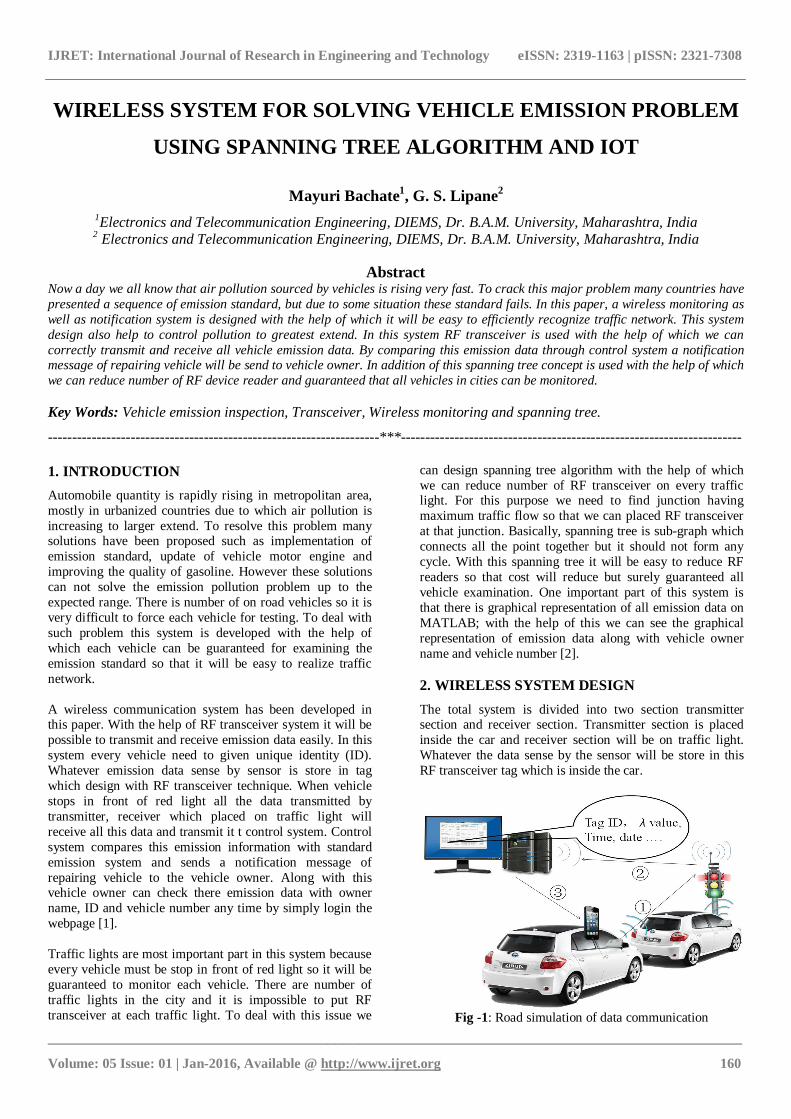
can design spanning tree algorithm with the help of which we can reduce number of RF transceiver on every traffic light. For this purpose we need to find junction having maximum traffic flow so that we can placed RF transceiver at that junction. Basically, spanning tree is sub-graph which connects all the point together but it should not form any cycle. With this spanning tree it will be easy to reduce RF readers so that cost will reduce but surely guaranteed all vehicle examination. One important part of this system is that there is graphical representation of all emission data on MATLAB; with the help of this we can see the graphical representation of emission data along with vehicle owner name and vehicle number [2]. 2. WIRELESS SYSTEM DESIGN The total system is divided into two section transmitter section and receiver section. Transmitter section is placed inside the car and receiver section will be on traffic light. Whatever the data sense by the sensor will be store in this RF transceiver tag which is inside the car.
Fig -1: Road simulation of data communication

IJRET: International Journal of Research in Engineering and Technology eISSN: 2319-1163 | pISSN: 2321-7308
_______________________________________________________________________________________ Volume: 05 Issue: 01 | Jan-2016, Available @ http://www.ijret.org 161
When the car stops in front of red light within this duration all the data will be transmitted by transmitter, receiver which is on traffic light will receive all this data and transmit it to control system as shown in figure 1. Control system compares this data and sends a notification message of repairing vehicle to the vehicle owner. Then this data again send to web page through Wi-Fi device. Here Wi-Fi device acts as server. 2.1 Emission Information Collection For the emission information collection and transmission RF transceiver tag and reader is designed. Sensors are connected across exhaust system between upstream and downstream of catalytic converter. All this emission information which is sense by sensor will be store in tag. When car stops in front of red light within this duration all this emission information will be transmitted by RF transceiver tag to the receiver. Firstly, all the emission from exhaust will be sense by sensor and this data in voltage form is given to the controller. An analog- to- digital converter convert this voltage value to digital number and then this digital data will be stored to RF transceiver tag. A prototype of transmitter section is shown in figure 2.
Fig -2: Transmitter section
Figure shows that in transmitter section tree sensors are interface with microcontroller so that all the output is in voltage form will be converted in to digital number for the further transmission [3]. 2.2 Emission information transmission Whatever the emission information transmitted by tag will be receive by reader which will be placed on traffic light. This updated information is again transmitted to the control system. Control system compares this information with emission standard and send notification message of repairing vehicle to the vehicle owner. Along with this vehicle owner can check there emission data any time by just simply login the webpage. In this system Wi-Fi device is used for the creation of webpage. Here Wi-Fi device act as server and GSM modem is for sending notification message. In webpage user can see the name along with ID and emission information. Figure shows receiver system as
reader along with interfacing of GSM modem and Wi-Fi device.
Fig -3: Receiver section
Block diagram of this system is also divided into two section transmitter section and receiver section. Figure 4 shows transmitter section in which carbon monoxide and hydrocarbon sensor interface with microcontroller. All the emission data of sensor in voltage form is converted into digital number by analog-to-digital converter and then this data is wirelessly transmitted to receiver.
Fig -4: Block diagram of transmitter section
Receiver receives this data wirelessly and given it to microcontroller. With the help of serial communication this data is given to Wi-Fi device which acts as server, with the help of this device webpage is created so that vehicle owner can check emission data any time by login the webpage.
Fig -5: Block diagram of receiver section

IJRET: International Journal of Research in Engineering and Technology eISSN: 2319-1163 | pISSN: 2321-7308
_______________________________________________________________________________________ Volume: 05 Issue: 01 | Jan-2016, Available @ http://www.ijret.org 162
There is serial communication between GSM modem and microcontroller, with the help of which notification message is generated by AT command. The purpose of using USB to UART module is that, we can see the graphical form of all emission data in MATLAB. 3. WIRELESS NOTIFICATION SYSTEM Wireless notification system is nothing but control system in which all the emission data collected from reader is being compared with emission standard and then a notification message of repairing car will be send to the vehicle owner. The schematic of message which will send to owner is shown in figure 6.
Fig -6: Schematic of notification message
Along with this vehicle owner can check their vehicle emission data with vehicle owner name and vehicle number any time by login the webpage. This technology is important part of this system with the help of which it is possible to easily realize green traffic network. There is also one important part of this system is that we can see graphical representation of all gas emission data on MATLAB as shown in figure 7.
Fig -7: Schematic of graphical representation on mat lab
This graphical representation shows emission data of carbon monoxide, hydrocarbon and temperature in graphical form along with vehicle owner name and vehicle number. The purpose of using temperature sensor is that just to check how the temperature of exhaust will be varied with increase in gas emission. 4. SPANNING TREE ALGORITHM Spanning tree algorithm is used for traffic light selection, in every city there are number of traffic lights are available and it is very difficult to situate this reader system at each traffic light for this purpose spanning tree algorithm is used. Spanning tree is sub-diagram or sub-tree that connects all the vertices without forming simple cycle. Spanning tree algorithm will be helpful to select traffic light having maximum traffic flow so that we can placed this system at particular traffic light. Because of this number of traffic lights for placing reader will be reduced to greater extend and therefore cost will be reduce and efficiency can be easily increase. To evaluate how the traffic light selection is done by considering the maximum traffic flow, consider one example of spanning tree as shown in figure 8.
Fig -8: An example of spanning tree
In above figure there are five vertices, here vertices means traffic lights which are placed at every junction. In this algorithm consider each edge as road and according to traffic flow we need to assign particular weight at each edge. Here weight means number of traffic flow. Each road means edges connected to each other and form a junction means vertices. A particular weight will be assigning to each edge according to individual traffic flow. There are five vertices V={1, 2, 3, 4, 5} and eight edges means roads which connect to each vertices E={(1,2), (1,3), (1,4), (2,5), (2,3), (3,5), (3,4), (4,5)}. Particular weight will be assign to each of these edges by considering individual vertices and each edge then following matrix D is formed [4]:

IJRET: International Journal of Research in Engineering and Technology eISSN: 2319-1163 | pISSN: 2321-7308
_______________________________________________________________________________________ Volume: 05 Issue: 01 | Jan-2016, Available @ http://www.ijret.org 163
Once we get matrix D, with the help of this matrix we can form a new matrix by considering maximum weight means highest traffic flow weight at individual column. If we consider such individual column of maximum weight a new matrix will be form, we called it as favored link matrix (FLM):
With the help of this link matrix we can form vertices set matrix by simply considering each pair of vertices for corresponding graph as follow:
By considering this vertices matrix each vertices again should be consider having maximum weight. If there is any repetition of vertices pair, the repeated pair will be removed. By applying this rule vertices set will be form with the help of which we can simply form a new spanning tree which should not form a cycle. Following is set of vertices having points (2, 1), (4, 1), (3, 2), (3, 4), (4, 3), (5, 2), (2, 5). Removing the repeated pair a new set will be as follow: (2, 1), (4, 1), (3, 2), (3, 4), (2, 5) With the help of this new set of vertices a new spanning tree will be form as shown in below figure 9.
Fig -9: Final spanning tree
In this way a spanning tree can be form with the help of which we can find a junction having maximum traffic flow so that reader can be placed at that traffic light and this will ensure to monitoring all traffic network in city.
5. CONCLUSIONS In this paper a wireless monitoring and notification system is designed with the help of which it will be easy to recognize traffic network. RF transceiver system is used to transmit and receive emission information. Here Wi-Fi device used as server for webpage creation with the help of which vehicle owner can easily check emission information. With the help of GSM modem a notification message will be send to vehicle owner. A spanning tree algorithm is used so that it will be easy to reduce number of reader placed on traffic light so that cost will be reduce and efficiency will be increase. REFERENCES [1] A. J. McMichael, "The urban environment and health
in a world of increasing globalization: Issues for developing countries," Bulletin of the World Health Organization, vol. 78, pp. 1117-1126, 2000.
[2] C. K. Chan and X. Yao, “Air pollution in mega cities in China,” Atmospheric Environment, vol. 42, pp. 1-42, 2008.
[3] D. S. Eisinger, "Evaluating inspection and maintenance programs: A policy-making framework," Journal of the Air & Waste Management Association, vol. 55, pp. 147-162, Feb 2005.
[4] D.P. Chock, S.L. Winkler, T.Y. Chang, S.J. Rudy, and Z.K. Shen, “Urban ozone air quality impact of emissions from vehicles using reformulated gasolines and M85”, Atmospheric Environment, Vol. 28, pp. 2777-2787, September 1994.
BIOGRAPHIES
B.E in ECE from M.I.T. Aurangabad, M.E in ETC, DIEMS, (worked on wireless system for temperature and humidity measurement), Maharashtra, India.