numerical analysis of geothermal tunnels -...
TRANSCRIPT
IJRET: International Journal of Research in Engineering and Technology eISSN: 2319-1163 | pISSN: 2321-7308
_______________________________________________________________________________________
Volume: 04 Issue: 02 | Feb-2015, Available @ http://www.ijret.org 740
NUMERICAL ANALYSIS OF GEOTHERMAL TUNNELS
Aparna Kanth1, Tanusree Chakraborty
2
1Asst. Professor, Civil Engg. Dept., S.I.E.T, Greater Noida, U.P, India-201308
2Asst. Professor, Civil Engg. Dept., IIT Delhi, India-110016
Abstract Geothermal energy is a good alternative of fossil fuels and its usage is the most innovative and useful technology that contributes
to environmental protection and provides substantial energy, long term cost savings and minimized maintenance. Geothermal
energy can be extracted or injected to the earth through tunnels, where tunnels acts as a heat exchanger, in which absorber pipes
are fitted, which are circulated with heat transfer liquid. In cities, tunnels provide access for rail, road and utilities. They can also
be used as ground heat exchanger for GSHP (Ground Source Heat Pump) systems. Tunnels dug underground use geothermal power to bring our home temperature to earth temperature, i.e helps in heating and cooling. The concept for the thermal tunnel
utilizes the temperature difference between the ground and inlet temperature, via compression (heating) or expansion (cooling), to
generate building heating or cooling. The system is reversible and operated at best efficiency between seasons. Response of the
tunnel as a element has to be recorded and studied. ABAQUS is finite element software (FEM) used for the analysis. Study deals
with the simulation of geothermal tunnels using ABAQUS, involving heat transfer analysis and coupled thermo-mechanical
analysis using a 3-D model. The model has been analysed for finding out thermal stresses, temperature and displacements on
concrete lining, embedded pipes and the soil in which tunnel is being constructed. Results are generated in the form of various
plots after running the analysis for a duration of 8 years.
Keywords: Geothermal tunnels, ABAQUS, FEM, GSHP, Coupled thermo-mechanical.
--------------------------------------------------------------------***----------------------------------------------------------------------
1. INTRODUCTION
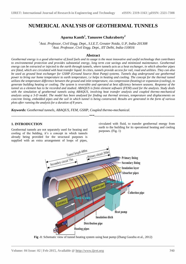
Geothermal tunnels are not separately used for heating and
cooling of the bulding, it’s a concept in which tunnels
already being provided for the structural purposes is
supplied with an extra arrangement of loops of pipes,
circulated with fluid, to transfer geothermal energy from
earth to the building for its operational heating and cooling
purposes. (Fig. 1)
Fig -1: Schematic view of tunnel heating system using heat pump (Zhang Guozhu et al., 2012)
IJRET: International Journal of Research in Engineering and Technology eISSN: 2319-1163 | pISSN: 2321-7308
_______________________________________________________________________________________
Volume: 04 Issue: 02 | Feb-2015, Available @ http://www.ijret.org 741
Being acting like a heat exchanger, tunnels are subjected to
additional thermal stresses which complicates their behavior
and it needs to be studied. When tunnels are provided and
used as heat exchanger also, they are acted upon by thermal
loads. The response of the tunnel as a element has to be
recorded and studied. Otherwise it may exceed the failure limits of the material. Therefore it is analysed by finite
element method techniques (FEM).
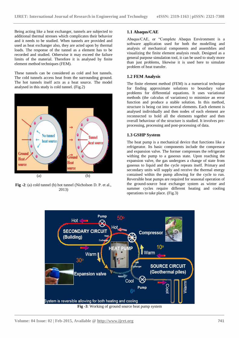
These tunnels can be considered as cold and hot tunnels.
The cold tunnels access heat from the surrounding ground.
The hot tunnels itself acts as a heat source. The model
analysed in this study is cold tunnel. (Fig.2)
(a) (b)
Fig -2: (a) cold tunnel (b) hot tunnel (Nicholson D. P. et al.,
2013)
1.1 Abaqus/CAE
Abaqus/CAE, or “Complete Abaqus Environment is a
software application used for both the modelling and
analysis of mechanical components and assemblies and
visualizing the finite element analysis result. Designed as a
general purpose simulation tool, it can be used to study more
than just problems, likewise it is used here to simulate problem of heat transfer.
1.2 FEM Analysis
The finite element method (FEM) is a numerical technique
for finding approximate solutions to boundary value
problems for differential equations. It uses variational
methods (the calculus of variations) to minimize an error
function and produce a stable solution. In this method,
structure is being cut into several elements. Each element is
analysed individually and then nodes of each element are
reconnected to hold all the elements together and then
overall behaviour of the structure is studied. It involves pre-
processing, processing and post-processing of data.
1.3 GSHP System
The heat pump is a mechanical device that functions like a
refrigerator. Its basic components include the compressor
and expansion valve. The former compresses the refrigerant
withing the pump to a gaseous state. Upon reaching the
expansion valve, the gas undergoes a change of state from
gaseous to liquid and the cycle repeats itself. Primary and
secondary units will supply and receive the thermal energy
contained within the pump allowing for the cycle to run.
Reversible heat pumps are required for seasonal operation of
the ground-source heat exchanger system as winter and
summer cycles require different heating and cooling
operations to take place. (Fig.3)
Fig -3: Working of ground source heat pump system
IJRET: International Journal of Research in Engineering and Technology eISSN: 2319-1163 | pISSN: 2321-7308
_______________________________________________________________________________________
Volume: 04 Issue: 02 | Feb-2015, Available @ http://www.ijret.org 742
Primary function of secondary unit is to utilize the extracted
thermal energy for heating purposes during the winter and to
receive unwanted heat from its surroundings in summer for
transfer into the ground.
1.4 Fully Coupled Thermo-mechanical Analysis
Temperature changes cause axial and radial deformation which affects the contact. Contact affects temperature, and
temperature distorts the parts, which affects the contact. The
system is thus fully coupled. The problem is thus solved
using fully coupled thermo-mechanical analysis capability
in ABAQUS/Standard.
2. PROBLEM STATEMENT AND 3-D ANALYSIS
The thermal tunnel design is based on modeling the heat
transfer from the tunnel air and the surrounding ground to
the water filled pipes in the segments. The model has been
caaliberated against periods with TES (thermal energy
segments) heat extraction rates of 10W/m2 and 30W/m2. A
generalized study is done for sandy soil. The soil’s and concrete’s behavior is modeled by using plasticity models in
finite element software ABAQUS.
2.1 Model Geometry
A circular tunnel can be constructed by assembling different
curved elements. Instead of analyzing the circular tunnel as
a whole, the curved elements are analysed neglecting the
curvature while forming the model.
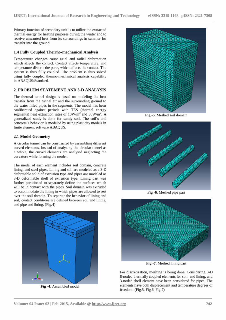
The model of each element includes soil domain, concrete
lining, and steel pipes. Lining and soil are modeled as a 3-D
deformable solid of extrusion type and pipes are modeled as
3-D deformable shell of extrusion type. Lining part was
further partitioned to separately define the surfaces which will be in contact with the pipes. Soil domain was extruded
to accommodate the lining in which pipes are allowed to rest
over the soil domain. To separate the behavior of lining and
soil, contact conditions are defined between soil and lining,
and pipe and lining. (Fig.4)
Fig -4: Assembled model
Fig -5: Meshed soil domain
Fig -6: Meshed pipe part
Fig -7: Meshed lining part
For discretization, meshing is being done. Considering 3-D
8-noded thermally coupled elements for soil and lining, and
3-noded shell element have been considered for pipes. The
elements have both displacement and temperature degrees of
freedom. (Fig.5, Fig.6, Fig.7)

IJRET: International Journal of Research in Engineering and Technology eISSN: 2319-1163 | pISSN: 2321-7308
_______________________________________________________________________________________
Volume: 04 Issue: 02 | Feb-2015, Available @ http://www.ijret.org 743
2.2 Material Properties
The plastic behavior of soil was modeled using the Mohr-
Coulomb constitutive plasticity model. Concrete damaged
plasticity model was used to capture the plastic behavior of
concrete. The soil properties also consisted of thermal
properties governing its thermal behavior. The properties of
soil like density (), modulus of elasticity (E), Poisson’s ratio (υ) are referred from book “Properties of Geotechnical
Engineering (5th Indian Edition)” by B.M. Das.
2.3 Boundary and Loading Conditions
Mechanical as well as temperature boundary conditions
were applied. Bottom of soil domain being fixed, sides of
the model given roller support and rest all faces were
allowed to deform. Pumps that are being used to circulate
water in the pipes are simulated by giving temperature
boundary condition in the pipes in the sinusoidal form as
shown (Fig.8) for extraction rates 30W and 10W applied in
the pipes.
Fig -8: Temperature variation in pipes
Above Fig.8 shows extraction of heat per m2 of tunnel is
more when pipes are at lower average temperature than
when they are at higher average temperature.
3. ANALYSIS OF 3-D MODEL
Transient state analysis is run by considering soil domain both as dense sand and loose sand as separate cases. Both
the analysis are run for two different extraction rates
separately i.e 30W/m2 and 10W/m2, analyzing tunnel as
geothermal tunnel. Each case is analyzed with combined
mechanical and thermal loads for heating and cooling,
applied for 8 years.
4. RESULTS AND DISCUSSIONS
The model has been analyzed for finding out the thermal
stresses, temperature, and displacements on concrete lining,
embedded pipes, and the soil in which tunnel is being
constructed. The results are being plotted in terms of
stresses v/s time, displacement v/s time and temperature v/s time plots.
0 1 2 3 4 5 6 7 8-12
-9
-6
-3
0
Dis
pla
cem
en
t (m
m)
Time (Yrs)
LINING
SOIL
PIPE
Fig -9:Displacement with time for 30W
0 1 2 3 4 5 6 7 8-12
-8
-4
0
Dis
pla
cem
en
t (m
m)
Time (Yrs)
LINING
SOIL
PIPE
Fig -10:Displacement with time for 10W
Soil is seen to be displaced more than lining and pipes and settlement being in the downward direction. (Fig.9, Fig.10)
0 1 2 3 4 5 6 7 80
15
30
45
Tem
pera
ture
(°C
)
Time (Yrs)
LINING
SOIL
PIPE
Fig -11:Temperature with time in for 30W
0 1 2 3 4 5 6 7 80
15
30
45
Tem
pera
ture
(°C
)
Time (Yrs)
LINING
SOIL
PIPE
Fig -12:Temperature with time in for 10W
Range of temperature variation is more for more extraction
rate. Specific heat of soil being higher than concrete than
steel, shows lesser temperature variation compared to other
two. (Fig.11, Fig.12)

IJRET: International Journal of Research in Engineering and Technology eISSN: 2319-1163 | pISSN: 2321-7308
_______________________________________________________________________________________
Volume: 04 Issue: 02 | Feb-2015, Available @ http://www.ijret.org 744
0 1 2 3 4 5 6 7 8-12
-8
-4
0
Str
ess (
MP
a)
Time (Yrs)
S11 LINING
Fig -13: Stress in lining with time for 30W
0 1 2 3 4 5 6 7 8-12
-8
-4
0
Str
ess (
MP
a)
Time (Yrs)
S11 LINING
Fig -14: Stress in lining with time for 10W
0 1 2 3 4 5 6 7 8-0.3
-0.2
-0.1
0.0
Str
ess (
MP
a)
Time (Yrs)
S11 SOIL
Fig -15: Stresses in soil with time for 30W
0 1 2 3 4 5 6 7 8-0.3
-0.2
-0.1
0.0
Str
ess (
MP
a)
Time (Yrs)
S11 SOIL
Fig -16: Stresses in soil with time for 10W
0 1 2 3 4 5 6 7 8-195
-190
-185
Str
ess (
MP
a)
Time (Yrs)
S11 PIPE
Fig -17: Stresses in pipe with time for 30W
0 1 2 3 4 5 6 7 8-195
-190
-185
Str
ess (
MP
a)
Time (Yrs)
S11 PIPE
Fig -18:Stresses in pipe with time for 10W
Magnitude of stresses does not vary much with the
extraction rates as can be seen from the plots for 30W and
10W. But this can be clearly seen that stresses induced in
pipes are very large compared to the stresses induced in
lining and soil domain. Though nature of stresses in all three
material is same, being compressive for all 8 years of
analysis and showing sinusoidal behavior throughout.
(Fig.13, Fig.14, Fig.15, Fig.16, Fig.17, Fig.18)
5. SITE VISIT
Neemrana is an ancient historical town in Alwar district of
Rajasthan, India, situated at 122 Km from Delhi on Delhi- Jaipur highway. Neemrana is the site of NIIT University
which won the India Today award for the Greenest Campus.
Type of soil available in Rajasthan is mostly sandy. Project
used in NIIT University is named as Earth Air-Tunnel and is
a perfect application of this project. The system uses only
30% of the energy that a normal air conditioning system
would use. In this system, fresh air is drawn through a long
underground duct, laid 4m below the ground called the earth
air tunnel. Heat exchange with the underground duct cools
down the air which is further treated for temperature,
humidity and dust before it is brought into the building and supplied to every room. This air cools down the room and is
exhausted through a chimney. The system works with 100%
fresh air and maintains a healthy environment inside.
NIIT university is spread over 100 acres of land in
Neemrana. Being situated in Rajasthan, its surrounding has
very dry hot air with its temperature reaching to about 45°C,
which makes the survival hard for the dwellers. For the
comfortable stay of students, university has provided each
one of them with AC’s in their rooms, though its hard to
believe but it is not less than that. This is made possible by the use of renewable energy source i.e geothermal energy
and construction of earth air tunnel.
Intake towers are constructed as shown in Fig.19, 5m deep
and 12m tall to collect dry hot air from the surroundings,
fitted with various filters to purify air from dust particles. 10
such towers are being constructed. 5m down the ground
level, 120m long tunnels are being constructed of diameter
1.2m with sandy soil all around. 14 such tunnels are being
constructed. Earth temperature which is found to be 30°C
led to the fall of air temperature from 45°C to somewhere
around 33°C. This air is further taken to the air handling unit
IJRET: International Journal of Research in Engineering and Technology eISSN: 2319-1163 | pISSN: 2321-7308
_______________________________________________________________________________________
Volume: 04 Issue: 02 | Feb-2015, Available @ http://www.ijret.org 745
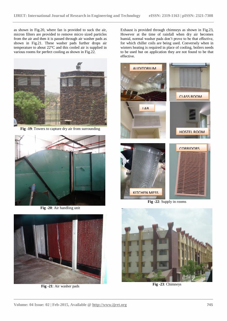
as shown in Fig.20, where fan is provided to suck the air,
micron filters are provided to remove micro sized particles
from the air and then it is passed through air washer pads as
shown in Fig.21. These washer pads further drops air
temperature to about 22°C and this cooled air is supplied in
various rooms for perfect cooling as shown in Fig.22.
Fig -19: Towers to capture dry air from surrounding
Fig -20: Air handling unit
Fig -21: Air washer pads
Exhaust is provided through chimneys as shown in Fig.23,
However at the time of rainfall when dry air becomes
humid, normal washer pads don’t prove to be that effective,
for which chiller coils are being used. Conversely when in
winters heating is required in place of cooling, boilers needs
to be used but on application they are not found to be that effective.
Fig -22: Supply in rooms
Fig -23: Chimneys
AUDITORIUM
CLASS ROOM
LAB
HOSTEL ROOM
KITCHEN MESS
CORRIDORS
IJRET: International Journal of Research in Engineering and Technology eISSN: 2319-1163 | pISSN: 2321-7308
_______________________________________________________________________________________
Volume: 04 Issue: 02 | Feb-2015, Available @ http://www.ijret.org 746
6. CONCLUSIONS
The design is linked to hot tunnels where heat is extracted
from the tunnel air and transferred to the surface for
domestic hot water production and heating. The results for
temperature, thermal stresses and displacements are
produced after the transient state analysis is run successfully
for 8 years.
The thermal tunnel design is based on modeling the heat
transfer from the tunnel air and the surrounding ground to
the water filled pipes in the segments. The ABAQUS
numerical model is used to assess this transfer. The model
has been calibrated against periods with TES heat extraction
rates of 30W/m2 and 10W/m2 for sandy soil.
It is known that compressive strength of steel is 250-500
MPa, that of concrete is 15-20 MPa depending upon the
grade of concrete and that of sand is 0.2 to 0.6 MPa. Thus
from the results and plots obtained, it can be inferred that stresses induced due to temperature variation and the
displacements caused in all three i.e lining, pipes and soil
are within permissible limits and hence forth tunnels already
constructed for transportation purpose can be put to be used
as GSHP system for heat extraction from soil and supplying
it in building on earth.
ACKNOWLEDGEMENTS
The authors would like to express their deep gratitude
towards high authorities in NIIT University who allowed a
campus visit to their university to understand the practical
utility of this project work. They would also like to thank
the members of Project Evaluation Committee and Geotechnical faculty of IIT Delhi, for their comments and
valuable suggestions to improve the quality of this work.
REFERENCES
[1]. Nicholson, D. P., Chen, Q., Pillai, A., & Chendorain, M.
(2013). Developments in thermal pile and thermal tunnel
linings for city scale GSHP systems. In Proceedings of the
38th Workshop on Geothermal Reservoir Engineering.
[2]. Rybach, L. (1995). “Thermal waters in deep alpine
tunnels.” Geothermics, 24(5), 631-637.
[3]. ZHANG, G., Xia, C. C., Ma, X. G., LI, P., & WEI, Q.
(2012). “Rock-soil thermal response test of tunnel heating
system using heat pump in cold region.” Chinese Journal of Rock Mechanics and Engineering, 31(1), 99-105.
[4]. Rybach, L., Wilhelm, J., & Gorhan, H. (2003,
September). “Geothermal use of tunnel waters—a Swiss
specialty.” In International Geothermal Conference,
Reykjavík, Session (Vol. 5).
[5]. Lienau, P. J., & Lund, J. W. (1974). “Multipurpose use
of geothermal energy.” (No. OIT-74-1Z). Oregon Institute
of Technology, Klamath Falls, OR.
[6]. Hwang, S., Ooka, R., & Nam, Y. (2010). “Evaluation of
estimation method of ground properties for the ground
source heat pump system.” Renewable energy,35(9), 2123-2130.
BIOGRAPHIES
Aparna Kanth, is an Assistant Professor
in Civil Engg. Dept. of Skyline Institute
of Engg. and Tech., Greater Noida, U.P,
India-201308
M.Tech is completed in Geotechnical Engg. from IIT Delhi,
Dr.Tanusree Chakraborty is an Assistant
Professor in Civil Engg. Dept. of IIT
Delhi, Delhi, India-110016 (email-
[email protected]) Ph.D is
completed from Purdue University,
West Lafayette, USA.