wireless sensors - mywww zhaw · pdf filewireless sensors a modern approach ... f = 402 mhz...
TRANSCRIPT

1
Wireless Sensors
A Modern Approachto Eliminate Cabling
29.10.2002© Elektrobit AG, <wireless sensor.ppt> 2
What Wireless can do
• The fundamental formula:
• Pr = received power• Pt = transmitted power• λ = wavelength• d = distance• n = propagation exponent• L = system loss factor
Ld4GrGtPtPr n2
2
•••••
=)( π
λ

2
29.10.2002© Elektrobit AG, <wireless sensor.ppt> 3
What Wireless can do
Check health of a eagle anywhere in the world using LEO satellitesf = 402 MHz (wavelength λ = c / f= 75 cm),Pt = 100 mW, Pr > 10-16 W ( assumes B=1 kHz, NF = 4 dB, SNR=10 dB)Gr = 1 (Piece of Wire), Gt = 10 (Satellite Antenna), L = 2Freespace Propagation n = 2
Energy:120mA every 10 min. for 1 s from 2000 Ah Li-Cell:10’000 hour lifetime (>1 year)
km42002LPr4
GrGtPtd 2
2
=•••••
=)( π
λIt can be done: ARGOS 850 km
29.10.2002© Elektrobit AG, <wireless sensor.ppt> 4
What Wireless can do
Monitor the temperature of machinery tools anywhere in the plantf = 868 MHz (wavelength λ = c/f= 35 cm),Pt = 10 mW, Pr > 10-15 W ( assumes B=10 kHz, NF = 4 dB, SNR=10 dB)Gr = 4 (directional antenna), Gt = 1 (printed loop),L = 100 (fading margin for moving objects), Non line of sight propagation n = 4....6
Energy:20mA every second. for 100 ms from 2000 Ah Li-Cell:1’000 hour lifetime (>1 month)
m1334LPr4
GrGtPtd 2
2
=•••••
=)( π
λ m266LPr4
GrGtPtd 2
2
=•••••
=)( π
λ
It may be a hard job: optimized solutions

3
29.10.2002© Elektrobit AG, <wireless sensor.ppt> 5
Frequency Bands
Different countries-
Different regulations
e.g. CEPT Short Range Devices SRD
29.10.2002© Elektrobit AG, <wireless sensor.ppt> 6
Frequency Bands
4
29.10.2002© Elektrobit AG, <wireless sensor.ppt> 7
Frequency Bands
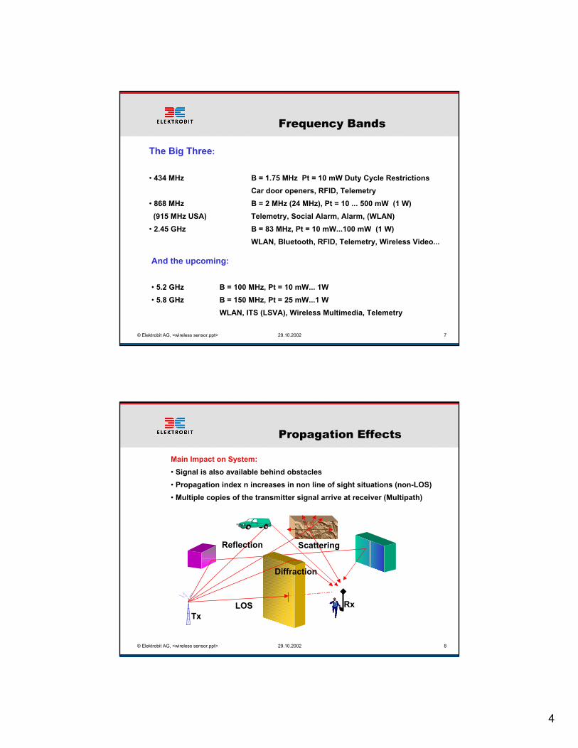
The Big Three:
• 434 MHz B = 1.75 MHz Pt = 10 mW Duty Cycle Restrictions Car door openers, RFID, Telemetry
• 868 MHz B = 2 MHz (24 MHz), Pt = 10 ... 500 mW (1 W) (915 MHz USA) Telemetry, Social Alarm, Alarm, (WLAN)• 2.45 GHz B = 83 MHz, Pt = 10 mW...100 mW (1 W)
WLAN, Bluetooth, RFID, Telemetry, Wireless Video...
And the upcoming:
• 5.2 GHz B = 100 MHz, Pt = 10 mW... 1W• 5.8 GHz B = 150 MHz, Pt = 25 mW...1 W
WLAN, ITS (LSVA), Wireless Multimedia, Telemetry
29.10.2002© Elektrobit AG, <wireless sensor.ppt> 8
Propagation Effects
TxRxLOS
ScatteringReflection
Diffraction
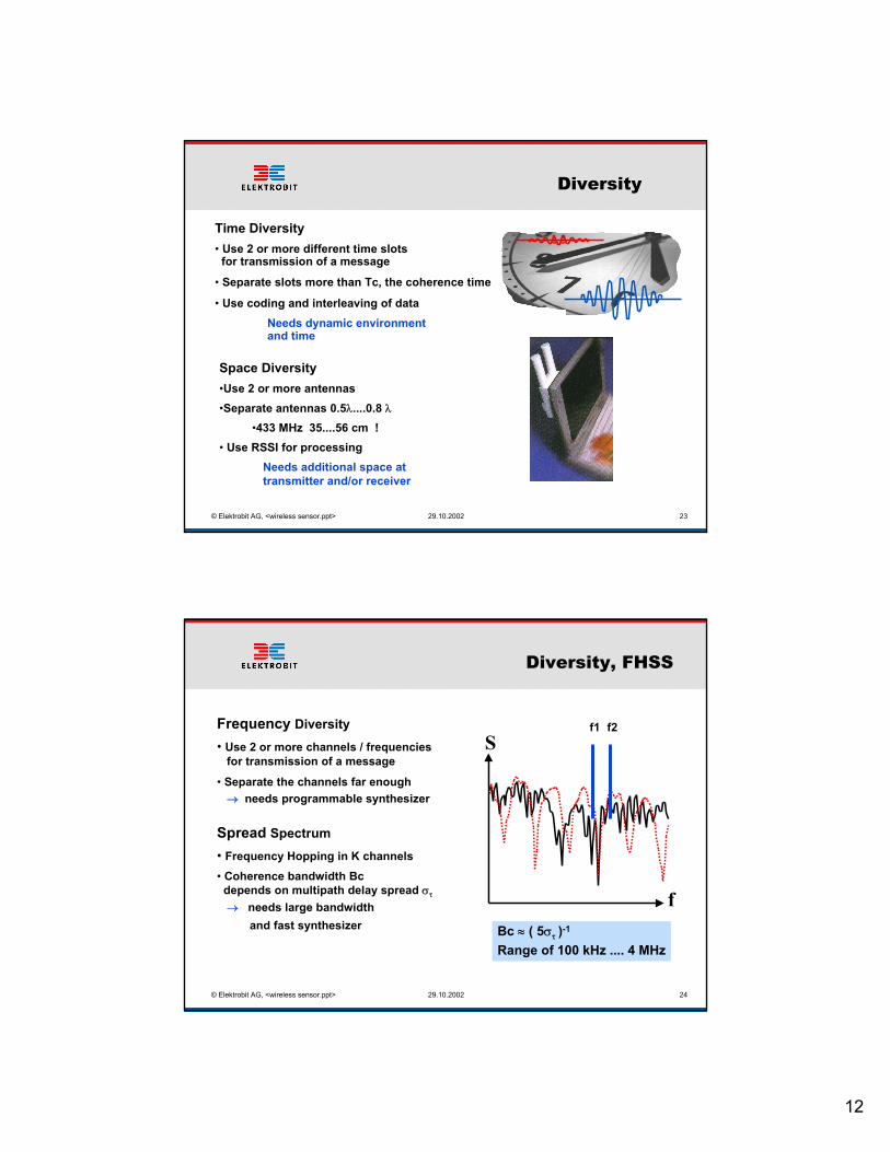
Main Impact on System:• Signal is also available behind obstacles• Propagation index n increases in non line of sight situations (non-LOS)• Multiple copies of the transmitter signal arrive at receiver (Multipath)

5
29.10.2002© Elektrobit AG, <wireless sensor.ppt> 9
Propagation Effects
Environment Propagation exponent n
Free Space 2Open Field (far) 4Urban area 2.5 - 4Shadowed urban 5 - 6In building LOS 1.8 - 2In building obstructed 4 - 6
Max useful path loss is typically 120 dB
29.10.2002© Elektrobit AG, <wireless sensor.ppt> 10
Propagation Effects
• Multipath signals can add or subtract → Deep fade notches can occur, L increases• Multipath changes when objects are moving
0 dB
-30 dB
840 MHz 880 MHzfrequency
SpectraCHx
20log [S(f, t1)]
20log [S(f, t2)]

6
29.10.2002© Elektrobit AG, <wireless sensor.ppt> 11
Propagation Effects
Reliability in % Fading margin (L) in dB
low reliable link90 1099 2099.9 3099.99 40
high reliable link
• 1 Channel curve is valid for low cost system without diversity• Diversity of 2 can bring 10... 20 dB reduction in margin !!
29.10.2002© Elektrobit AG, <wireless sensor.ppt> 12
Transmitter / Receiver
Low cost architecture
Synthesizer
PLL
VCO
Slicer
Tx/RxSwitch
IF
RF
Data
Antenna
Microcontroller
Gt / Gr
B
NF
λ S/N
Pt
Pr

7
29.10.2002© Elektrobit AG, <wireless sensor.ppt> 13
Transmitter / Receiver
LoopAntenna
Low cost architecture
• single channel• fixed output power • low Rx sensitivity • simple filtering
• external µC• simple detector• no error correction• no networking
29.10.2002© Elektrobit AG, <wireless sensor.ppt> 14
Receiver sensitivity
S/N
BER
Parameters influencing receiver sensitivity• Bit Error Rate (BER): related to link reliability• Modulation: Amplitude/Frequency/Phase: PSK, FSK, OOK... best for sensor application• Noise figure (NF) of receiver front-end: technology, price• Bandwidth B: proportional to data rate
1030Pr
mindBm
dBm
10Pr
S/Nlog(B)10NF dBm -174PrRkB
−
=
+•++=•=
PSK = phase shift keyingFSK = frequency shift keyingOOK = on-off (amplitude) keying

8
29.10.2002© Elektrobit AG, <wireless sensor.ppt> 15
1030)dBmPr(
min
10Pr
S/Nlog(B)10NF dBm -174Pr(dBm)RkB
−
=
+•++=•=
Receiver sensitivity
Example: Data rate R = 10 kbit/s, NF = 4 dB BER < 0.001 FSK, k = 1.0
S/N
BERB = 10 kHzPr(dBm) = -174 + 4 + 40 + 11 = -110 dBm
→ Pr = 10-14 W
29.10.2002© Elektrobit AG, <wireless sensor.ppt> 16
Antenna Design
• The antenna is the interface between transmitter or receiver and the propagation medium• It is therefore a deciding factor in the performance of a radio system• Principal properties are the same for transmitting and receiving antennas
Key parameters:BandwidthGain, Directivity, AreaImpedance matching

9
29.10.2002© Elektrobit AG, <wireless sensor.ppt> 17
Most important type of antennas
Monopole / Dipole
+ cheap+ wide bandwidth+ fair gain, omnidirectional- size is λ/4... λ- place dipole away from metall/ground- monopole needs ground plane
Antenna gain:
•λ /2 Dipole: Gr = 1.6• λ/4 Monopole Gr = 3.2• 5 λ/8 Monopole Gr = 6.4
λ /2
λ /2λ /4
29.10.2002© Elektrobit AG, <wireless sensor.ppt> 18
Most important type of antennas
Directional Patch
+ wide bandwidth+ high gain: Gr = 4...10+ easy placing on metall+ easy forming of arrays: Gr >10- size is λ/2 • λ/2- higher costs + - high directivity
OmnidirectionalDirectional
air printed

10
29.10.2002© Elektrobit AG, <wireless sensor.ppt> 19
Most important type of antennas
Small Printed LoopExample for 434 MHz:
+ small and cheap- narrow bandwidth- low gain when small- place away from metall/ground yresistivit
skindeepthwidthlenghtR
NA320R
l
4
22
r
••
=
••=
λπ )(
lr
r
RRR100Efficiency+
•=(%)
29.10.2002© Elektrobit AG, <wireless sensor.ppt> 20
New antenna technologies
• High frequency ceramic solutions (LTCC technology)
• Research on fractal antennas for reduced size of loop and dipoles
Application size for full gain at 2.4 GHz, Gr = 1
868 MHz: ∅ only 55 mm for Gr = 1

11
29.10.2002© Elektrobit AG, <wireless sensor.ppt> 21
Power source
If there is no wired power supply:• Energy is the most valuable resource• All components must support low power modes• What software can do to conserve energy: save power by turning radio off, when nothing is to hear
Xmit:
Recv:
preamble messagesleepb
Activesleep Activesleep
µs time scale
ms time scale
29.10.2002© Elektrobit AG, <wireless sensor.ppt> 22
Power source
But what does this mean for Pt = 1 mW link?
– Lithium Battery runs for 28 hours at peak load and years atminimum load!3 orders of magnitude difference
– A one byte transmission uses same energy as approx 10’000 cyclesof computation!Use software to increase performance
CR2354 560 mAh
003 mAEE-Prom
7 mA00
5 mA (RX)2 mA
Idle
10 uA20 mA01 mA04 mASensor Part
5 µA7 mA (TX)Radio5 µA5 mACPU
SleepActive
Wake-upSum
12
29.10.2002© Elektrobit AG, <wireless sensor.ppt> 23
Diversity
Time Diversity• Use 2 or more different time slots for transmission of a message
• Separate slots more than Tc, the coherence time
• Use coding and interleaving of dataNeeds dynamic environment and time
Space Diversity•Use 2 or more antennas•Separate antennas 0.5λ....0.8 λ
•433 MHz 35....56 cm !• Use RSSI for processing
Needs additional space at transmitter and/or receiver
29.10.2002© Elektrobit AG, <wireless sensor.ppt> 24
Diversity, FHSS
Frequency Diversity• Use 2 or more channels / frequencies for transmission of a message• Separate the channels far enough → needs programmable synthesizer
Spread Spectrum• Frequency Hopping in K channels• Coherence bandwidth Bc depends on multipath delay spread στ → needs large bandwidth and fast synthesizer
f
Sf1 f2
Bc ≈ ( 5στ )-1 Range of 100 kHz .... 4 MHz

13
29.10.2002© Elektrobit AG, <wireless sensor.ppt> 25
Undetected error Pb
Error correction
• Interleave data from different blocks
• Use forward error correction instead of simple parity check
• Golay (23.12) can correct 3 errors, detect 4 and more errors (B.Sklar)
Forward Error Correction (FEC)• Channel may show fading• Channel may be disturbed by jamming signal
29.10.2002© Elektrobit AG, <wireless sensor.ppt> 26
Error correction
Designing reliability in wireless link:
16e
7eundet )p(1)p(253P −••≈
•pe = uncoded error probability (@ same message duration)• For Eb/Noinformation bit = 7 dB → pe ≈ 10-2 → Pundet = 2·10-12
• If data rate is 10 kbit/s continuously: undetected error every 530 days !
Sophisticated error correction and data link layer protocol needed
• Golay (23,12) undetected error probability:
14
29.10.2002© Elektrobit AG, <wireless sensor.ppt> 27
Connectivity
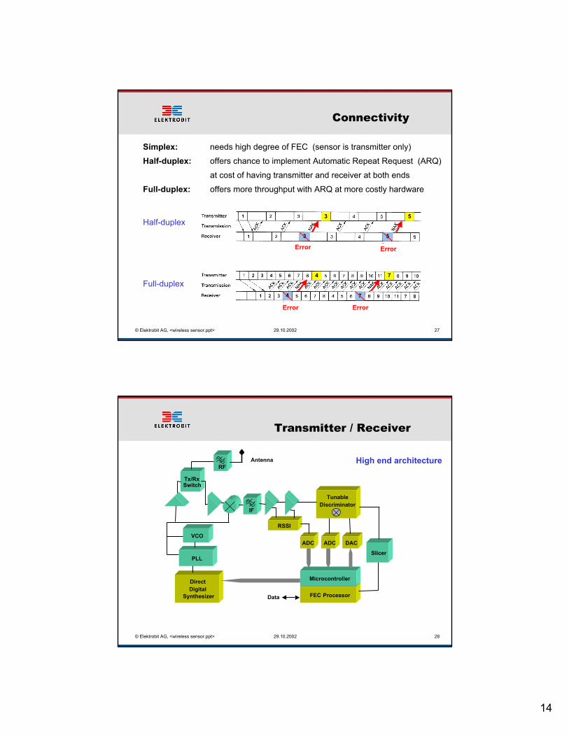
Simplex: needs high degree of FEC (sensor is transmitter only)Half-duplex: offers chance to implement Automatic Repeat Request (ARQ) at cost of having transmitter and receiver at both endsFull-duplex: offers more throughput with ARQ at more costly hardware
Half-duplex
Full-duplex
3 5
4 7
53
4 7
Error Error
Error Error
29.10.2002© Elektrobit AG, <wireless sensor.ppt> 28
Transmitter / Receiver
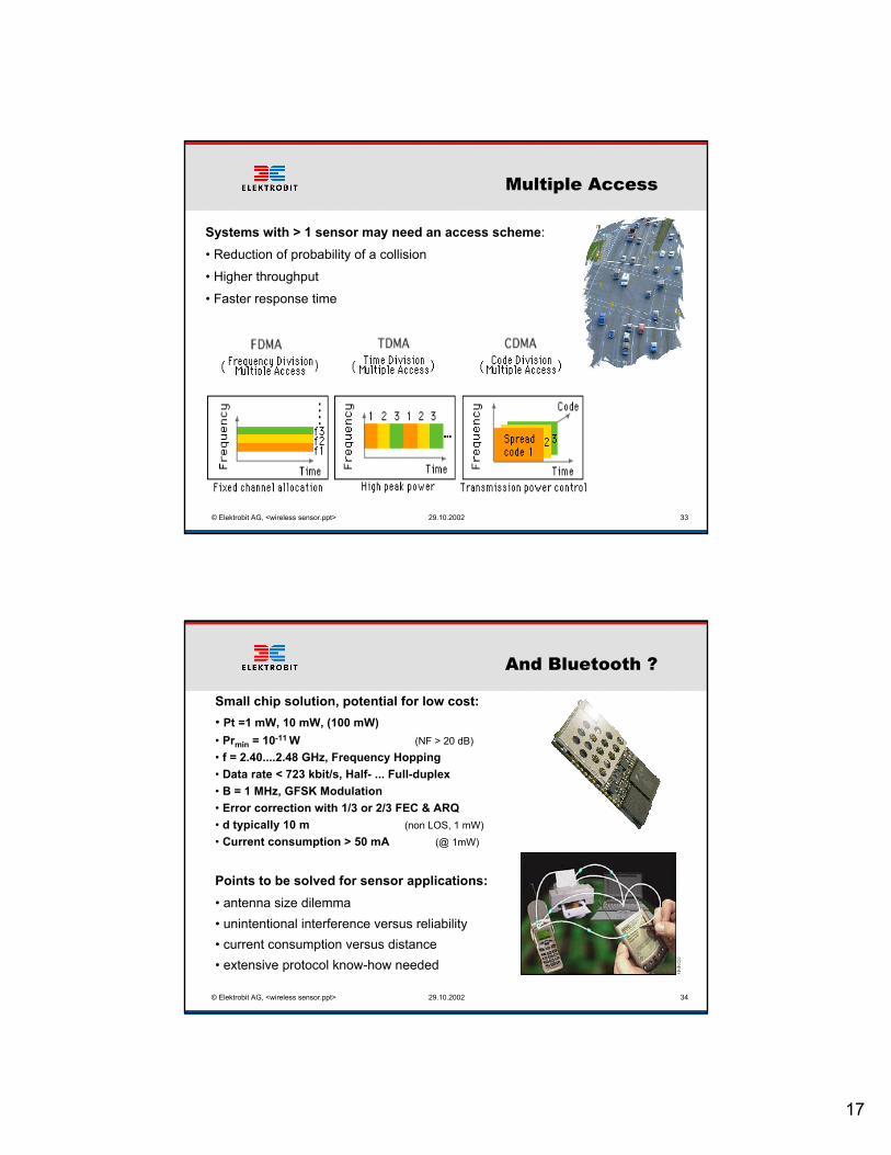
High end architecture
Direct Digital
Synthesizer
PLL
RSSI
ADC DACVCO
TunableDiscriminator
FEC Processor
Slicer
ADC
Tx/RxSwitch
IF
RF
Data
Antenna
Microcontroller

15
29.10.2002© Elektrobit AG, <wireless sensor.ppt> 29
Data Link Layer
Adapted Data Frames: simple but powerfull
• Learning sequence for adjusting discriminator/slicer for offsets • Barker sequence for bit and byte synchronization • Data blocks followed by forward error correction (FEC)• FH mode could send one frame per hop
Example for 50 kbit/s and 500 hops/s:
Hopping Time 2 ms
1 Byte 160 µs
FEC FEC FECAdress
29.10.2002© Elektrobit AG, <wireless sensor.ppt> 30
Transmitter / Receiver
High end architecture
• Multi channel, FH• High Rx sensitivity• Onboard processor• Error correction• Networking support• Adaptive features
Tx/RxSwitch
LNAPA
Transceiver Host Interface
Sensor Codec
Generic TRX
Power Mgmt

16
29.10.2002© Elektrobit AG, <wireless sensor.ppt> 31
Wireless networks
Many topologies: Point to Point, Multi-point, Ad-hoc, Avalanche, Centralized.....
29.10.2002© Elektrobit AG, <wireless sensor.ppt> 32
Wireless networks
Application LayerPresentation Layer
Session LayerTransport LayerNetwork Layer
Physical LayerData Link Layer
Additional protocol layers need to be optimized for wireless
Example for Bluetooth:
Minimum needed for sensor
ISI / OSI
17
29.10.2002© Elektrobit AG, <wireless sensor.ppt> 33
Multiple Access
Systems with > 1 sensor may need an access scheme:• Reduction of probability of a collision• Higher throughput• Faster response time
29.10.2002© Elektrobit AG, <wireless sensor.ppt> 34
And Bluetooth ?
Small chip solution, potential for low cost: • Pt =1 mW, 10 mW, (100 mW)• Prmin = 10-11 W (NF > 20 dB)• f = 2.40....2.48 GHz, Frequency Hopping• Data rate < 723 kbit/s, Half- ... Full-duplex• B = 1 MHz, GFSK Modulation• Error correction with 1/3 or 2/3 FEC & ARQ• d typically 10 m (non LOS, 1 mW)• Current consumption > 50 mA (@ 1mW)
Points to be solved for sensor applications: • antenna size dilemma• unintentional interference versus reliability• current consumption versus distance• extensive protocol know-how needed

18
29.10.2002© Elektrobit AG, <wireless sensor.ppt> 35
Conclusions
Wireless Sensors - Means not just cutting the cables !
• Study propagation issues• Check regulatory options• Map system application to
•wireless architecture•modulation & diversity•data reliability & protocol•network aspects
• Design wireless circuits & antenna• Solve the power puzzle
29.10.2002© Elektrobit AG, <wireless sensor.ppt> 36
Conclusions
Wireless communications solutions• BLUETOOTHTM HW Integration• Elektrobit BLUETOOTHTM Stack• DECT / GSM / GPRS / HSCSD / WLAN• Radio Control / Telemetry System Design
Robust Data Communication• Spread Spectrum Technology (DSSS, FHSS)• High data rate
Integrated wireless systems• Low power / low cost radio (network) solutions• IC and RFIC Design • Embedded SW, TCP/IP, WEB
Elektrobit has the keys to your successful wireless application