wireless information and power transfer: … information and power transfer: architecture design and...
TRANSCRIPT
arX
iv:1
205.
0618
v3 [
cs.IT
] 6
Sep
201
31
Wireless Information and Power Transfer:Architecture Design and Rate-Energy Tradeoff
Xun Zhou, Rui Zhang, and Chin Keong Ho
Abstract—Simultaneous information and power transfer overthe wireless channels potentially offers great convenience tomobile users. Yet practical receiver designs impose technicalconstraints on its hardware realization, as practical circuits forharvesting energy from radio signals are not yet able to decodethe carried information directly. To make theoretical progress,we propose a general receiver operation, namely,dynamic powersplitting (DPS), which splits the received signal with adjustablepower ratio for energy harvesting and information decoding,separately. Three special cases of DPS, namely,time switching(TS), static power splitting (SPS) andon-off power splitting (OPS)are investigated. The TS and SPS schemes can be treatedas special cases of OPS. Moreover, we propose two types ofpractical receiver architectures, namely, separated versus inte-grated information and energy receivers. The integrated receiverintegrates the front-end components of the separated receiver,thus achieving a smaller form factor. The rate-energy tradeofffor the two architectures are characterized by a so-calledrate-energy (R-E) region. The optimal transmission strategy is derivedto achieve different rate-energy tradeoffs. With receivercircuitpower consumption taken into account, it is shown that the OPSscheme is optimal for both receivers. For the ideal case whenthe receiver circuit does not consume power, the SPS scheme isoptimal for both receivers. In addition, we study the performancefor the two types of receivers under a realistic system setupthatemploys practical modulation. Our results provide useful insightsto the optimal practical receiver design for simultaneous wirelessinformation and power transfer (SWIPT).
Index Terms—Simultaneous wireless information and powertransfer (SWIPT), rate-energy region, energy harvesting,wirelesspower, circuit power.
I. I NTRODUCTION
Harvesting energy from the environment is a promisingapproach to prolong the lifetime of energy constrained wirelessnetworks. Among other renewable energy sources such as solarand wind, background radio-frequency (RF) signals radiatedby ambient transmitters can be a viable new source forwireless power transfer (WPT). On the other hand, RF signalshave been widely used as a vehicle for wireless informationtransmission (WIT). Simultaneous wireless information andpower transfer (SWIPT) becomes appealing since it realizesboth useful utilizations of RF signals at the same time, andthus potentially offers great convenience to mobile users.
This paper has been presented in part at IEEE Global CommunicationsConference (Globecom), December 3-7, 2012, California, USA.
X. Zhou is with the Department of Electrical and Computer Engineering,National University of Singapore (e-mail: [email protected]).
R. Zhang is with the Department of Electrical and Computer Engineering,National University of Singapore (e-mail: [email protected]). He is alsowith the Institute for Infocomm Research, A*STAR, Singapore.
C. K. Ho is with the Institute for Infocomm Research, A*STAR,Singapore(e-mail: [email protected]).
Simultaneous information and power transfer over the wire-less channels has been studied in [1]–[9]. Varshney firstproposed the idea of transmitting information and energysimultaneously in [1]. A capacity-energy function was pro-posed to characterize the fundamental performance tradeoff forsimultaneous information and power transfer. In [2], Groverand Sahai extended the work in [1] to frequency-selectivechannels with additive white Gaussian noise (AWGN). It wasshown in [2] that a non-trivial tradeoff exists for informationtransfer versus energy transfer via power allocation. Wire-less information and power transfer subject to co-channelinterference was studied in [3], in which optimal designs toachieve different outage-energy tradeoffs as well as rate-energytradeoffs are derived. Different from the traditional viewoftaking interference as an undesired factor that jeopardizes thewireless channel capacity, in [3] interference was utilized as asource for energy harvesting. Unlike [1]–[3], which consideredpoint-to-point single-antenna transmission, [4]–[6] consideredmultiple-input multiple-output (MIMO) systems for SWIPT.In particular, [4] studied the performance limits of a three-node MIMO broadcasting system, where one receiver harvestsenergy and another receiver decodes information from thesignals sent by a common transmitter. [5] extended the workin [4] by considering imperfect channel state information(CSI) at the transmitter. MIMO relay systems involving anenergy harvesting receiver were studied in [6], in which thejoint optimal source and relay precoders were designed toachieve different tradeoffs between the energy transfer and theinformation rates. SWIPT for multi-user systems was studiedin [7]. It was shown in [7] that for multiple access channelswith a received energy constraint, time-sharing is necessaryto achieve the maximum sum-rate when the received energyconstraint is sufficiently large; while for the multi-hop channelwith a harvesting relay, the transmission strategy dependsonthe quality of the second link. Networks that involve wirelesspower transfer were studied in [8], [9]. In [8], the authorsstudied a hybrid network which overlays an uplink cellularnetwork with randomly deployed power beacons that chargemobiles wirelessly. Under an outage constraint on the datalinks, the tradeoffs between the network parameters were de-rived. In [9], the authors investigated a cognitive radio networkpowered by opportunistic wireless energy harvesting, wheremobiles from the secondary network either harvest energyfrom nearby transmitters in a primary network, or transmitinformation if the primary transmitters are far away. Underanoutage constraint for coexisting networks, the throughputofthe secondary network was maximized.
Despite the recent interest in SWIPT, there remains two key
2
challenges for practical implementations. First, it is assumedin [1], [2] that the receiver is able to observe and extract powersimultaneously from the same received signal. However, thisassumption may not hold in practice, as practical circuits forharvesting energy from radio signals are not yet able to decodethe carried information directly. Due to this potential limita-tion, the results in [1], [2] actually provided only optimisticperformance bounds. To coordinate WIT and WPT at thereceiver side, two practical schemes, namely, time switching(TS) and static power splitting (SPS), were proposed in [4].Second, the conventional information receiver architecturedesigned for WIT may not be optimal for SWIPT, due to thefact that WIT and WPT operate with very different powersensitivity at the receiver (e.g., -10dBm for energy receiversversus -60dBm for information receivers). Thus, for a systemthat involves both WIT and WPT, the receiver architectureshould be optimized for WPT. In addition, circuit powerconsumed by information decoding becomes a significantdesign issue for simultaneous information and power transfer,since the circuit power reduces the net harvested energy thatcan be stored in the battery for future use. In particular, theactive mixers used in conventional information receiver for RFto baseband conversion are substantially power-consuming. Itthus motivates us to propose new receiver architectures whichconsume less power by avoiding the use of active devices.
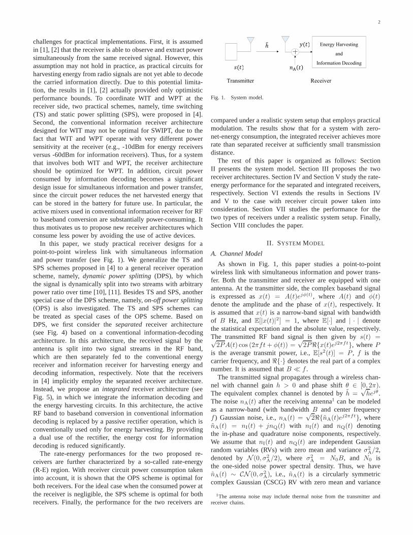
In this paper, we study practical receiver designs for apoint-to-point wireless link with simultaneous informationand power transfer (see Fig. 1). We generalize the TS andSPS schemes proposed in [4] to a general receiver operationscheme, namely,dynamic power splitting (DPS), by whichthe signal is dynamically split into two streams with arbitrarypower ratio over time [10], [11]. Besides TS and SPS, anotherspecial case of the DPS scheme, namely,on-off power splitting(OPS) is also investigated. The TS and SPS schemes canbe treated as special cases of the OPS scheme. Based onDPS, we first consider theseparated receiver architecture(see Fig. 4) based on a conventional information-decodingarchitecture. In this architecture, the received signal bytheantenna is split into two signal streams in the RF band,which are then separately fed to the conventional energyreceiver and information receiver for harvesting energy anddecoding information, respectively. Note that the receiversin [4] implicitly employ the separated receiver architecture.Instead, we propose anintegrated receiver architecture (seeFig. 5), in which we integrate the information decoding andthe energy harvesting circuits. In this architecture, the activeRF band to baseband conversion in conventional informationdecoding is replaced by a passive rectifier operation, whichisconventionally used only for energy harvesting. By providinga dual use of the rectifier, the energy cost for informationdecoding is reduced significantly.
The rate-energy performances for the two proposed re-ceivers are further characterized by a so-called rate-energy(R-E) region. With receiver circuit power consumption takeninto account, it is shown that the OPS scheme is optimal forboth receivers. For the ideal case when the consumed power atthe receiver is negligible, the SPS scheme is optimal for bothreceivers. Finally, the performance for the two receivers are
Energy Harvesting
and
Information Decoding
Transmitter Receiver
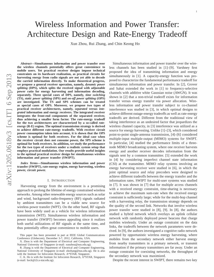
Fig. 1. System model.
compared under a realistic system setup that employs practicalmodulation. The results show that for a system with zero-net-energy consumption, the integrated receiver achievesmorerate than separated receiver at sufficiently small transmissiondistance.
The rest of this paper is organized as follows: SectionII presents the system model. Section III proposes the tworeceiver architectures. Section IV and Section V study the rate-energy performance for the separated and integrated receivers,respectively. Section VI extends the results in Sections IVand V to the case with receiver circuit power taken intoconsideration. Section VII studies the performance for thetwo types of receivers under a realistic system setup. Finally,Section VIII concludes the paper.
II. SYSTEM MODEL
A. Channel Model
As shown in Fig. 1, this paper studies a point-to-pointwireless link with simultaneous information and power trans-fer. Both the transmitter and receiver are equipped with oneantenna. At the transmitter side, the complex baseband signalis expressed asx(t) = A(t)ejφ(t), where A(t) and φ(t)denote the amplitude and the phase ofx(t), respectively. Itis assumed thatx(t) is a narrow-band signal with bandwidthof B Hz, andE[|x(t)|2] = 1, whereE[·] and | · | denotethe statistical expectation and the absolute value, respectively.The transmitted RF band signal is then given bys(t) =√2PA(t) cos (2πft+ φ(t)) =
√2Pℜ{x(t)ej2πft}, whereP
is the average transmit power, i.e.,E[s2(t)] = P , f is thecarrier frequency, andℜ{·} denotes the real part of a complexnumber. It is assumed thatB ≪ f .
The transmitted signal propagates through a wireless chan-nel with channel gainh > 0 and phase shiftθ ∈ [0, 2π).The equivalent complex channel is denoted byh =
√hejθ.
The noisenA(t) after the receiving antenna1 can be modeledas a narrow-band (with bandwidthB and center frequencyf ) Gaussian noise, i.e.,nA(t) =
√2ℜ{nA(t)e
j2πft}, wherenA(t) = nI(t) + jnQ(t) with nI(t) and nQ(t) denotingthe in-phase and quadrature noise components, respectively.We assume thatnI(t) and nQ(t) are independent Gaussianrandom variables (RVs) with zero mean and varianceσ2
A/2,denoted byN (0, σ2
A/2), where σ2A = N0B, and N0 is
the one-sided noise power spectral density. Thus, we havenA(t) ∼ CN (0, σ2
A), i.e., nA(t) is a circularly symmetriccomplex Gaussian (CSCG) RV with zero mean and variance
1The antenna noise may include thermal noise from the transmitter andreceiver chains.

3
LPF
LPF
ADC Decoder
RF band to baseband conversion Baseband
Fig. 2. Information receiver.
σ2A. Corrupted by the antenna noise, the received signaly(t)
is given byy(t) =√2ℜ{y(t)}, where the complex signaly(t)
is
y(t) =√hPx(t)ej(2πft+θ) + nA(t)e
j2πft. (1)
B. Information Receiver
First, we consider the case where the receiver shown inFig. 1 is solely an information receiver. Fig. 2 shows thestandard operations at an information receiver with coherentdemodulation (assuming that the channel phase shiftθ isperfectly known at the receiver). The received RF band signaly(t) is first converted to a complex baseband signalyb(t) andthen sampled and digitalized by an analog-to-digital converter(ADC) for further decoding. The noise introduced by the RFband to baseband signal conversion is denoted byncov(t) withncov(t) ∼ CN (0, σ2
cov). For simplicity, we assume an idealADC with zero noise2. The discrete-time ADC output is thengiven by
y[k] =√hPx[k] + nA[k] + ncov[k] (2)
wherek = 1, 2, . . ., denotes the symbol index.It follows from (2) that the equivalent baseband channel for
wireless information transmission is the well-known AWGNchannel:
Y =√hPX + Z (3)
where X and Y denote the channel input and output, re-spectively, andZ ∼ CN (0, σ2
A + σ2cov) denotes the complex
Gaussian noise (assuming independentnA(t) and ncov(t)).When the channel input is distributed asX ∼ CN (0, 1),the maximum achievable information rate (in bps/Hz) or thecapacity of the AWGN channel is given by [12]
R = log2
(
1 +hP
σ2A + σ2
cov
)
. (4)
C. Energy Receiver
Next, we consider the case where the receiver in Fig. 1is solely an energy receiver, and derive the average wirelesspower that can be harvested from the received signal. Fig.3 illustrates the operations of a typical energy receiver thatconverts RF energy directly via arectenna architecture [13]. Inthe rectenna, the received RF band signaly(t) is converted to a
2The general case with nonzero ADC noise is considered in Remark 5.1.
LPFDiode Battery
A B
Rectifier
Fig. 3. Energy receiver.
direct current (DC) signaliDC(t) by a rectifier, which consistsof a Schottky diode and a passive low-pass filter (LPF). TheDC signaliDC(t) is then used to charge the battery to store theenergy. With an input voltage proportional toy(t), the outputcurrenti(t) of a Schottky diode is given by [14]:
i(t) = Is
(
eγy(t) − 1)
= a1y(t)+a2y2(t)+a3y
3(t)+· · · (5)
whereIs denotes the saturation current,γ denotes the recip-rocal of the thermal voltage of the Schottky diode, and thecoefficientsan’s are given byan = Isγ
n/n!, n = 1, 2, . . .,due to the Taylor series expansion of the exponential function.
From (1), for convenience we re-expressy(t) as follows:
y(t) =√2ℜ{
√hPx(t)ej(2πft+θ) + nA(t)e
j2πft}=
√2µY(t) cos (2πft+ φY(t)) (6)
whereφY(t) = arctanµQ(t)µI(t)
and
µY(t) =√
µ2I (t) + µ2
Q(t) (7)
with
µI(t) =√hPA(t) cos (φ(t) + θ) + nI(t) (8)
µQ(t) =√hPA(t) sin (φ(t) + θ) + nQ(t). (9)
By substituting (6) into (5) and ignoring the higher-order(larger than two) terms ofy(t), sinceγy(t) is practically asmall number close to zero, we obtain
i(t) ≈√2a1µY(t) cos (2πft+ φY(t))
+ 2a2µ2Y(t) cos
2 (2πft+ φY(t))
= a2µ2Y(t) +
√2a1µY(t) cos (2πft+ φY(t))
+ a2µ2Y(t) cos (4πft+ 2φY(t)) . (10)
The output currenti(t) of the diode is processed by aLPF, through which the high-frequency harmonic componentsat both f and 2f in i(t) are removed and a DC signaliDC(t) appears as the output of the rectifier. Assuming thatthe additive noise introduced by the rectifier isnrec(t), thefiltered outputiDC(t) is thus given by
iDC(t) = a2µ2Y(t) + nrec(t). (11)
Sincea2 is a constant specified by the diode, for conveniencewe assume in the sequel thata2 = 1 (with nrec(t) normalizedaccordingly to maintain the signal-to-noise ratio (SNR)).Notethat in (11),a2 involves unit conversion from a power signal toa current signal, thus by normalizationnrec(t) can be equiva-lently viewed as a power signal. Assumenrec(t) ∼ N (0, σ2
rec),
4
whereσrec is in watt. Substituting (7), (8) and (9) into (11)yields
iDC(t) =(√
hPA(t) cos (φ(t) + θ) + nI(t))2
+(√
hPA(t) sin (φ(t) + θ) + nQ(t))2
+ nrec(t). (12)
We assume that the converted energy to be stored inthe battery is linearly proportional toiDC(t) [15], with aconversion efficiency0 < ζ ≤ 1. We also assume that theharvested energy due to the noise (including both the antennanoise and the rectifier noise) is a small constant and thusignored. Hence, the harvested energy (assuming the symbolperiod to be one) stored in the battery, denoted byQ in joule,is given by3
Q = ζE[iDC(t)] = ζhP. (13)
D. Performance Upper Bound
Now consider the general case of interest where bothinformation decoding and energy harvesting are implementedat the receiver, as shown in Fig. 1. Our main objective is tomaximize both the decoded information rateR and harvestedenergy Q from the same received signaly(t). Based onthe results in the previous two subsections, we derive anupper bound for the performance of any practical receiverwith the joint operation of information decoding and energyharvesting, as follows. For information transfer, according tothe data-processing inequality [12], with a given antenna noisenA(t) ∼ CN (0, σ2
A), the maximum information rateR thatcan be reliably decoded at the receiver is upper-bounded byR ≤ log2(1 + hP/σ2
A). Note that state-of-the-art wirelessinformation receivers are not yet able to achieve this rateupper bound due to additional processing noise such as theRF band to baseband conversion noisencov(t), as shown in(4). On the other hand, for energy transfer, according to thelaw of energy conservation, the maximum harvested energyQto be stored in the battery cannot be larger than that receivedby the receiving antenna, i.e.,Q ≤ hP . Note that practicalenergy receivers cannot achieve this upper bound unless theenergy conversion efficiencyζ is made ideally equal to unity,as suggested by (13). Following the definition of rate-energy(R-E) region given in [1], [2], [4] to characterize all theachievable rate (in bps/Hz for information transfer) and energy(in joules/sec for energy transfer) pairs under a given transmitpower constraintP , we obtain a performance upper bound onthe achievable R-E region for the system in Fig. 1 as
CUBR−E(P ) ,
{
(R,Q) : R ≤ log2
(
1 +hP
σ2A
)
, Q ≤ hP
}
(14)
which is a box specified by the origin and the three vertices(0, Qmax), (Rmax, 0) and (Rmax, Qmax), with Qmax = hPand Rmax = log2(1 + hP/σ2
A). This performance bound isvalid for all receiver architectures, some of which will bestudied next.
3For convenience, in the sequel of the paper the two terms “energy” and“power” may be used interchangeably by assuming the symbol period to beone.
III. R ECEIVER ARCHITECTURE FORWIRELESS
INFORMATION AND POWER TRANSFER
This section considers practical receiver designs for simul-taneous wireless information and power transfer. We proposea general receiver operation calleddynamic power splitting(DPS), from which we proposeseparated information and en-ergy receiver andintegrated information and energy receiver.
A. Dynamic Power Splitting
Currently, practical circuits for harvesting energy from radiosignals are not yet able to decode the carried informationdirectly. In other words, the signal that is used for harvestingenergy cannot be reused for decoding information. Due to thispotential limitation, we propose a practical DPS scheme toenable the receiver to harvest energy and decode informationfrom the same received signal at any timet, by dynamicallysplitting the signal into two streams with the power ratioρ(t) : 1 − ρ(t), which are used for harvesting energy anddecoding information, respectively, where0 ≤ ρ(t) ≤ 1.
Consider a block-based transmission of durationT withT = NTs, where N denotes the number of transmittedsymbols per block andTs denotes the symbol period. Weassume thatρ(t) = ρk for any symbol intervalt ∈ [(k −1)Ts, kTs), k = 1, . . . , N . For convenience, we define a powersplitting vector asρ = [ρ1, . . . , ρN ]T . In addition, in thispaper we assume an ideal power splitter [10], [11] at thereceiver without any power loss or noise introduced, and thatthe receiver can perfectly synchronize its operations withthetransmitter based on a given vectorρ. During the transmissionblock timeT , it is assumed that the information receiver mayoperate in two modes: switch off (off mode) for a time durationToff to save power, or switch on (on mode) for a time durationTon = T − Toff to decode information. The percentage oftime that the information decoder operates in off mode isdenoted byα with 0 ≤ α ≤ 1, thus we haveToff = αTandTon = (1 − α)T . Without loss of generality, we assumethat the information receiver operates in off mode during thefirst ⌊αN⌋ symbols during each block withk = 1, . . . , ⌊αN⌋,where ⌊·⌋ denotes the floor operation, while in on modeduring the remaining symbols withk = ⌊αN⌋ + 1, . . . , N .For convenience, we also assume in the sequel thatαN isa positive integer regardless of the value ofα, which isapproximately true ifN is chosen to be a very large numberin practice.
Next, we investigate three special cases of DPS, namelytime switching (TS), static power splitting (SPS) andon-offpower splitting (OPS) given in [4]:
• Time switching (TS): With TS, for the firstαN symbolswhen the information receiver operates in off mode,all signal power is used for energy harvesting. For theremaining (1 − α)N symbols when the informationreceiver operates in on mode, all signal power is usedfor information decoding. Thus for TS, we have
ρk =
{
1, k = 1, . . . , αN
0, k = αN + 1, . . . , N.(15)

5
A
Energy Receiver (c.f. Fig. 3)
Information Receiver (c.f. Fig. 2)
DPS
Fig. 4. Architecture for the separated information and energy receiver.
LPFDiode Battery
A B
DPS
ADC DecoderEnergy Receiver
Information Receiver
Fig. 5. Architecture for the integrated information and energy receiver.
• Static power splitting (SPS): With SPS, the informationreceiver operates in on mode for allN symbols, i.e.,α = 0. Moreover, the ratio of the split signal power forharvesting energy and decoding information is set to bea constantρ for all N symbols. Thus for SPS, we have
ρk = ρ, k = 1, . . . , N. (16)
• On-off power splitting (OPS): With OPS, for the firstαNsymbols all signal power is used for energy harvesting.For the remaining(1 − α)N symbols, the ratio of thesplit signal power for harvesting energy and decodinginformation is set to be a constantρ, with 0 ≤ ρ < 1.Thus, for a given power splitting pair(α, ρ), we have
ρk =
{
1, k = 1, . . . , αN
ρ, k = αN + 1, . . . , N.(17)
Note that TS and SPS are two special cases of OPS byletting ρ = 0 (for TS) orα = 0 (for SPS) in (17).
B. Separated vs. Integrated Receivers
In this subsection, we propose two types of receivers thatexploit the DPS scheme in different ways. The first type ofreceivers is calledseparated information and energy receiver,as shown in Fig. 4, while the second type is calledintegratedinformation and energy receiver, as shown in Fig. 5. Thesetwo types of receivers both use the energy receiver in Fig. 3for energy harvesting. Their difference lies in that for thecaseof separated receiver, the power splitter for DPS is inserted atpoint ‘A’ in the RF band of the energy receiver shown in Fig.3, while in the case of integrated receiver, the power splitteris inserted at point ‘B’ in the baseband.
First, we consider the case of separated information andenergy receiver. As shown in Fig. 4, a power splitter is insertedat point ‘A’, such that the received signaly(t) by the antennais split into two signal streams with power levels specifiedby ρ(t) in the RF band, which are then separately fed to
the conventional energy receiver (cf. Fig. 3) and informationreceiver (cf. Fig. 2) for harvesting energy and decodinginformation, respectively. The achievable R-E region for thistype of receivers with DPS will be studied in Section IV.
Next, we consider the integrated information and energyreceiver, as motivated by the following key observation. Sincethe transmitted power in a wireless power transfer systemcan be varied over time provided that the average powerdelivered to the receiver is above a certain required target,we can encode information in the energy signal by varying itspower levels over time, thus achieving continuous informationtransfer without degrading the power transfer efficiency. Toemphasize this dual use of signal power in both WPT as wellas WIT, the modulation scheme is calledenergy modulation.A constellation example, namely,pulse energy modulation, isprovided later in Section VII. Note that to decode the energymodulated information at the receiver, we need to detectthe power variation in the received signal within a certainaccuracy, by applying techniques such asenergy detection[16]. Recall that in Section II-C, for the energy receiver inFig. 3, the received RF signaly(t) is converted to a DC signaliDC(t) given in (12) by a rectifier. Note that this RF to DCconversion is analogous to the RF band to baseband conversionin conventional wireless information receivers in Fig. 2. Thus,iDC(t) can be treated as a baseband signal for informationdecoding (via energy detection).
Based on the above observation, we propose the integratedinformation and energy receiver as shown in Fig. 5, byinserting a power splitter at point ‘B’ of the conventionalenergy receiver. With DPS,iDC(t) is split into two portionsspecified byρ(t) for energy harvesting and information de-coding, respectively. Note that unlike the traditional informa-tion receiver in Fig. 2, the information receiver in the caseof integrated receiver does not implement any RF band tobaseband conversion, since this operation has beenintegratedto the energy receiver (via the rectifier). The achievable R-Eregion for this type of receivers will be studied in Section V.
IV. RATE-ENERGY TRADEOFF FORSEPARATED
INFORMATION AND ENERGY RECEIVER
In this section, we study the achievable R-E region for theseparated information and energy receiver shown in Fig. 4.With DPS, the average SNR at the information receiver forthe k-th transmitted symbol,k = 1, . . . , N , is denoted byτ(ρk), and given by
τ(ρk) =(1− ρk)hP
(1− ρk)σ2A + σ2
cov
. (18)
From (18), we obtain the achievable R-E region for the DPSscheme in the case of separated receiver as
CDPSR−E(P ) ,
⋃
ρ
{
(R,Q) : Q ≤ 1
N
N∑
k=1
ρkζhP,
R ≤ 1
N
N∑
k=1
log2
(
1 +(1− ρk)hP
(1− ρk)σ2A + σ2
cov
)
}
. (19)
6
0 1 2 3 4 5 6 70
10
20
30
40
50
60
70
80
90
100
110
Rate (bits/channel use)
Ene
rgy
Uni
t
Upper bound
SPS: σ2cov
=1
SPS: σ2cov
=10
SPS: σ2cov
=50
TS: σ2cov
=1
TS: σ2cov
=10
TS: σ2cov
=50
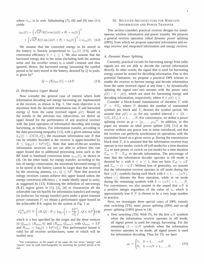
Fig. 6. Rate-energy tradeoff for TS vs. SPS based separated receiver withh = 1, P = 100, ζ = 1 andσ2
A = 1.
Next, we address the two special cases of DPS, i.e., the TSscheme and the SPS scheme. Substituting (15) into (19), theachievable R-E region for the TS scheme is given by
CTSR−E(P ) ,
⋃
α
{
(R,Q) : Q ≤ αζhP,
R ≤ (1− α) log2
(
1 +hP
σ2A + σ2
cov
)}
. (20)
Let Rmax = log2(
1 + hP/(σ2A + σ2
cov))
given in (4) andQmax = ζhP given in (13). It is noted that the boundary ofCTSR−E(P ) is simply a straight line connecting the two points
(Rmax, 0) and (0, Qmax) asα sweeps from 0 to 1.Substituting (16) into (19), the achievable R-E region for
the SPS scheme is given by
CSPSR−E(P ) ,
⋃
ρ
{
(R,Q) : Q ≤ ρζhP,
R ≤ log2
(
1 +(1 − ρ)hP
(1− ρ)σ2A + σ2
cov
)}
. (21)
Proposition 4.1: For the separated information and energyreceiver, the SPS scheme is the optimal DPS scheme, i.e.,CDPSR−E(P ) = CSPS
R−E(P ), P ≥ 0.Proof: Please refer to Appendix A.
From Proposition 4.1, it suffices for us to consider the SPSscheme for the optimal R-E tradeoff in the case of separatedreceivers. In particular, ifσ2
A ≪ σ2cov, i.e., the processing noise
is dominant over the antenna noise, from (18) the SNR at theinformation receiverτ(ρ) → (1 − ρ)hP/σ2
cov. In the otherextreme case withσ2
A ≫ σ2cov, from (18) we haveτ(ρ) →
hP/σ2A, which is independent ofρ. Thus, the optimal rate-
energy tradeoff is achieved when infinitesimally small poweris split to the information receiver, i.e.,ρ → 1. In this case, itcan be shown that whenζ = 1, CSPS
R−E(P ) → CUBR−E(P ), which
is the R-E tradeoff outer bound given in (14).Fig. 6 shows the achievable R-E regions under different
noise power setups for the separated information and energy
receiver (SepRx). It is assumed thath = 1, P = 100, ζ =1, and the antenna noise power is set to beσ2
A = 1. Withnormalization, for convenience we denote the information rateand harvested energy in terms of bits/channel use and energyunit, respectively. In Fig. 6, it is observed that for SepRx,the SPS scheme always achieves larger R-E pairs than theTS scheme for different values of the processing (RF bandto baseband conversion) noise powerσ2
cov. Moreover, asσ2cov
increases, the gap betweenCTSR−E(P ) and CSPS
R−E(P ) shrinks,while asσ2
cov decreases, the achievable R-E region with SPSenlarges and will eventually approach to the R-E region upperbound given in (14) whenσ2
cov → 0.
V. RATE-ENERGY TRADEOFF FORINTEGRATED
INFORMATION AND ENERGY RECEIVER
In this section, we study the rate-energy performance for theintegrated information and energy receiver shown in Fig. 5.Inthe integrated receiver, due to the RF to baseband conversionby the rectifier, we shall see that the equivalent basebandchannel is nonlinear, as opposed to that of the separatedreceiver where the channel is linear.
From (12), for convenience we re-expressiDC(t) as follows:
iDC(t) =∣
∣
∣
√hPA(t)ej(θ+φ(t)) + nA(t)
∣
∣
∣
2
+ nrec(t). (22)
Since planar rotation does not change the statistics ofnA(t),(22) can be equivalently written as
iDC(t) =∣
∣
∣
√hPA(t) + nA(t)
∣
∣
∣
2
+ nrec(t). (23)
As shown in Fig. 5, after the noiseless power splitter andADC, the outputy[k], k = 1, . . . , N , is given by
y[k] = (1− ρk)
(
∣
∣
∣
√hPA[k] + nA[k]
∣
∣
∣
2
+ nrec[k]
)
. (24)
In the above it is worth noting that the average SNR at anykis independent ofρk provided thatρk < 1. Thus, to minimizethe power split for information decoding (or maximize thepower split for energy harvesting), we should letρk → 1, ∀k,i.e., splitting infinitesimally small power to the informationreceiver all the time. Thereby, DPS becomes an equivalentSPS withρ → 1 in the case of integrated receiver.
With ρk ’s all equal to 1 in (24), the equivalent discrete-timememoryless channel for the information decoder is modeledas
Y =∣
∣
∣
√hPX + Z2
∣
∣
∣
2
+ Z1 (25)
whereX denotes the signal power, which is the nonnegativechannel input;Y denotes the channel output;Z2 ∼ CN (0, σ2
A)denotes the antenna noise; andZ1 ∼ N (0, σ2
rec) denotesthe rectifier noise. It is worth noting that for the channel(25) information is encoded in the power (amplitude) of thetransmitted signalx(t), rather than the phase ofx(t). Thechannel in (25) is nonlinear and thus it is challenging todetermine its capacityCNL and corresponding optimal inputdistribution subject toX ≥ 0 and E[X ] ≤ 1, whereX isreal. Similar to the case of separated receiver, we considerthefollowing two special noise power setups:

7
• Case 1 (Negligible Antenna Noise) withσ2A → 0: In
practice, this case may be applicable when the antennanoise power is much smaller than the rectifier noisepower, thus the antenna noise can be omitted. Withσ2A → 0, we haveZ2 → 0. Thus, the channel in (25)
becomesY = hPX + Z1 (26)
whereX ≥ 0 and real-valued, which is known as theoptical intensity channel. It is shown in [17] that theoptimal input distribution to this channel is discrete.According to [18], the capacityC1 for the channel (26)is upper-bounded by
Cub1 = log2
(
βe−
δ2
2σ2rec +
√2πσrecQ
(
δ
σrec
))
+
1
2Q(
δ
σrec
)
+1
β
δ + hP +σrece
−
δ2
2σ2rec√
2π
log2 e
+
δe−
δ2
2σ2rec
2√2πσrec
+δ2
2σ2rec
(
1−Q(
δ + hP
σrec
))
log2 e
− 1
2log2 2πeσ
2rec (27)
whereQ(·) = 1√2π
∫∞x
e−t2
2 dt denotes theQ-function,and β > 0, δ ≥ 0 are free parameters. The detailsof choice for β and δ are provided in [18], and thusare omitted in this paper for brevity. Moreover, theasymptotic capacity at high power (P → ∞) is givenby [18]
C∞1 = log2
hP
σrec+
1
2log2
e
2π. (28)
• Case 2 (Negligible Rectifier Noise) withσrec → 0: Thiscase is applicable when the antenna noise power is muchgreater than the rectifier noise power; thus, the rectifiernoise can be omitted. Withσrec → 0, we haveZ1 → 0.The channel in (25) is then simplified as
Y =∣
∣
∣
√hPX + Z2
∣
∣
∣
2
(29)
which is equivalent to thenoncoherent AWGN channel.It is shown in [19] that the optimal input distribution tothis channel is discrete and possesses an infinite numberof mass points. The capacityC2 for the channel (29) isupper-bounded by [19]
Cub2 =
1
2log2
(
1 +hP
σ2A
)
+1
2
(
log22π
e− CE log2 e
)
(30)whereCE is Euler’s constant. Moreover, the asymptoticcapacity at high power (P → ∞) is given by [19], [20]
C∞2 =
1
2log2
(
1 +hP
2σ2A
)
(31)
which is achieved by choosingX as central chi-squaredistribution with one degree of freedom4.
4In this case, the input amplitude is distributed as the positive normal
distribution, with probability density functionfA(a) =√
2πe−
a2
2 .
101
102
103
104
2
4
6
8
10
12
14
P
Rat
e (b
its/c
hann
el u
se)
C1ub
C2ub
CNLub
CNLlb
C1ub and C
NLub
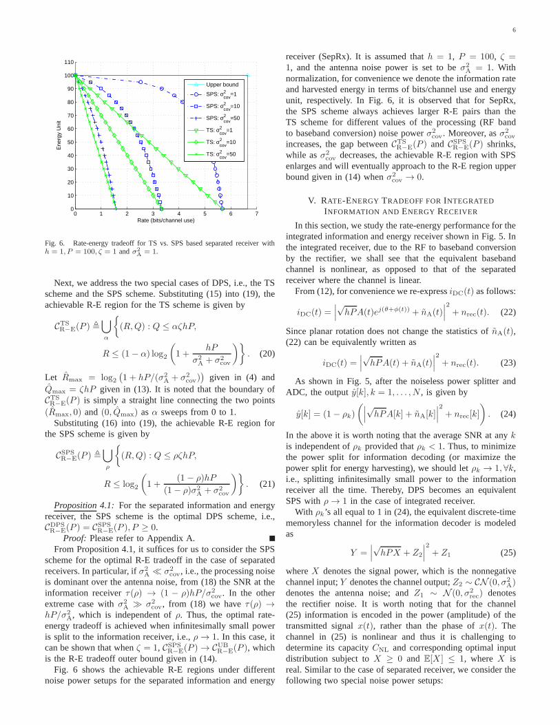
Fig. 7. Capacity bounds for the channels (25), (26) and (29) with h =1, σ2
A = 10−4 andσrec = 1.
In general, the capacityCNL of the channel given in (25)can be upper-bounded by
CubNL = min{Cub
1 , Cub2 } (32)
and the capacity lower boundC lbNL for the channel (25) can be
computed by the mutual information obtained from any inputdistribution satisfying the constraintX ≥ 0 andE[X ] ≤ 1. Itis worth noting that at high power (P → ∞) from (28) and(31), C∞
1 grows like log2 P ; while C∞2 grows like 1
2 log2 P .Thus the channel (29) provides a tighter upper bound for theasymptotic capacity of the channel (25) than the channel (26)at high SNR.
Fig. 7 shows the capacity bounds for the above three chan-nels (25), (26) and (29). It is assumed thath = 1, σ2
A = 10−4
andσrec = 1. The capacity lower boundC lbNL for the channel
given in (25) is computed by assuming the input (power)distribution is a central chi-square distribution with onedegreeof freedom. We shall use this lower bound as the achievablerate for the integrated receiver in the subsequent numericalresults. It is observed that in this case with dominant rectifiernoise, the capacity upper boundCub
1 in (27) is tighter thanCub
2 in (30). It is also observed that the gap between thecapacity upper and lower bounds, namelyCub
NL and C lbNL,
is still notably large under this setup, which can be furtherreduced by optimizing the input distribution.
To summarize, the achievable R-E region for the case ofintegrated receivers by SPS withρ → 1 is given by
CSPSR−E(P ) , {(R,Q) : R ≤ CNL(P ), Q ≤ ζhP} (33)
whereCNL(P ) denotes the capacity of the nonlinear (NL)channel given in (25) subject toX ≥ 0 andE[X ] ≤ 1.
Remark 5.1: We have characterized the rate-energy perfor-mance for the integrated receiver assuming an ideal ADC withzero quantization noise. Now we extend our results to thecase of nonzero quantization noisenADC(t). It is assumedthat nADC(t) ∼ N (0, σ2
ADC) for the integrated receiver [21],

8
[22]. With nonzero ADC noise, (24) is modified as
y[k] = (1− ρk)
(
∣
∣
∣
√hPA[k] + nA[k]
∣
∣
∣
2
+ nrec[k]
)
+ nADC[k]. (34)
Thus, for givenk the equivalent channel in (25) still holds,where Z1 ∼ N
(
0, σ2rec +
σ2ADC
(1−ρk)2
)
denotes the equivalentprocessing noise. It is worth noting that the equivalent pro-cessing noise power is a function of the power splitting ratioρk; thus, the capacity in channel (25) is also a function ofρk.The achievable R-E region for the integrated receiver by DPSis thus given by
CDPSR−E(P ) ,
⋃
ρ
{
(R,Q) : R ≤ 1
N
N∑
k=1
CNL(P, ρk),
Q ≤ 1
N
N∑
k=1
ρkζhP
}
. (35)
For the separated receiver, the results in Section IV can beeasily extended to the case with nonzero ADC noise by addingthe ADC noise power to the total processing noise power.
Figs. 8 and 9 show the achievable R-E regions under dif-ferent noise power setups for both cases of SepRx and IntRx.For both figures, it is assumed thath = 1, P = 100, ζ = 0.6,andσ2
A = 1. In Fig. 8, it is assumed thatσ2ADC = 0. In Fig.
9, it is assumed thatσ2ADC = 1, andρk = ρ, ∀k in (35) with
0 ≤ ρ ≤ 1. Note that in practice, the degradation of ADC noiseis usually modeled by a so-called signal-to-quantization-noiseratio (SQNR), approximately given by6K dB, whereK isthe number of quantization bits. Here, by assumingP = 100and σ2
ADC = 1, the SQNR equals to 20dB, which impliesK ≈ 3.3bits. It follows that the number of quantization levelsis approximately 10. In Figs. 8 and 9, the achievable ratesfor IntRx are computed as the capacity lower bound for thechannel given in (25) assuming the input as central chi-squaredistribution with one degree of freedom.
As shown in Fig. 8, the achievable R-E regions for IntRxwith zero ADC noise are marked by boxes as given in (33).In addition, when the processing noise power (σ2
cov for SepRxand σrec for IntRx) equals to the antenna noise power, i.e.,σ2A = σ2
cov = σrec = 1, the achievable rate for IntRx is notablylower than that for SepRx, due to the use of noncoherent(energy) modulation by IntRx as compared to the use ofcoherent modulation by SepRx. However, when the processingnoise power is much greater than the antenna noise power(as in most practical systems), the achievable R-E region ofIntRx becomes superior compared to that of SepRx with thesame processing noise power, i.e.,σ2
cov = σrec = 100. This isdue to the fact that for IntRx, the processing (rectifier) noiseincurs prior to the power splitter and thus only infinitesimallysmall power is required to be split by the power splitter toimplement the energy detection for information decoding (cf.(25)), while for SepRx, more power needs to be split to theinformation decoder to compensate for the processing (RFband to baseband conversion) noise that incurs after the powersplitter. Moreover, in Fig. 8 it is observed that IntRx is moresuitable than SepRx when more wireless power is desired.
0 1 2 3 4 5 60
10
20
30
40
50
60
70
Rate (bits/channel use)
Ene
rgy
Uni
t
SepRx: σ2cov
=1
SepRx: σ2cov
=100
IntRx: σrec
=1
IntRx: σrec
=100
Fig. 8. Rate-energy tradeoff for separated vs. integrated receivers withh =1, P = 100, ζ = 0.6, σ2
A = 1 andσ2ADC = 0.
0 1 2 3 4 5 60
10
20
30
40
50
60
70
Rate (bits/channel use)
Ene
rgy
Uni
t
SepRx:σ2cov
=1
SepRx:σ2cov
=100
IntRx:σrec
=1
IntRx:σrec
=100
Fig. 9. Rate-energy tradeoff for separated vs. integrated receivers withh =1, P = 100, ζ = 0.6 andσ2
A= σ2
ADC= 1.
In Fig. 9, it is observed that the achievable R-E regionsfor IntRx with nonzero ADC noise are no longer boxes.Comparing Fig. 9 with Fig. 8, it is observed that the achievablerate by IntRx with nonzero ADC noise is less than that byIntRx with zero ADC noise, especially when more harvestedenergy is desired.
VI. RATE-ENERGY TRADEOFF WITH RECEIVER CIRCUIT
POWER CONSUMPTION
In Sections IV and V, the harvested energy is character-ized as the energy harvested by the energy receiver withoutconsideration of power consumption by the receiver circuits.For energy receiver, there is no energy consumption since boththe Schottky diode and LPF are passive devices5. However, for
5In practice, some RF energy harvesting systems have additional controlcircuits which consume power, however, this power consumption has beenincluded in the conversion efficiencyζ.

9
information receiver, some amount of power will be consumedto supply the information decoding circuits. In particular, forthe separated receiver shown in Fig. 4, the circuit powerconsumed by information decoding, denoted byPS, is givenby PS = Pm+PADC, wherePm andPADC denote the powerconsumed by the RF band mixer and the ADC, respectively.For the integrated receiver shown in Fig. 5, however, the circuitpower consumed by information decoding, denoted byPI, isonly given by PI = PADC.6 Note that in generalPS willbe much greater thanPI, since the RF band mixer consumescomparable amount of power as compared to the ADC. Thusthenet energy stored in the battery will be the harvested energysubtracted by that consumed by information decoding circuits.In this section, we study the rate-energy tradeoff for bothseparated and integrated receivers with receiver circuit powerconsumption taken into account.
A. Separated Receiver with PS > 0
For the separated receiver shown in Fig. 4, by modifying(19) to account for the circuit powerPS, the achievable R-Eregion for the DPS scheme is given by
CDPS′
R−E (P ) ,⋃
ρ
(R,Q) : 0 ≤ Q ≤1
N
N∑
k=1
ρkζhP −
N∑
k=αN+1
PS
,
R ≤1
N
N∑
k=αN+1
log2
(
1 +(1 − ρk)hP
(1− ρk)σ2A+ σ2
cov
)
. (36)
Next, we address one special case of DPS, i.e., the OPSscheme. Substituting (17) into (36), the achievable R-E regionfor the OPS scheme is given by
COPS′
R−E (P ) ,⋃
α,ρ
{
(R,Q) : 0 ≤ Q ≤ αζhP + (1− α)ρζhP
−(1− α)PS, R ≤ (1 − α) log2
(
1 +(1 − ρ)hP
(1− ρ)σ2A + σ2
cov
)}
.
(37)
Proposition 6.1: For the separated information and energyreceiver withPS > 0, the OPS scheme is the optimal DPSscheme, i.e.,CDPS′
R−E (P ) = COPS′
R−E (P ), P ≥ 0.Proof: Please refer to Appendix B.
From Proposition 6.1, it suffices to consider the OPS schemefor the optimal R-E tradeoff in the case of separated receivers.Unlike the case ofPS = 0, where the boundary ofCDPS
R−E =CSPSR−E is achieved asρ sweeps from 0 to 1, the optimal power
splitting pairs(α∗, ρ∗) that achieve the boundary ofCDPS′
R−E =
COPS′
R−E has to be determined. We thus consider the followingoptimization problem:
(P0) : max.α,ρ
R = (1− α) log2
(
1 +(1− ρ)hP
(1− ρ)σ2A + σ2
cov
)
s.t. αζhP + (1− α)ρζhP − (1− α)PS ≥ Q,
0 ≤ α ≤ 1, 0 ≤ ρ ≤ 1,
6Here PS and PI are defined according to the proposed architectures inFig. 4 and Fig. 5, respectively. In practice, the information decoding circuitsmay contain additional components, such as a low noise amplifier (LNA)in the separated receiver. In general, the power consumed bythe additionalcomponents can be added toPS or PI.
Problem (P0) is feasible if and only ifQ ≤ ζhP . It iseasy to verify that(R,Q) = (0, ζhP ) is achieved byα = 1.Next, we consider Problem (P0) for givenQ ∈ [0, ζhP ) and0 ≤ α < 1. The optimal solution of (P0) is obtained with thefirst constraint strictly equal, otherwise we can always decreaseα or ρ to obtain a larger rateR. Thus the boundary points(R,Q) satisfy the following two equations,
Q = αζhP + (1− α)ρζhP − (1− α)PS, (38)
R = (1− α) log2
(
1 +(1− ρ)hP
(1 − ρ)σ2A + σ2
cov
)
. (39)
From (38), we have
ρ =Q− αζhP + (1− α)PS
(1− α)ζhP. (40)
From (40), we haveα ∈[
max{Q+PS−ζhPPS
, 0}, Q+PS
ζhP+PS
]
suchthat 0 ≤ ρ ≤ 1. Substituting (40) to (39), we have
R = (1− α) log2
(
1 +
ζhP−Q−(1−α)PS
ζ
ζhP−Q−(1−α)PS
ζhPσ2A + σ2
cov(1− α)
)
.
(41)
From (41),R is a function ofα with fixedQ. For convenience,we rewrite (41) as follows:
R(s) = s log2
(
1 +cs+ d
as+ b
)
(42)
wheres = 1 − α, a = σ2cov − σ2
APS
ζhP, b = σ2
A
(
1− QζhP
)
>
0, c = −PS
ζ< 0 and d = hP
(
1− QζhP
)
> 0.
It is worth noting that s ∈[
ζhP−QζhP+PS
,min{ ζhP−QPS
, 1}]
,
or equivalently, s ∈[
dhP−c
,min{− dc, 1}]
, since α ∈[
max{Q+PS−ζhPPS
, 0}, Q+PS
ζhP+PS
]
. The following lemma de-
scribes the behavior ofR(s) in terms ofs, which is importantfor determining the boundary points(R,Q).
Lemma 6.1: With Q ∈ [0, ζhP ), R(s) is concave ins ∈[ dhP−c
,min {− dc, 1}].
Proof: Please refer to Appendix C.By Lemma 6.1, the optimals∗ ∈ [ d
hP−c,min {− d
c, 1}] that
maximizesR(s) can be efficiently obtained by searching overs ∈ [ d
hP−c,min {− d
c, 1}] using the bisection method. The
optimal α∗ is thus given byα∗ = 1 − s∗. The optimalρ∗ isgiven by (40) withα = α∗. The correspondingR is given by(39) with α = α∗ andρ = ρ∗. To summarize, each boundarypoint (R,Q) of COPS′
R−E is achieved by a unique power splittingpair (α∗, ρ∗).
Fig. 10 shows the achievable R-E regions (labeled as “netenergy”) for SepRx with receiver circuit power consumption.The total harvested energy (labeled as “total energy”), includ-ing both the net energy stored in the battery and the energyconsumed by information decoding, is also shown in Fig. 10as a reference. For SepRx withPS = 25, it is observedthat CTS′
R−E ⊆ COPS′
R−E and CSPS′
R−E ⊆ COPS′
R−E . Moreover, SPSachieves the RE-region boundary only at low harvested energyregion, whereCSPS′
R−E and COPS′
R−E partially coincide. However,the performance of SPS becomes worse (even worse than TS)

10
0 0.5 1 1.5 2 2.5 30
10
20
30
40
50
60
Rate (bits/channel use)
Ene
rgy
Uni
t
TS: total energyTS: net energySPS: total energySPS: net energyOPS: total energyOPS: net energy
Fig. 10. Rate-energy tradeoff for the separated receiver with receiver circuitpower consumption. It is assumed thath = 1, P = 100, ζ = 0.6, σ2
A =1, σ2
cov = 10 andPS = 25.
when more harvested energy is desired, since it is unwiseand energy-inefficient to keep information receiver alwaysonduring the whole transmission time.
B. Integrated Receiver with PI > 0
For the integrated receiver, the achievable R-E region forthe DPS scheme taking into account circuit powerPI is givenby
CDPS′
R−E (P ) ,⋃
ρ
{
(R,Q) :0 ≤ Q ≤1
N
N∑
k=1
ρkζhP −
N∑
k=αN+1
PI
,
R ≤1
N
N∑
k=αN+1
CNL
. (43)
SinceR is independent ofρk, we should setρk → 1 for allk = αN+1, . . . , N . Thus, the OPS scheme withρ → 1 is theoptimal DPS scheme for the integrated receiver withPI > 0.Then (43) can be simplified as
COPS′
R−E (P ) ,⋃
α
{(R,Q) :0 ≤ Q ≤ ζhP − (1− α)PI,
R ≤ (1− α)CNL} . (44)
Note that whenPI < ζhP , the boundary ofCOPS′
R−E (P ) isdetermined by two lines asα sweeps from 0 to 1, withone vertical line connecting the two points(CNL, 0) and(CNL, ζhP − PI), and another line connecting the two points(CNL, ζhP − PI) and (0, ζhP ). While PI ≥ ζhP , theboundary ofCOPS′
R−E (P ) is simply a straight line connectingthe two points(ζhPCNL/PI, 0) and (0, ζhP ) as α sweepsfrom 1− ζhP/PI to 1.
Fig. 11 shows the achievable R-E regions for both casesof SepRx and IntRx with receiver circuit power consumption.We consider two setups for the receiver circuit power con-sumption, i.e., low circuit power withPS = 25, PI = 10,and high circuit power withPS = 200, PI = 80. For the
0 1 2 3 4 5 60
10
20
30
40
50
60
Rate (bits/channel use)
Ene
rgy
Uni
t
SepRx: PS=25
IntRx: PI=10
SepRx: PS=200
IntRx: PI=80
Fig. 11. Rate-energy tradeoff for separated vs. integratedreceivers withreceiver circuit power consumption. It is assumed thath = 1, P = 100, ζ =0.6, σ2
A = 0.01, σ2cov = 1 andσrec = 10.
low circuit power withPS = 25, PI = 10, IntRx is superiorover SepRx when more harvested energy is desired, whileSepRx is superior when less harvested energy (no greaterthan 37 energy units) is required. For the high circuit powerwith PS = 200, PI = 80, IntRx is always superior overSepRx, since for SepRx much more transmission time needsto be allocated for harvesting energy to compensate the powerconsumed by information decoding.
VII. PRACTICAL MODULATION
In this section, we study the performances for the twotypes of receivers under a realistic system setup that employspractical modulation. Let the signal set (constellation) bedenoted byX . The size ofX is denoted byM with M = 2l,and l ≥ 1 being an integer. It is assumed that the maximumrate that the practical modulation can support isl ≤ 10bits/channel use. Thei-th constellation point inX is denotedby xi, i = 1, . . . ,M , with equal probabilitypX(xi) = 1/Mfor simplicity. For the separated receiver, we assume thatcoherentM -ary quadrature amplitude modulation (QAM) isutilized for transmission. The symbol error rate (SER), denotedby PQAM
s , is approximated by [23]
PQAMs ≈ 4(
√M − 1)√M
Q(
√
3τsM − 1
)
(45)
whereτs denotes the average SNR per symbol at the informa-tion receiver7. The approximation is tight at high SNR, and istaken to be exact for simplicity in the sequel. For the integratedreceiver, as mentioned earlier in Section V, information isencoded by the energy (power) of the transmitted signal.Similar to the pulse amplitude modulation (PAM), we assumethe pulse energy modulation (PEM), with equispacedpositive
7Binary phase shift keying (BPSK) is used whenl = 1. For simplicity, weuse (45) to approximate the SER of BPSK at high SNR.

11
constellation points given by
xi =2(i− 1)
M − 1, i = 1, . . . ,M. (46)
A closed-form expression for the symbol error ratePPEMs
appears intractable, due to the coupled antenna and rectifiernoise for the channel (25). For most practical systems, therectifier noise power will be much greater than the antennanoise power, while the antenna noise is approximately atthe thermal noise level. This justifies the assumption thatσ2A ≪ σrec and we thus approximate the channel (25) with
(26). For simplicity, the decision boundary is chosen as theperpendicular bisector of each pair of adjacent two points,and the symbol error rate can be derived to be
PPEMs =
2(M − 1)
MQ(
τ ′sM − 1
)
(47)
whereτ ′s = hP/σrec is defined as the average SNR per symbolat the information receiver.
For both separated and integrated receivers, we assumethe transmitter can adapt the transmission rate such that thesymbol error rate is less than a target valueP tgt
s , i.e.,PQAMs ≤
P tgts and PPEM
s ≤ P tgts for the separated and integrated
receivers, respectively. Moreover, we assume that there isa minimum net harvested energy requirementQreq at thereceiver side, i.e.,Q ≥ Qreq, where0 ≤ Qreq ≤ ζhP . Withthe SER constraint and minimum harvested energy constraint,our objective is to achieve the maximum rate. For the separatedreceiver with OPS scheme, the maximum achievable rate canbe obtained by
(P1) :
max.α,ρ,M
R = (1− α) log2 M
s.t.4(√M − 1)√M
Q(√
3
M − 1· (1− ρ)hP
(1− ρ)σ2A + σ2
cov
)
≤ Ptgts ,
(48)
αζhP + (1− α)ρζhP − (1− α)PS ≥ Qreq, (49)
0 ≤ α ≤ 1, 0 ≤ ρ ≤ 1,
M = 2l, l ∈ {1, 2, . . . , 10}
Here, the optimization variables are the power splitting pair(α, ρ) and the modulation sizeM .
For the integrated receiver with OPS scheme, the maximumachievable rate can be obtained by
(P2) : max.α,M
R = (1− α) log2 M
s.t.2(M − 1)
MQ(
1
M − 1· hP
σrec
)
≤ P tgts , (50)
ζhP − (1− α)PI ≥ Qreq,
0 ≤ α ≤ 1,
M = 2l, l ∈ {1, 2, . . . , 10}Note that here the optimization variables only includeα andM , since the OPS scheme withρ → 1 is optimal for theintegrated receiver (c.f. Section VI).
We denote the maximum rate for (P1) and (P2) asR∗1
andR∗2, respectively. Similarly, the optimal variables for (P1)
0 0.5 1 1.5
10−2
10−1
100
101
102
log10
d
Rat
e (M
bps)
SepRxIntRx
Fig. 12. Maximum achievable rate for separated and integrated receiversover different transmission distance.
and (P2) are denoted with corresponding superscripts andsubscripts, e.g.,α∗
1, ρ∗1, etc. With 0 ≤ Qreq ≤ ζhP and
reasonable SNR (such that the SER constraints can be satisfiedby someM ), the optimal solution for (P1) is obtained byan exhaustive search forρ∗1: for each fixedρ1 ∈ [0, 1), we
haveR∗1 = (1−α∗
1) log2 M∗1 , whereα∗
1 =[
Qreq−ρ1ζhP+PS
(1−ρ1)ζhP+PS
]+
andM∗1 attains the maximum value under the SER constraint
(48); the optimalρ∗1 is then obtained to maximizeR∗1. The
optimal solution for (P2) is given byR∗2 = (1−α∗
2) log2 M∗2 ,
whereα∗2 =
[
Qreq−ζhP+PI
PI
]+
andM∗2 is maximized under the
SER constraint (50). For both (P1) and (P2), the achievablerateR is determined by both the modulation sizeM and thetime percentageα that the information decoder operates inthe off mode. Moreover, as the received signal powerhPdecreases,M decreases to satisfy the modulation constraintandα increases to satisfy the harvested energy constraint, bothof which result in a decrease of the achievable rate.
Typically for practical systems we havePS > PI > 0, sincethe RF band mixer in the separated receiver will consumeadditional circuit power. Henceforth, we assumePS > PI > 0.
Proposition 7.1: For separated and integrated receivers with0 ≤ Qreq ≤ ζhP and PS ≥ PI > 0, we haveα∗
1 ≥ α∗2.
Moreover, if M∗1 ≤ M∗
2 , then the maximum achievable rateby the separated receiver will be no greater than that by theintegrated receiver, i.e.,R∗
1 ≤ R∗2.
Proof: Please refer to Appendix D.Most practical systems of interest typically operate at the
high SNR regime for the information receiver, due to the high-power operating requirement for the energy receiver. Thus,forsufficiently small transmission distance, it is expected that bothreceivers can support the maximum modulation size under theSER constraint, i.e.,M∗
1 = M∗2 = 210. Thus, by Proposition
7.1, the integrated receiver outperforms the separated receiverfor sufficiently small transmission distance.
Fig. 12 shows an example of the maximum achievable rate

12
for a practical point-to-point wireless system with separated orintegrated receiver. The corresponding modulation sizeM andtime percentageα are shown in Fig. 13. The transmitter poweris assumed to beP = 1 watt(W) or30dBm. The distance fromthe transmitter to the receiver is assumed to bed meters withd ≥ 1, which results in approximately(−30− 30 log10 d)dBof signal power attenuation at a carrier frequency assumed asfc = 900MHz. The bandwidth of the transmitted signal isassumed to be10MHz. For information receiver, the antennanoise temperature is assumed to be290K, which correspondsto σ2
A = −104dBm over the bandwidth of10MHz. As in mostpractical wireless communication systems, it is assumed thatthe processing noise power is much greater than the antennanoise power, in which case the antenna noise can be omitted.In particular, it is assumed thatσ2
cov = −70dBm for theseparated receiver [24] andσrec = −50dBm for the integratedreceiver. The circuit power consumed by information decodingis assumed to bePS = 0.5mW for the separated receiver, andPI = 0.2mW for the integrated receiver. For energy receiver,the energy conversion efficiency is assumed to beζ = 60%.The minimum harvested energy requirementQreq is set tobe zero, which is the minimum requirement for a zero-net-energy system that does not need external power source, i.e.,the receiver is “self-sustainable”. The symbol error rate targetis assumed to beP tgt
s = 10−5.In Fig. 12, it is observed that when0 ≤ log10 d ≤ 1, IntRx
achieves more rate than SepRx. By Proposition 7.1, IntRxoutperforms SepRx over the range0 ≤ log10 d ≤ 0.4 withM∗
1 = M∗2 = 210; however, Proposition 7.1 provides only a
sufficient condition, numerical results show that IntRx outper-forms SepRx over longer distances up tolog10 d ≤ 1. Thisis due to the fact that although SepRx supports higher-orderconstellations (largerM ) than IntRx when0.4 < log10 d ≤ 1,the information receiver of SepRx needs to operate in theoff mode for more time (largerα) to compensate the powerconsumed by information decoding (c.f. Fig. 13). It turnsout that over this range, the average rate over the wholetransmission time of SepRx is less than that achieved byIntRx. As log10 d increases, the rate gap between SepRx andIntRx shrinks and converges whenlog10 d is around 1. When1.1 ≤ log10 d ≤ 1.5, SepRx achieves more rate than IntRx,sinceα for both receivers approaches to 1 (c.f. Fig. 13), whilethe achievable rates are dominated by the modulation size (M ,c.f. Fig. 13). Note that whenlog10 d = 1.5, no modulation cansupport IntRx due to the extremely low received SNR; how-ever, SepRx can still achieve some positive rate. In addition,Fig. 13 shows that in general IntRx exploits lower complexity(smallerM ) in generating signal constellation.
VIII. C ONCLUSION
This paper investigates practical receiver designs for si-multaneous wireless information and power transfer. Basedon dynamic power splitting (DPS), we propose two practi-cal receiver architectures, namely,separated and integratedinformation and energy receivers. For the separated receiver,the received signal by the antenna is split into two signalstreams in the RF band, which are then separately fed to
0 0.5 1 1.51
2
3
4
5
6
7
8
9
10
log10
d
log 2 M
SepRxIntRx
0 0.5 1 1.50
0.1
0.2
0.3
0.4
0.5
0.6
0.7
0.8
0.9
1
log10
d
α
SepRxIntRx
Fig. 13. Optimal modulation size (M ) and information receiver off-timepercentage (α) for separated and integrated receivers.
the conventional energy receiver and information receiverfor harvesting energy and decoding information, respectively.For the integrated receiver, part of the information decod-ing implementation, i.e., the RF to baseband conversion, isintegrated to the energy receiver via the rectifier. For bothreceivers, we characterize the rate-energy performance takingcircuit power consumption into account. Numerical resultsshow that when the circuit power consumptions are small(compared with the received signal power), the separatedreceiver is superior at low harvested energy region; whereasthe integrated receiver performs better at high harvested energyregion. When the circuit power consumptions are large, theintegrated receiver is superior. Moreover, the performance forthe two types of receivers is studied under a realistic systemsetup that employs practical modulation. With symbol errorrate constraint and minimum harvested energy constraint, themaximum achievable rates by the two types of receivers arecompared. It is shown that for a system with zero-net-energyconsumption, the integrated receiver achieves more rate thanseparated receiver at small transmission distances.
13
APPENDIX APROOF OFPROPOSITION4.1
To show CDPSR−E(P ) = CSPS
R−E(P ), P ≥ 0, it sufficesfor us to show thatCSPS
R−E(P ) ⊆ CDPSR−E(P ), P ≥ 0 and
CDPSR−E(P ) ⊆ CSPS
R−E(P ), P ≥ 0. The first part of proof istrivial, since SPS is just a special case of DPS by lettingρk = ρ, ∀k (c.f. (16)). Next, we prove the second part.Assuming thatf(ρ) = log2
(
1 + (1−ρ)hP(1−ρ)σ2
A+σ2
cov
)
, it is easy
to verify that f(ρ) is concave inρ ∈ [0, 1]. By Jensen’s
inequality, we have1N
N∑
k=1
f(ρk) ≤ f
(
1N
N∑
k=1
ρk
)
. Thus, for
∀ρ = [ρ1, . . . , ρN ]T , ∃ρ = 1N
N∑
k=1
ρk, so that 1N
N∑
k=1
ρkζhP =
ρζhP and 1N
N∑
k=1
f(ρk) ≤ f(ρ). Since R-E region is defined
as the union of rate-energy pairs(R,Q) under all possibleρ, it follows immediately thatCDPS
R−E(P ) ⊆ CSPSR−E(P ), P ≥ 0,
which completes the proof of Proposition 4.1.
APPENDIX BPROOF OFPROPOSITION6.1
To show CDPS′
R−E (P ) = COPS′
R−E (P ), P ≥ 0, it sufficesfor us to show thatCOPS′
R−E (P ) ⊆ CDPS′
R−E (P ), P ≥ 0 andCDPS′
R−E (P ) ⊆ COPS′
R−E (P ), P ≥ 0. The first part of proof istrivial, since OPS is just a special case of DPS by lettingρk = ρ, k = αN, . . . , N (c.f. (17)). Next, we prove the secondpart. By (36),ρk ’s are optimized atρk = 1 for k = 1, . . . , αN ;
thus, we haveQ ≤ αζhP + 1N
N∑
k=αN+1
ρkζhP − (1 − α)PS
for DPS. For any givenα, by Jensen’s inequality we have
1(1−α)N
N∑
k=αN+1
f(ρk) ≤ f
(
1(1−α)N
N∑
k=αN+1
ρk
)
. Thus, for
∀α and∀ρ = [ρ1, . . . , ρN ]T , ∃ρ = 1(1−α)N
N∑
k=αN+1
ρk, so that
1N
N∑
k=αN+1
ρkζhP = (1 − α)ρζhP and 1N
N∑
k=αN+1
f(ρk) ≤(1 − α)f(ρ). Since R-E region is defined as the union ofrate-energy pairs(R,Q) under all possibleρ, it followsimmediately thatCDPS′
R−E (P ) ⊆ COPS′
R−E (P ), P ≥ 0, whichcompletes the proof of Proposition 6.1.
APPENDIX CPROOF OFLEMMA 6.1
From (42), the first and second derivatives ofR(s) withrespect ofs are given by
dR
ds= log2
(
1 +cs+ d
as+ b
)
+s(bc− ad)
((a+ c)s+ b+ d) (as+ b) ln 2,
(51)d2R
ds2=
(bc− ad) ((b(a+ c) + a(d+ d)) s+ 2b(d+ d))
((a+ c)s+ b+ d)2(as+ b)2 ln 2
.
(52)From (52), the sign of d
2Rds2
is identical with the linef2(s) = (bc−ad) ((b(a+ c) + a(d+ d)) s+ 2b(d+ d)). Notethat bc − ad = −σ2
cov(hP − Q/ζ) < 0, f2(0) = 2b(b +
d)(bc − ad) < 0, and f2(− dc) = (2b+d)(bc−ad)2
c< 0;
thus, we haved2Rds2
< 0 for s ∈ [0,− dc]. Since the set
[ dhP−c
,min {− dc, 1}] is a subset of the set[0,− d
c], we have
d2Rds2
< 0 for s ∈ [ dhP−c
,min {− dc, 1}]. Thus,R(s) is concave
in s ∈ [ dhP−c
,min {− dc, 1}], which completes the proof of
Lemma 6.1.
APPENDIX DPROOF OFPROPOSITION7.1
We first consider (P1) with0 ≤ Qreq ≤ ζhP for theseparated receiver. The optimalα for (P1) is given byα∗
1 =[
Qreq−ρ∗
1ζhP+PS
(1−ρ∗
1)ζhP+PS
]+
. SinceQreq ≤ ζhP , α∗1 decreases asρ∗1
increases. Thus, we have
α∗1 ≥ Qreq − ρ∗1ζhP + PS
(1− ρ∗1)ζhP + PS
∣
∣
∣
ρ∗
1=1
=Qreq − ζhP + PS
PS. (53)
Next, for the integrated receiver with0 ≤ Qreq ≤ ζhP , theoptimalα for (P2) is given by
α∗2 =
[
Qreq − ζhP + PI
PI
]+
(54)
From (53) and (54), we haveα∗1 ≥ α∗
2, given thatPS > PI.SinceR = (1 − α) log2 M , we haveR∗
1 ≤ R∗2, given that
α∗1 ≥ α∗
2 andM∗1 ≤ M∗
2 . The proof of Proposition 7.1 thusfollows.
REFERENCES
[1] L. R. Varshney, “Transporting information and energy simultaneously,”in Proc. IEEE Int. Symp. Inf. Theory (ISIT), pp. 1612-1616, July 2008.
[2] P. Grover and A. Sahai, “Shannon meets Tesla: wireless information andpower transfer,” inProc. IEEE Int. Symp. Inf. Theory (ISIT), pp. 2363-2367, June 2010.
[3] L. Liu, R. Zhang, and K. C. Chua, “Wireless information transfer withopportunistic energy harvesting,”IEEE Trans. Wireless Commun., vol. 12,no. 1, pp. 288-300, Jan. 2013.
[4] R. Zhang and C. K. Ho, “MIMO broadcasting for simultaneous wirelessinformation and power transfer,”IEEE Trans. Wireless Commun., vol. 12,no. 5, pp. 1989-2001, May 2013.
[5] Z. Xiang and M. Tao, “Robust beamforming for wireless information andpower transmission,”IEEE Wireless Commun. Letters, vol. 1, no. 4, pp.372-375, 2012.
[6] B. K. Chalise, Y. D. Zhang, and M. G. Amin, “Energy harvesting in anOSTBC based amplify-and-forward MIMO relay system,” inProc. IEEEICASSP, pp. 3201-3204, Mar. 2012.
[7] A. M. Fouladgar and O. Simeone, “On the transfer of information andenergy in multi-user systems,”IEEE Commun. Letters, vol. 16, no. 11,pp. 1733-1736, Nov. 2012.
[8] K. Huang and V. K. N. Lau, “Enabling wireless power transfer in cellularnetworks: architecture, modeling and deployment,” available on-line atarXiv:1207.5640.
[9] S. Lee, R. Zhang, and K. Huang, “Opportunistic wireless energy har-vesting in cognitive radio networks,” to appear inIEEE Trans. WirelessCommun., available on-line at arXiv:1302.4793.
[10] Y. Wu, Y. Liu, Q. Xue, S. Li, and C. Yu,“Analytical designmethod ofmultiway dual-band planar power dividers with arbitrary power division,”IEEE Trans. Microwave Theory and Techniques, vol. 58, no. 12, pp. 3832-3841, Dec 2010.
[11] Product Datasheet, 11667A Power Splitter, Agilent Technologies.[12] T. Cover and J. Thomas,Elements of information theory, New York:
Wiley, 1991.[13] T. Paing, J. Shin, R. Zane, and Z. Popovic, “Resistor emulation approach
to low-power RF energy harvesting,”IEEE Trans. Power Electronics, vol.23, no. 3, pp. 1494-1501, May 2008.
[14] J. A. G. Akkermans, M. C. van Beurden, G. J. N. Doodeman, andH. J. Visser, “Analytical models for low-power rectenna design,” IEEEAntennas Wireless Propag. Letters, vol. 4, pp. 187-190, 2005.
[15] Product Datasheet, P2110-915MHz RF Powerharvester Receiver, Pow-ercast Corporation.

14
[16] H. Urkowitz, “Energy detection of unknown deterministic signals,”Proc.IEEE, vol. 55, pp. 523-231, Apr. 1967.
[17] I. Abou-Faycal and J. Fahs, “On the capacity of some deterministic non-linear channels subject to additive white Gaussian noise,”in Proc. IEEEInt. Conf. on Telecommunications (ICT), pp. 63-70, Apr. 2010.
[18] A. Lapidoth, S. M. Moser, and M. A. Wigger, “On the capacity of free-space optical intensity channels,”IEEE Trans. Inf. Theory, vol. 55, no.10, pp. 4449-4461, Oct. 2009.
[19] M. Katz and S. Shamai (Shitz), “On the capacity-achieving distributionof the discrete-time noncoherent and partially coherent AWGN channels,”IEEE Trans. Inf. Theory, vol. 50, no. 10, pp. 2257-2270, Oct. 2004.
[20] A. Lapidoth, “On phase noise channels at high SNR,” inProc. IEEEInf. Theory Workshop (ITW), Oct. 2002.
[21] P. Carbone and D. Petri,“Noise sensitivity of the ADC histogram test,”IEEE Trans. Instrum. Meas., vol. 47, no. 4, pp. 1001-1004, Aug. 1998.
[22] S. Ruscak and L. Singer, “Using histogram techniques tomeasure A/Dconverter noise,”Analog Dialogue, vol. 29, no. 2, 1995.
[23] A. Goldsmith, Wireless communications, Cambridge University Press,2005.
[24] M. Loy, “Understanding and enhancing sensitivity in receivers forwireless applications,” Technical brief SWRA030, Texas Instruments,available online at http://www.ti.com/lit/an/swra030/swra030.pdf