wie in de zorg werkt, verzekert zich bij izz
TRANSCRIPT
Recent experiments in trapped-ion quantum information. processing at NIST
J. Chiaverini, M. D. Barrett, R. B. Blakestad, J. Britton, W. Itano, J. D. Jost,E. Knill, C. Langer, D. Leibfried, R. Ozeri, T. Schaetz, and D. J. Wineland
National Institute of Standards and Technology, Boulder, Colorado 80305, USA
ABSTRACTAtomic ions confined in segmented trap arrays provide a system for quantum information processing. Wereport on the execution of two simple quantum algorithms, quantum error correction and the quantum Fouriertransform, using this implementation. The demonstration of these algorithms in a scalable system is one steptowards the execution of useful, large-scale quantum algorithms.
Keywords: Atomic physics, Quantum algorithms, Quantum communication, Quantum computing, Quantumerror correction, Quantum Fourier transform, Quantum information processing, Iapped ions
1. INTRODUCTIONQ uantum information processing (QIP) will enable great efficiency gains in certain tasks, such as the factorizationof large composite numbers,' when compared to classical information processing. The desired implementationof quantum algorithms in physical systems has spurred much experimental work examining candidate systems.Individual atomic ions confined in an electromagnetic trap and addressed with laser beams2 show particularpromise as a scalable system for QIP. The ions' internal hyperfine states have long coherence times36 and henceare useful as the system's qubits (quantum two-level systems), while the coupled motion of the ions in the trapprovides a means to perform multi-qubit entangling 78 Manipulation of the ions' quantum states isperformed by means of laser pulses, and ions can be shuttled between zones of a trap-array structure separatelyor in groups, providing one method for interaction of qubits in different parts of the array.9' 10
At NIST, we use such a system to perform simple quantum algorithms with a few ions. A key strengthof the trapped-ion approach is the ability to perform operations on a subset of the qubits dependent uponmeasurement outcomes of other qubits in real time, before the quantum information succumbs to decoherence.Here we describe the physical implementation of our ion quantum processor, including methods of manipulationof quantum information and the apparatus used to control the ion qubits. We report on the execution of aquantum-error-correcting protocol, a requirement for any implementation of large-scale QIP, and we will alsodescribe the demonstration of the semiclassical Fourier transform in our scalable system. The latter algorithmis a key step in Shor's quantum factoring algorithm,' one of the most anticipated of the quantum protocolscurrently proposed.
2. COHERENT QUBIT MANIPULATIONIn the experiments, we use 9Be+ ions confined to the axis of a multizone linear radio frequency Paul trap. Thequbits comprise the electronic ground-state hyperfine levels F =1, mF = —1) and F = 2, mF = —2) (denotedas 1) or 0) and ) or 1) respectively, by analogy to the states of a spin-i particle). The qubit levels areseparated in frequency by approximately 1.28 GHz.
Measurement is accomplished through projection of the state of each qubit using state-dependent resonancefluorescence (an ion in the ) state fluoresces, while an ion in the 1) state does not). Individual ion detectionscan be performed separately." 12
Further author information: (Send correspondence to J.C.)J.C.: E-mail: john.chiaverini©boulder.nist.govM.D.B.: Current address: Physics Department, University of Otago, Dunedin, New ZealandT.S.: Current address: MaxPlanck Institut für Quantenoptik, Garching, Germany
Recent experiments in trapped-ion quantum information. processing at NIST
J. Chiaverini, M. D. Barrett, R. B. Blakestad, J. Britton, W. Itano, J. D. Jost,E. Knill, C. Langer, D. Leibfried, R. Ozeri, T. Schaetz, and D. J. Wineland
National Institute of Standards and Technology, Boulder, Colorado 80305, USA
ABSTRACTAtomic ions confined in segmented trap arrays provide a system for quantum information processing. Wereport on the execution of two simple quantum algorithms, quantum error correction and the quantum Fouriertransform, using this implementation. The demonstration of these algorithms in a scalable system is one steptowards the execution of useful, large-scale quantum algorithms.
Keywords: Atomic physics, Quantum algorithms, Quantum communication, Quantum computing, Quantumerror correction, Quantum Fourier transform, Quantum information processing, Iapped ions
1. INTRODUCTIONQ uantum information processing (QIP) will enable great efficiency gains in certain tasks, such as the factorizationof large composite numbers,1 when compared to classical information processing. The desired implementationof quantum algorithms in physical systems has spurred much experimental work examining candidate systems.Individual atomic ions confined in an electromagnetic trap and addressed with laser beams2 show particularpromise as a scalable system for QIP. The ions' internal hyperfine states have long coherence times36 and henceare useful as the system's qubits (quantum two-level systems) ,while the coupled motion of the ions in the trapprovides a means to perform multi-qubit entangling Manipulation of the ions' quantum states isperformed by means of laser pulses, and ions can be shuttled between zones of a trap-array structure separatelyor in groups, providing one method for interaction of qubits in different parts of the 910
At NIST, we use such a system to perform simple quantum algorithms with a few ions. A key strengthof the trapped-ion approach is the ability to perform operations on a subset of the qubits dependent uponmeasurement outcomes of other qubits in real time, before the quantum information succumbs to decoherence.Here we describe the physical implementation of our ion quantum processor, including methods of manipulationof quantum information and the apparatus used to control the ion qubits. We report on the execution of aquantum-error-correcting protocol, a requirement for any implementation of large-scale QIP, and we will alsodescribe the demonstration of the semiclassical Fourier transform in our scalable system. The latter algorithmis a key step in Shor's quantum factoring algorithm,' one of the most anticipated of the quantum protocolscurrently proposed.
2. COHERENT QUBIT MANIPULATIONIn the experiments, we use 9Be+ ions confined to the axis of a multizone linear radio frequency Paul trap. Thequbits comprise the electronic ground-state hyperfine levels F =1, mF = —1) and F = 2, mF = —2) (denotedas 1) or 0) and ) or 1) respectively, by analogy to the states of a spin-i particle). The qubit levels areseparated in frequency by approximately 1.28 GHz.
Measurement is accomplished through projection of the state of each qubit using state-dependent resonancefluorescence (an ion in the ) state fluoresces, while an ion in the 1) state does not). Individual ion detectionscan be performed separately." 12
Further author information: (Send correspondence to J.C.)J.C.: E-mail: john.chiaverini©boulder.nist.govM.D.B.: Current address: Physics Department, University of Otago, Dunedin, New ZealandT.S.: Current address: Max Planck Institut für Quantenoptik, Garching, Germany
ICONO 2005: Ultrafast Phenomena and Physics of Superintense Laser Fields;Quantum and Atom Optics; Engineering of Quantum Information, edited by Hans A. Bachor et al,
Proc. of SPIE Vol. 6256, 625610, (2006) · 0277-786X/06/$15 · doi: 10.1117/12.682633
Proc. of SPIE Vol. 6256 625610-1

2.1. Single-qubit rotationsRotations corresponding to the operator R(9, çb) = cos(9/2) I — isin(9/2) cos o — i sin(9/2) sin çb o,, , arerealized with two-photon stimulated-Raman 913 14 implemented by two laser beams having a relativefrequency detuning equal to the qubit transition frequency. Here o- and a, are the usual Pauli operators, I isthe identity operator, 9 is the rotation angle, and çb is the angle of the rotation axis in the x-y plane. Rotationsaround an axis A by an angle will be denoted A9, e.g., X12 = R(r/2,0), although for rotations around anaxis by ir we will omit the angle subscript, e.g., X = R(ir, 0).
2.2. Multi-qubit entangling operationsImplementation of the error-correcting code implemented here (described below) requires the creation of a three-qubit entangled state. Here, three qubits are entangled with a phase gate G, an extension of those describedpreviously8' 15 utilizing the ions' quantized axial vibrational modes:
G(si, s2, s3) = G'(si, s2, s3) = if s1 =S2 S3(1)
I— otherwise.
Here s E {1 1-} is the spin state of the ith ion. This operation is diagonal in the measurement basis. A"walking wave" polarization interference pattern is set up at the ions' location using two perpendicular beamsof radiation whose wavevector difference is parallel to the trap axis and whose difference frequency is detunedby a small amount 6 ( 2rx70 kllz) from the frequency WCOM (= 2rx3.7 MHz) of the center-of-mass (COM)axial vibrational mode in the trap.8' 14 The inter-ion spacing is adjusted relative to the beams' interferencepattern so that if the phase of the resulting oscillating optical-dipole force at frequency WCOM —6 at the primaryion is çbp , the phases at the ancillae ions are = çbp + and cbA2 = qp + . The axial COM mode willbe (off-resonantly) excited only if there is a net force on the ions, which is the case if the ions are in differentinternal states, i. e., for all states except 111) and fl). As the vibrational mode is excited, the ions movealong a closed path in phase space (if the radiation is applied for a time equal to 2r/6), and the states acquire aphase proportional to the phase-space area enclosed by this path. All states except those for which Si = 82 = 83acquire the same phase (adjusted to be yr), since the magnitude of the net force on the ions is equal and nonzero.
The entangling gate required for the preparation of the approximate period 3 state as input to the semiclassicalquantum Fourier transform demonstration (described below) creates a maximally entangled state of the outertwo ions in a chain of three." This operation is similar to that just described, except that the dipole forcesare detuned by an amount S from the second vibrational mode (the "stretch" mode) of the ions' axial motion(WSTR 2rx6.4 MHz), as opposed to the COM mode. The phase acquired is not dependent upon the motionof the center ion, as the center ion does not participate in this mode. The spacing of the ions is such that thephase of the oscillating-dipole force is equivalent at the outer two ions' locations. When these two ions are indifferent internal states, the stretch mode is excited, and these states obtain a phase (adjusted to be r) ,whereasstates in which the outer ions' internal states are the same are not excited and do not acquire a phase. It is thesephases, conditional on the ions' internal states, that enable the creation of qubit entanglement.
3. APPARATUSPositive atomic ions are confined to a segmented, multizone, linear Paul trap.'6 Ions are ponderomotivelyconfined in the radial directions by means of an average potential due to a radio-frequency (RF) quadrupolepotentiaL'7 Axial confinement is achieved through application of static electric potentials to segmented controlelectrodes. The trap used in this work is depicted in Fig. 1. This trap consists of two gold-coated alumina waferswith electrodes defined via laser-machining and metal electroplating, and is similar in construction to a trapdescribed previously.'8 The electrodes on the two wafers realize the quadrupolar configuration of a linear trap.The trap has six trapping zones, and ions can be moved between these zones, individually or in groups, throughsynchronized variation of the static potentials applied to the electrode segments.
There are both an ion-loading region, with a larger capture volume, and an experimental region, with tighterconfinement for faster ion movement. The experimental region contains one narrow electrode defining a separation
2.1. Single-qubit rotationsRotations corresponding to the operator R(O, çb) = cos(9/2) I — isin(9/2) cos çb o — i sin(9/2) sin çb o , arerealized with two-photon stimulated-Raman 913 14 implemented by two laser beams having a relativefrequency detuning equal to the qubit transition frequency. Here a and a, are the usual Pauli operators, I isthe identity operator, 0 is the rotation angle, and q is the angle of the rotation axis in the x-y plane. Rotationsaround an axis A by an angle 9 will be denoted A9, e.g., X12 = R(ii-/2,0), although for rotations around anaxis by ir we will omit the angle subscript, e.g.,X = R(r, 0).
2.2. Multi-qubit entangling operationsImplementation of the error-correcting code implemented here (described below) requires the creation of a three-qubit entangled state. Here, three qubits are entangled with a phase gate G, an extension of those described
15 utilizing the ions' quantized axial vibrational modes:
G(si,s2,s3) =G'(si,s2,s3) =1 ifs1 =S2 83
(1)
I— otherwise.
Here s E , } is the spin state of the ith ion. This operation is diagonal in the measurement basis. A"walking wave" polarization interference pattern is set up at the ions' location using two perpendicular beamsof radiation whose wavevector difference is parallel to the trap axis and whose difference frequency is detunedby a small amount 6 ( 2irx7O kHz) from the frequency WCOM (= 2i-x3.7 MHz) of the center-of-mass (COM)axial vibrational mode in the trap.8' 14 The inter-ion spacing is adjusted relative to the beams' interferencepattern so that if the phase of the resulting oscillating optical-dipole force at frequency WCOM —6 at the primaryion is /5p, the phases at the ancillae ions are çbAl bp + and A2 = q5p + . The axial COM mode willbe (off-resonantly) excited only if there is a net force on the ions, which is the case if the ions are in differentinternal states, i. e., for all states except 111) and fl). As the vibrational mode is excited, the ions movealong a closed path in phase space (if the radiation is applied for a time equal to 2ii-/6), and the states acquire aphase proportional to the phase-space area enclosed by this path. All states except those for which s= 2 = 53acquire the same phase (adjusted to be rr), since the magnitude of the net force on the ions is equal and nonzero.
The entangling gate required for the preparation of the approximate period 3 state as input to the semiclassicalquantum Fourier transform demonstration (described below) creates a maximally entangled state of the outertwo ions in a chain of three." This operation is similar to that just described, except that the dipole forcesare detuned by an amount S from the second vibrational mode (the "stretch" mode) of the ions' axial motion(WSTR 2rrx6.4 MHz), as opposed to the COM mode. The phase acquired is not dependent upon the motionof the center ion, as the center ion does not participate in this mode. The spacing of the ions is such that thephase of the oscillating-dipole force is equivalent at the outer two ions' locations. When these two ions are indifferent internal states, the stretch mode is excited, and these states obtain a phase (adjusted to be it) , whereasstates in which the outer ions' internal states are the same are not excited and do not acquire a phase. It is thesephases, conditional on the ions' internal states, that enable the creation of qubit entanglement.
3. APPARATUSPositive atomic ions are confined to a segmented, multizone, linear Paul trap.'6 Ions are ponderomotivelyconfined in the radial directions by means of an average potential due to a radio-frequency (RF) quadrupolepotential.'7 Axial confinement is achieved through application of static electric potentials to segmented controlelectrodes. The trap used in this work is depicted in Fig. 1 . This trap consists of two gold-coated alumina waferswith electrodes defined via laser-machining and metal electroplating, and is similar in construction to a trapdescribed previously.'8 The electrodes on the two wafers realize the quadrupolar configuration of a linear trap.The trap has six trapping zones, and ions can be moved between these zones, individually or in groups, throughsynchronized variation of the static potentials applied to the electrode segments.
There are both an ion-loading region, with a larger capture volume, and an experimental region, with tighterconfinement for faster ion movement. The experimental region contains one narrow electrode defining a separation
Proc. of SPIE Vol. 6256 625610-2

Loadingregion
Ex.perimentaregion
Separationeertrode
Figure 1. Picture of multizone ion trap used in this work. The electrodes are gold deposited on two insulating aluminawafers separated by an alumina spacer (only one of these alumina wafers can be seen in this figure) . These wafers areattached to another alumina wafer containing leads and one stage of RC filters for the control electrodes. The inset showsa detail of the trapping region and electrodes.
zone, in which groups of ions may be separated into subgroups or individual ions. Separations of individual ionsfrom groups for individual operations and measurement are performed in this zone. The shortest distancebetween an electrode and the trap axis in this structure is 140 tm.
One stage of low-pass RC filtering for the control electrodes is implemented by means of surface-mountcomponents mounted on a separate alumina board that is attached to the trap wafers. The trap and filters aremounted in a quarter-wave coaxial resonator that is used to produce an RF potential of approximately 200 Vin amplitude at approximately 150 MHz. The trap is housed in a vacuum system having a typical pressure ofapproximately 1 x 10" Torr.
The frequencies of laser beams for cooling, manipulation, and detection are controlled using acousto- andelectro-optic modulation, and the beams are admitted through windows surrounding the trap. Lasers are requiredfor Doppler cooling and detection, optical pumping, and excitation of two-photon stimulated Raman transitionsas described above. Ion fluorescence is detected by means of an F\1 imaging system and a photomultiplier tube.Beryllium atoms are produced by heating of a beryllium filament, and the atoms are ionized in the trappingregion by accelerated electrons from a heated tungsten filament.
4. QUANTUM ERROR CORRECTIONBoth scalable quantum computation'9 and quantum communication require error control to protect quantuminformation against unavoidable noise. Quantum error 221 protects information stored in encodedqubits by rectifying errors with corrective operations conditioned on measurement outcomes. Experiments2224using nuclear magnetic resonance have implemented error-correction protocols, but inherent limitations of thetechnique25 prevent its application to scalable quantum information processing.
We experimentally demonstrate quantum error correction using three beryllium atomic-ion qubits confinedto a linear, multizone trap (a more detailed explanation can be found elsewhere26). An encoded one-qubit state
200pm
Contro / AF/eectrodes eertrode
Figure 1. Picture of multizone ion trap used in this work. The electrodes are gold deposited on two insulating aluminawafers separated by an alumina spacer (only one of these alumina wafers can be seen in this figure) . These wafers areattached to another alumina wafer containing leads and one stage of RC filters for the control electrodes. The inset showsa detail of the trapping region and electrodes.
zone, in which groups of ions may be separated into subgroups or individual ions. Separations of individual ionsfrom groups for individual operations and measurement are performed in this zone. The shortest distancebetween an electrode and the trap axis in this structure is 140 ,tm.
One stage of low-pass RC filtering for the control electrodes is implemented by means of surface-mountcomponents mounted on a separate alumina board that is attached to the trap wafers. The trap and filters aremounted in a quarter-wave coaxial resonator that is used to produce an RF potential of approximately 200 Vin amplitude at approximately 150 MHz. The trap is housed in a vacuum system having a typical pressure ofapproximately 1 x 10" Torr.
The frequencies of laser beams for cooling, manipulation, and detection are controlled using acousto- andelectro-optic modulation, and the beams are admitted through windows surrounding the trap. Lasers are requiredfor Doppler cooling and detection, optical pumping, and excitation of two-photon stimulated Raman transitionsas described above. Ion fluorescence is detected by means of an F\1 imaging system and a photomultiplier tube.Beryllium atoms are produced by heating of a beryllium filament, and the atoms are ionized in the trappingregion by accelerated electrons from a heated tungsten filament.
4. QUANTUM ERROR CORRECTIONBoth scalable quantum computation'9 and quantum communication require error control to protect quantuminformation against unavoidable noise. Quantum error 221 protects information stored in encodedqubits by rectifying errors with corrective operations conditioned on measurement outcomes. Experiments2224using nuclear magnetic resonance have implemented error-correction protocols, but inherent limitations of thetechnique25 prevent its application to scalable quantum information processing.
We experimentally demonstrate quantum error correction using three beryllium atomic-ion qubits confinedto a linear, multizone trap (a more detailed explanation can be found elsewhere26). An encoded one-qubit state
Loadingregion
Experimenta'region.
/ /Contro / RF Separation&ect'rodes electrode eertrode
Proc. of SPIE Vol. 6256 625610-3

Table 1. Syndromes and correction operations for the quantum error-correcting code. The first column shows the state ofthe primary qubit before a correction is applied. The fourth column shows the correction required to recover the primaryqubit initial state kI-'o)p = cI 1)p + /I t)p•
Primary qubitbefore correction Error
Ancillarysyndrome
Correctionoperationp+cJ)p noerror 11)A x
cI 1) + ancilla 1 flipped IJ)A Io 1) + ii J,)p ancilla 2 flipped .I-1)A Iil — J,)p primary qubit flipped J)A Y
is protected against spin-flip errors by means of a three-qubit quantum error-correcting code. We verify errorcorrection by comparing the corrected final state to the uncorrected state and to the initial state. In principle,implementations such as this can maintain a quantum state by means of repeated error correction, an importantstep towards scalable fault-tolerant quantum computation using trapped ions.
We describe the implementation of a quantum error-correcting code (QECC) using three physical qubits, heredenoted as the primary qubit and ancillae 1 and 2, to encode and protect one logical qubit from spin-flip errors(a ii rotation around the x axis, in this case). We implement the QECC by (i) preparing the state of the primaryqubit, (ii) encoding this state into the logical state of all three qubits through use of an entangling operation,(iii) applying an error rotation (that induces spin-flips upon measurement) to all three qubits, (iv) decoding thelogical state to the primary qubit, (v) measuring the state of the ancillae, and finally (vi) applying correctionoperations to the primary qubit dependent upon the ancillae measurement outcome. The error correction isperformed deterministically in every experiment.
In contrast to the standard repetition 221 27 the QECC described and implemented here (see Fig. 2a)can not be obtained by application of the superposition principle to a classical error-correction code. As anerror-correction code, it will correct a spin-flip on any of the three qubits (as demonstrated here) . Alternatively,it can instead be used to correct several other error sets.26
Ion preparation before each implementation of the QECC protocol consists of Doppler cooling, Raman side-band cooling of all three axial modes of vibration to the ground state, and optical pumping of the ions tothe J fl-.J,) 928 Each experiment also requires the initialization of the primary physical qubit to a statekI)o)p = a ')p + I3 J-)P with the ancillae initialized to the state J.I)A. This is accomplished by momentarilyincreasing the spacings between the three ions and then applying a rotation that affects the ions differently due totheir respective positions in the laser beam intensity profile. This operation requires only one laser pulse.9 Thestate of the primary qubit is then encoded in the state of all three qubits using a three-ion entangling operationas described in Sec. 2.2 above. In the following discussion we assume perfect entangling operations.
After encoding, we apply an "error" 9e, a rotation X9 , to all qubits by means of a stimulated-Ramantransition with all ions illuminated equally. With respect to later measurement, this error induces a spin-flip oneach physical qubit with probability p(Oe) sin2( ). The state is then decoded using the inverse of the encodingoperation. The decoding effects a transformation such that afterwards, the four possible states of the ancillaein the measurement basis (the error syndromes) depend on the error that has occurred; for at most one qubitflipped, the state of the primary qubit before a correction operation is applied is shown in Table 1. For technicalreasons, the algorithm was constructed such that an X operation is required if no error had occurred.26
After the decoding operation, the ions are spatially separated (see Fig. 2b), and the state of the ancillae isdetermined. The ions are then moved so that only the primary qubit ion is addressed. Depending on the ancillaemeasurement outcome, a correction operation (X, Y, or I, see Table 1) is applied to the primary qubit. Thisqubit is then analyzed to determine the effectiveness of the protocol through repetition of the experiment. Afterinitial cooling and preparation of the state fl- each experiment requires approximately 4 ms to perform.
In principle, this QECC works perfectly only when at most one qubit undergoes a spin-flip error. Becausethere is a chance that more than one qubit will flip due to the applied error, most input states cannot be corrected
Table 1. Syndromes and correction operations for the quantum error-correcting code. The first column shows the state ofthe primary qubit before a correction is applied. The fourth column shows the correction required to recover the primaryqubit initial state kI-'o)p = cI 1)p + /31 )p.
Primary qubitbefore correction Error
Ancillarysyndrome
Correctionoperation
/3l)p+cIJ,)p noerror 11)A xc 1)p + /3J .j-)p ancilla 1 flipped I)A Icl 1) + il )p ancilla 2 flipped JI)A I/31 1) — al )p primary qubit flipped I Y
is protected against spin-flip errors by means of a three-qubit quantum error-correcting code. We verify errorcorrection by comparing the corrected final state to the uncorrected state and to the initial state. In principle,implementations such as this can maintain a quantum state by means of repeated error correction, an importantstep towards scalable fault-tolerant quantum computation using trapped ions.
We describe the implementation of a quantum error-correcting code (QECC) using three physical qubits, heredenoted as the primary qubit and ancillae 1 and 2, to encode and protect one logical qubit from spin-flip errors(a ri rotation around the x axis, in this case). We implement the QECC by (i) preparing the state of the primaryqubit, (ii) encoding this state into the logical state of all three qubits through use of an entangling operation,(iii) applying an error rotation (that induces spin-flips upon measurement) to all three qubits, (iv) decoding thelogical state to the primary qubit, (v) measuring the state of the ancillae, and finally (vi) applying correctionoperations to the primary qubit dependent upon the ancillae measurement outcome. The error correction isperformed deterministically in every experiment.
In contrast to the standard repetition 221 27 the QECC described and implemented here (see Fig. 2a)can not be obtained by application of the superposition principle to a classical error-correction code. As anerror-correction code, it will correct a spin-flip on any of the three qubits (as demonstrated here) . Alternatively,it can instead be used to correct several other error sets.26
Ion preparation before each implementation of the QECC protocol consists of Doppler cooling, Raman side-band cooling of all three axial modes of vibration to the ground state, and optical pumping of the ions tothe J fl-J-) 928 Each experiment also requires the initialization of the primary physical qubit to a stateIo)p = aI 1) + iI -L) with the ancillae initialized to the state I U)A. This is accomplished by momentarilyincreasing the spacings between the three ions and then applying a rotation that affects the ions differently due totheir respective positions in the laser beam intensity profile. This operation requires only one laser pulse.9 Thestate of the primary qubit is then encoded in the state of all three qubits using a three-ion entangling operationas described in Sec. 2.2 above. In the following discussion we assume perfect entangling operations.
After encoding, we apply an "error" 9e, a rotation X9 , to all qubits by means of a stimulated-Ramantransition with all ions illuminated equally. With respect to later measurement, this error induces a spin-flip oneach physical qubit with probability p(Oe) sin2(). The state is then decoded using the inverse of the encodingoperation. The decoding effects a transformation such that afterwards, the four possible states of the ancillaein the measurement basis (the error syndromes) depend on the error that has occurred; for at most one qubitflipped, the state of the primary qubit before a correction operation is applied is shown in Table 1 .For technicalreasons, the algorithm was constructed such that an X operation is required if no error had occurred.26
After the decoding operation, the ions are spatially separated (see Fig. 2b), and the state of the ancillae isdetermined. The ions are then moved so that only the primary qubit ion is addressed. Depending on the ancillaemeasurement outcome, a correction operation (X, Y, or I, see Table 1) is applied to the primary qubit. Thisqubit is then analyzed to determine the effectiveness of the protocol through repetition of the experiment. Afterinitial cooling and preparation of the state -U) each experiment requires approximately 4 ms to perform.
In principle, this QECC works perfectly only when at most one qubit undergoes a spin-flip error. Becausethere is a chance that more than one qubit will flip due to the applied error, most input states cannot be corrected
Proc. of SPIE Vol. 6256 625610-4

a)
Decoding
E:II Hadamard gate Controlled-not gate
Rotation around axis A by 0 Measurement
b)Zones 1 2 3 4 5 6 7 8Time P Preparation, spin echo 1 , encoding,
I A P spin echo 2, error, spin echo 3, decoding
I A P Spinecho44, A
°°P AnciIIae measurement
c 0 Spinecho500 0 Correction of error
Figure 2. Quantum circuit and ion transport for the quantum error-correction protocol. (a) The code as described andimplemented in this work as one would compose it of single-bit rotations, Hadamard gates, and controlled-not gates.27Double lines denote classical information. The operation of the entangling operation Crequires only one collective pulseon all three ions as implemented in this work (Eq. 1). The Hadamard and controlled-not operations that make up theentangling operation C are equivalent to three controlled-phase rotations between permuted pairs of qubits. The spinecho refocussing operations and ancilla mapping are discussed in the text. For rotations around an axis by 7twe omitthe angle subscript, e.g., X = R('ir, 0) (see Sec. 2.1). (b) Transportation of ions during the error-correction protocol.The three ions' (ancillae denoted by 'A,' primary qubit denoted by 'P') positions are shown as a function of time. Qubitoperations are performed on ions in trapping regions 5 and 6, and ion separations are performed in region 6.
State Spin Gpreparation echo _____________ _____________ Error Spin
echoI 2 3Encoding
G1 Spin Ancilla Spin Correctionecho map echo
4 step 5
I
a)
Decoding
EII Hadamard gate Controlled-not gate
Rotation around axis A by 0 Measurement
b)Zones 1 2 3 4 5 6 7 8Time P Preparation, spin echo 1 , encoding,
I A P spin echo 2, error, spin echo 3, decoding
I A P Spinecho44, A
°°P Ancillae measurement
c 0 Spinecho500 0 Correction of error
Figure 2. Quantum circuit and ion transport for the quantum error-correction protocol. (a) The code as described andimplemented in this work as one would compose it of single-bit rotations, Hadamard gates, and controlled-not gates.27Double lines denote classical information. The operation of the entangling operation C requires only one collective pulseon all three ions as implemented in this work (Eq. 1). The Hadamard and controlled-not operations that make up theentangling operation C are equivalent to three controlled-phase rotations between permuted pairs of qubits. The spinecho refocussing operations and ancilla mapping are discussed in the text. For rotations around an axis by 7twe omitthe angle subscript, e.g., X = R(ir, 0) (see Sec. 2.1). (b) Transportation of ions during the error-correction protocol.The three ions' (ancillae denoted by 'A,' primary qubit denoted by 'P') positions are shown as a function of time. Qubitoperations are performed on ions in trapping regions 5 and 6, and ion separations are performed in region 6.
State Spin Gpreparation echo "-- e5 Error Spin
echoI 2 3Encoding
G1 Spin Ancilla Spin Correctionecho map echo
4 step 5
I
Proc. of SPIE Vol. 6256 625610-5

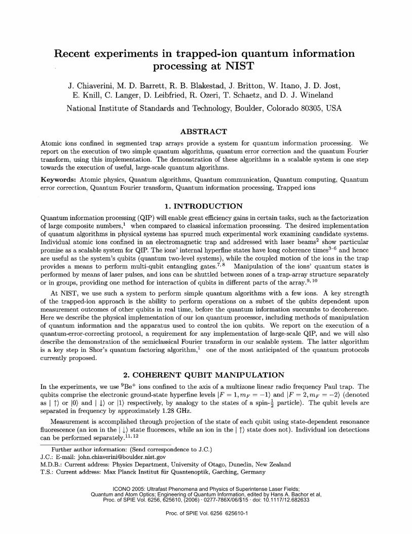
to all orders in the error 9, though they can be corrected such that an improvement in the fidelity over theuncorrected case is attainable for small errors. The fidelity of the corrected final state (as derivable from theaction of the code in Fig. 2a) as a function of the error will be
F(EJe) 1 — 1od21i312(2—3cos6e +cos36e)
(2)
For small errors, the infidelity is quadratic in 9, whereas it is linear in 9 for the uncorrected state. The fidelityreaches a maximum value of 1 for the cases where 232 0. The input states )p (where c = 0, = 1) and
1)p (where = 1, 3 = 0) can therefore be corrected to all orders in 9e for any error XOe with this protocol.
To isolate the basic behavior of the protocol from the technical errors present in the coherent operationsrequired for its implementation, we apply the complete protocol (Fig. 2a) with and without application of theerror-correction operations and compare the final state fidelities. Figure 3a shows the results for the input state
The data are consistent with the theoretical prediction that the state should be corrected for any errorXOe by this QECC. The curves have nonzero infidelity for zero error angle e due to infidelity present in theoperations of the protocol.
Figures 3b and c show similar data for the initial states /öi 1')p _ W'ö )p and /öT ')p —
i'ö7i -1-)p , respectively. As the input state gets closer to the equator of the Bloch sphere (a j3), the
QECC is expected to perform worse (Equation 2). However, the infidelity of the corrected state should growonly quadratically in 9 for small errors as opposed to a linear growth for the uncorrected state. This behaviorcan be observed in the data, which in all cases show an improvement over the uncorrected state.
We also plot the observed rate of the ancillary syndromes for a particular input state in Fig. 3d to verifythat our QECC protocol is correctly detecting errors. The rate F( 11)A) of the syndrome corresponding to noerror and the sum of the rates F( fl)A) + F( tI)A) + F( U)A) of the syndromes corresponding to one error areplotted separately. The rates of the syndromes vary in the predicted manner for increasing error, up to an offsetdue to imperfections in the operations that make up the protocol.
Although an improvement in fidelity over an uncorrected encoded qubit was observed, the QECC protocol asimplemented here induced more infidelity for small errors than would be acquired in an unencoded qubit subjectto the applied error. It should be noted, however, that for errors larger than 9e radian, the corrected statehad higher fidelity than an unencoded qubit undergoing the applied error for all states investigated, and thelogical state was genuinely protected with this protocol. The degradation observed during the execution of theQECC is due in large part to the fidelity of the encoding and decoding gates (ri9O %), and all operations must beimproved to achieve fault-tolerance. In spite of these technical difficulties, the current experiment demonstratesthe feasibility of quantum error correction in a scalable system with resetable ancillae. With improvements infidelity, the execution of the QECC can be made a useful part of more complex quantum algorithms.
5. QUANTUM FOURIER TRANSFORMAmong quantum algorithms discovered up to this time, Shor's method for factoring large composite numbers1may be large-scale quantum information processing's most prominent application, as efficient factoring would ren-der current cryptographic techniques based on large composite-numbers vulnerable to attack. A key componentof this algorithm is an order-finding subroutine that requires application of the quantum discrete Fourier trans-form (QFT) to determine the period of a set of quantum 27 29, 30 In addition, the polynomial-timeQFT is responsible for most of the known instances of exponential speedup over classical algorithms.
Relative phase information of the output state from the QFT is not required when it is applied as mentionedabove; only the measured probability amplitudes of each state are used. This allows the replacement of thefully coherent QFT with the semiclassical, or "measured" QFT,31 in which each qubit is measured in turn, andprescribed controlled phase rotations on the other qubits are conditioned on the classical measurement outcomes.This eliminates the need for entangling gates in the QFT protocol, which, for the trapped-ion implementation,
to all orders in the error O , though they can be corrected such that an improvement in the fidelity over theuncorrected case is attainable for small errors. The fidelity of the corrected final state (as derivable from theaction of the code in Fig. 2a) as a function of the error will be
F(Oe) 1 — IaI2IiI2(2 — 3cos9e +cos9e)
1_J2II2e+O(e). (2)
For small errors, the infidelity is quadratic in 9, whereas it is linear in 9 for the uncorrected state. The fidelityreaches a maximum value of 1 for the cases where IcI2i3I2 0. The input states )p (where c = 0, = 1) and
1)p (where = 1, 3 = 0) can therefore be corrected to all orders in °e for any error XOe with this protocol.
To isolate the basic behavior of the protocol from the technical errors present in the coherent operationsrequired for its implementation, we apply the complete protocol (Fig. 2a) with and without application of theerror-correction operations and compare the final state fidelities. Figure 3a shows the results for the input state
_1_)P. The data are consistent with the theoretical prediction that the state should be corrected for any errorXOe by this QECC. The curves have nonzero infidelity for zero error angle e due to infidelity present in theoperations of the protocol.
Figures 3b and c show similar data for the initial states /i1i )p —i/öi )p and /öT i)p —'ö7i .j-)p, respectively. As the input state gets closer to the equator of the Bloch sphere (a $1), theQECC is expected to perform worse (Equation 2). However, the infidelity of the corrected state should growonly quadratically in 9 for small errors as opposed to a linear growth for the uncorrected state. This behaviorcan be observed in the data, which in all cases show an improvement over the uncorrected state.
We also plot the observed rate of the ancillary syndromes for a particular input state in Fig. 3d to verifythat our QECC protocol is correctly detecting errors. The rate F( 11)A) of the syndrome corresponding to noerror and the sum of the rates I'(I I)A)+(I .l-1)A) + F(I U)A) of the syndromes corresponding to one error areplotted separately. The rates of the syndromes vary in the predicted manner for increasing error, up to an offsetdue to imperfections in the operations that make up the protocol.
Although an improvement in fidelity over an uncorrected encoded qubit was observed, the QECC protocol asimplemented here induced more infidelity for small errors than would be acquired in an unencoded qubit subjectto the applied error. It should be noted, however, that for errors larger than 9e radian, the corrected statehad higher fidelity than an unencoded qubit undergoing the applied error for all states investigated, and thelogical state was genuinely protected with this protocol. The degradation observed during the execution of theQECC is due in large part to the fidelity of the encoding and decoding gates (ri9O %), and all operations must beimproved to achieve fault-tolerance. In spite of these technical difficulties, the current experiment demonstratesthe feasibility of quantum error correction in a scalable system with resetable ancillae. With improvements infidelity, the execution of the QECC can be made a useful part of more complex quantum algorithms.
5. QUANTUM FOURIER TRANSFORMAmong quantum algorithms discovered up to this time, Shor's method for factoring large composite numbers'may be large-scale quantum information processing's most prominent application, as efficient factoring would ren-der current cryptographic techniques based on large composite-numbers vulnerable to attack. A key componentof this algorithm is an order-finding subroutine that requires application of the quantum discrete Fourier trans-form (QFT) to determine the period of a set of quantum 27 29, 30 j addition, the polynomial-timeQ FT is responsible for most of the known instances of exponential speedup over classical algorithms.
Relative phase information of the output state from the QFT is not required when it is applied as mentionedabove; only the measured probability amplitudes of each state are used. This allows the replacement of thefully coherent QFT with the semiclassical, or "measured" QFT,31 in which each qubit is measured in turn, andprescribed controlled phase rotations on the other qubits are conditioned on the classical measurement outcomes.This eliminates the need for entangling gates in the QFT protocol, which, for the trapped-ion implementation,
Proc. of SPIE Vol. 6256 625610-6
a) b)0.6 ______________ 06
I ° uncorrected r° uncorrectedL • corrected L. correctedJ
0.5 0 0.5 00
0.4 04 00
0 00.3 0 - 0 •-C V 0 •,02 .— . . w —
:: kL)P:I!?)P :: ___________________00 0.5 1.0 1.5 2.0 t2 0.0 0.5 1.0 1.5 2.0
t2.5
9e(itI2)2 2 (it/2)2
c) d) ___________________0.6 _________________I 1.00 uncorrected a ç( A)
0.5 L_corrected 0.9 t)A)r( ff)+r( A)0 . 0.8 F(1ttA) theory
a) I ( t)A)r(It)A)F( l)A) °°Y0.4 0
°I :1: A
fo: • .02 a
:00 05 10 15 20 t25 oo 02 04 06 08 10 12 14 16 18
Ge(ir/2)2
Ge
Figure 3. Results of quantum error correction protocol. Recovered state infidelity plotted versus square of the appliederror for corrected and uncorrected cases for three initial states (a—c) and rate of syndrome measurements of ancillae (d).One-standard-deviation errors are approximately the size of the symbols. (a) The initial state is kI-'o)p I 1). (b) Theinitial state is k1'o)p \/öi I 1) i./o:i I 1)p. (c) The initial state is f/o)p V'OT I 1) I 1)p. (d) Rate ofsyndrome measurements of ancillae versus square of error angle. The rate F(m) is the measured probability of obtainingthe measurement outcome m. The data are offset from the theoretical curves because of imperfect gate operations. Theinitial state is k1'o)p V'öT I 1) iv'i I 1) for these data.
a) b)o6 _______________ 06
I ° uncorrected I ° uncorrectedL • corrected L• correctedJ
0.5 0 0.5 00
0.4 04 00
03 0 0030 00 •, •
02 • . .
:: IYfo)P:Il?)P :: ___________________00 0.5 1.0 1.5 2.0
t250.0 0.5 1.0 1.5 2.0
t2.5
6e(itI2)2 2 (itI2)2
c) d) ___________________0.6 _________________
I ° uncorrecte11.0
0.5 L_coreced 0.9 "\ A F( t)A)r( ff,)+ç( A)0 E o. N —r( ttW theory
Q, - - r( fl) )+r( .t) )+r( ) theory0.4 0 0.7 —
0 0 106. A• .
0.1 .— 02
v,v
I1)P-
i s/O,78 1#)p
___________________________________00 05 10 15 20 t25 oo 02 04 06 08 10 12 14 16 18
9e(ir/2)2
Ge
Figure 3. Results of quantum error correction protocol. Recovered state infidelity plotted versus square of the appliederror for corrected and uncorrected cases for three initial states (a—c) and rate of syndrome measurements of ancillae (d).One-standard-deviation errors are approximately the size of the symbols. (a) The initial state is o)p I )p. (b) Theinitial state is k1'o)p ,'o:-j: Dp _ ii'o:i i (c) The initial state is fo)p /iT I 1) I i)p. (d) Rate ofsyndrome measurements of ancillae versus square of error angle. The rate F(m) is the measured probability of obtainingthe measurement outcome m. The data are offset from the theoretical curves because of imperfect gate operations. Theinitial state is k/'o)p \,/öT I 1)p 'o:j i 1) for these data.
Proc. of SPIE Vol. 6256 625610-7
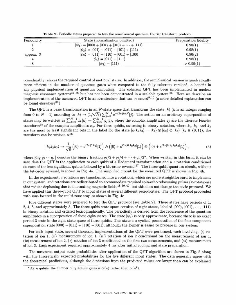
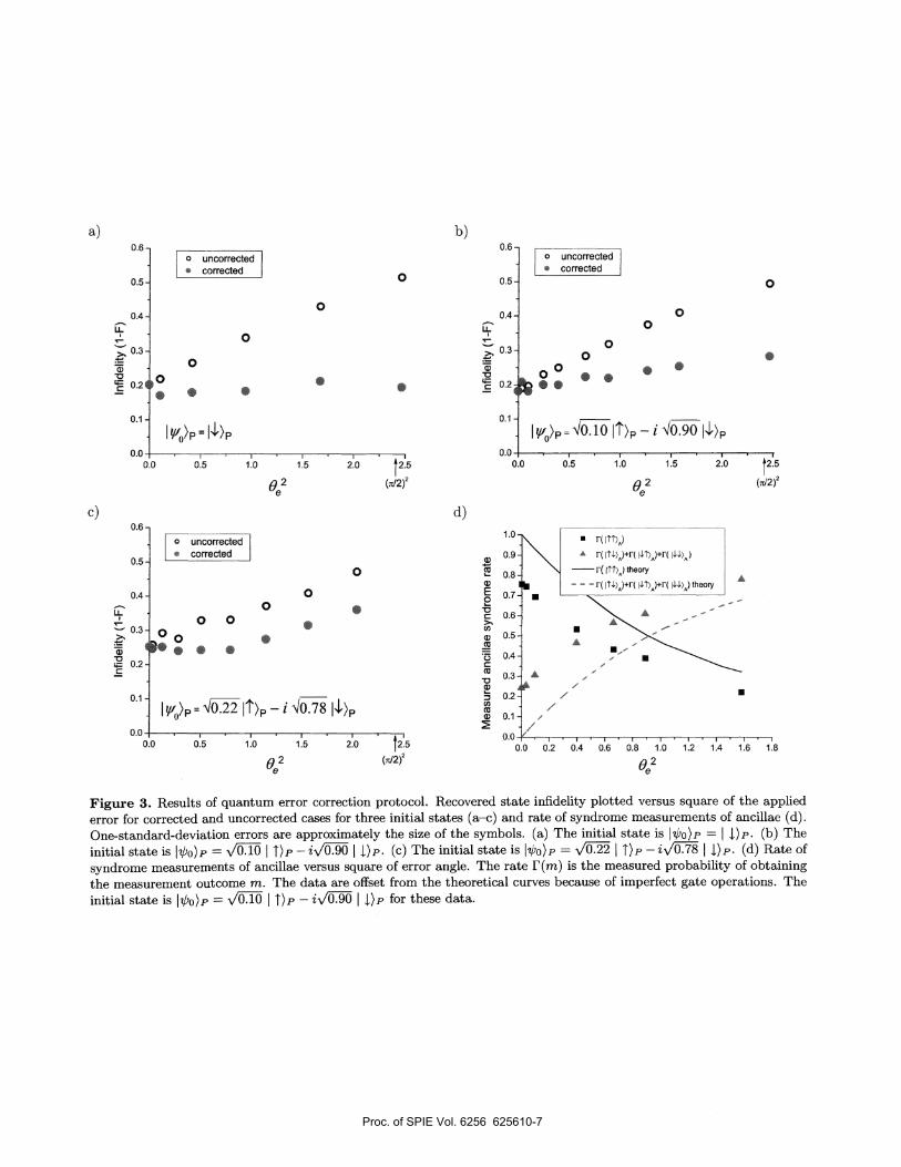
Table 2. Periodic states prepared to test the semiclassical quantum Fourier transform protocol
Periodicity State (normalization omitted) Preparation fidelity1 'b1) = 000) + 001) + 010) + + 111) 0.98(1)2 2) = 001) + 011) + 1101) + 111) 0.98(1)
approx. 3 ',1'3) = loll) + 110) + 001) + 100) 0.90(2)4 kb4) = 011) + 1111) 0.98(1)8 8) = ill) > 0.99(1)
considerably relaxes the required control of motional states. In addition, the semiclassical version is quadraticallymore efficient in the number of quantum gates when compared to the fully coherent version* , a benefit inany physical implementation of quantum computing. The coherent QFT has been implemented in nuclearmagnetic resonance systems3236 but has not been demonstrated in a scalable system.25 Here we describe animplementation of the measured QFT in an architecture that can be al910 (a more detailed explanation canbe found elsewhere37).
The QFT is a basis transformation in an N-state space that transforms the state k) (k is an integer rangingfrom 0 to N — 1) according to k) —p (i/v'W) ' e_i2j/N j) The action on an arbitrary superposition ofstates may be written as xklk) —+ y3 j), where the complex amplitudes y3 are the discrete Fouriertransform38 of the complex amplitudes Xk • For three qubits, switching to binary notation, where k1 , k2 , and k3are the most to least significant bits in the label for the state k1k2k3) = k1) ® k2) ® k3) (k {0, l}), thetransform can be written 27
kik2k3) '(io +ei2[0k3Jll)) ® (1o +ei2[0k2k3Jll)) ® (o) +ei2[0k1k2k3]ll)) , (3)
where [0.qlq2 q] denotes the binary fraction q1/2 + q2/4 + . . . + q/2Th. When written in this form, it can beseen that the QFT is the application to each qubit of a Hadamard transformation and a z rotation conditionedon each of the less significant qubits followed by a bit-order reversal.27 The three-qubit quantum circuit, withoutthe bit-order reversal, is shown in Fig. 4a. The simplified circuit for the measured QFT is shown in Fig. 4b.
In the experiment, z rotations are transformed into x rotations, which are more straightforward to implementin our system, and rotations are redistributed to accommodate required spin-echo refocussing pulses (it-rotations)that reduce dephasing due to fluctuating magnetic 40 but this does not change the basic protocol. Wehave applied this three-qubit QFT to input states of several different periodicities. The QFT protocol proceededwith ions located in the multi-zone trap as shown in Fig. 4c.
Five different states were prepared to test the QFT protocol (see Table 2). These states have periods of 1,2, 4, 8, and approximately 3. The three-qubit state space consists of eight states, labeled 000), 001), .. . , jill)in binary notation and ordered lexicographically. The periodicity is derived from the recurrence of the quantumamplitudes in a superposition of these eight states. The state 'b3) is only approximate, because there is no exactperiod 3 state in the eight-state space of three qubits. This state is a cyclical permutation of the four-componentsuperposition state 000) + loll) + 110) + 001), although the former is easier to prepare in our system.
For each input state, several thousand implementations of the QFT were performed, each involving: (i) ro-tation of ion 1, (ii) measurement of ion 1, (iii) rotation of ion 2 conditional on the measurement of ion 1,(iv) measurement of ion 2, (v) rotation of ion 3 conditional on the first two measurements, and (vi) measurementof ion 3. Each experiment required approximately 4 ms after initial cooling and state preparation.
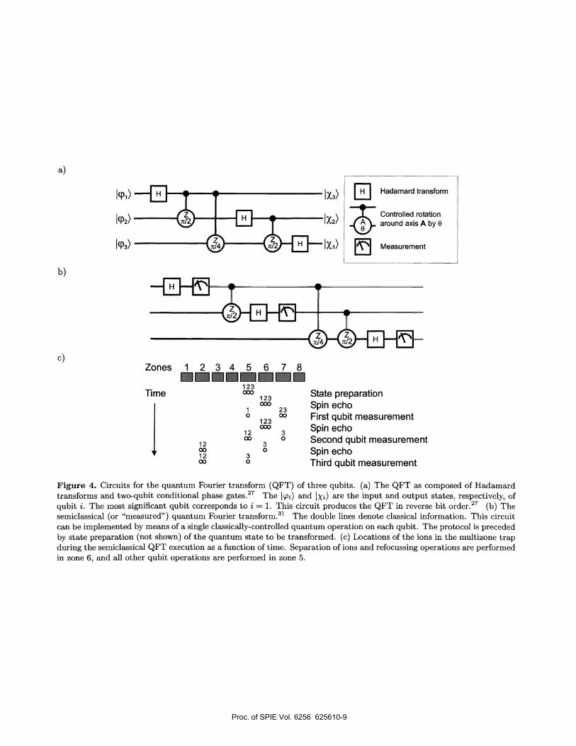
The measured output state probabilities after application of the QFT algorithm are shown in Fig. 5 alongwith the theoretically expected probabilities for the five different input states. The data generally agree withthe theoretical predictions, although the deviations from the predicted values are larger than can be explained
*For n qubits, the number of quantum gates is 0(n) rather than 0(n2).
Table 2. Periodic states prepared to test the semiclassical quantum Fourier transform protocol
Periodicity State (normalization omitted) Preparation fidelity1 = 000) + 001) + 010) + + liii) 0.98(1)2 '02) = 001) + 011) + 101) + 111) 0.98(1)
approx. 3 '03) = 011) + 1110) + 001) + 100) 0.90(2)4 I'04) = 011) + liii) 0.98(1)8 '08) = iii) > 0.99(1)
considerably relaxes the required control of motional states. In addition, the semiclassical version is quadraticallymore efficient in the number of quantum gates when compared to the fully coherent version* , a benefit inany physical implementation of quantum computing. The coherent QFT has been implemented in nuclearmagnetic resonance systems3236 but has not been demonstrated in a scalable system.25 Here we describe animplementation of the measured QFT in an architecture that can be 910
(a more detailed explanation canbe found elsewhere37).
The QFT is a basis transformation in an N-state space that transforms the state 1k) (k is an integer rangingfrom 0 to N — 1) according to 1k) —p (1/v') The action on an arbitrary superposition ofstates may be written as xklk) —f 5' y3 i), where the complex amplitudes Yj are the discrete Fouriertransform38 of the complex amplitudes xk . For three qubits, switching to binary notation, where k1 , k2 , and k3are the most to least significant bits in the label for the state Iki k2k3) =
I k1 ) ® I k2) ® I k3) (k {0, 1}) , thetransform can be written as27
lkik2k3) "
(io +ei2[0k3Jll)) ® (io +ei210k2k3Jll)) ® (io +ei20k1k2k3]ll)) , (3)
where [0.qlq2 q] denotes the binary fraction q/2 + q2/4 + .. . + q/2Th. When written in this form, it can beseen that the QFT is the application to each qubit of a Hadamard transformation and a z rotation conditionedon each of the less significant qubits followed by a bit-order reversal.27 The three-qubit quantum circuit, withoutthe bit-order reversal, is shown in Fig. 4a. The simplified circuit for the measured QFT is shown in Fig. 4b.
In the experiment, z rotations are transformed into x rotations, which are more straightforward to implementin our system, and rotations are redistributed to accommodate required spin-echo refocussing pulses (it-rotations)that reduce dephasing due to fluctuating magnetic 40 but this does not change the basic protocol. Wehave applied this three-qubit QFT to input states of several different periodicities. The QFT protocol proceededwith ions located in the multi-zone trap as shown in Fig. 4c.
Five different states were prepared to test the QFT protocol (see Table 2). These states have periods of 1,2, 4, 8, and approximately 3. The three-qubit state space consists of eight states, labeled 000), 001), .. . , jill)in binary notation and ordered lexicographically. The periodicity is derived from the recurrence of the quantumamplitudes in a superposition of these eight states. The state '03) is only approximate, because there is no exactperiod 3 state in the eight-state space of three qubits. This state is a cyclical permutation of the four-componentsuperposition state 000) + Oil) + 110) + 001), although the former is easier to prepare in our system.
For each input state, several thousand implementations of the QFT were performed, each involving: ( i) ro-tation of ion 1, (ii) measurement of ion 1, (iii) rotation of ion 2 conditional on the measurement of ion 1,(iv) measurement of ion 2, (v) rotation of ion 3 conditional on the first two measurements, and (vi) measurementof ion 3. Each experiment required approximately 4 ms after initial cooling and state preparation.
The measured output state probabilities after application of the QFT algorithm are shown in Fig. 5 alongwith the theoretically expected probabilities for the five different input states. The data generally agree withthe theoretical predictions, although the deviations from the predicted values are larger than can be explained
*For n qubits, the number of quantum gates is 0(n) rather than 0(n2).
Proc. of SPIE Vol. 6256 625610-8
Zones I 2 3 4 5 6 7 8123
Time 000123
I
000
Figure 4. Circuits for the quantum Fourier transform (QFT) of three qubits. (a) The QFT as composed of Hadamardtransforms and two-qubit conditional phase gates.27 The ço) and Ix) are the input and output states, respectively, ofqubit i. The most significant qubit corresponds to i = 1. This circuit produces the QFT in reverse bit order.27 (b) Thesemiclassical (or "measured" ) quantum Fourier transform.3' The double lines denote classical information. This circuitcan be implemented by means of a single classically-controlled quantum operation on each qubit. The protocol is precededby state preparation (not shown) of the quantum state to be transformed. (c) Locations of the ions in the multizone trapduring the semiclassical QFT execution as a function of time. Separation of ions and refocussing operations are performedin zone 6, and all other qubit operations are performed in zone 5.
a)
Hadamard transform
Controlled rotationaround axisAby9
Measurement
b)
c)
12001200
State preparation
I 23 Spin echo0
123 First qubit measurement
12 3 Spin echoCo 0 Second qubit measurement
Spin echoThird qubit measurement
30
30
Zones I 2 3 4 5 6 7 8123
Time 000123
I
000
Figure 4. Circuits for the quantum Fourier transform (QFT) of three qubits. (a) The QFT as composed of Hadamardtransforms and two-qubit conditional phase gates.27 The ço) and Jxi)are the input and output states, respectively, ofqubit i. The most significant qubit corresponds to i = 1. This circuit produces the QFT in reverse bit order.27 (b) Thesemiclassical (or "measured" ) quantum Fourier transform.3' The double lines denote classical information. This circuitcan be implemented by means of a single classically-controlled quantum operation on each qubit. The protocol is precededby state preparation (not shown) of the quantum state to be transformed. (c) Locations of the ions in the multizone trapduring the semiclassical QFT execution as a function of time. Separation of ions and refocussing operations are performedin zone 6, and all other qubit operations are performed in zone 5.
a)
Hadamard transform
Controlled rotationaround axisAby9
Measurement
b)
c)
12001200
State preparation
I 23 Spin echo0
123oo First qubit measurement
12 3 Spin echo00 0 Second qubit measurement
Spin echoThird qubit measurement
30
30
Proc. of SPIE Vol. 6256 625610-9
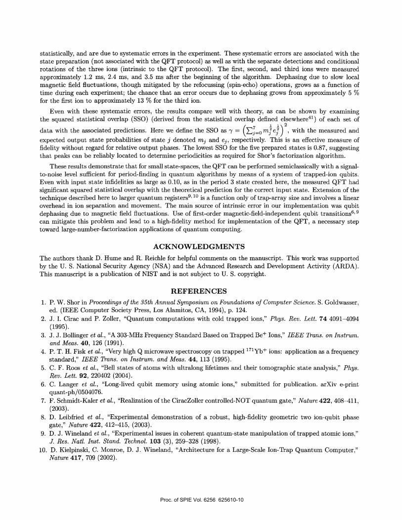
statistically, and are due to systematic errors in the experiment. These systematic errors are associated with thestate preparation (not associated with the QFT protocol) as well as with the separate detections and conditionalrotations of the three ions (intrinsic to the QFT protocol) . The first, second, and third ions were measuredapproximately 1.2 ms, 2.4 ms, and 3.5 ms after the beginning of the algorithm. Dephasing due to slow localmagnetic field fluctuations, though mitigated by the refocussing (spin-echo) operations, grows as a function oftime during each experiment; the chance that an error occurs due to dephasing grows from approximately 5 %for the first ion to approximately 13 % for the third ion.
Even with these systematic errors, the results compare well with theory, as can be shown by examiningthe squared statistical overlap (SSO) (derived from the statistical overlap defined elsewhere41) of each set ofi2data with the associated predictions. Here we define the SSO as y = me:) with the measured andexpected output state probabilities of state j denoted m3 and e3 , respectively. This is an effective measure offidelity without regard for relative output phases. The lowest SSO for the five prepared states is 0.87, suggestingthat peaks can be reliably located to determine periodicities as required for Shor's factorization algorithm.
These results demonstrate that for small state-spaces, the QFT can be performed semiclassically with a signal-to-noise level sufficient for period-finding in quantum algorithms by means of a system of trapped-ion qubits.Even with input state infidelities as large as 0.10, as in the period 3 state created here, the measured QFT hadsignificant squared statistical overlap with the theoretical prediction for the correct input state. Extension of thetechnique described here to larger quantum 910 a function only of trap-array size and involves a linearoverhead in ion separation and movement. The main source of intrinsic error in our implementation was qubitdephasing due to magnetic field fluctuations. Use of first-order magnetic-field-independent qubit 69can mitigate this problem and lead to a high-fidelity method for implementation of the QFT, a necessary steptoward large-number-factorization applications of quantum computing.
ACKNOWLEDGMENTSThe authors thank D. Hume and R. Reichle for helpful comments on the manuscript. This work was supportedby the U. S. National Security Agency (NSA) and the Advanced Research and Development Activity (ARDA).This manuscript is a publication of NIST and is not subject to U. S. copyright.
REFERENCES1. P. W. Shor in Proceedings of the 35th Annual Symposium on Foundations of Computer Science. S. Goldwasser,
ed. (IEEE Computer Society Press, Los Alamitos, CA, 1994), p. 124.2. J. I. Cirac and P. Zoller, "Quantum computations with cold trapped ions," Phys. Rev. Lett. 74 4091—4094
(1995).3. J. J. Bollinger et al., "A 303-MHz Frequency Standard Based on Trapped Be Ions," IEEE Trans. on Instrum.
and Meas. 40, 126 (1991).4. P. T. H. Fisk et al., "Very high Qmicrowave spectroscopy on trapped l7lYb+ ions: application as a frequency
standard," IEEE Trans. on Instrum. and Meas. 44, 113 (1995).5. C. F. Roos et al., "Bell states of atoms with ultralong lifetimes and their tomographic state analysis," Phys.
Rev. Lett. 92, 220402 (2004).6. C. Langer et al., "Long-lived qubit memory using atomic ions," submitted for publication. arXiv e-print
quant-ph/0504076.7. F. Schmidt-Kaler et al., "Realization of the CiracZoller controlled-NOT quantum gate," Nature 422, 408—411,
(2003).8. D. Leibfried et al., "Experimental demonstration of a robust, high-fidelity geometric two ion-qubit phase
gate," Nature 422, 412—415, (2003).9. D. J. Wineland et al, "Experimental issues in coherent quantum-state manipulation of trapped atomic ions,"
J. Res. Natl. Inst. Stand. Technol. 103 (3), 259—328 (1998).10. D. Kielpinski, C. Monroe, D. J. Wineland, "Architecture for a Large-Scale Ion-Trap Quantum Computer,"
Nature 417, 709 (2002).
statistically, and are due to systematic errors in the experiment. These systematic errors are associated with thestate preparation (not associated with the QFT protocol) as well as with the separate detections and conditionalrotations of the three ions (intrinsic to the QFT protocol) . The first, second, and third ions were measuredapproximately 1.2 ms, 2.4 ms, and 3.5 ms after the beginning of the algorithm. Dephasing due to slow localmagnetic field fluctuations, though mitigated by the refocussing (spin-echo) operations, grows as a function oftime during each experiment; the chance that an error occurs due to dephasing grows from approximately 5 %for the first ion to approximately 13 % for the third ion.
Even with these systematic errors, the results compare well with theory, as can be shown by examiningthe squared statistical overlap (SSO) (derived from the statistical overlap defined elsewhere41) of each set ofii2data with the associated predictions. Here we define the SSO as 'y = me;) , with the measured and
expected output state probabilities of state j denoted m3 and e3 , respectively. This is an effective measure offidelity without regard for relative output phases. The lowest SSO for the five prepared states is 0.87, suggestingthat peaks can be reliably located to determine periodicities as required for Shor's factorization algorithm.
These results demonstrate that for small state-spaces, the QFT can be performed semiclassically with a signal-to-noise level sufficient for period-finding in quantum algorithms by means of a system of trapped-ion qubits.Even with input state infidelities as large as 0.10, as in the period 3 state created here, the measured QFT hadsignificant squared statistical overlap with the theoretical prediction for the correct input state. Extension of thetechnique described here to larger quantum registers9' 10 is a function only of trap-array size and involves a linearoverhead in ion separation and movement. The main source of intrinsic error in our implementation was qubitdephasing due to magnetic field fluctuations. Use of first-order magnetic-field-independent qubit 69can mitigate this problem and lead to a high-fidelity method for implementation of the QFT, a necessary steptoward large-number-factorization applications of quantum computing.
ACKNOWLEDGMENTSThe authors thank D. Hume and R. Reichle for helpful comments on the manuscript. This work was supportedby the U. S. National Security Agency (NSA) and the Advanced Research and Development Activity (ARDA).This manuscript is a publication of NIST and is not subject to U. S. copyright.
REFERENCES1. P. W. Shor in Proceedings of the 35th Annual Symposium on Foundations of Computer Science. S. Goldwasser,
ed. (IEEE Computer Society Press, Los Alamitos, CA, 1994), p. 124.2. J. I. Cirac and P. Zoller, "Quantum computations with cold trapped ions," Phys. Rev. Lett. 74 4091—4094
(1995).3. J. J. Bollinger et al., "A 303-MHz Frequency Standard Based on Trapped Be Ions," IEEE Trans. on Instrum.
and Meas. 40, 126 (1991).4. P. T. H. Fisk et al., "Very high Q microwave spectroscopy on trapped l7lYb+ ions: application as a frequency
standard," IEEE Trans. on Instrum. and Meas. 44, 113 (1995).5. C. F. Roos et al., "Bell states of atoms with ultralong lifetimes and their tomographic state analysis," Phys.
Rev. Lett. 92, 220402 (2004).6. C. Langer et al., "Long-lived qubit memory using atomic ions," submitted for publication. arXiv e-print
quant-ph/0504076.7. F. Schmidt-Kaler et al., "Realization of the CiracZoller controlled-NOT quantum gate," Nature 422, 408—411,
(2003).8. D. Leibfried et al., "Experimental demonstration of a robust, high-fidelity geometric two ion-qubit phase
gate," Nature 422, 412—415, (2003).9. D. J. Wineland et al., "Experimental issues in coherent quantum-state manipulation of trapped atomic ions,"
J. Res. Natl. Inst. Stand. Technol. 103 (3), 259—328 (1998).10. D. Kielpinski, C. Monroe, D. J. Wineland, "Architecture for a Large-Scale Ion-Trap Quantum Computer,"
Nature 417, 709 (2002).
Proc. of SPIE Vol. 6256 625610-10
0.8.CoO.62
O.40.2
An
£2CO
£20I-.0.0.4
0.2
An
ExperimentTheory
= 0.99±0.014
ExperimentTheory
= 0.88±0.013
ExperimentTheory
= 0.96±0.014
O I 34 567Output state
Figure 5. Results of the semiclassical quantum Fourier transform. Measured probability of each output state occurringafter the application of the protocol is shown along with the expected transform output. Each plot contains data from5000 experiments. The squared statistical overlap (SSO) 'y, a measure of transform accuracy, is explained in the text.Uncertainties quoted for the SSO are statistical and do not include systematic errors. Panels (a)—(e) are the QFTs forIbi), I2), kb3), kb4), and kL'8), respectively.
QFT of equal superpositioninput state (period 1)
ExperimentTheory
= 0.87±0.013
>.CD.00.c,a,
Cl)CDa,
1.0 QFT of input state 1001)4101 1)-'-l1O1)+I1 I 1) (period 2)
b)
d)
a)
c)
e)
I01234567Output state
1.0
61Output state
67
QFT of input state I001)+IO11)+ 1.0
1100+I1 10) (approximate period 3)QFT of input state 101 1)1-1111)
(period 4)0.8.
CD.2.c,
Cl)CDa,
ExperimentTheory
= 0.88±0.013
01234567Output state
I FO I 2345Output state
67
QFT of input state 111)(period 8)
I .0
0.8.Co0.62
0.40.2
An
>
-o20-c,a,
Cl)a,a)
O.8.0Co-o0.600.O.4
0.2
An
O.8.0Co.00I-.0.0.4
0.2
An
Figure 5. Results of the semiclassical quantum Fourier transform. Measured probability of each output state occurringafter the application of the protocol is shown along with the expected transform output. Each plot contains data from5000 experiments. The squared statistical overlap (SSO) 'y, a measure of transform accuracy, is explained in the text.Uncertainties quoted for the SSO are statistical and do not include systematic errors. Panels (a)—(e) are the QFTs forI'i) Ib2), kt'3), kb4), and kl'8), respectively.
QFT of equal superpositioninput state (period 1)
ExperimentTheory
= 0.87±0.013
a)
c)
e)
01234567Output state
1.0 QFT of input state I001)+I01 1)-FI100)+I1 10) (approximate period 3)
0.8
.0CO
2
0.40.2
0.
ExperimentTheory
= 0.88±0.013
b)1.0 QFlofinputstate f001)-'-fOll)+
I 1)(period 2)0.8
— Experiment.- Theory0.604
02
0.0 — —
d)I .0
_v_,___1
QFT of input state 111)(period 8)
— ExperimentTheory
Y = 0.99±0.014
o 234567Output state
QFT of input state 01 1)1-Il I 1)(period 4)
— ExperimentTheory
.y = 0.96±0.014
01234567Output state
I .0
012345Output state
67
O I 2345Output state
67
Proc. of SPIE Vol. 6256 625610-11

OgOTO96/qd
-unb utid- AIX1 (966T) ii'iN 'nbinbnqjy 'ozxj,s MN jo A!S1A!Ufl qi 'sq Qqd ''PM V 3 TT
(L6T ')TJ0A MN '1AOQ) siitov puv uvuoat mndj 'Ajiq H T P' ujjy j (og6T) o 'o s'f1jj 'soqz UTIS,, 'UqH TE EI 6 (g6T ' •p Tj 'OpUj1 'SS1d c!mpzW) of spot/;idjiv 7VV?Ud'1/WJ1J 'U)TJ1'ç •D ssid rn 'ung
'uiisAs jqjs u unojsui iinoj mnuinb jo uo!mumJdmJ,, '.i T L (oog) LTT9 'TT
•S'flIc[ •wd/3 •f 'ui1oJsU1 1UflOJ uinunb jo Aqdiiomo ssoid 'v U!SU!M S A 9 (goog) 9TJO '99 V '/1/J 'iossoid uo!m1oJu!-uinuirnb ii'mi u UO U!Unoc mnuirnb pu uotmts sqd jo uo!uuiJdmJ,, 'i .s P' 'UOq3 A f s-r
(Toog) 'f7Jf7 d'ThWN 'arreuosi pum iejcnu utsn mqpop upozYej mnrnnb sioq jo uozqi Jum!1dx,, 'i UcIAS1PUA M 1A1 T T
(Toog) 6T '98 7 adj II?JJ 'm1oJsU1 JMJflOJ mnrnrnb jo uo!uuiJdmJ,, 'Aio pu 'pAopj 'ounioj jis '!AUd V 1A1 'UtSUtM S A
(ooog) ggj7g '8 i fldj SfI'l/J 'indmoc mnrnrnb HJNN U mqiop upu-ipio u jo uozji Juui!1dx,, 'iv UcIAS1PUA TI 1A1 T
(966T) gg '91w
•7 .a2q sflj 'uo!ndmoc mnrnrnb ioj miojsui iinoj jsspui,, '!N s-c p' sqfflp [ 3-J T (966T) L '89 IJ poJ4 af 'uiquOp uiopj s1oq 11 uo!ndmoc 'szof T v
(66T) 96TH ioth-j qciesJ J"THI 'UUOZJ mnun rn jnjs miojsurj iunoj uiixoiddy uy,, 'qms1cIdo3 Q 6g
(66T) ggT—gggT 'T8 7 aj sflcj '11s!1 mnunb o suo pdchi jo uoom A!ZXTTOZ UJOO3,, '7V d U[ J [ g
(ooog) Mu 'SS1d AI1S1AIUfl p!1qm13 uozczvwtofu puv uozwzmdtuo utmuvm 'rnnq rj .j pu UST!N v i"i L?
(oog) g09—g09 'i wv 'uono ions mnuirnb jo 'v f (ooog) LO6gL '8J f1iar
•t?PtOL[ 'szdso1d :utsscoi UOffliOjUj fflflUfl pS[ 3-JJAJ,, '7V d A1OJ J gg (Toog) TTg—TTg '98 7 adj S'fI/J 'JO3 UZXiflO3 1Oll
-AtJ qJJ :s1nduio3 mnrnn UpflUUpU[,, 3 pu 'zU!IeJAI 1T ''-'IJT H 'fflU)J I T (666T) T6T—Tg6T
'09 V adj •s'fjj 'poc mnrnrnb u!dmp sqd q-o jo uozpj Juui!1cIx,, ' p Uflj Q (66T) ggT—ggT 'T8 •d7 adf fI?/J 'UOEZflO3 JOfl fflflUfl juuitidx,, 'v Aio j (966T) LLgg—Tggg
'f7 •pU07 •og •f O4[ 'UOZflO3 1Ofl fflflUfl pu UijiUj TZitd JdEJnJAJ, v T (966T) OTT
—6OT 'J V flj •s)fIq[ SIDO3 unoc-ion fflflUfl pOO,, 'ioq d P juq1pj3 3J y o (66T) OTT—g 'f7f7 •pU07 O5 •?:f 4[ 's1ndmo3 mnrnn 'TTPTS1d r 6T .(goog) TLgL9g ' nduio3
•fui •1uvThb 'cFei uoi ji jnp ut suot jo uo!nths pu ss mnrnrnb jo iodsrnrn,, 'v o-j y p (g66T 'plOJXQ 'SS1d uopunJ3) sdvaj uoj 'qsoq ,j d LT
(o66T) OT—T '9 IJ poj,ij adf 'sjcnxed einu pu pnqo ioj schi 'Td M 9T (oog) LTT—9LTT 'io
'sves Tti AdocsorpcI pioj,, 'v (oog) T9T—6T4T 'T9
y puo7 og j s'uatj vqj 'suot pdcFei qt utsszoid uopunojut mnrnrnb,, '7V PUTU!M f Q J7T
(g66T) TTOT 'L W1 (J s'fltjj 'Aiu u!od-o1z o mo punoq jo ujooc umj 'v oiuoj, 3 (oo) ooo ' ay Iqj cnmoy qt utpo3 suu mnrnrnb,, 'v zaTc i oo) 6L—LL '6J WN 'sqnb zmop jo uot iodj mnunb OS!UIm1U,, '7v "J ci TT
OOTO96/tTd
-unb uud-o ATX1% (966T) lAIN 'nbionbnqjy 'ooixj,s N AiS1AiUfl qj c[qd 'RPM V 3 (L6T ')JJOA MON 'JAOQ) SULOW /(/0 JUV dUVUOSdJ lvdO 'Ajiq jj ç pu ujjy j (og6T) o 'o ai uldS,, 'UqH ni i 6
(96T ' •P 'rjj 'opui 'SSOld mpv) I1?Ic[ iof poppij 7VVW/WJ21J 'U)TJ1V 0 8 ssoid iii 'moEics oqjos i u uuojsui ioinoj mnjinnb jissiqoims jo uoiuuxojduxj,, 'v f L
(oog) LTT9 'TT •fI?Ic[ I3 •f 1OI1flO mnuinb jo Aqdiomo ss3oJd 'v USU!M S A 9 (goo) 9TTO '99 V [ 'iossocoid UO!mJOJU!-uJflU13flb 'JJAN " UO SUITJJOJ
unflno mnrnnb pu uoimiso osqd jo uouuxoIduxJ,, 'ooj ptre 'uoq A ''!M T '°'1 ST (Too) 'f7Jf;7 d1ThZVN 'Mieuos1 zoUm
11Iollu Usn UflppoJ uiopj muunb sioq jo uozoi Juow!Jdx,, '7 UdASipUA M JAT T 8 (Too) 6T '98 7 ([ IM 'UUOJSU1 JIJflOJ mnurtb oq jo uo!uomojduxJ,, 'Aio pu 'pioj 'ounioj jis '!A1Jd V JAT 'U0SU!M S A
(ooo) J79 ' •id7 fl[ •'Ic1 'indmoo mnuiEnb TJATN U qM mTIpoT UU-JID1O U JO UO!Zff1 JUOW!Jdx[,, 'l udAs1opuA M ii i (966T) '91w
•7 •a2:[ Ic[ 'uorpnduioo mnunb ioj miojsui iino '!N s-c p-' sqfflJ [ 3-J T (966T) L '89 •f1Ic[ •POI/V 'Uflflpo[ UJOP13J sioq i1 uopndmoD 'iszoç 3j '1iO y o (66T) ?T96TDT ioth-j i:ionos}j J/'IHI mnun ui miojsurj ipno om!xoJddy uy,, 'qmsJddo3 Q 6?
(66T) g9T—9T 'T 7 aj fqj 'ios!1 mnuinb o suo poddi jo uoom Oq uoo3,, "7V 13 [ [ (ooog) MI1 'ppqm
JTSJOATUfl puqun uozvwwfu puv uoWLnd?lio3 utmçtuvn 'unq j j pu USI!N V iN L (oog) 9O9—O9 'J7 WN 'uopiio ioii mnuinb jo uozoj,, 'v T1JOAq3 f 9 (ooo) LO6L '8J flii
•t?PLOL[ 'soodsoJd P'-' SUUIOAOIT :utssoi UOiWJOJUJ WUfl pS[ 'JJSJ,, '7V ld AiOj j (Too) Ng—TT '9 2)7 uI3[ 911?/J 'OO3 UipOJJO3 1O1JJ -AIJ :sindmo3 WflU%fl Up[flUUpUO[,, 'OU1AOJON 3 pue 'zU!J1Jk }T '"-"TJT H '11P'M I 1 (666T) f6T—T6T '09 V •:[ •ftId '°P° mnunb udunp osiqd q-o jo uoizo-j puomJodx,, 'v uno'j j (66T) 'T8 2[ (i[ fI?/J 'UOipOflO3 1O1J[ fflflUfl I1UUI!.Idx3,, 'i Aio3 [ (966T)
'f7 y puo'j •doS •!:[ •O4[ 'uOpflO3 ion wnuin pu oouijiuj ootn 'ouio V (966T) OTT
—6OT 'T V dj •'1/c[ 'E!xEE SODO3 UflOOflOO-JOJ1 ffltlU13fl pOO,, 'ioq M d P' juqip3 3j y o (66T) OTT—g 'J7j7 •pU07 O5 •g •d04J 'sJnduio3 mnun 'Ilpisoid .r 6T (goog) TLgL9g ' nduio
fuj •luvnb "0T J T"P U suo! Jo uoi3fldOS pu ss mnuirnb jo iodsuj,, 'v oAo3-J y p (66T 'P0PO 'SSOJd uopuJiq3) sdzuj uoj 'qsoqj ,j d LT
(0661) OT—T '9 1J pOJ4J fl[ 'sojoixed jeinou pui pnqo ioj sdi ournxxorpo[,, 'Td M 91 (oo) Lf49LTT 'JO
uF:1s 'sos pIuuE ii AdozsoJpod pimoj,, ' v ld ppjqo u T (oog) T9T—6T4T 'T9 y puo7 og j s'uvj ij 'suoi poddi q uissoooid uom1oJu! mnuinb,, '7V puJu!M f c[ J7T
66T) T1OT 'L W1 aj fj,j ctou uiod-oioz o mo punoq jo ujooo uurj 'v oiuoj, 3 (T7OO) OOT7O '6 j siqj 'sqn moy qM u!po3 osuc[ mnInnb,, '7V zip L T
oo) 6L—LL '6T ThVN 'sqnb omo Jo uo! iothj mnrnnb o sutuuoç[,, '7v T 1A1 TT
Proc. of SPIE Vol. 6256 625610-12