wib 67c 0909 - climate. customized. | stulz...
TRANSCRIPT

WIB 8000
WEB INTERFACE BOARD
© STULZ GmbH, Hamburg
AIR CONDITIONING
Index 67CEdition 9.09
TECHNICAL MANUAL


EN/0909/67C/3
This manual refers to the software version WIB 8000 v1.11.
Contents
1. Operation Modes of the WIB 8000 ................................................................................42. The Hardware ...............................................................................................................5
2.1 WIB 8000 board .....................................................................................................52.2 Ethernet patch cable .............................................................................................72.3 WIB 8000 in separate box (option) .........................................................................8
3. Connection / Wiring ......................................................................................................93.1 The Stulz-Bus RS485 .............................................................................................93.2 Commissioning of the WIB module ......................................................................103.3 Adjustments to build up the STULZ bus ...............................................................10
4. Configuration ..............................................................................................................114.1 Settings for the service technician .......................................................................134.2 Settings for the customer .....................................................................................21
5. Operation ....................................................................................................................255.1 Bus view ...............................................................................................................25
5.1.1 Start window .................................................................................................265.2 Menu structure .....................................................................................................27
5.2.1 Menu structure for DX/CW units ...................................................................275.2.2 Menu structure for chillers with C6000 ..........................................................29
Appendix ....................................................................................................................30A1. Software update ...................................................................................................30A2. RTC battery change .............................................................................................34A3. Factory Reset .......................................................................................................35A4. Support ................................................................................................................36A5. Network check list ................................................................................................38
Notice the country specific ESD standards when opening the unit.

Stulz-BusRS 485-1
Ethernet10/100 MBit/s
RS 485-2
Bus 1 Bus 2
WIB 8000
EN/0909/67C/4
1. Operation Modes of the WIB 8000The WIB (Web Interface Board) is an interface between STULZ air conditioning units and the intranet or internet via an ethernet connection. This connection allows monitoring and control of A/C units. On the operators’s side the appropriate hardware (PC or server) and the appropriate software (SNMP client and/or web browser) are necessary. The STULZ controllers in A/C units are sequentially scanned on occurred alarms and availability. In case a cont-roller detects an error or a controller is not available (blackout on the A/C unit), the webside displays this error, an alarm email is sent and a SNMP trap message is sent to the SNMP client. The respective Stulz-controller provides a read out of all operating data simultaneously with the network request (SNMP GET function or opening of a website). In case values are changed via the website or the SNMP client, these values are immediately transferred to the corresponding controller.Every single user can individually choose between the temperature display in n °C or °F as well as among diffe-rent user languages when the data is displayed on the website (http). For website display it is not necessary to allow Javascript or cookies. The individual user settings (temperature, language) are saved simply by creating a bookmark in the browser. It is also possible to assign a sequencing function with the Stulz bus; i.e. the controller receives on/-off commands via the Stulz bus. The sequencing function includes an alarm monitoring and an A/C unit start when limit values are exceeded or passed under.
Following protocols are supported:- SNMPv1 (Simple Network Management Protocol, Version 1)- HTTP (Hyper Text Transfer Protocol), IPv4
up to 32 Stulz units: • C1002• C1010 with SERC1010• C2020 with SERC1010 • C4000max • C5000 with MAX card • C6000 • C6000 Chiller • C7000IOC with EBUS • C7000AT + IOC
PC with web browser
Intranet (LAN)or Provider // Internet (WAN)
Furthermore necessary for the start-up:1. PC or notebook with network connection 2. Cross-over cable or patch cable + switch/hub3. Web browser as e.g. - Internet Explorer from version 7 - Mozilla Firefox from version 2 - Opera from version 9 - Safari from version 3
In addition to this you should have your system administ-rator provide you with all necessary data for the start-up. In appendix A5 there is a form which you should have filled in for this purpose.
up to 32 Stulz units: • C1002• C1010 with SERC1010• C2020 with SERC1010 • C4000max • C5000 with MAX card • C6000 • C6000 Chiller • C7000IOC with EBUS • C7000AT + IOC
The WIB exists, as far as the hardware concerned, in two versions: 1. installed in the electric cabinet of an A/C unit, whereby
it is supplied by the 24 VAC voltage already present in the A/C unit.
2. installed in a separate box with individual power sup-ply.

24V AC/DC
Bus 1
Bus 2
9-30 V DC (+)0 V (–)
high/on
low/off
high/on
low/off
EN/0909/67C/5
2. The Hardware2.1 WIB 8000 board
• Data management of up to 2x 32 Stulz controllers (A/C units) • stand alone unit• no display or keyboard, configuration and service exclusively with a PC via network • independent real time clock. • The software is saved in a Flash ROM. New software can be downloaded from a notebook or PC without the
need of changing hardware. • LED’s show current bus activity and operating state of the board. • The termination resistor for the RS485 busses are activated by internal switches.
Ethernet connection
Voltage freeinputPower supply
Bias
Bus termination
Low High Screen (opt. capacitive grounding)
The voltage-free input can be used to send an e-mail with up to 255 characters when the voltage at this input rises from 0 to at least 9V or drops from at least 9V to 0V.
Setting at the end of the bus:
Setting in the middle of the bus:
Technical data:Supply voltage: 24V AC/DC ± 10%Frequency: 50/60 Hz ± 1%Power consumption: on requestOperating temperature: 5 ... 40°CStockage temperature: -30 ... 60°C

EN/0909/67C/6
Bus activity:Bus 1, red LED when sending data,Bus 2, green LED when receiving data, but also when data is sent, as the WIB checks outgoing data.
Network: Connection established, when LED illuminates
Network: Data transmission, when LED illuminates
State indication
illuminates:WIB ready
blinks:Data is being saved, please wait.
Alarm indication
illuminates:Alarm on at least one controller
blinks:internal WIB alarm (e.g.: e-mail cannot be sent),such an alarm is shown in the eventlog, but not in the alarm window
Function of LEDs

1:1 1:1
EN/0909/67C/7
2.2 Ethernet patch cable (not included)
With a 1:1 network (Notebook or PC + WIB, no switch, no hub) a cross type cable is necessary.The cable length should not exceed 100 m according to the Ethernet standard. When installing the cable take care of not installing it in the proximity of power cables.
free
free
USB adapter cable(not included)
crossed
Net-work
The WIB 8000 housing can be opened best with a screw driver by pressing down the latchings.The front part of the housing at which the board is fixed can be drawn out to the front.

188
164
180
Ø7
188
164
EN/0909/67C/8
Technical data:Supply voltage: 200/220/230/400/ 415/460 V CA ±10%Frequency: 50/60Hz ±1%Protection class: IP 66/67UV resistency: UL 508Fire classification: UL 94 5V
2.3 WIB 8000 in separate box (option)
RJ45 connector for Ethernetvoltage free input, aux in
Power supply
Bus connections

120 Ω / 100 V
......C5000
High Low2 3
C7000ATHigh Low13 14
C1002
High Low33 32
R
WIB 8000
High
C6000
High Low11 12
Stulz-Bus
Low Bus 1
Ethernet
Bus 2
C7000IOC
High Low1 2
C7000IOC
ProviderProvider
EN/0909/67C/9
Stulz Unit 3 Stulz Unit 1 Stulz Unit 32
External termination resistorwith C1002, C4000, C5000
3.1 The Stulz-Bus RS485The STULZ bus is a RS485 bus where up to 32 STULZ controllers can be connected with a WIB. The Stulz bus is an RS 485 bus with fixed transmission parameters such as baud rate 9600 Baud, 8 data bits etc.
Following values are valid for the RS 485 bus: Differential signal is transmitted via HIGH/LOW connection Maximum length: ca. 1000m (3300 feet) Maximal bus participant distance: ca. 35m (114 feet) Maximal bus participant number: 32 Connection: 2 pole shielded data line, twisted in pairs with an impedance of 120 Ω Controllers wired in series, not in star Data bus termination resistor (R: 120 Ω) at the beginning and end of bus
The WIB has its own integrated termination resistor (R). This resistor is activated by setting the switches S1 - S4, when the WIB is at the beginning or end of the Stulz bus.The Stulz bus is a two wire connection with a screen which must be twisted in pairs. The screen must only be connected on one side of the cable to the provided terminals. Connecting the screen at both sides will lead to problems with different potentials.All types of STULZ controllers can be connected in the STULZ bus.- Controllers of type C5000 must be equipped with a MAX-Board.- C4000 controller must be of the C4000max version.
3. Connection / Wiring
Intranet or Internet
with Max board
board
Stulz Unit 64
with EBUS
Integrated termination resistor
Termination resistor:when using new drivers at the other end
Stulz Unit 33 ....
Integrated termination resistor

EN/0909/67C/10
3.2 Commissioning of the WIB moduleTo save the battery for the real time clock, the battery is not connected at the delivery. The connection is done by the jumper J1. See detailed description in chapter A2, page 34.
3.3 Adjustments to build up the STULZ busAll units need their own CPU address/global address (C7000), without any duplicates, so that they can communicate in the bus line (Exception C6000 Supervisor/Controller). They are configured for each controller type as follows:
• C7000AT: command; globadr <globadr> or globid <globid> or menu BMS/Glob. address• C7000 IOC: command: globadr <globadr> or globid <globid> or menu Config/Password/System • C6000: Service / Password / Gen. Settings / Interfaces / CPU-addr:• C6000 Chiller: Service/Password/Settings/System/Address • C5000: Service / Password / Gen. Settings / Interfaces / CPU-addr: • C1002: Menu point CPU-Address chosen with arrow keys • C4000: Ring C configuration / interface• C1010: see C1010 manual• C2020: see C2020 manual
In case of a controller/supervisor combination the following must be observed:
• In a C5000 supervisor/controller combination both controllers receive their own address. Both controllers can be queried separately. Since both controllers have their own sensors they receive the
corresponding actual values from both sensors. When the supervisor does not control you won’t receive any alarms when querying the supervisor.
• In a C6000 Supervisor / Controller combination both controllers have the same address and only the currently active controller responds. You will always receive all alarms and the correct status of the components.
• For the chiller (C6000 Chiller) a configuration with a supervisor is not possible.
After all controllers have received an address and the protocol and gateway addresses have been assigned, the WIB8000 board must be configured. This tells the board, which controller can currently be accessed.
The WIB8000 board has an automatic Stulz bus unit recognition system. With this function all connected Stulz units are automatically recognized and the configuration is registered.The function is called up by the HTTP interface (browser) in the menu "Web interface/bus", paragraph "scan", menu item "start" by pressing the "Send" button.

EN/0909/67C/11
4. ConfigurationYou installed the Stulz-Bus by connecting the controllers by means of bus lines and setting the global addresses. You also linked the WIB 8000 module in the Stulz-Bus and supplied it with power.
Before you connect the WIB8000 with the customer network, it is necessary to adjust the network parameters which are provided by the customer. For this connect the WIB8000 to your PC/laptop first and configure the WIB. The adjusted parameters are updated after a WIB8000 reboot.To connect the WIB8000 to your PC/laptop the following network parameters are adjusted as default settings:
DHCP: offIP address: 192.168.50.52Subnez mask: 255.255.255.0
Important: If the settings which are desired by the customer differ from the settings above, you can not reach the WIB8000 anymore by your PC/laptop after a reboot. It has now been set up for the customer network. Now you can switch on the PC, which also provides a network connection, start the internet browser and call the html pages stored in the WIB module by typing the address http://192.168.50.52 into the command line. Via the html pages you can configure the WIB module.First you are asked to enter the password. Three passwords for different authorizations exist. These are at the moment of delivery:
1. "ganymed" (highest authorization, administrator) 2. "kallisto" (medium authorization, read and write, only levels "Info" and "Operate") 3. "europa" (lowest authorization, read only, only levels "Info" and "Operate")
After you have entered the password and confirmed it by Enter/Return the authorization is shown for a short time, in the example below "Administrator".
192.168.50.52/

EN/0909/67C/12
Pressing this icon displays the alarm list.
Here you set the temperature unit in °C or °F. The temperatures are displayed according to this setting in allen menus.
Here you adjust the language for the display of all WIB pages.
This icon serves to log in when you want to change the authorization and to finish the dialogue.
Moving the cursor on this icon opens a menu, in which you can select whether to display the units by bus or by zone participation.Choosing the bus view, a submenu is displayed in which you can select bus 1 or bus 2.If you select the zone view, a submenu opens, in which only the zones appear which contain at least one unit.
If you click on this icon, the bus view of the two busses is displayed. This represents a possibility to get to the top menu "Web Interface".
The menu line contains five icons to comfortably call up frequently used functions:

EN/0909/67C/13
4.1 Settings for the service technicianFirst you should set the local time. This can be done in the menu "time". The settings done are transmitted to the system and will then be effective by clicking on the "Send" button. Clicking on the "Reset" button resets the para-meters to the default settings. This is also valid for all following menus.Before setting the time you should connect the battery on the board (see A2. RTC battery change). Otherwise your settings will get lost with a power failure.
The internal clocks of all units, which are connected to the WIB8000 by the Stulz bus can be synchronized. In case of an indirect connection (e.g. connection of a C7000AT to a C7000IOC by the IO bus) the C7000AT system clock is not synchronized.The synchronization of the system clocks of all connected units enables the comprehension of the chronological context of the unit/controller eventlogs and simplifies the elimination of complex error causes.
The WIB can update its own system clock by sending requests to a NTP server (SNTP - Simple Network Time Protocol).The synchronization of the connected controllers as the update of the WIB system clock by SNTP request via network, is done at once after the activation of the corresponding function and then with the cycle of the adjusted interval. The following parameters have to be adjusted. A valid NTP server address (server name or IP address), two time intervals (hourly/daily/weekly) and the relative time difference of the local time Ortszeit to UTC time. On one hand a time interval can be adjusted, in which the WIB updates its system clock, on the other hand you can adjust a time interval, in which the WIB synchronizes the system clocks of all connected controllers with the WIB clock.
CET +1:00
CEST +2:00
Sydney +10:00
Canada -3:30
USA, Frederick -5:00
The UTC time is also called "coordinated universal time" and is edited by the NTP server.This parameter must be entered with the following format: <algebraic sign><hours>:<minutes>
CET - Central European TimeCEST - Central European Summer Time
Examples:

192.168.50.52 255.255.255.0
EN/0909/67C/14
The entries for the following three menu windows are defined by the network administrator. In the appendix a form is printed which must be sent to the network administrator before the WIB system start-up so that this data is available for start-up.
Settings for the network (Menu: Web Interface/Network/Setup)
The indication of a DNS address (only IP address possible) is compelling, if server names for other servers (mail, NTP, SNMP Trap) shall be entered instead of their IP addresses.
DNS: Domain name server, network address data base

EN/0909/67C/15
Settings for sending an e-Mail
Settings for using the SNMP protocols
For safety reasons the customer may want to lock the SNMP access. All network modifications are effective only after a reboot of the WIB. You can comfortably reboot the WIB by clicking on the menu item "reboot" in the menu "WEB INTERFACE".

EN/0909/67C/16
The bus will be configured automatically, when you initiate the WIB module to scan the bus and to record all units found in the bus configuration.
For this purpose select for one or the two busses the menu item "Start" of the "scan" function and click on the "Send"-Button. The number of units found is updated each time when a unit has been found.You can abort the scan at any time, when e.g. the actual number of existing units in the bus appears in the case "number of units", by selecting the menu item "Stop" and clicking again on the "Send"-Button.You can limit the global address range which are scanned to save time. Scanning 1200 addresses takes appro-ximately one hour.
To indicate the bus you can give it a name, which refers for example to the location where the units are placed.
In "Timeout" you can set the time how long the WIB waits for a response of connected units. Exceeding this time is evaluated as a communication error. The maximum cache hold time indicates how long data points are available in the cache memory as valid data points.A short cache hold time guarantees actual data but causes high data traffic on the bus. A longer cache hold time reduces the traffic but bears the risk that the data might not be up to date.
Bus configuration (Menu: Web Interface/Bus/Setup)

EN/0909/67C/17
The names of the units found are generated automatically by adding the bus number to the expression "Unit" in the adjusted standard language and after the insertion of a hyphen the global address of the unit. For C7000 IO controllers the unit name saved in the controller, if it is not the default setting "unit name", will be taken.So the unit names are displayed in the bus and zone view as represented below.This name can be modified in the menu "Config/Web interface" for each unit.
Manual configuration of units within the bus configuration
Under certain circumstances an automatic unit detection by the "scan" function in the bus menu is not possible. This is the case if a unit/controller can not be provided by voltage at the time. By menu item "create unit" in the menu "Web Interface/bus" you have the possibility to manually create units.By menu item "delete unit" in the same menu you can remove a unit from the bus configuration, without cutting
the bus wiring. Such could be the case if you want to operate the A/C unit temporarily as an individual A/ unit e.g. for test purposes.

EN/0909/67C/18
Manual creation of a unit in the bus configuration
You can define the A/C unit which you want to add to the bus configuration by four parameters: 1. bus (bus1 or bus 2), if you changed the bus designation, the new designations appear in this menu. 2. global address 3. hardware (controller selection, influences the number of represented parameters the same as the
protocol volume and the unit commands which are used for the communication between WIB and the unit/controller.)
4. type: MC, MSC - these types represent special software versions of the C5000 controller. ECOCOOL: use this setting, if the A/C unit features a C5000 controller with the special EcoCool
software.
In the same way you can manually remove a unit from the bus configuration. For this you only need to specify the bus and the global address.
Manual removal of a unit from the bus configuration

EN/0909/67C/19
Zone configuration (optional)
The possibility to configure a zone in which A/C units are sequenced, has been designed in the first instance for units which do not have a proper sequencing function or for which a sequencing can only be realized intricately. (C1002, C4000, C5000, C6000).In this window you can configure such a zone by entering a name for it and adjusting a sequencing cycle. 20 zones maximum can be defined.The assignment of units to a zone and the determination whether the corresponding unit shall be in standby, when the sequencing starts, has to be done individually for each unit in the menu Config/Web interface.
However the standby units can also be switched on by running units if alarms occur at these units. In the case "valid alarms" you can adjust which alarms trigger the start of a standby unit and the cut off of the faulty unit. Several alarms can be marked by mouseclick while keeping the CTRL key pressed.
Moreover you can define the kind of temperature and humidity values, of which the zone average value is calcu-lated. The measured data of standby units is not taken into account for the calculation of the average.

EN/0909/67C/20
In the lower part of the menu parameters are displayed which can be adjusted individually for each unit to use the WIB zone functionality. These parameters enclose the assignment to a zone (by the assignment of a unit to a zone the zone is created.), the definition of the operating state at the beginning of the sequencing (on/off) and eventually the parameters for an overload start.An overload start for a unit, for which you adjust this, is carried out if the temperature setpoint is exceeded by an ad-justable temperature difference or if the humidity setpoint is passed under by an adjustable humidity difference.For both parameters you can specify which measured value shall trigger the overload start (the average zone value or the measured unit value).
Zone configuration for each unit in menu "Web interface"
You can choose among the follo-wing temperatures:
For the humidity four set-tings are available:
After having done the settings click the "Reboot" button to put the settings into effect. The WIB8000 can now be connected to the internal network by means of the Ethernet connection.

EN/0909/67C/21
4.2 Settings for the customer
This the window for general settings. The physical unit (°C or °F) and the decimal separator are important if you use files which are generated with the data logging, in other programs.The default language is English. By setting the standard language other than English you can have the WIB ope-ned in the language of your country.The default language is also valid for all emails automatically sent, as for their attachment.
Using the datalog function you can have yourself sent e-mails in the cycle of an adjustable interval. The e-mails contain the recorded data, which you can determine in detail in the next menu window, as a csv-file. The polling interval can be set individually for each bus.The same way you can have sent yourself e-mails of the record of all events (eventlog) in the cycle of an adjustable interval. In case of lack of memory in the WIB these e-mails are sent automatically to the adjusted address.
You can have displayed a freely selectable logo in the top right corner of ach page.In this menu you can define the passwords for different authorizations. Password 1 allows the access to the highest authorization level. Password 2 allows except the modifications of setpoints only the display of all parameters of the menu levels "Info" and "Operate". Password 3 includes the authorization to read all parameters of the menu levels "Info" and "Operate".Setting the "Timeout" you determine the delay after which you are logged out automatically when the browser has been closed.

EN/0909/67C/22
Web Interface
Although these parameters appear in a menu which is specific for each unit, the data logger is a special function of the WIB. The data is not requested and recorded by the controller but by the WIB.
You get to this window by selecting the bottom item in the config menu of each unit.Here you can provide the unit with a name, which also will appear in the bus and zone view. With the automatic bus scan the unit preliminarily receives an automatically generated designation.
With the datalog function you can record the chronological course of single measured values. Up to five measured values per A/C unit can be protocoled this way.
The available parameters are:
You receive the recorded data in csv format in the shape of an e-mail according to the settings done in the previous menu or displayed in the menu "Info/data/datalog" with the possibility for downloading.
The bus command "addressed request" is only be supported by C7000 controllers with redesign software and leads to a more efficient bus com-munication because data points are requested in packages.
This parameter is automatically be determined when the WIB scans the bus for units.
The other menu items have already been explained in the context with the zone configuration.

EN/0909/67C/23
Alarm notification
You can enter up to five receivers or time spaces for the notification via e-mail when alarms occur. You can set the days at which this shall happen individually for each receiver (for several days by mouseclick while keeping the Ctrl-key pressed). The time spaces can also be set specifically for each receiver.
SMS notification
When alarm messages shall be sent to an e-mail/SMS service, set the receiver and the subject according to the specifications of the provider.

EN/0909/67C/24
Using the potential free contact
If the voltage at the provided contacts changes in a way that 9V are exceeded or are passed under, an e-mail will be sent to an adjustable address. The e-mail will contain the text in the input case following "0V" when 9V at the auxiliary input are passed under and the text in the input case following "9-30V" if 9V are exceeded.The text can be individually modified and may consist of up to 255 characters.

EN/0909/67C/25
5. Operation5.1 Bus viewThe start point when setting unit parameters via the WIB module is the bus view or if existant the zone view. By the bus view the parameter which characterize the unit and give a quick overview of the unit state are displayed box-shaped, where each box represents a unit/controller/bus participant.
1. Unit name 2. Unit state (online, offline, alarm) 3. Unit type (DX, GE, CW, Chiller) 4. Return air temperature actual value (for unit type DX, GE, CW) Flow water temperature (for unit type Chiller) 5. Return air humidity actual value (for unit type DX, GE, CW) Return water temperature (for unit type Chiller) 6. Operating state (on/off)
If an alarm has occurred for a unit, the unit box is displayed alternately with a normal and a reddish background. Simultaneously the alarm icon in the menu line blinks.
klick!
EN/0909/67C/26
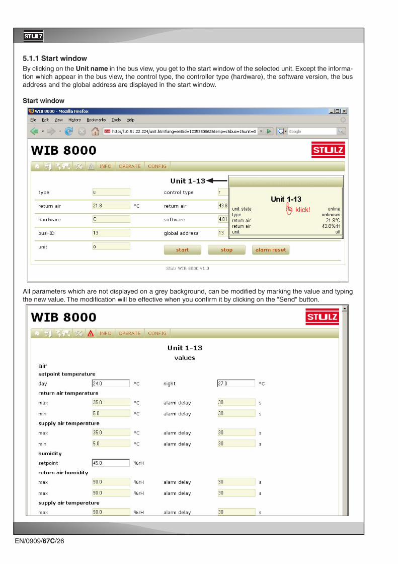
5.1.1 Start windowBy clicking on the Unit name in the bus view, you get to the start window of the selected unit. Except the informa-tion which appear in the bus view, the control type, the controller type (hardware), the software version, the bus address and the global address are displayed in the start window.
Start window
All parameters which are not displayed on a grey background, can be modified by marking the value and typing the new value. The modification will be effective when you confirm it by clicking on the "Send" button.

EN/0909/67C/27
5.2 Menu structureThe menu structure is based on the menu structure which has been applied for the C7000 redesign. The menu line displays three main menus "Info", "Operate" and "Config". In the menu line for controllers which can control several modules, the single modules are displayed (module 1, module 2, etc), the above mentioned structure is displayed on a level below after you have selected a module. The menu structure of the C7000 redesign is however reduced by some menu items for the controllers C1002, C4000, C5000 and C6000.
5.2.1 Menu structure for DX/CW units
Info menu
Operate menu

EN/0909/67C/28
Config menu

EN/0909/67C/29
Info menu
Operate menu
Config menu
5.2.2 Menu structure for chillers with C6000

EN/0909/67C/30
AppendixA1. Software update
We assume the the file "WIB8000.bin" which contains the new software is already on a hard disk of your PC.We will show you how to load the new software in the WIB 8000 without losing the settings which have already been made in the WIB.
For this you must establish a ftp connection from the PC which is connected to the WIB 8000 by a cross type Ethernet line and save the files in the "data" folder of the WIB on your PC.
Then copy the new firmware from the PC to the WIB.After having rebooted the WIB copy the configuration files from the PC into the "data" folder of the WIB. Another reboot confirms and finishes the update.
The steps in detail:
Open a window with the Windows Explorer.Choose the folder, in which the new firmware is located.
Open another window with the Windows Explorer.Enter the address ftp://[email protected] an.xxx.xxx.xxx.xxx stands for the IP address of the WIB 8000.

EN/0909/67C/31
When the registration (log in) has been successful you will see this display.
Enter the Config password (default setting: ganymed) in the dialogue window which has opened and click on "Log in".

EN/0909/67C/32
Open the "data" folder of the WIB 8000 and save the files of this folder on your PC/laptop.
Change to folder ".cfg" in the WIB 8000.Copy the new firmware from your PC/laptop into this folder.

EN/0909/67C/33
Close the "Explorer" frame with the WIB 8000 display.The FTP connection to the WIB 8000 will be shut and the WIB 8000 loads the new firmware.After aproximately 2 seconds the WIB 8000 will automatically reboot.Wait until the "Ready"-LED of the WIB 8000 displays operational availability.Open an "Explorer" frame for the WIB 8000 and registrate.
Replace the files in the "data" folder of the WIB 8000 by the files previously saved.Reboot the WIB 8000 to charge the configuration information of these files.

EN/0909/67C/34
A2. RTC battery change
In the WIB 8000 module a CR2032 type battery serves to provide power for the real time clock, when the WIB is de-energized. You can activate this battery by the jumper J1. When the jumper is removed the battery is not con-nected. Disconnecting the battery could be reasonable for an intermediate storage to save the battery capacity. This jumper is not set at delivery.
Jumper J1 for battery connection
A battery change is necessary, when you notice that the date adjusted in menu "Web interface/time" resets to year 2004.For changing the battery turn the metal clip, which fixes the battery, to the front side of the WIB. The lithium cell can be drawn out of the socket. When installing the new lithium cell take care of the right polarity.

EN/0909/67C/35
In case you forgot the password of the Config level or if network settings have been changed, so that the WIB 8000 can not be reached via the LAN anymore, you can reset the WIB to the factory setting by a jumper on the board.
The steps in detail:
- switch off the WIB- open the box- set jumper J5- close the box- switch on the WIB
- wait until green LED "ready“ is permanently lit
- switch off the WIB- open the box- remove jumper J5- close the box- switch on the WIB
A3. Factory Reset
Jumper J5

EN/0909/67C/36
For trouble shooting it may be useful for the technical support to receive information about the occurred alarms and the equipment of the system.The menu item "event log" records all alarms the same as unit starts and stops, the menu item "overview" shows the hardware version of the system. Both items appear in the menu "Web Interface".The contents of both menu items can be downloaded as csv-files. Send these files on request to the technical support.
A4. Support

EN/0909/67C/37
By menu "Info/Events/Part 1 ...Part 4" the eventlog of a connected unit can be displayed. To keep the time of es-tablishing the eventlog short, the eventlog is subdivided into four parts. Part 1 contains the recent 50 events, part 2 contains 50 events before the recent 50 events etc..The list of events can be saved in the form of a csv file with the possibility to send it to the technical support of Stulz.These files automatically receive the file name "ioceventlog.csv". If you download several parts think of renaming the files as e.g. "ioceventlog_part1.csv".

EN/0909/67C/38
A5. Network check list
1. GeneralUse DHCP: Yes (continue with item 2) No
IP address of the WIB: [ _ _ _ . _ _ _ . _ _ _ . _ _ _ ]
Subnet mask: [ _ _ _ . _ _ _ . _ _ _ . _ _ _ ]
Gateway: [ _ _ _ . _ _ _ . _ _ _ . _ _ _ ]
DNS server: [ _ _ _ . _ _ _ . _ _ _ . _ _ _ ]
2nd DNS server: [ _ _ _ . _ _ _ . _ _ _ . _ _ _ ]
2. E-mailSMTP server: _ _ _ . _ _ _ . _ _ _ . _ _ _ (IP address / server name) _ _ _ _ _ _ _ _ _ _ _ _ _ _ _ (max. 30 characters)
SMTP port: _ _ _ _ _ (max. 5 numerals)
User: _ _ _ _ _ _ _ _ _ _ _ _ _ _ _ _ _ _ _ _ (max. 64 characters)
_ _ _ _ _ _ _ _ _ _ _ _ _ _ _ _ _ _ _ _
Password (plain text): _ _ _ _ _ _ _ _ _ _ _ _ _ _ _ _ _ _ _ _ (max. 64 characters)
_ _ _ _ _ _ _ _ _ _ _ _ _ _ _ _ _ _ _ _
Authentication *: None DIGEST-MD5 CRAM-MD5
LOGIN PLAIN AUTO
Sender: _ _ _ _ _ _ _ _ _ _ _ _ _ _ _ _ _ _ _ _ (max. 64 characters)
_ _ _ _ _ _ _ _ _ _ _ _ _ _ _ _ _ _ _ _
3. SNMPRead community: _ _ _ _ _ _ _ _ _ _ _ _ _ _ _ _ _ _ _ _ (max. 20 characters)
Write community: _ _ _ _ _ _ _ _ _ _ _ _ _ _ _ _ _ _ _ _ (max. 20 characters)
Trap community: _ _ _ _ _ _ _ _ _ _ _ _ _ _ _ _ _ _ _ _ (max. 20 characters)
Trap receiver (IP): [ _ _ _ . _ _ _ . _ _ _ . _ _ _ ]
Trap port: _ _ _ _ _ (max. 5 numerals)
System name: _ _ _ _ _ _ _ _ _ _ _ _ _ _ _ _ _ _ _ _ (max. 20 characters)
Contact: _ _ _ _ _ _ _ _ _ _ _ _ _ _ _ _ _ _ _ _ (max. 20 characters)
Location: _ _ _ _ _ _ _ _ _ _ _ _ _ _ _ _ _ _ _ _ (max. 20 characters)
4. SNTPSNTP server: _ _ _ . _ _ _ . _ _ _ . _ _ _ (IP address / Server name) _ _ _ _ _ _ _ _ _ _ _ _ _ _ _ (max. 30 characters)
Local time offset: _ _ _ : _ _ (±hh:mm)
Synchronize: hourly daily weekly
* Setting "Auto" may result in authentication error when insufficiently implemented at the e-mail server. In case of authentication errors with your e-mail account, ask your e-mail host provider which is the proper
method and select this method deliberately.