wi wow rats112 ic a i atit(i - . – the public's library and ... ia introduction the guidance...
TRANSCRIPT
Approved- "Ilk R. R. RAG AI i NS-CRT - N.1E
Date:).(1117C1 EP UN DIR TOR
AT ION AEOFIATOR5'
r . • / ,i, -74,,z-. . Date:// ECTOR ---- 4 NCE AND, N VIGAT ION PROGRAM
Approved• d D. G. HOAG, APOLLO G
7
• F
TE
CH
NO
M
11441•1
1:1111
144
44,
GUIDANCE, NAVIGATION AND CONTROL
Approved: Date 0r/70 G. SILVER, DIRECTOR, SYSTEM TEST APOLLO GUIDANCE AND NAVIGATION PROGRAM
Approved: 5' t R )ate- .1/ 26 S. L. COPPS, COLO, JECT MANAGER APOLLO GUIDANCE AND NAVIGATION PROGRAIVI
Date• Ti7J
R. H. BATTIK, DIRECTOR, MISSION DEVELOPNIENT APOLLO GUIDANCE AND NAVIGATION PROGRAM
11-577
GUIDANCE SYSTEM OPERATIONS PLAN FOR MANNED CM EARTH ORBITAL AND
LUNAR MISSIONS USING PROGRAM COLOSSUS 2E
SECTION 1 PRELAUNCH (Rev. 21
JANUARY 1970
1sig vs-- CHARLES STARK DRAPER
CAMBRIIDGE. MASSACHUSETTS, 02139 LABORATORY
INDEXING DATA os4LOG
DATE BP11 ,. hs
72:T SUBJECT
1,11i rr 0 -,11-
Approved•

ACKNOWLEDGEMENT
This report was prepared.under ME Project 55-23870, sponsored hy the Manned
Spacecraft Center of the National Aeronautics and Space Administration. through
Contract NAS 9-4065 with the Instrumentation Laboratory, Massachu;otts instivate
of Technology, Cambridge, P.iass.
fi
WI WOW ratS112 IC A I ATit(I
17111 ?.;41

R-577
GUIDANCE SYSTEM OPERATIONS PLAN
FOR MANNED CM EARTH ORBITAL OR
LUNAR ls.IISSIOisiS USING
PROGRAM COLOSSUS
SECTION 1 PRELAUNCH
Signatures appearing on this page designate
approval of this document by NASA/IV1SC.
Approved: Date: 7--1. Thomas F. Gibson Asst. Chief, Flight Software Branch Manned Spacecraft Center, NASA
Date: 7/;:/,
Date: //qS
Approved: James C Stokes, Jr. Chief, hi Software Branch Manned Srpacecraft Center, N
7:2 n' r Approved: ,,...
n`-`- 6 7
Lynwo . Dunseith Chief, Flight Support Division Manned Spacecraft Center, NASA
.e.`" 1/4
iil

1.1 Introduction,
Table of Contents
.... . .
Page
1-1
1.9 CMC Self Test 1-3
1.2.1 Options Available in SELF-CHECK .. 1-3
1.2.2 Procedure to Start SELF-CHECK 1-.3
SHOW-HANKSULI Operating Procedures 1-2
1.2.4 Control of SELF-CHECK Options (F inure 1,2.4-1). 1-4
1. 9 ,5 Explanation of SHOW - HANKSLIM (Figure :.2.5-1) 1-7
L2.6 ERASCHK (•igure 1.2.6-1) 1-7
1.2.7 Check of Hope Memory (Figure L2,7 - 11 . .
1.3 Prelaunch Alignment ProLrrarn Computations, 1-15
1.3.1 Initialization 17.4ta .... 1 -1 F1
1.3.2 Coarse .Alignmont (P01) 1 -15
1.3.3 'y'ertical Erection Computation (P02) 1- 30
Cyrc_)compasinE Computations (1'02). . 1-20
1.3.5 Azimuth Change Computations (P02) 1-20
1.3.6 Optical 'Verification of Alignment (PL131 1-90
1.4 Prelaunch Alignment I-unction:41 1) ,Licription 1-23
1.5 Performance Test Compulatiorss. ....... I -25
1.5.1 C_Iyro 1)rift :Measurement 1-25
1.5.2 \ccelerometer Error Measurement. 1-29
1.5.3 Gyrt, Torquing: Scale Factor Measurement 1 -2 `i
1_6 Functional Description of Performance TestF. ...... . 1-37
1.6.1 Gyro Drift and. Accelerometer Error Test Description . 1-37
1.6.2 [RIG Scale FaCtor Test Description 1-37
1.7 Performance Test Data Analysis 1-A7
1.7.1 [RIG Scale Factor Data 1 -47
LT.2 Gyro Drift Data 1-47
Accelerometer Scale Factor Error and Bias Frror Data 1-50
vti

nate; ,Iani_Eary 19'70
REVISION INDEX COVER SHEET
GUIDANCE SYSTEM OPERATION PLAN
OSOF No. R-577 Title: For Manned CM Earth Orbital and Lunar Missions Using Program COLOSSUS 2E
Section No. 1 Title: Prelaunch {Revision 2)
This cornolele new revision updates the previous
publication, Revision 1. dated October 19 .6B, and
inc.prporates the approved change, listed beIow.
Pea and PCN chanEes are indicated by denoting
the applicable number at the bottom of the page
and by marking the location of the chanEe with a
solid black line at the edge of the page. Editorial
tornattions Und document improvements (nut covered
by PCR/PCM are denoted by a vertical series OF.
black dots.
PCR
DESCRIPTION OF CTIAN.C.;E
B57
Save 3110 Performance Test Words

Date: Qctober 1958.
REVISION MEX. COIrk]Et SHEET
GUIDANCE SYSTEM OPERATION FLAN
GSOP # R-577 Title: For Manned CM Earth Orbital 2416 Lunar Missions Using
Program COLO -6912S f. Ral.r. 237
-Section :21 i Title: Prelaunch (Rev. 1)
Daze Revision Description
Out. 10G8 RCN 596 t it gain in n. rocompassing rig. 1.3.4-1, page 1-18
N 575 Changes per NASA. naaes affecter.;: 1-25, 1-26, 1-2U. 1-29 .1.-40, 1-42, I-51.
Note: PCI1 L, although reflected 2 this document. was Lnadvertently no -r listed.

PRELAUNCH
IA Introduction
The Guidance SyEt ern Operations Plan publiHhed as sLb separate volumes
(33ertions} as listed below!
Section I Pre-Launch
Section 2 rata Linke
e ction 3 Digital Auto-Pilots
Section 4 Operational
ection 5 Guidance Equations
section 6 Control Data
The purpose of this section is to present the program requirements and
descriptions for the prelaunch calihration and te st operations Zor manned CM Farth
Orbital and Lunar Landing Missions usiu program COLOSSUS.
These routines utilize the uplink. capability (described in Section 2) of the CAIC
to load either variables or instruction for utilization or ,execuLf-.3n during the running
of the tests_
The results of the gyro drift and accelerometer uarameter tests are used to
determine or confirm the HOG compensation parameters used for the mission. The
compensation parameters will k,e loaded prior to launch and used durina• themission
to reduce the IllE3 alit-runent and specific force measurernent errors.
This volume con5titutes a control document to govern the test methods and data
analysis equation~ to be used for prelaunch calibration zinc zest.
Revision= to this plan wbich reflect changes in theabove control itern5 require
NASA approval.
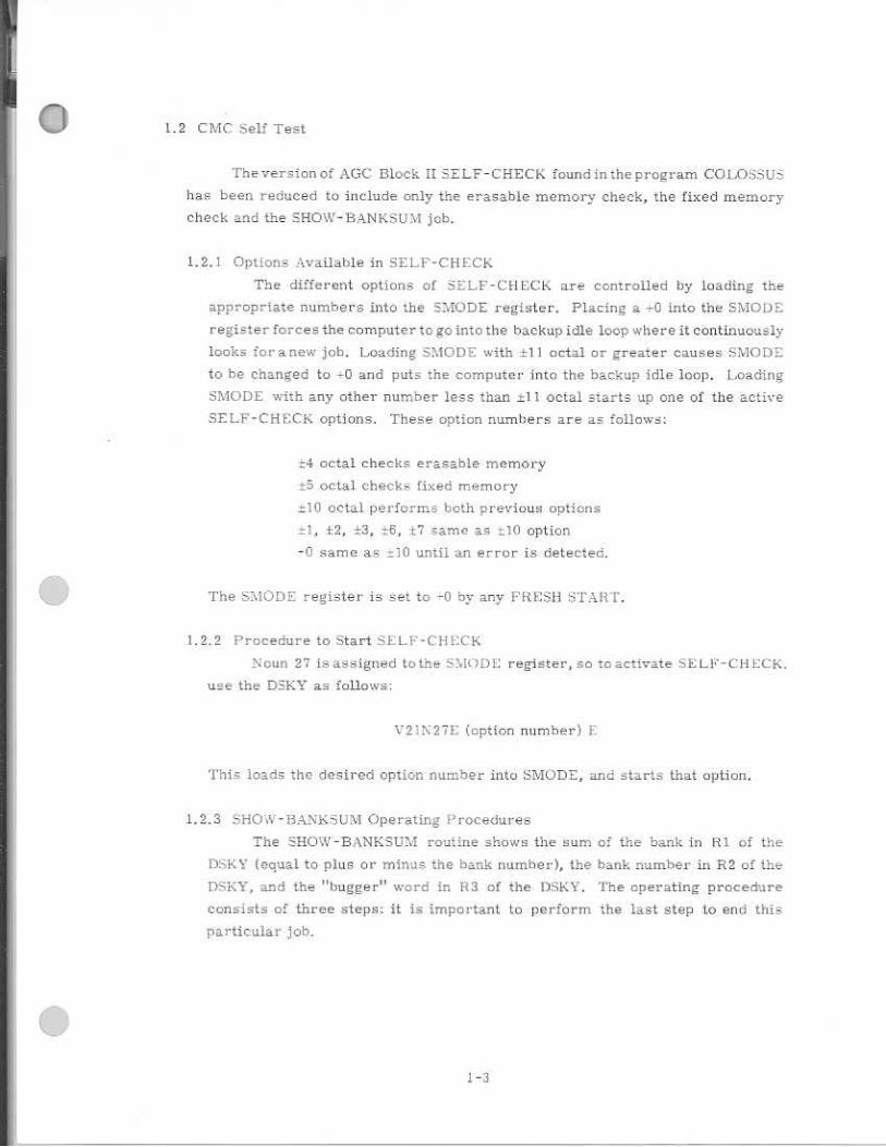
1.2 CMC Self Test
Theversion of AGC Block ii SELF-CHECK found in the program COLOSSUS
has been reduced to include only the erasable memory check, the fixed memory
check and the SHOW-BANKSUM job.
1.2.1 Options Available in SELF-CHECK
The different options of SELF-CHECK are controlled by loading the
appropriate numbers into the SMODE register. Placing a into the SMODE
register forces the computer to go into the backup idle loop where it continuously
looks for anew job. Loading SMODE with ±11 octal or greater causes SMODE
to be changed to -0 and puts the computer into the backup idle loop. Loading
SMODE with any other number less than =II octal starts up one of the active
SELF-CHECK options. These option numbers are as follows:
±4 octal checks erasable memory
±5 .octal checks fixed memory
1I0 octal performs both previous options
±1, ±2, *3, 6, t7 same as il0 option
-0 same as f.." until an error is detected.
The &MODE register is set to -0 by any FRESH START.
1.2.2 Procedure to Start SELF-CH ECK
Noun 27 is assigned to the SNIODE register, so to activate SELF-CHECK,
use the DSKY as follows:
V2:N27E (option number) i.
This loads the desired option number into SMODE, and starts that option.
1.2.3 SHOW - HANE.SU M Operating Procedures
The SHOW-BANKSTJM routine shows the sum of the bank in RI of the
DSKY (equal to plus or minus the bank number), the bank number in R2 of the
DSKY, and the "bugger" word in R3 of the• DSKY. The operating procedure
consist= of three steps: it is important to perform the last step to end this
particular job.

Procedure to START SHOW-EAMCSUM
This routine has its own Verb (9111 No it is very east to mart. The a
information for bank 00 appears in R1.117. and R3 of the DSKY immediately
after startine 51-10W-BANKSI7=0. Verb 05 Noun 01 is uzed to dEsplay this
information. Starting SHOW-BANKSUAT puts +0 in the SMODE register. This
forces SELF-CEECK to go into the ba c kup idle loop.
STARTING pRocEnuRE VglE
(The computer must he hi pro -am 00 0 -..• a 1,1 36E should precede V91E)
Procedure to Display Next bank
The "proceed" verb is utilized to display the sum of the rest of the banks,
Each time the proceed verb entered from the L):';EY, the inform,tion for the
novt higher bank appears in RI, R2, and R3 of the DSKY, If another "proceed
verb enter" is performed after the last hank in a particular rope has been
observed, the information for bank 00 will be displayed again. Continued
proceed verb entries will allow you to observe all the hanks a second tithe.
CONTINUE PROCEDURE V33E or PRO
Pror.edur 'jitop Fl
The operator mast punch in the "terminate verb when he U through With
- rbth terminate= the SITU AT-BAN routine ir1 the
I:.
% -r P ROC .A J.
1,2.4 Control of - C ill ]C_ - N options (Figure 1.2.4-
The prod' ram J.tai'ts at the entry point F:LI'L'kIN after wht ch it stores the
address of the EN 3,SCHb. routinein register Sic check fort new job is
trddC and if no job iswaiting, proceed to te...t register :C.UL)DE. If the contents
or SI1/44( IDE is -F0, idle by looping through the check for a new job or, if greater
than t.10 octal, change SMOI) .: to -0 and idle. I- any other content, of MODE
incrernont the SC:01_7:'.:T r•egiter and test following with either
A, C below_
fi the contents of n:',1C1 DE is =4 perform KH AHC'ti K., the check of erasable
mm-noudlaeramcd in l'igure 1_2_6-1, CNTRC11K, the check of all counters
and other special erasable registers (Figure 1,2,15-2), and CYL the
check of the cycle and shift registers in Figure 1,2.6-3. Then increrntnt
SCUL7T-1 reister, store the address of the HOPECE-IK routine in register
EF=P: and check for a new job starting the erasable memory test option
• 1-4

'17
U
-r
7-`
E

again. Norrnally the program continues to cycle as above until the content.
of smoDE is- chanced by DSKY or until_ an error is detected_
H. if the contents of SMUD1 is L- 5 perform .kOPECHK, the check of fixed
[Ilea-nary in Figure 1.2.7-1. The program then cycles back through the
starting point ..E:1_.1 . 1 : CHK and continues to cycle in a manner similar to that
of option =4. as described in the preceding paragraph.
C. ff the contents of =MODE is - C., ..t.DO octal, t I, :2, ±3, -±6, or =7 branch to the
routine indicated by the address in register f E tl I' 1. For the first pass this
4Arould be the address of ER.ILSCHK. Complete the ERAI -3(.:11K, CN'I'LtC1-1K,
CYC LSH FT loop, At the Start of the second pass, the content of SK EE 1- 3 1 has
been changed to the address of FLOPECFIE. Therefore, after the second test
la the loop of -.VIODE, the hranch (TC i'%I.:EEP1) is to ,It the end
of 1101)ECH1; the program loops through 3ELFC.HK changing iifiEEP1 to
the address of -EP...3.SCHK for the third pass, This alternate cycling of
ERASCI-TE and ROPFCHK continues indefinitely until the content Of SIVIODE
is changed by DSKY or an error is detected. In the event that au error is
detected. the program stores in register tho a.adrese if the location
folluwin the location in SE L.17 - -CH ECK E hat detected the error. TrLi.iddraGs
also stored in the register ADR fov the .11- 111M routine. If LI t.),..-.;C K
is running, the program will also restore the contents of the erasable
registers under test. The register ERIXIUNT (set to -0 by EISKY
STAItT) is incremented and the AL_ IMI routine i called. The ALARM
routine S on the program ai -arni light arLd tey,id . into register FAII,1 -1LC
the alarm code for SELF-CHECK (octal The BBC.r_LN: of -7:.E
is loaded into register•ILMC ADP, -1 and returns. control to the 7;L L IP-C1-1 ECK
program. The contents or is then tested, followed t: or Er.
D. If S'HII5DE - Non-Zero, c.._;-xtent5 in al. which puts the computer
into the backup idle loop.
F:. IF SMODE - Non-Zero, start the option again from the beginning (at entry
point E. L FC FM= I.
If SMODI: is -0, l)ranch on the contents of S1.7., IL to the location in
CHECK immediatelz,. following the location where the.errar w.143 detected and
proceed with the .option from that point.
G, Alarm Di:-•;play; SELF - CHECK error initiaLe.s prngrarn alarm by calling
subroutine ALAR313 with C (A) = CIO r C (ALMCADRI = C 5F-AIL) and
ERCOUNT Incremented by one, The alarm code for self aheck. error
is 01102.E•
1-6

H. in the event that the check for a new job finds one waiting, the job will be
executed and at the conclusion will return control to SELF-CliECK. Since
SET- '-CH ECK is run as part of the backup idle loop it cannot run ag long as
there are any active jobs_
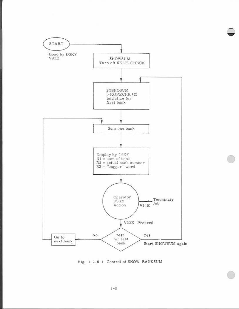
1,2.5 F_KpIanation of SHOW -13A.N.KUM (Figure 1.2.5-1 }
\NKSUPI,1 consis- ts of a routine called SHOW"-U:41.. This routine
essentially does the same thing that the routine 110:).ECILK does; that ts, add up
the sum 7.f separate banks in the rope. After this the similarity ends. ROPECHK
makes sure the sum of the bank is plus or minus it's own bank number while
51-10'.V.53.7).1 displays the sum of the hank in RI of the DSKY irrespective of what
the sum 'nay he. SIIOXSUal .64.15a diuplays the bank number and the bugger word
in Ra and R3 of the DSKY at the same time, The sum of the bank and bank
number in R1 and R2 are shown the least significant bit instead of bits 11-15
(the actual bank bits in the ;:oniviter).
LndouhtedLy the greatest use of this routine will be in restoring the
confidence of personnel in the comp i ter and in verifying that the correct rope
module-5 for a particular mission are actually the ones in the contl, uter package.
Following is a short de7mription of the sunroutine.
Each bank in the rop.-op.: urnaied separately; from the lov,..L.t address to
the highest address used in that bank. The contents of .1 higher address are
added to the sum of the pi -eviou addresEies, If this c reates an overflow condition ,
a ;1 is added to the new sum; a -1 is added to the sum. if an underflo•
condition is created. The Burn of each bank Should be plus or minor; its own bank
number. The gum of the bank is rit;played in FU or the aiky. The hank
number (actual hank number used to gum the bank ...1.'yclert 5 places left) is
displa:...-ed in R2 and the bugger word is displayed in t.ntering a proceed
verb (33) from the DSKY will display the same information for the next higher
hank_ Entering a terminate verb (34) from the E.E.SKY end the SHOW.•31171,1
routine,
1. 2.6 :Hitt (Figure 1.2.6-1 ;
This part or SELF-CHECK makes Sure that A i5 pr,t,ssible to read a 11 1"
and a "10" into and out of each bit position of erasable tharntiry.
STSHOSUM (=ROPECHK+2) initialize for first bank
!lisplay by DTKY surn iii bank
112 = actual bunk numbo:r = "bugger ' ofici
F
TermLnate Job
V24E
Fig. 1. 2. 5- 1 Control of SHOW- BANKSUM

7
to
lo c hec k EDAM.:
D I
uJ 4
I SKEEP
i3 E m
=
■E
lm
Z
— <
111
CL,
Lrl
a--
1.•
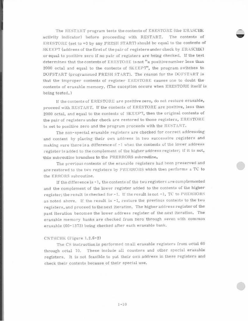
The RESTART program tests the contents of E1-tESTORE (the ERASCIIK
activity indicator) before proceeding with RESTART. The contents of
ESTORE (set to ±D by any FR251-I START) should be equAi to the contents of
SKEE1-1 7 (address of the first of the pair of registers under check by ERASCHK)
or equal to positive zero if no pair of registers are being checked. if the test
determines that the contents of ERESTDRE is not ' l a positive number less than
2000 octal and equal to the contents of SKEET7", the program switches to
DOFSTART (programmed FRESH ST;I_RT). The reason for the DOFSTART is
that the improper contents of register ERESTORE causes one to doubt the
contents of erasable memory. (The exception occurs when ERESTORE itself is
being tested. )
If the comentp. of ERESTORE are positive zero, do not restore erasable,
proceed with RESTART. if the contents of ERESTORE are positive, less than
21)01) octal, and equal to the contents of SKEEPT, then the original contents of
the pair of registers under check are restored to those registers, ERESTORE
is set to positive zero and the program proceeds with the RESTART.
The non-special erasable registers are checked for correct addressing
and content by placing their own address in two successive registers and
making sure there's a difference of -1 when the contents of the lower address
register is added to the conwlernerit of the higher address register; it it is not,
this subroutine branches to the PRERRORS subroutine.
The previous contents of the erasable registers had been preserved and
are restored to the two registers by PRERRORS• which theme performs a TC to
the E1RRO1 subroutine,
if the differenceis the contents of the two registers are complemented
and the complement of the lower register added to the contents of the higher
register; the result is checked for-1, If the result is not -1, TC to PRE Ri-LOW4
as noted above. If the result is -1, restore the previous contents to the two
registers, and proceed to the next iteration. The higher address register of the
past iteration becomes the lower address register of the next iteration. The
erasable memory banks are checked from zero through _even with common
erasable ( C-1373) being checked after each erasable bank.
CNTRCHE. (Figure 1.2.6-2)
The Ci..7 instruction is performed on all erasable registers from octal go
through octal 10. These include all counters and other special erasable
registers. It is not feasible to put their own address in these registers and
check their contents because of their special use,

add 00010 to c.(A)
CS erasable addresses
GIJ through ID octal
CNTRCIIK
Decrement
SKEE.1-12
r NON-IF:110
put G0050 in SKEEP2
and register
go to CYCLEHIPT
Fig. 1, 1. CNTI{Clik

CYCLSHFT
put 25252 in CYR, CYL 1
EDOP registers
acid c(CYR), c(CYL) .,
c(SR), c(EDOP), and a
constant and check that
result is -1
add c(CYR), 6C .iL),
c(SR) .. c(EDOP) .. and NO
+1 and chcek thaT resuli
Ia -1
I increment SCOLTCT -1
NO
ERRORS
go to SMODECHK
(put address of ROPECHK
register SKEEP1, check ior
TWA' j oh and check register
SMODE Ear SELF-CTTECK ovtion.
Fi E. 1.2.6-3 CYCLSiT
• CYCL --!h (Fiaure 1,2_6-.3)
._.al number 25252 is placed in the two cycle registers, the shift
right rE:zi -.er, and the E1)OP register- The contents of these registers are then
twice checked for correct contents.
Check of Rope Nlernory (Figure 1.2.7-1)
The routine for checking the correct contents of a rope 16 called
ii02i-:CHK. Its purpose is twofold. First, it is a cheeg on the conip ._iter. it
makes sure all current driver=, sense amplifiers. and associated circuitry
used in connection with the fixed memory are operating properly. secondly, it
is a check on the rope itself, It ;n. kes sure none of the =ease or inhibit lines
have beorne 81aorted or opened (e ,;sentially guarantees content of rope iL
correct and can be read correoth by the computer).
The sun] of each bank kio.41d he the same as its bank nurnher in the low
order bits:of the computer. A special word, which 1E- called "bugger" word.
is added to the normal sum of the banl as the last word to be added, Tr -ii.F
"E)...a.gLuer" word forces. the slum c -Jf the bank to be plus or rnin!...u., the thank Number,
As an examnple, the sum of bark :93 octal may be 00033 or 77744. Tv..0 "1"C
wa.rd.,.indicate the end of the urnr -ning process for each bank .unle.ss the
hank is full. The "bugger" word immediately follows the second TO SELF'
the hank is full, the"bugger" ward is in the last a- thiresp., and the two
words are no necessary to indic;Ate the end of the sunaming process
for that bank. Of course, all addresses in a hank up to and indiuding the
"1.-ouger ." word have to contain of good parity. Following is a short
description of the ki0;.'1..C111 ,.. routine.
E-:ach hank in the rope it Lirruned separately; from the lowest address to
the highe;L address uqed in that bank_ The content of a higher addre6,L is Addeo
to The curry of the previous addresses, [f this create= an overflow condition, a
.1 is added to the new Fmni; a-1 Es added to the new ;Um if 41-Lunderflow condition
is created. The sun,tof each bank :'could be plus or minus its own bank number.
If the sum ni the hankis its bank nitrnher, the. subroutine proceeds on to checking
the nex-t bank. [f the sum of the honk is not its hank number, SELF-CHECK
goes to the error routine. The bank= are checked in a:4cending order_
1-13

ROPE:Ct./1C
I rn
ALARM
r.ri •0 tn
and I-As
- Li
rr.l. ring te, rhr f.'l I
bran:• 1? n=
L:riow.lum pirt SPC.F.FP C
put fl i
=•1:1-F141.7 to aftdrrcrx
"t" •71.11.VII- 111ti
t.. k
Imink+.1 DO DI
ir:t1.7.11.7:41101• !E. 'ulna .1 111 , 14
fa ll.rn111011 fit.1- r!
5.1,15.1ni frhr ,k fnr n.rn•
jot, hrtwr.r Li t
Istsuaricl nan -c
taro IltrrlharT
dierplay SI.)M 121 Actual lank
Lutriiber and [9] r = in , 414 Et2,
Jiro R.3 thr•
1
1 , 1 FaArt of criArt - lil..
NI
NO
v -raai klrul rat hank lc tr. Iho
chcckpil 151-Ar
a.17LITC;13 I xerl
!. • • • 1
n4 1-.• •
he' Ii. al
r I hr,
Nc
ch-c
indlralrrairm
to Ch4.rk hnnL:c 6!
ge* tr. =tor L htArt•1311.01.V.SUM
Fig. 1.2.7-1 Check of Rope Memory
1-14

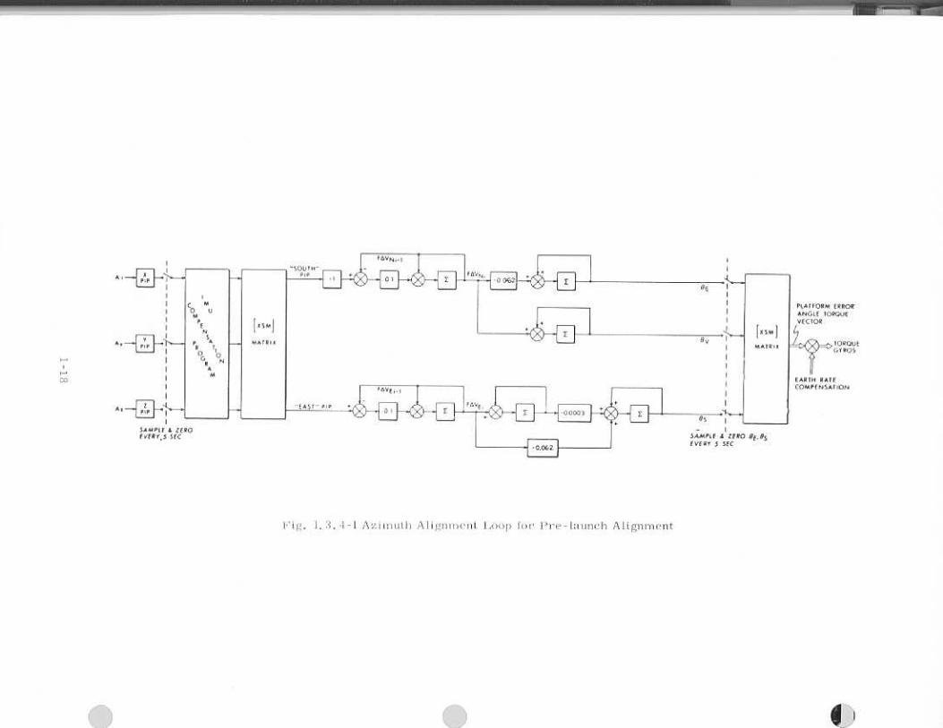
1.3 Prelaunch Alignment Program Computations
The stable member - will he aligned at launch with the stable member Z. axis
vertical, down; the stable member X axis in the direction of the desired launch
azimuth in the horizontal plane; the V axis completes the right-handed triad.
The prelaunch alignment operation is depicted in Figure 1.3-1.
1.2.1 Initialization Data
The initialization data required For• the pre-launch alignment program is
the following:
1. Load vehicle azimuth (VALI, scaled in revolutions, mea- cured clockwise
from north to the Z. axis of the spacecraft.
2. Load latitude of test pad scaled in revolutions.
3. Load desired Launch azimuth (AZ), scaled in revolutions measi.ired clockwise
from north.
4. Load azimuth of optical taraets, scaled in 1 2 revolutions measured
clockwise from north to target,
5. Load elevation of optical targets. scaled in 114 rev...Flutions ., measured from
horizontal plane passing through the SXT focal point.
B. Load performance parameters.
1_3.2 Coarse AliEnment
The computations for coarse signing the stable member as part of 1-he
initialization of the prelaunch alignment are as follows:
I_ Compute the desired 4tablemernher rientaiiun matrix in verti cal,
and east WU-centered earth reference coordinate system.
0 -1/2 (cos AZ) 112 (sin \Z)
i5 NT 1 = 112 (sin AZ) 1/2 (.cos -!!2 1:1 0
2. Zero CDU ti and Wait 10 seconds_
3. Compute the navigation base orientation matrix in a vertical, south and east
EFL-centered earth reference coordinate system.
1; 2 0
0 112 (sin '''AZ) 112 (cos lifk.Z)
0 -1/2 (cos VAZ) 1/2 (sin VAZ)
4. Given thel>1. landIX _ NE
'orientation matrices in the vertical, south and east SM i
coordinate system, compute the CCU angles required to bring the stable
member into the desired orientation. (Ref. 5.0.3.2.2)
1 -15

Level plaice=
ver-ticl erection prog.
U. 3.
lin &if or mukur Thttoff
pr.e.!. •?•
No.
TT:14.7e n'' second,
r2
A/ign Xsm to tile
aZiMali.i.i4;in. gyro-
compc;s8ing proTram
3. 4
L
1! liftaf
bark.op liftoff disc.:Fift ptvEenl?
3-laa
.11r:)V
[ Load initialization
rI97: 7.n-_' init;ate program
'3.., 3_1)
Coar2e align age mernbv.r
7, vHrtiEHLdnwn
X SM “_ a_ 2)
n.tronaut cnreirnarid
ciD optic41
computat5oris
3. SI
Trmister to Pt I
= .540 ror initial vertical eictior.
= 320 for vertical erection per azimuth cliange
Fig. t3-1 Prelauncia-ALIginraern Program. Operation
1-16

1;i !Arc A lign rneil L
1-1
7
lth3LuibliV L1;1E3111:I -„Ia4

Astronaut load new
azirn,_1:11 using ex-tr.Lnded
verb.
1 Rt. ,7 -ati-- X- to the
•
azimuth.
Add :,,z .::nuth change
angle to the vertical
gyro torque command.
Rotate Platform.
Chan alignment
vertical
0.51 mode,
Dc vertical ereclion.
1.s Liftoff
discrete 01' ,17- .F4C- rst?
No
Have
Yes
C nue
ing
COMFU:ations
Transfer
to P11
Fig. 1. 3. 5-1 Azimuth Change Computation
5, Command INTL! gimbals to the CLIIJ angles using coarse align etude,
1,3,3 Vertical Erection Computation {P02}
The vertical erection computations are depicted on Figure 1.3:3-1.
1.3,4 GyrocompasEing Computations (PO2)
The g-yrocompass cornputation2 are depicted c,o Figure 1.3.4-1.
1.3.5 Azimuth Change Computation3 (P02
The azLmuth change cornputatioris are depicted on Figure 1.3.5-1.
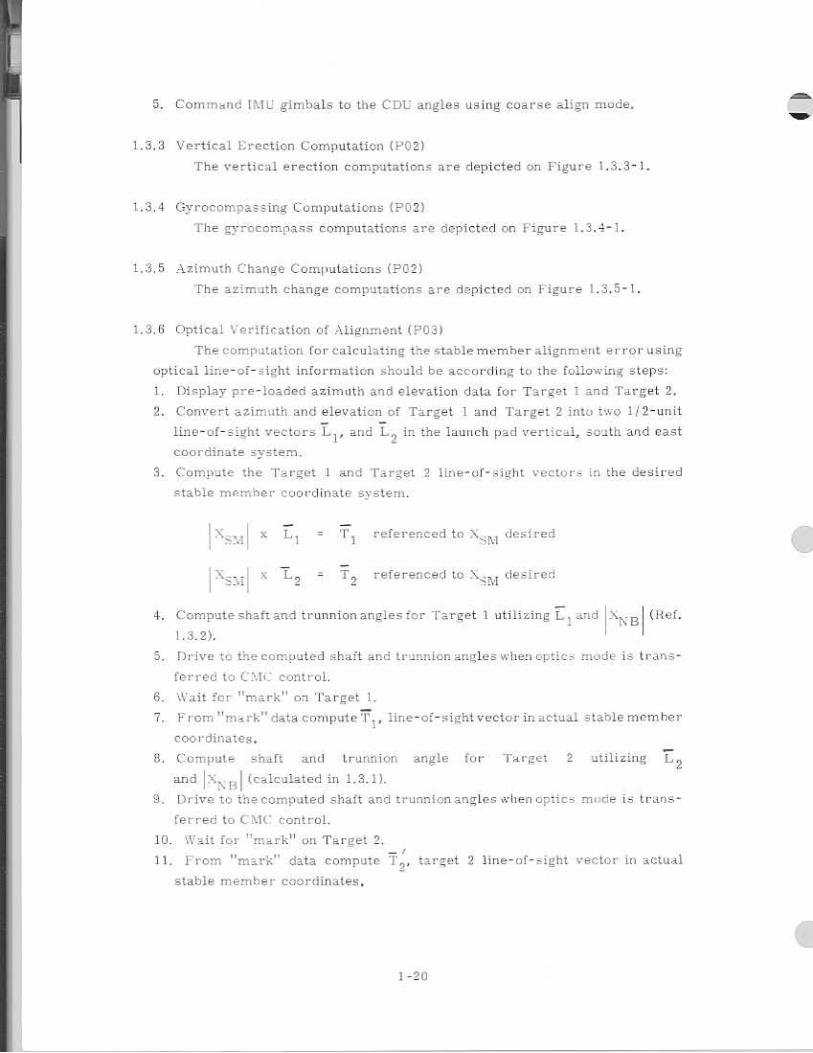
1.3.5 Optical Verification of Align neat (.1. 3 03)
The computation for calculatinE the stable member aliEnrnerst error using
optical line-of-sight information sholild be according to the following steps
1. Display pre-loaded azimuth and elevation•data for Target 1 and Target 2.
2. Convert azimuth and elevation of Target 1 and Target 2 into two 1/2 - unit
line-of-eight vectors L 1 , and L. in the launch pad vertical., aoath. and east
coordinate E.2.- E- .1. em.
3. Compute the Target 1 and Target 2 1ine-of-!F.ight vector,3. in the desired
Rtable rhernher coordinate s.....'sterri,
• 1 1.
-
referenced to N.. desired
x 2 referenced to desired
4. Compute F.hattand trunnion angles for Target 1 utilizinE L. and ?tip B (Ref.
1.&2) .
5.
8,
Drive to the computed shaft and trunnion angles when optics rood& is trans-
ferred to C2.,14 . : control,
Wait for "mark" on Target 1,
7. F roan " I:" data compute '1' „ line-of-sight vector in actual stable rricsm her
coordinates.
8, Compute Shaft and trunnion angle for Target 2 ltilizing L 2 and I X '11 I (calculated in 1.3M.
9. Drive to the computed shaft and trunnion arsgles when optics mode ib trariS -
terred to Ca' control.
10, Wait for "mark" on Target 2.
11, From "mark" data con -puce T oo target 2 line-of-sight vector in actual
stable mernher coordinates.
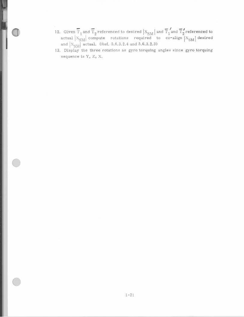
12, Given '1'1 and T
2 referenced to desired IX and T
1 2 and T referenced in
actualI T ^compute rotations required to oe-align IX stvi l desired
and IN =vi l actual, {Ref. 5,6,3.2_4 and 5.6.3,2.3)
13. Display the three rotetion as gyro torquing angles since gyro torquing
sequence is Y. Z,
toi

1.4 Prelaunch Alignment F'..incticnai Description
Prelaunch alignment functional description izin : -Section 4, under P01 ., P02.,
and iiO3.
1

1. 5 Performance Test Computation,.
1.5, 1 Gyro Drift Computation
The physical basis for gyro drift measurement during prelaunch
operations is the detection of the vector rotation of the gravity reaction ac-
celeration. 1 he EMU accelerometers provide thenecessary data. The data is
corrupted by accelerations due to launch vehicle swaying motion and by
quantization in the Pulsed Integrating Pendulous Aecelerometer.
The effect of gyro drift on the vector rotation of gravity is small, therefore
an optimum data processing method required.
The data Is proces ed by a simplified optimum filter which includes in its
state vector estimates of the launch vehicle disturbances. The 13-dimensional
state vector F.:; described in Table I.
The simplified filter design recognizes that IFie gains fur the optimum
filter may be precornputed, since the measurement times will be the same for
all trials and the a priori assumptions for the statistic,-; of the initial state
vector will not change.
The filter gains are precomouteo ;iv operating on a digital simulation. of
the system with a complete linear optimum filter. the gain functions are
reconstructed piecewise in thP CMC during the operation of the filter prdcess
using data loaded into the C ICt rasable memory. The operation of the simplified
optimum filter is depictod in 1 iglu -v. 1.5.1-1.
Figure 1.5.1,1 is a b3ock diagrar., represent Mg the following computations:
A. Measurement
The acceleruructr•rs are sampled every second, The sampled
accelerlimeter °inputs arc transformed in the vertical, north and
east reference coordinate system.
AV x T V
AV
AVs
AV z c
Where XS1.1 I `L the. 1- ti..)n ME trix rrora vertical, south, east earth reference to stable me7:ber coordinates.
The i n of the ts chani;ed ,A.72 —,^.V.:
The meaaurementa are Lmed estimates of south ;;nd
east. velocity. It = s corrected for tne effects of wind
disturbance.

"
po i . p C l AV's (2 9 ) CI = 0.7637633'3
4 Po . pc) a
.".
e C 1..AVe (2' )
C 2 v - po C 2 ±- -0. '2223479
amt = 4(C 2 ve ) Po e
B. Filter gains
The filter gains are pre-determined in the design process of the
simplified filter. The gains are updated every second. The following
gains are used.
1. K 1 multiplies the total pulse counts from the accelerometers (po),
2. K2 multiplies the estimated leveling angles (}. and j3).
3. K3
multiplies the estimated_ a.zmutli axis angle (a). .1. K4 multiplies the estimated vertical gyro drift (dx).
5. K5 multiplies the estimated north-south gyro drift (dy).
6. KB Zero.
7. K7
wind induced sway velocity gain.
S. KB wind induced sway accelerometer gain.
For the first 30 seconds K1
and K2 have the form Ae
(see figure 1.5.1 -2).
K1 0.935e
-0 ' 0912t
-0 208t K2 = 0,262e '
The gains are modified at each sample as follows!
K1 a l = K t [K 1 (0) . 0.3505871:]
K2 a 2 = K2 [1{ 2 (0) = .2626.6423]
K 37 K4, K5, KG are zero initially, then modified as follows:
K.3 + a3 = K3
a4 = K4
K + a._ = 5 o a
K 6 4- a 6 = KG
The values of a l - a5 are applicable over specified intervals. The values
of a l a5 and their applicable inter/e1 are tabulated in Table 2- The
value of a6 is zero.
K 7 = 0.1732993/
K,, = -0. oo83537o
2-26

• C. State vector update
The state vector variables are updated as follows:
a + AM1
(K3) = a
+ AM1 (K
2 ) = 13
1 + AM2 (K2 ) =
Fos + AM 1 (K 1 ) = po5
Po e + AM2 (K 1 ) = P o e
vs + AM 1
(2K7) = v
s
• 4- AM2 (21-(7) e
Ps These parameters are updated during
Pe launch vehicle parameter extrapolation
• + AM 1 (2K 8) = as ae
jr AM2 (2K 8 ) ae
d v + AM2 (K5 ) = d
dx
+ AM 1 (K 4) = dx
D. Extrapolation of launch vehicle parameters.
The launch vehicle parameters are extrapolated for the next
measurement using the following equations:
p(tn+1) =[C1p(tn) y C2v(tn) + C 3a(tn)1 2
v(tn+1) =tC 4p(tn) 1 C 5 v(tn) + C 6 a(tn)1 2
aftn+1) tC van ) T C sv(tn) +Cna(tn)"
Where the coefficients C of the transition matrix are:
C1
= 0.47408845
C 2 = 0.23125894
C 3 =
C 4 =-0.06350891
= -0.16806746
C s = 0.15582939
C 7 = -0.08806784
C 8 " = -0.75079894
C 9 = -0.24878704

E. Calculation of the sines and cosines of alignment angles for ex-
trapolation of platform variables.
This simply involves computation of the sine and cosine of the
various angles using the interpretive trigonometric routines
in the CMC program.
The following functions are evaluated:
sin ta cos a
5in 5
cos p
sin T cps 1.
F. Extrapolation of stable member variables.
The Euler angles for aligning the stable member to the refer-
ence coordinates are computed as follows:
W sm
di
dy 4 Y MM
dz
We (W
sm is the angular velocity of the
stable member)
i" = (.05;3 -s cos 0 0
1 0 -sin-, cos-,• 0 cosy sing
sin3 coKi T.1 1 - sine Cosa.
For vertical drift measure:11E7:ot W. SP.I = W S ,1 + We
7
a cos
1
0
sin ff
sm
c OS 7
sin cosh
c 0 s
sin -r cos p.
cos 7
-Sin a
COB -
Cos
.59737013 40FIR
a a
5
6 (radians)
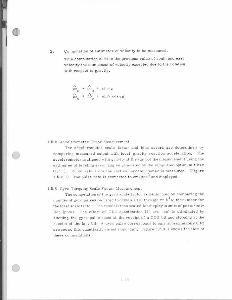
G. Computation of estimates ❑ of vefocity to he measured.
This computation adds to the previous value of south and east
velocity the component of velocity expected due to the rotation
with respect to gravity.
pos
= p❑ g
pa s = poe sires cos -, g
1.5,2 Accelerometer Krror Measurement
Tne accelerometer scale factor and bias errors are determined by
comparing measured output with local gravity reaction acceleration. The
accelerometer is aligned with gravity at the start of the measurement using the
estimates of leveling error angles generated by the simplified optimum filter
(1.5.1). Pulse rate from the vertical accelerometer is measured. (Figure
1.5.2-1). The pulse rate is converted to cm" ec 2 and displayed.
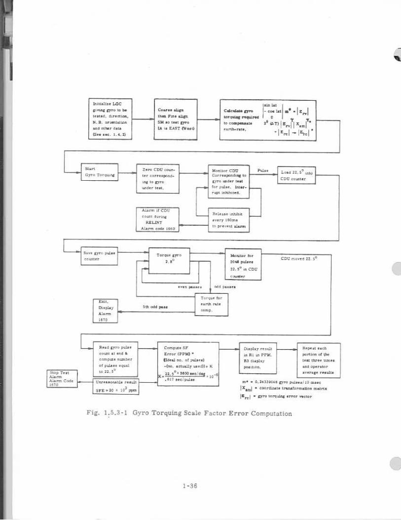
1.5.3 Gyro Torquing Scale Factor AIeasurement
The computation of the gyro scale factor is performed by comparing the
number of gyro pukes rrIquired to drive s. CDU through 22.5 ° to the number for
the ideal scale factor.. The result is then scaled for display in units of parts/ mil-
lion (pprnl. The effect of CD1.; quantization (40 arc sec) is eliminated by
starting the gyro pulse count at the receipt of a CDU bit and stopping at the
receipt of the last bit. A gyro pulse corresponds to only approximately 0.62
arc sec so this quantization is not important. Figure 1.5.3-1 shows the flow of
these computations.

TABLE 1
Prelaunch Calibration State Vector Components
1. Azimuth. Alignment Angie (a)
2. South Axis Leveling Angle (0)
3. East Axis Leveling AntIle (7)
4. South PI-PA Velocity Increment (po s )
5. East P(PA Velocity Increment (pod
6. Launch Vehicle Velocity; North-South (v s )
7. Launch Vehicle Velocity; Fast-West (v e )
B. Launch Vehicle Displacement; North-South (p e )
Launch Vehicle Displacement; East-uVest (p e)
DO. Launch Vehicle Acceleration; North-South (as
)
13. Launch Vehicle Acceleration; East-West (a e )
I2. South Gyro Drift OA
13. Vertical Gyro Drift (six)

(In.ici Lilnos-xil,zoN ado's)
Sin ... __
Cl
1'
'7
C
L
tEl
r.L.' L
l) •-•1
so
in
SD
C
D
=
C)
CQ
0
,C
1 eq
R
-I C
C
ICI
""-.. •-•
0
0
C)
en
in
•-+
..-P r'
0
0
C.
0
,t
'ZI. --+
N
= 4
00
0
00
00
=0
00
.0
co
o
0 r:3 0 0 n
- c 0
0
0
0
Cn
CtcO
on
0
17
.7
.7
.,
1 II
00
.010
•700C
, 0
IIIIP
I
-- — ,
a 4 (Slope
Vertica l Drift )
—•-•-.—
.-
CD
1 n
('
—
V-
C*1 r•-
71
0
CO
.=.
0
na
tr.
.-4 c
i •-•I
.•-•IN
WO
P
1 ̂q
-.
0
c.a c..1
e.-,-.. 0
CL
-4
eq
0
C
C)
0
0
0
0
4.-.4 •1•
oa
,-i
0
CI
C
C)
CI
0 0 4=
1 0
0 C
0
0
0
C3
iD
0
0
0
0
0
0
0
0
0
0
0
IZ
, 0n00=
0000000
n cnn
al 0
00
0
ci .utc:.
0
0
V'0
.r..-'
0
0
ED
0
0
CZ: 0
IIIIIrli
(aT2tre ti4nuilzv adoicz)
Et
PI
C.
t-
(N
t-•
S
ci
Ln
C
D
N-
..7q .r...
CO
,-.
Cl
In
=
co
•n-.L. L
n
,-4 0
C
o
=0
10
*T
b-0
00
00
=0
,. ,.1-(7
•••t•-
-i•
..r1
-00.C
.-2.-1,72o
°00000000000
° 0
0
0
C
. 0
0
0
0
0
0
0
C
10
00
=
(i3
g g
g
g g d ig g
g
•f_.: •.:14
a2 (Time Cons tant Leve ling Angles.)
I--
117 L'''-
-
E'^
.4'
C%1 N
I 17?
Ln
N
-
co.
I1 --r
cct LC
r•-
CO
D
I .1;15
17; ; ft
in
rl
in
0
.4
•zr C
1 .4
N
ir%
• 0
cry 1
• un
ct
cc
co
.-, up
❑b
..-1
trl --4^
r-, 0
7
CO
Cl.•.:*3
CO
Cr:
OD
CO
0/
.7. ci
•-k *:.
Cr= =
C
r C
I C
a. C
I) C
r C
l C.-
C)
OD
C7)
cr= pl
172 .'m
C
I= ❑
1 i;r5
at.
ar- 173
i a
bn
a s•••
so
d.
0C
-4
00
00
0=
In
no
(Time Constant 3PIPAI Counts)
pi
-. 77
7
{'4
kr:. in
er}
•-'1 .1.
ED
ef5 cra
(N
..= EC
C
'El'
EIP cn
0
..
.1
CO
R-4 0
Z
.T.44 4'1
CO
CO
C
> C
O
D : D N
0
eq
•-+ C
C
.3 dzt
CFI
-.7, t-•
l% tin.
ca
M
c4 r-
lz= t--
C9
'4,
73
.14 trI
LC
Nr
CN1 •-.1
.07 0
: in
C
] P5
Cl
a)
Cri
G7
C:
'-I
CD
C
f:. 7
- a
, C
) C
) C
S
ne
rym
n
177 D
o cr.•
I=
Cla C
) O
a C
r) e
b
Cr
0
C)
• • .a
.•••••
• • .•
{M
CC
00000 00 00
(OpU0oaS)
aw ix -.
=
000000
00
00
00
00
0
in
al
C,
10
LI.D crs
C...) N
-' .-.4
t' .1-
in
7 'T
-", f l'i
- 7 7
'7
T 7
T
0
,., 0,
0
0
Les C
) 0
in
o
!:-... to
.•
N
.1. t--
na
N
. .-k
t•-• qd
T-1. ,-.I
El
(*a in
Time Constants and Slopes
• 1 -2
1

Calcula te s ines and
var iables
varia bles ac cor ding to plat -
Extrapolate s table mem ber
for nex t measuremen t
Extrapo la te launc h
vehicle pa rame tfIrs
In s tate v eu tQl .
PIPA e . , • : : 1 Lm ents
Compute es t ima te
veloc ity to be rn r
oeon strui c t g Fl
curr ent m easure tnert t
Operation or the Simplified Optimum Filter
•
I-3

24 12 16 20
TIME (SECONDS)
I 1 1 ;4 1.5,1 Cain A/art:Aim -I with Time.,
a 8 4
CURVE
A 8
Lr. 28
0.24
0.20 1.0
0 0
0.16 0.8
GAIN
0.12 0.6
0.08 0.4
0.04 0.2
0.262e -0.208t. K 2 urve A
0,935e-0.0912t F,.- 1 (Curve B)

GAIN (x10 -3)
- 20
- 40
500 1,000 1,500 2.000 2,500 3,000 3,500
60
40
--K 5 ( NORTH-SOUTH DRIFT)
TIME (SECONDS)
Figure 1.5.1-3 Gain versus Tirne
20
K4 (VERTICAL DRIFT)
—K3( AZIMUTH ANGLE)

a
E
arth [la te
seiut ted FIFA as T2
s tare FI FA countN-
Stor e the con tents rif t he.
✓
enaE of 4 C V .f emit w keeted
Conipm e A n dm.' A T
c. <
LL
-.3 5
_al
Marmot CDU CorrmaperulTOM In
"yria tra-adr Tied
for Pale. Inter-raps Inhibited_
Releaar uWLle
every darn ■
ea prevent alarm
Mord for PO r
20 al pada el
22. 5° CDU
r warder
!earl
Zero CDT;
gyro Torquing ter corremporid,
ins to gy ro
wsdar teat.
Alarm If CCU
count during
patuirr Alarm coda iaEO
51•Vt 'yr,. piaLat Torque gyro courtier 3.10
F
a Load 12. 5.3 ij04.
C1713 a-orator
CDT; inured 22. S °
••116 PM* ■
Emu.
La a play
Ala rim
Let°
bald pa
Tarsus for
earns We
mimp, 5th odd pass
.givlttaLter LOC
salmi" rye.° 'al be
Maud, &realm.,
N. B. ae urraaT Ina
and Warr dais
Compse alma
thin nag align
SK so twat tyro
TA I. EAST Cl'es0
lila lot
Cicalas gyro - cos Intl all cr. !
torontm roquireil to coraperiaaie
76 4111 1 2m I xam+te
• a rih.rats,
1■1/..
tee roc. T.
Seep Ton Alarm Alarm Code 1870
Reed ,pra paLet
coast al 444 Ili
campgta Tuner
of polo** equal
1e n. S'
Urireesonahle rand-1
STE .10 T 103
pp=
Complete
En-or IPPle'
"Waal ao. of palter)
-NO. actually ase-1311• K
23_ s ° 1400 ate; On X. .10 •
..53; arcipe.1aa
-1 Misplay restat
La R1 in PPIL
113 Olaphy
Pointzaa,
Repeat each
portion of the
tree darer times
arid oparaTor
average results
41" O.. 24330"5 Oro Para./ 10 .3.
ixind • COOrdinata Traradaroaajko roatna
lett I /biro toreransi error rector
Fig. 1.5.3-1 Gyro Torquing Stale Factor Error Computation
1-36
1.6 Functional Description of Perforn=ce Tests
1,6.1 Cyr° Drift and Accelerometer Error Test 1Descripton
The urc and accelerometer calibration program recuires
of approximately 41){) erasable memory addresses prior to starting the test.
The complete determination of the performance parameters requires repeat
of the test 13 times. Each repeat test will reorient the platform with respect
to the followiag reference eoordinae system:
a NI-N
-
in the direction of local gravity
Y axis ;Loi-itb
Z axis
-
east
The initialization data include constants for deterrninaEon of filter gains
(1.3.1), desired stable member orientation, spacecraft latitude and azimuth
and test coding.
The initialization data must be ore - loaded for each of the 13 repeat
tests. Each test is terminated with a FRESH START 0,136) and assumes a
FRESH START has been executed prior to its initialization,
The folio..ving flow diagram Bro -rrides a detailed description of the
operation. 1.6.1-1)
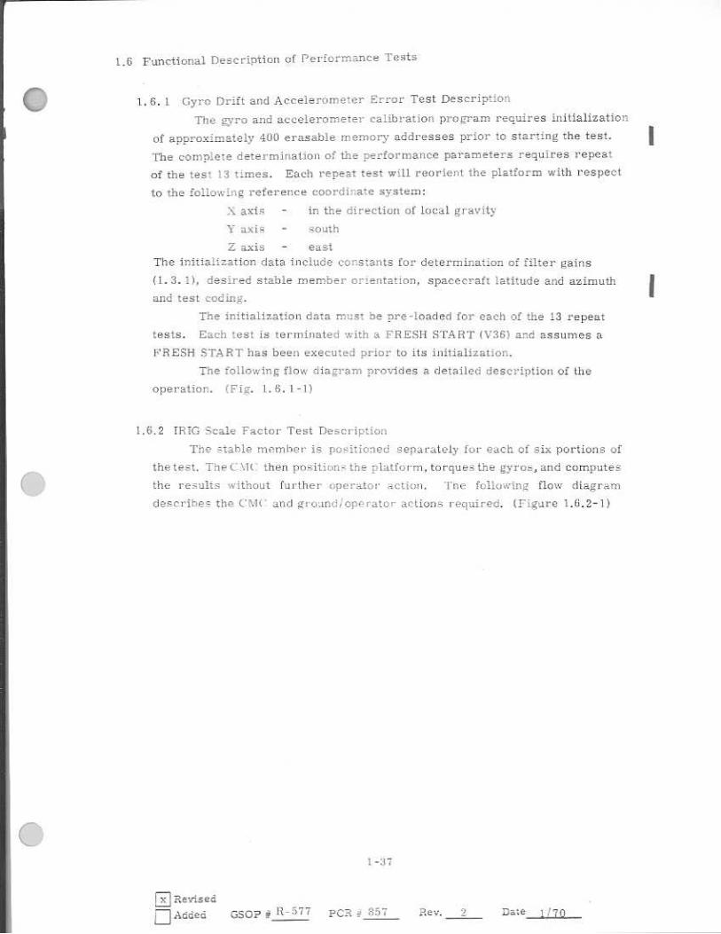
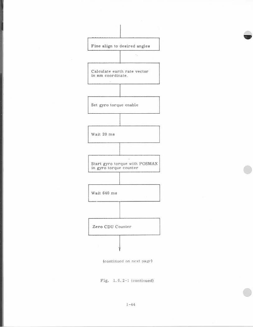
1.6.2 TRIG Scale Factor Test Description
The , -tahle I-timber is positio: -Eed separately fur each of six portions of
the test. The CATt • then prx4iion-: the pialforrn, to rque.. . the gyran, and computeS
the results without further operator action. -ft-se following flow diagram
descrihels tha CM(' and gro;irsde l opPrator - actions required. 1,Figure 1.6.2 - 1)
1-371
Revised
Added C-5,0p 1t- 577 PC=Lt
Rev.
Date 1170

Initialize program. Set
mode 07. Display latitude
and azimuth. VERB 06 N41
Azimuth ± XXX. X.X DEC
Latitude t XX. XXX DEG
NO YES
VERB 33 ENTER
Load correct
azimuth and latitude
VERB 24 NOUN 41
ENTER
Azimuth = X.XX, XX ENTER
Latitude = XX. XXX ENT ER
I Calculate coarse align
angles to position stable
member to preloaded
orientation
Is Azimuth and Latautiu
correct 7
C MC OPERATIONS
OPERATOR OPERATION COMMENTS
Load K-Start tape with
Initialization data
start program V25N26E
20001E XXXXXE YYYYYE
(where XXXXX starting ad-
dress and YYYYY 7. contents
of BlANIO
V3OE
Fig. 1.6,1-1 Gyro Drift and Accelerometer Error Test Description
(continued on next page)
1 -38
csop # R-577 PCR 2.57 Rev. nEae 1 '711 1-7 Revised
El Added

cb.erve NOATT light on
tisKy
ii Cosrme align gimbals
j Do calculated gimbal enil)es result in gimbal lock?
Check for computation
overflow
YES NO
CbAnge IMU mode to inertial
WR5t N 4119 seconde
Sample IMU accelero-
meters every t ilfirnpld
and estimate southerly
gyro dr tft
NG
Overflow Overflow. Occurred
Has Agri
seconds
eLopei ed
NO YES
Turn on alarm 01000 Terminate tent
OkIC Operations Cperator Ope Nal= Comments
(Continued on next p-age)
Premetiee of IMU or CPU fail signal at thin time will result in auto-matic tent termination t17 will be blanked mode lights Alarm code Clifi01 di ■
-played
Possible causes of over-
flow are large initial align-
ment errors, 5 °} errors Ln
irtibialization load or degraded
accelerometers
Ouserve alsrm
determine cause fcr
system failure
Terminate irprt
with VIRE,
Fig. 1.6 .1 -I (Continued)

Dis play south gyro drift
VERB 06 NOUN 98
RI:IXXXXX./ ERU
R2: XXXXX
R3: XXXXX Position code
Do I wish to proceed to
accelerometer error measure-
ment
NoI
VERB 36
ENTER
'1•;--57 terminated
Load K -Start tape with initialization data
Y42.9
PROCEED
Align platform to local
vertical using estimates
of leveling errors com-
puted by previous test
section. Correct for
earth rate errors
10v7vi . niira• vertical mule, 5
Determitir rate of vertical acceler-ometer C8arlp align to 0 , n , 0 after rate determination
4 Display measured
gravity
VERB 06 NOUN 98
111.:=XXXXX.1 1 11
R2: XXXXX
R3: Position Code
q
Load estimates at prev-
iously measured east-
west drift.
(continued on next page)
Do .1 wish to proceed to
vet heal drift measurement
YES NO
PISIOCE ED VERB 36
I ENTER
Test terminated.
Load K -Start tape with initialization data
The normal test
sequence will proceed
if conducting test positions
2 and 4.
Vertical drift measure-
ment in positions 2 and 4
must be preceded by south
cro drift measurements
in Positions 1 and 3.
Fig. I . , 1-1 (continued)
C_XIC Operations
Operator Operition Comments
The normal test flow
will proceed if con-
ducting test positions
2, 4, 11, 12
Alarm code 01601 will
be displayed at this time
if IMU or CDU fails are
present at end of platform
alignment
1-40
DRevised R-577 837
Added CASCIP PCR Rev. 2 Dale 1/70

Observe alarm
Determine cause for System
Failure. Terminate test with
VERB :ICI Enter.
Overflow
Has 3.'',1 8 7
seconds
eLapsed
NO Y is
Occlired
t
Turn on
alarm MOO Terminate lest
CMC Operations Operator Operation Comments
Torque platform to move
Accelerometers otit of
deadzone region ("-<1.36' 5.
Sample INIU accelerometers
every I second and estimate
vertical *.ro drift
Check for computation
overflow
No Ovirflow
Correct
earth
rate
Caused
misalign-
ment in
south axis
only
Display VERB 16
NOUN 95
RI:±XXXXIt ERU
R21 XXXXX
R3: XXXXX SM POSITION CODE
TE.:RMINATE TEST WITH
VERB 36 ENTER
Fig_ 1.6. I.- I (continued)

Flow of TRIG SF Test
CMC Ground/ACE
A ccept UPLINK data Load KSTART Tape to initialize test. The following data is loaded; 1. Set flag to provide branch for required
delay afti....r set gyro torque enable relay. 2. Set flag to provide small increment of
torquing (640ms) before start test. 3. Set count of earth rate torque passes Lo
zero. 4. Set index for CDU to be read. 5. Set flag to show direction to torque gyro. 6_ Set indicator for gyro to be torqued. 7_ Initialize register to show no CDU pulse
yet. 13_ Initialize so it will compensate for earth
rate odd number times through. 9. Initialize a matrix which determines de-
sired SM position. 10. Partially load the matrix for the Nay.
Base position(remainder filled in by program based on N. F3_ azimuth and latitude. )
11_ Partially initialize matrix used DI
calculation. 12_ Constant for scale factor error
calculation.
Enter V25N26E 04001E XXXXXE YYYYYE. (Where XXXXX = Starting Address and YYYYY = Contents of B Bank]
V3OE
Fig. 1. 6 . 2-1 CMC and Ground/Opo•ator Actions
(continued on the next page)
1-42

1-4:3
Fig. 2 2.2-1 (continued) (continued on nex-t page)
fpl, e5ene of IMU or C.Dr WI signal at r -ns firm? will resul: in automatic. test IF rrnination. A 1;:irrn Code “irl will be displayed.
Observe No ATT light on DSKY
Q
V21 V22
Fine align mode
Flash VIDS N41 with RI = Azimuth
R2 = Latitude
V33E
Changt. azimuth
Monitor Display
Change if .desired V21E change azimuth
V22E change latitude
V33F Proceed
V2IE
Calculate Bin and az, Store in matrix giving N. H. position_
Change latitude
Calculate gimbal angles to ahp Lo desired pogition
L Zero ICDU's
CoaxBe align
Command HO° ahout
10A of gyro under test.
Fine align to desired angles
Calculate earth rate vector in em coordinate.
Set gyro torque enable
Wait 20 rEl9
Start gyro torque with POSMAX in gyro torque counter
Wait 640 rna
Zero CDU Counter
(continued on next [a r)
Fig, 1- 6. 2-i continued}
• 1-44

-1 Monitor Alarm
Check for CDU pulse
1 pulse more than I pulst• fin pulse.
Ma•rn Exit
Alarm Code I UGC
1611:11; with- out inturrupl
Load 22.5 0 i[iLo CI Ai 0.5.1n71'r•
Save contents of gyrn torque :ountcr
ri C - lic t k fin- li {O l a. E -
111- LfIritti j{)1}
Torque gyro for 2,8 and inorkikilr For COU countr
'Even hi •xic cnu GI
CDU
1-xid ii t7xit CDU t 0
I Comprms al e for earth rait -
5111 odd ass
EXUI Alarm Fig_ 1.5.2-1 (continuv(I)
Alarm Code Ifiiti
( Continued on next page )
1-45

Record results of test
Terminate this position
r 1.5,3,1)
Save final contents of gyro torque counter
Unreasonable nurnbe of pulses (Ref. Fig
Alarm Exit Alarm CrlOr..1.57C I
Compute nurnbF,Lr of pulses corresponding to 22. 5°
C ompare to ideal number and compute scale factor error
Display VOGN98 R1 = SF error ppm 53 = gyro and torque direction
I Terminate this position Resynchronize AGE and CDU ll.y FRESH START
IRecycle for additional positions
Fig. 1. 6.2-i (continued)
1-46

L7 Performance Test Data Analysis
1,7,1 IRIG Scale Factor Data
The data for each position are displayed in 1:;.1 at The end of the running of
each positionin units of ppm. The Kyro under test and the direction of torquing
is displayed in R3 as follow
-1 X gyro positive scale factor
- 1 X gyro negative scale factor
-.2 Y gyro positive scale factor
- 2 196 gyro negative scale factor
Z gyro positive scale factor
-3 Z gyro negative scale factor
Plus SF error is displayed witha - sign in R1.. The scale factor is defined
as01.61798096secipulse(P- SFE). The test should be run four times for each gyr D
in each direction and the res- uits averaged. This !s to smooth the effects of
occasional 1 pulse irregularities- in the C'Lltl pulse rate.
1,7.2 Gyro Drift Data
The model equation used for gyro drift is:
-+ (ST} _ (S.F) D - 1 !": 0 TT .
D (SF) • D (SF) ILFT). D (5F) (FT) - D 00 IS TO I 0 CT-1. - 0 -
inhere subscripts I, 6`.;„ and 0 refer 7. o input, spin and output axes respectively.
1t d Fro drift rate, defined as positive by the drift rate vector pointing
along gyro input
D B bias or non-acceleration sensitive drift rate
N BD in Apollo nomenclature
DI
= drift rate proportional to specific force along input axis
ADLN in Apollo nomenclature
1 = drift rate proportional to specific force along spin a-XJ-3
ADSRA in Apollo nomenclature
0 = drift rate proportional. to specific force along output axis
= AD.OA in Apollo nomenclature
II
= drift rate proportional to specific force squared along input axis
1-47
Doo drift rate proportional to specific force squared along output a_Kis
Ds,s = drift rate proportional to specific force squared along spin axis
D rs = drift rate proportional to the product of specific farce along input
and spin axes
DID = drift rate proportional to the product of specific force along input
and output axes
= drift rate proportional to the product of specific force along output DOS
and spin axes
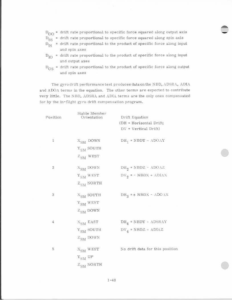
The gyro drift performancetest produces data on the N.B1D ., ADSR_A„ AMA
and ADOA terms in the equation- The other terms are expected to contribute
very little. The NBD, ADSRA and ADEA terms are the only ones compensated
for by the try-fli ght gyro drift con-spen5ation program.
Position Stable 'Member
Orientation Drift Equation
(DE = Horizontal Drift;
DV = Vertical Drift)
1 XiNt DOWN DR 1 NBDY - ADOAY
VS:A SOUTH
ZSM WEST
2 X m DOWN DH2
= NEDZ - ADO AZ
"i sm WEST - NBDX T AMAX
Z sm NORTH
3 Xs m SOUTH DH3
= N 11 DX - ADDAX
V4 EST
Zavi DOWN
4 Nsm EAST N ADSRAY
YS M
SOUTH DV 4 = N BD 7 - ADTAZ
Zs, m DOWN
5 N.sm WET No drift data for this position
SM UP
Zsm NORTH
1-48

Stable Member Position Orientation Drift Equation
6 Xsm SOUTH R o drift data for this position
Y DO '0;N
Zsm FA.ST
7 Xsria NORTH Dll7 -
-NBD\ - ADSRAX -- 2])0A£ -42
YSTA
UP- 1N [ST
zam UP-EAST
S
X SA1 "ST 3 = (-NBDZ NBDY )
UP-NORTH r1; - i\DIP1/411.
Z sm UP-SOUTH 112 (AWEINY ADSPLAZ)
2 X sm UP-EAST
S. m UP-WEST
H. zsm SOuT
1 DH — - N BUZ - — ADOAZ 9 v(2
10 K § .20 uP-NoRTI1 = - (NBTri• - io f- r./ 2
.y .SM u P-SOUTH -L12|4)UAY - -N.DTAYJ
Z sm F.' r I; 2 ( A.DoAy 9
X s:yi NORTH NBDX. = ADO.v.c.
T1/4.1 WEST
Zsm Up
19STA
UP DH N BDY + ADO
YSM
SOUTH
zsm EAST
X SIVI UP DEl i = NBDZ ADOAZ
sm E A.ST
Zsm

The equations for cornpensahle drift terms in 1e me the horizontal and
vertical drift measurements are
NBDX 1 2 (1)1I 3- DH
1 I)
N BD4 = 1 1 2 (DH DE 1 2 ) 1
NBDE = 1/2 mi-1 2 - ca-1 13 )
ADSRAX = DI-I 7 + 1/2 (DUI 3 - 13911)1 - (Min DH
3
ADSRA = D11 4 - 1 12 (D1-1 1
ADSHAZ N5 1D1-10, / Z D1I 2 D1113)1 (131 1-1 1 3
ADIAX = Dy 2 + 1 12 (DH 3 - DR
2 Dli I — 2 ADIAY 1 - 0 t 1
• DH 3 -1- D'i,r 2 - viaD1-1 7 -, (DU I -DS [ •
ADIAZ • WI - 1 12. (DH 2 . D1I 1 3 )
A WAX . - 1/2 (1.31-l i 1 - DI-1 3 ) (Not compensated)
ADOAY , 1/2 (DII19 - ml ! ) (Not compensated)
AWAZ • 1 i 2 (DII1 3
- Di12) (Not compensated)
27,3 Accelerometer scale Factor Error and .Bi•ad Error 1.) -..ita
The complete accelerometer model equation is
•
- pecific Force Indicated = AB AINF)I A P ('SF) P ;' (SF)Ci A II (51.1 12
A p(SF),(SF) AL ici (SF),(F)c , kpo(SF) 1 ,(SF/0
where subscriprts P. and 0 refer to input, pendulous and oqtput axes
respectively,
A B as coefficient, insensitive to specific forces
•A•i • scale factor of inRtrument
A PI A
•
cross coupling coefficients
specific force squared coefficient
• coefficient for the product of speLific force along m,7-r!
and pendulous axes
DR12'

A IO COefli eient for the product of specific force along input
aid output axes
P coefficient for the product of specific force along pendulous E.) and outpwt axes
The accelerometer test data are used to determine ❑ rth the bias Lind scale
factor coefficient's, Tne other terrnF are not prate rrteasured car
compensated.
The simplified equation for the accelerometer rn.06 ,A is7
Specific Force Indicated = Fii - Le Factor' ( Force .-long input axis )
The speQ.i.fic force used in the test is die zo the gravity redctiort .,:c-
celeration... The comparison of the incicated rriani -Ride of the gravity reaction
acceleration and the known: local gravity catihratton of tne au-
celerorne!..et._ The !-;nale factor error and taiay, are -:eparated by reversing the
direction of the pecific force alunrf the fripLit amts.
Forthe 7aLd.';', accelerornet.er the orients t:+ of the input u -ds parallel
to the dire.ction of local E rarity i ea.fiy accompli.4thee3 Ely 11,;E, of the data fr•an -,
the other two accelerometers.. For the Y accelerometer the Rirnbal1 configuration
does not allow acc:arrate positioning,. therefore data 7,.'2•onn the other two ac-
celerometers is used in the data analvsi5 to cni.ree!t. for :itput anti;-; alignment
L./ errors.
ti.talle :1/41ernOer Position Orientation \ccelerorneter Error Equation
si 7FIOCTII
Esm EAST
9 -_Ksm N g = FL'}(-g) -m2 x
Y sm WEST
Z sm NOBTII
xS• To Nowni'm 3 - (1 -
Y. WEST 11.
Z U P
•

4
5
6
X_ EAST
SOUTH
ZSM
DOWN
X 1 WEST
YSM UP
z66 NORTH
X SOUTH SDA
gm4 = 13 2.
g75 =. by +
grn6 =
" SFElt - gl
1-f-jT»+
- -SFE P( -
Y DOWN
EAST brd '
= Measured gravity reaction acceleration (cmi sec 2 ) calculated using ideal scale factor of 5.135 cm/sec/pulse
= local gravity reaction acceleration Cen9/9ec 2)
• as of i accelerometer (on-ilsec) i = x, y, z
= scale factor of laceelerometer in cm/sec/False
= scale factor error in parts-per-million defined as p.o.E.itive
v. ithen SF. > deal scale factor
Forpositions 5 and tithe misalignment angle 0 between the 'I accelerometer
and the veriical shall be determined from oulac• rate data.fram the other two
accelerometers.
(42
El -
(ayx - AV B ) SFx a z -
OT g local
(AV -z
) SF
AT g local
where AV number of velocity increments accumulated in AT
b_ AT B AV _ - 1
SF.

_grri5.6 will be modified by the misalignment 6 as follows:
gm5' = gm5 ec °v5
grn6 1 = gm6 sec ►v6
grn5 , and g rn5 . are used to determine Y accelerometerez.-tie factor and bias
error coefficients.
The equation for calculating scale factor error for the accelerometer is:
ISF E. = - grnj2 g loc
grn(ji-1) 6 ppm
al
The equation for determining hia, error for the accelerometer is:
g _ + g _ -ni m0 4- 1)
2 2
em/sec

Group 23A
COLOSSUS 2E
init.::: nal Di5t ribution
5_ 11,1.acDoull 1_ Brand P_ Brennan P. Chin J. Higgins P. Kachinar
IL-205 G. Levine E_ Muller C. Pu M. Reber W. Robertson
Group 2313 .1. Kaloostian A. Banc roft C, Heals N. Brodeur
Crocker .1. Goode R.. Haslarn
IL7-2211_. B. Ireland S. Jennings-J. Laird N. Neville W. Osianek R. Whittredgc
Group 23B
Group 2313
Group 23H
Group 23C
D. Lutkevi01 C. Babick G. Heck Vh. Danforth R. Daniel. F. D.E.:pain R. hates .1_ Flaherty J. Glendenning T. Good
Hubbard
C. N. L. A. M.
l•
D.
- 1- 2 ylai- 13arnert Brarn ley Ca•ier. Cramer Crowley Dem ery Densmore El Lassen Cntrel
Lynn S. Deutsch
Goldberger
M. Erickson R_ Bairnstather D. Fraser G. Kalan D. Keene
11_7 - 223
H. Navar .T. Reed (20) D. Reinke .T. B. Smith F. 1i. 1_11 -iarris P. 'IA oill
IL7-2211. M. Hamilton D. Hsiung E. Hughes D. Lollar S. Rosenberg P. aye N. Smith
IT 7-234A G. Kossuth ,T. O'Connor
ILli-102 A. Penchuk. R. Schlundt R. Stengel J. 'Turnbull

Group 2.3D
F. .1cGan G. Dirnock J_ Dunbar I_ Johnson R. Kiburz R. Metzinger E. OlszLort
Group 23D S. Prangley J. Nevin
1.1,7-332 R.. Schulte A. Sewall. S. Schroeder S. Smith F. I.Valh
IL7-2(19
12
2 Group 23P
Group 23P
Group 23P
Group 235
C. *1lER7 S. CopFiE
E. Johnson R. Ragan
✓ mArnsler U P. 1:e.ilernan Fl. McOuilt
[1_7-213 H. [mar-son
FLT 4. SimarneriF.
1.1_7-240. R.Strunce
▪ Werner R. WM»
Rubin L. Larson.
2
6
11 Group 23T
Group 23N
Grouo 33
Group 23P
APOLLO Library
MITI IL Library
a Farrell W. Day Gm Edrneand:; F, Gl'ace K. K .1. La-La:fence H. Lanes
G. Grover Em Blanchard
E. Johnson
J. fil-Arffrove I. Drane K. Glick.
J. Sutherland K. Greene
IL l2^ V. N1 _a. J. Reedy R. Suars J. Sliver J. St. Arrn:!-K.1
IL.11 -202 (T. T. Parr
11_7-111 1 3 , Mimno
11,7-2H tuhlr)
-1
4
2
D-2

F.'xternal Distribution List
MET instrumentation Laboratory
(5) I% 0_ Box 21025 Kennedy Space Center, Florida 32815 Attn: Mr. Ft. O'Donnell
MIT Instrumentation Lnhoratory
{31 Code EGi %HT Building 16 NASA Manned Spacecraft Canter Houston, Texas 77058 Attn: Mr. Thomas Lawton
NASA MSC H
0 01 Building M74-44.1!-1 Kennedy Space Center, FlOritia 32815 Attn: Mr. Frani-, HugneF
M r. A. Metz:7e r (N R AS PO at :411T IL) (3)
AC 17.1ectrot:icF (; E)
General Motors Corporation Milwaukee. Wisconsin Attn: Mr. dr Stridde 111c.4,p(, 32-33 Attn: Mr_ F. D.SF Mtn: Mr_ Siarnicki Dept 38-1- 12
KolL,•iman Instrument Corporation
( I) 575 Cridc.rhill Boulevard Syosset, Lon! Is:land Attn; Mr_ F. Nlet.oy
Raytheon C c.rrp p any
(43
Boston Post Poad Sudbury. MasFachuF;etts 01776 Attu: Mr. R. Zagrodnick
NASA; N1SFC
N AS A/ MSC
N atirmal Aertinautics :-4riri Space -'sdrnini George C. Marshall apace ContPt Huntsville. Nlabarna Attn: J. Mack R-AST1 -5 (1) Attn: V. Buckelew Se. E- G (1)
Deatan (i) Mo-o: e (1)
(1, Hosenthien E-AST11-1 . {I) I-700-E3 (1)
D_ Germany (1) R_ Barraza i-v-i: (1) W. Chubli (I) .1. N.lt-rCullouzit I- V r; (1)
National Aernnutico and Space .V1rniniration Manned Spacr.craft Center Apnllo 1)ocurnent Control Group (BM 86) Houston. Tex a5 771:15.13 Attn. .1. F:= .5 (letter of transtnittol only)
( i n)
300-1E

(6 I
(3/
{a)
Bellr.nr-nrn, I11. 111 17th 1-71treet Washington. 1),• , 21 11 o Attn: Info, Atnaly.:zi.. - Seelion
LINK LINK Group, 17411 A NA:if,, Boulevard
1.'e:,:as 77:F58 ..Attn... Mr, 11, I^lirtRE^ - U
THw 1 ,..lenie.ru,."fer Bidiz 1 .12 Holm, 71 , 45
Clne Space I',!.4-1 Redondo 1'Iir , .:ter -1. •:1027/t
N 1 (.13S National Space ldmirti tiatLun (2) (.1adcturd SpLacc , ("enter GreennOl, .Ittn; Code R13
C . ; A- (Irumnitr. (2}
rd.:q1-11:1a €.1,e, Nc.o. Vprk 11'714 \kiln; Mr. 3, (1
Attn: !,..1r. H, 1
N North Ann.,rit (I + EH}
[2214 I .A1;
a I-74!
1...111 ' 4.
NAR
N .ASqk
:%,1 :AS I 11 .14P(.1
N L's:-.;.Af111 1Q
(11 Lr•.- 'SERI! R ., • art Pi (J ., . are. L)f Fi:
['Tic f , ini
I :II-4
I --r, ,tc.s . -1- .11071 (3)
■ 1(11.1:-1
1, L , 7 ,11,..:1 4: CeiltUr. 1 lot 'I d a 32)10;1
.'tttn, Cou.trul C)ffict:
N \S .A. D'ily101.1i.1 1; I'
( 1 )
1'- ),BOK 25 , 11 , Dayton;t 2- lorida 321115 Attn: Mr. Lynian
.V -1 IleadepAar - n-rra
(6) riilll Endependanoe AvEqute
:isltine, LOD D. i .
\ttn: M \I'-2 AT_tn; r.--r tar, Code IMA
Attn:. 1 ,1ohn1't t_cre..0 \1
1] 4

A/1.1.=WIS
N ASA/ ync
N ASA/ LRC
N AHIKSC
A
'L i:WS:11R
Nations] 3e1. 0-riaLlLf. CS and spa.e Administration Lewis ReNeare:h Center ( teveland, (Thio Attn: Library
National lerenau -r,•ic... and Spnee \drniniF-tration Flight lie!Llei,i•7:-. Ce l ite j - Edw;Ards A1•1•., C.'atEforrii.a. ALif Lihrary
Nationa/ Aevorrautics and J..-ithaC•e AdtTliniyi.F;itinn 1%.m$!ey Research Centnt. Langley AFB. IrdnR Attn: Mr. A_ T. 'Mattson
Kennedy ';:.p.uirf.r Center, Florida 39815 m. S 0., B. North Arrpricar. Statfon . EK19 amp DprpiIrl matte
1,eronalotic.-; and :!-ipo.c.:Er• ArlmJni..ctration 111 Fiesitli.ni !.93pacenc•;ift [ 3 1 -oRi urn Officer (71r`urnrnn Aeroo.pace 1,1:1\1 Fiethp.affe, I -orig . I5.1ano. ••"•,.1-.0,' ¥ork 11714
2 .tiona.1 .. 1._erona.u•rus a d Space 'sihniniEtration (2) PePt ()ffice Drawer y),•1 I. CyuceN., Attn: Doi..._:rnentaten
(2)
tI