wheel‐rail interaction fundamentals · fundamentals kevin oldknow, ph ... – wear and rolling...
TRANSCRIPT

1
Wheel‐Rail Interaction Fundamentals
Kevin Oldknow, Ph.D., P.Eng.
2
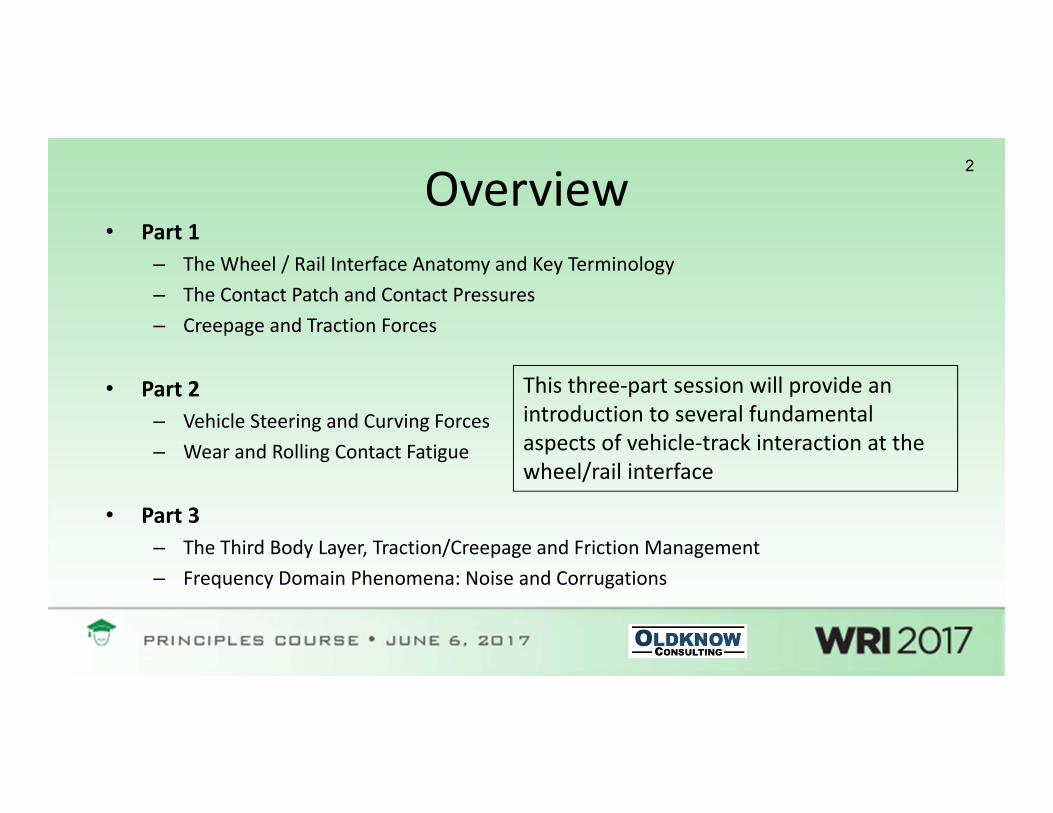
Overview• Part 1
– The Wheel / Rail Interface Anatomy and Key Terminology – The Contact Patch and Contact Pressures– Creepage and Traction Forces
• Part 2– Vehicle Steering and Curving Forces– Wear and Rolling Contact Fatigue
• Part 3– The Third Body Layer, Traction/Creepage and Friction Management– Frequency Domain Phenomena: Noise and Corrugations
This three‐part session will provide an introduction to several fundamental aspects of vehicle‐track interaction at the wheel/rail interface

3
Part 1
• The Wheel / Rail Interface Anatomy and Key Terminology
• The Contact Patch and Contact Pressures
• Creepage and Traction Forces

4
(Very) Basic Vehicle Running Gear Anatomy
• Wheels• Wheelsets• Axleboxes• Suspension• Frame

5
(Very) Basic Track Anatomy
• Rail• Crossties (Sleepers)• Tie Plates• Fasteners / Spikes & Anchors• Ballast• Subballast• Subgrade

6
• Tangent• Curve• Spiral• High Rail• Low Rail• Superelevation
(aka Cant)• Rail Cant
Recalling a few track geometry basics…

7The Wheel / Rail Interface and Key Terminology
Field Side Gage Side
Back of Flange (BoF)
Flange FaceFlange
RootAncillaryTread
Gage Face
Gage Corner
Mid‐GageBall / Crown / Top of Rail (TOR)
Back‐to‐Back Wheel Spacing
Track Gage

8The Wheel / Rail Interface and Key Terminology
(e.g. Low Rail Contact)“Lightly”Worn
“Heavily”Worn

9The Wheel / Rail Interface and Key Terminology
(e.g. High Rail Contact)
“Lightly”Worn
“Heavily”Worn

10
The Contact Patch and Contact Pressures
• Prep Question: What is the length of contact between a circle and a tangent line?
11
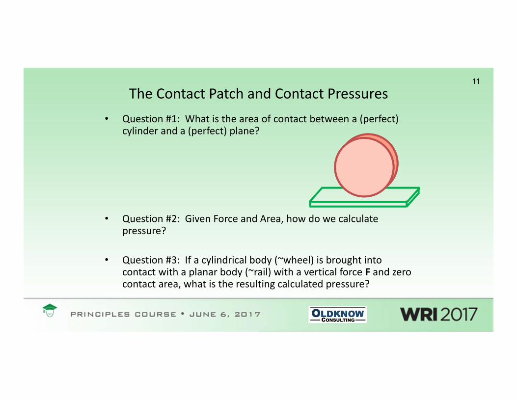
The Contact Patch and Contact Pressures• Question #1: What is the area of contact between a (perfect)
cylinder and a (perfect) plane?
• Question #2: Given Force and Area, how do we calculate pressure?
• Question #3: If a cylindrical body (~wheel) is brought into contact with a planar body (~rail) with a vertical force F and zero contact area, what is the resulting calculated pressure?

12Hertzian Contact• Hertzian Contact (1882) describes the pressures, stresses and deformations that
occur when curved elastic bodies are brought into contact.
• “Contact Patches” tend to be elliptical
• This yields parabolic contact pressures
• Contact theory was subsequently broadened to apply to rolling contact (Carter and Fromm) with non‐elliptical contact and arbitrary creepage (Kalker; more on this later…)
Pavg
Po=3/2Pavg

13
Creepage, Friction and Traction Forces• Longitudinal Creepage• The Traction‐Creepage Curve• Lateral Creepage• Spin Creepage• Friction at the Wheel‐Rail Interface

14Why is creepage at the Wheel/Rail Interface important?• Creepage at the wheel‐rail interface is fundamentally related to all
of the following (as examples):
– Locomotive adhesion– Braking– Vehicle steering– Curving forces– Wheel and rail wear– Rolling contact fatigue– Thermal defects– Noise– Corrugations

15
What does Longitudinal Creepagemean?...

16What does Longitudinal Creepagemean?...
• The frictional contact problem (Carter and Fromm, 1926) relates frictional forces to velocity differences between bodies in rolling contact.
• Longitudinal Creepage can be calculated as: Rω‐VV
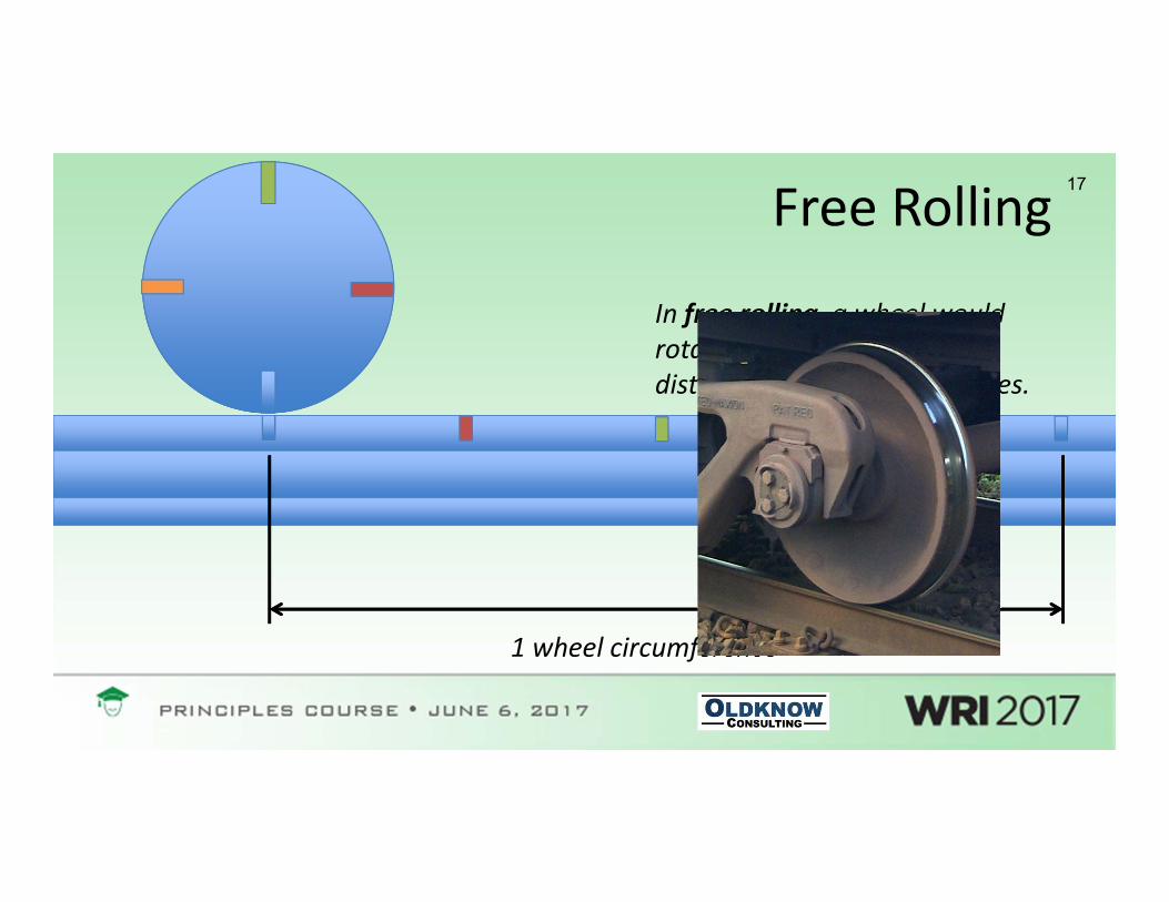
17Free Rolling
1 wheel circumference
In free rolling, a wheel would rotate 100 times to travel a distance of 100 circumferences.
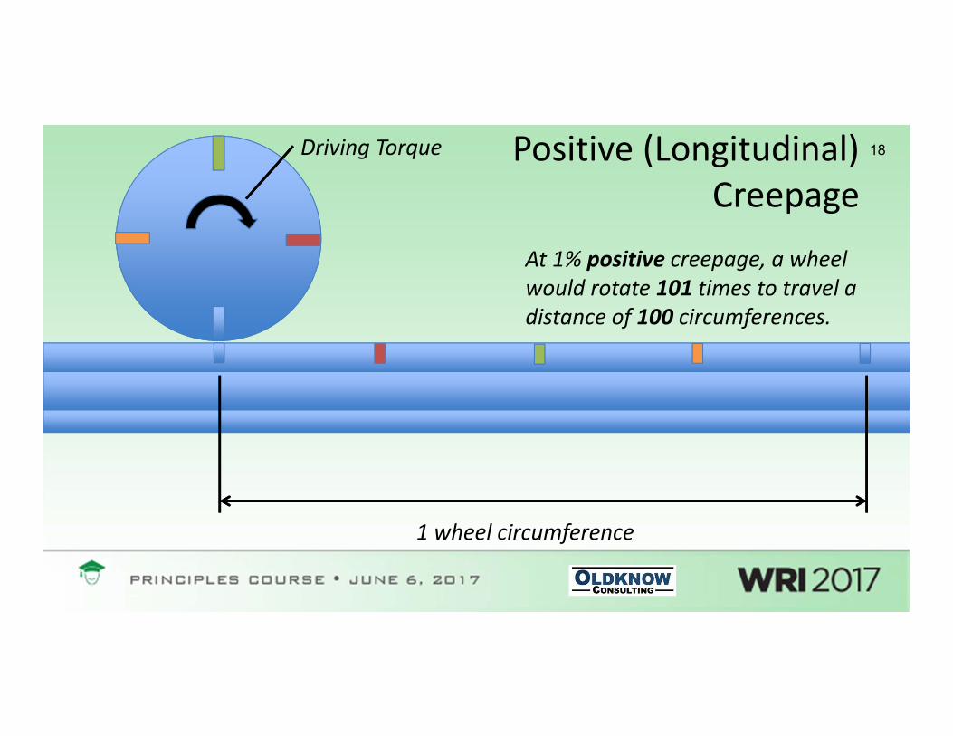
18Positive (Longitudinal) Creepage
1 wheel circumference
Driving Torque
At 1% positive creepage, a wheel would rotate 101 times to travel a distance of 100 circumferences.

19Negative (Longitudinal) Creepage
1 wheel circumference
Braking Torque
At 1% negative creepage, a wheel would rotate 99 times to travel a distance of 100 circumferences.
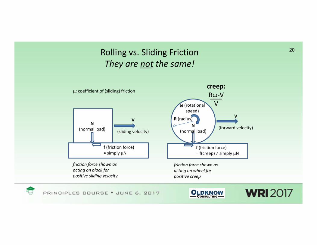
20Rolling vs. Sliding FrictionThey are not the same!
creep:Rω‐VV
R (radius)
ω (rotational speed)
V
(forward velocity)
V
(sliding velocity)N
(normal load)
N(normal load)
f (friction force)= f(creep) ≠ simply μN
f (friction force)≈ simply μN
friction force shown as acting on wheel for positive creep
friction force shown as acting on block for positive sliding velocity
μ: coefficient of (sliding) friction

21
The Traction‐Creepage Curve
µN
Longitudinal Creepage
Creep Force (Traction)
‐µN

22Lateral creepage
Imagine pushing a lawnmower across a steep slope…
OK, but when does this occur at the WRI?...

23Steering in “Steady State” Curving(“Mild” Curves)
23
Angle of Attack (AoA)

24Steering in “Steady State” Curving(“Sharp” Curves)
24
Angle of Attack (AoA)

25Steering in “Steady State” Curving(“Very Sharp” Curves)
25
Angle of Attack (AoA)

26Lateral Creepage
An angle of attack (AoA) of 0.57 degrees (0.01 Radians) corresponds to a lateral creepage of 1% at the leading wheelset.

27
A quick (sample) calculation…
Curve Radius, R
Wheelbase, 2L
Angle of Attack, α
V
α

28Spin CreepageThink of spinning a coin on a tabletop….
OK, but when does this occur at the WRI?...

29
Spin CreepageThe net creepage vector at the wheel/rail interface is (in general) a combination of longitudinal, lateral and spin.
Neutral (Free Rolling)
Slower (Braking)
Faster (Driving)

30The Wheelset and Steering Forces
Displacement (y)
longitudinal creep forces
r0r0
rR (> r0)rL (< r0)
Conicity (γ)
longitudinal traction/creepage
longitudinal traction/creepage

31Effective Conicity

32Effective Conicity (Worn Wheels)

33
Demonstration*: Steering forces in tangent track
* Wheel / rail demonstration rig, images and videos prepared by Josh Rychtarczyk

34Tangent Running and Stability
• Lateral displacement → ΔR mismatch→ friction forces→ steering moment
• Wheelset passes through central position with lateral velocity.
• At low speeds, oscillations decay.
• Above critical hunting speed, oscillations persist.
x
yz
displacement
forwardvelocity
longitudinal friction forces

35
Questions & Discussion
36
Part 2
• Vehicle Steering and Curving Forces
• Wear and Rolling Contact Fatigue

37Curving and Theoretical Equilibrium
Displacement (y)rR (> r0)
rL (< r0)
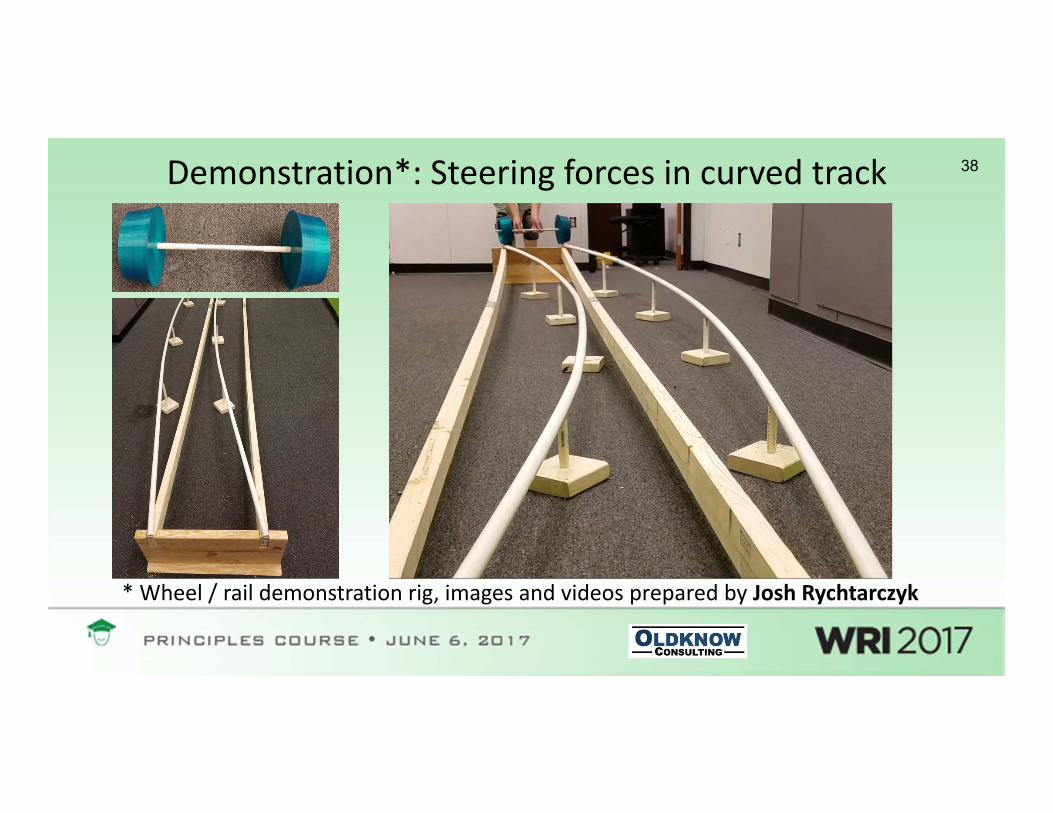
38Demonstration*: Steering forces in curved track
* Wheel / rail demonstration rig, images and videos prepared by Josh Rychtarczyk

Important Concept:
• Sometimes, forces give rise to creepage (e.g. traction, braking, steering)
• Other times, creepage gives rise to forces (e.g. curving)

40
Curving Forces (Two‐Axle Vehicle, Sharp Curve)
40
Angle of Attack (AoA)
Trailing Axle, Low Rail:R > Requilibrium→ Posi ve Longitudinal Creepage→ Longitudinal Creep Force
Trailing Axle, High Rail:R < Requilibrium→ Nega ve Longitudinal Creepage→ Longitudinal Creep Force
Leading Axle, Low Rail:Angle of Attack→ Primarily Lateral Creepage→ Lateral Creep Force
Leading Axle, High Rail (Tread):Angle of Attack→ Primarily Lateral Creepage→ Lateral Creep Force
Leading Axle, High Rail (Flange):R >> Requilibrium→ Posi ve Longitudinal Creepage→ Longitudinal Creep ForcePlus:Normal force (keeps vehicle on track)
Reaction Forces (felt by track)

41Impacts of High Lateral Loads:
Rail Rollover / Track Spread Derailments

42Impacts of High Lateral Loads:Plate Cutting, Gauge Widening

43Impacts of High Lateral Loads:Wheel Climb Derailments
0
0.5
1
1.5
2
2.5
3
3.5
55 60 65 70 75 80 85
Flange Angle (Degrees)L
ater
al/V
ertic
al F
orce 0.1
0.20.30.40.50.60.7
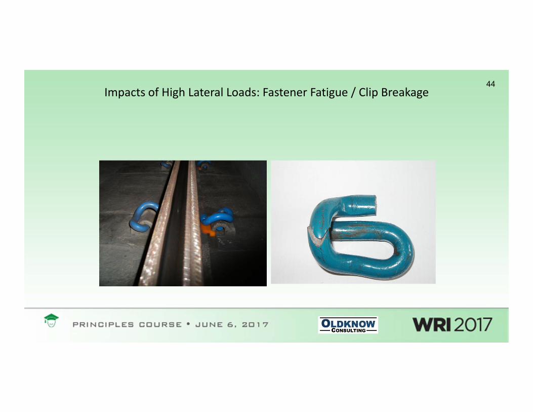
44Impacts of High Lateral Loads: Fastener Fatigue / Clip Breakage
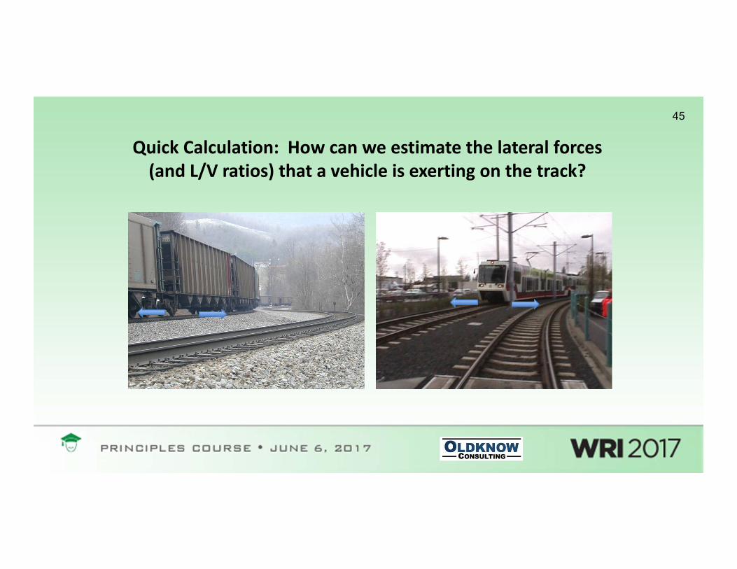
45
Quick Calculation: How can we estimate the lateral forces (and L/V ratios) that a vehicle is exerting on the track?

46Estimating AoA and Lateral Creepage in a “Sharp” Curve
Curve Radius, R
Wheelbase, 2L
Angle of Attack, α
V
• Leading Axle angle of attack:α ~ arcsin(2L/R) ~ 2L/R = 0.0061 Rad (6.1 mRad)
• Lateral Creepage at TOR contact:Vlat/V ~ 2L/R ~ α = 0.61%
α
• Example:6o curve (R = 955’)70” wheelbase (2L = 5.83’)μTOR = 0.5 (dry)

47Estimating Low Rail L/V and Lateral Force
L/V
Creep
μAt high creep L/V ~ μ
At low creep L/V ~ const*creep
~1(%)
Angle of Attack (AoA)
• At 0.61% creep:L/V = ______ μ

48How does this compare with simulation results?
48
‐0.10
0.00
0.10
0.20
0.30
0.40
0.50
0 50 100 150 200 250
VAMPIRE® Simulation: Low Rail L/V6o curve (R=955'), SE = 3.9", Speed = 30mph, μTOR=0.5, μGF=0.15
Axle 1 LR L/V Axle 2 LR L/V Axle 3 LR L/V Axle 4 LR L/V

Other Factors Affecting Curving Forces
• Creepage and friction at the gage face / wheel flange interface
• Speed (relative to superelevation) and centrifugal forces
• Coupler Forces (e.g. Buff & Drag)
• Vehicle / Track Dynamics:– Hunting– Bounce– Pitch– Roll

50
Rail and Wheel Wear

Rail and Wheel Wear
c proportional to COF
N
l
HNlcV • “Archard” Wear Law:
– V = volume of wear– N = normal load– l = sliding distance (i.e. creepage)– H = hardness– c = wear coefficient
• Wear Types:– Adhesion– Surface Fatigue– Abrasion– Corrosion– Rolling Contact Fatigue– Plastic Flow

52
Wear regimes
T = Tractive forceү = Slip

53
Shakedown and Rolling Contact Fatigue (RCF)
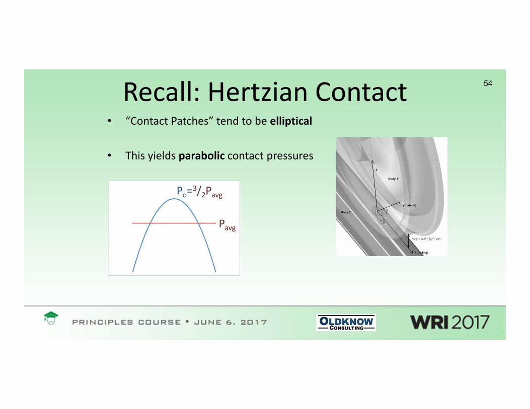
54Recall: Hertzian Contact• “Contact Patches” tend to be elliptical
• This yields parabolic contact pressures
Pavg
Po=3/2Pavg

55The Contact Patch and Contact Pressures

56The Contact Patch and Contact Pressures
Low Rail Contact Area, mm2

57Example calculation: Average and Peak Pressure
• Let’s assume a circular contact patch, with a radius of 0.28” (7 mm)• The contact area is then: 0.24 in2 (154 mm2)• Assuming a HAL vehicle weight (gross) of 286,000 lbs, we have a nominal wheel load
of 35,750 lbs, i.e. 35.75 kips (159 kN)• The resulting average contact pressure (Pavg) is then: 150 ksi (1,033 MPa)• This gives us a peak contact pressure (Po) of: 225 ksi (1,550 MPa)
• What is the shear yield strength of rail steel?*• What’s going on?
*Magel, E., Sroba, P., Sawley, K. and Kalousek, J. (2004) Control of Rolling Contact Fatigue of Rails, Proceedings of the 2004 AREMA Annual Conference, Nashville, TN, September 19‐22, 2004
Steel Hardness(Brinnell)
K
ksi MPa
“Standard” 260‐280 65‐70 448‐483
“Intermediate” 320‐340 80‐85 552‐587
“Premium” 340‐380 85‐95 587‐656
“HE Premium” 380‐400 95‐100 656‐691

58
Tensile Testing (1‐D loading) Spherical Contact with Elastic Half‐Space (3‐D loading)
Cylindrical Contact with Elastic Half‐Space (2‐D loading)
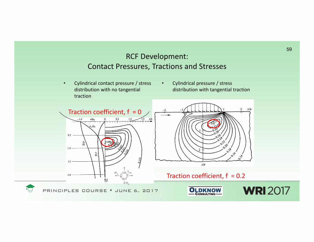
59RCF Development:
Contact Pressures, Tractions and Stresses
• Cylindrical contact pressure / stress distribution with no tangential traction
• Cylindrical pressure / stress distribution with tangential traction
zx
z
xzx
z
x
Traction coefficient, f = 0
Traction coefficient, f = 0.2

60RCF Development: Shakedown
Reduced Stress(e.g. wheel/rail profiles)
Increased Material Strength
Reduced Traction Coefficient(e.g. reduced friction)
0 0,1 0,2 0,3 0,4 0,5 0,6
1
2
3
4
5
6
7
traction coefficient T/N
load
factor
plasticshakedown
elastic shakedown
elastic
ratchetting
subsurface surface
p0/ke

61
61

62

63
Hydropressurization: effect of liquids on crack growth

64
Question: How can we determine if there is a risk of rolling contact fatigue (RCF) developing under a given
set of vehicle/track conditions?

65• Consider a heavy haul railway site, where heavy axle load vehicles (286,000 lb gross weight) with a typical wheelbase of 70” traverse a 3 degree curve at balance speed.
• Wheel / rail profiles and vehicle steering behavior are such that the curve can be considered “mild”
• The contact area at each wheel tread / low rail interface is approximately circular, with a typical radius of 7mm.
• The rail steel can be assumed to have a shear yield strength of k=70 ksi.
• The rail surface is dry, with a nominal COF of μ = 0.6
• How would you assess the risk of low rail RCF formation and growth under these conditions?
65

66Estimating lateral creepage, traction ratio & contact pressure:
• In “mild” curving, leading axle angle of attack:α ~ arcsin(L/R) ~ L/R = 0.0030 Rad (3.0 mRad)
• Lateral Creepage at low rail TOR contact:Vlat/V ~ 2L/R ~ α = 0.3%
66
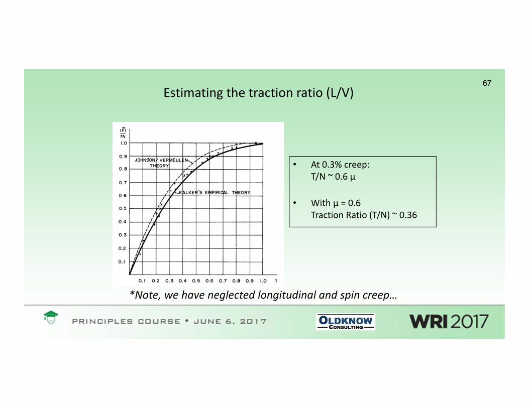
67Estimating the traction ratio (L/V)
• At 0.3% creep:T/N ~ 0.6 μ
• With μ = 0.6Traction Ratio (T/N) ~ 0.36
*Note, we have neglected longitudinal and spin creep…

68Where are we on the shakedown map?
0 0,1 0,2 0,3 0,4 0,5 0,6
1
2
3
4
5
6
7
traction coefficient T/N
load
factor
plasticshakedown
elastic shakedown
elastic
ratchetting
subsurface surface
p0/ke
• From the previous slide T/N ~0.36
• We previously calculated Po = 225 ksi
• With K = 70ksi,Po/K = 3.21

69
Questions & Discussion

70
Part 3
• The Third Body Layer, Traction/Creepage and Friction Management
• Frequency Domain Phenomena: Noise and Corrugations

71
“Free Rolling”
Wheel
Rail
Third Body Layer
Rω=V• Third Body Layer
is made up of iron oxides, sands, wet paste, leaves etc….

72“Small” Positive (Longitudinal)
Creepage
Wheel
Rail
Third Body Layer
Rω>V
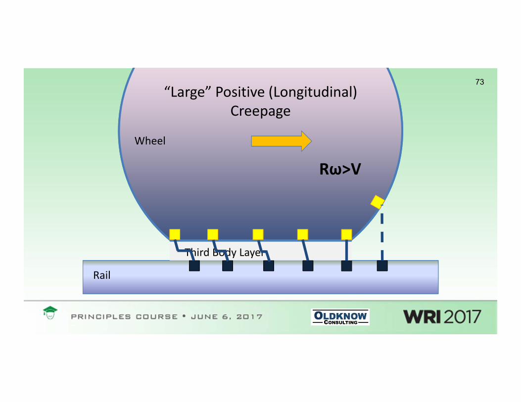
73“Large” Positive (Longitudinal)
Creepage
Wheel
Rail
Third Body Layer
Rω>V

74
The Traction‐Creepage Curve
Rolling Direction
µN
AdhesionMicroslip
Longitudinal Creepage

75Traction/Creepage Curves

76
Third Body Layer – Micron Scale
Y.Berthier, S. Decartes, M.Busquet et al. (2004). The Role and Effects of the third body in the wheel rail interaction. Fatigue Fract. Eng. Mater Struct. 27, 423‐436
Rail Wheel

77
Friction Management
78
Key Points• The third body layer accommodates velocity differences between the
wheel and rail (i.e. creepage)
• Friction forces are determined by the shear properties of the third body layer and its response to shear displacement (creepage)
• Friction management is the intentional manipulation of the shear properties of the third body layer.

79
Managing friction: two distinct interfaces
1. Gauge Face / Wheel Flange Lubrication
2. Top of Rail / Wheel Tread Friction Control

80Controlling Friction at the Wheel/Rail Interface
Top of Rail (TOR) Friction Impacts:- Lateral Forces- Rail / Wheel Wear (TOR, Tread)- RCF Development- Fuel Efficiency- Squeal Noise - Flange Noise (indirect)- Corrugations- Hunting- Derailment Potential
(L/V, rail rollover)
Gage Face (GF) Friction Impacts:- Rail / Wheel Wear (Gage Face, Flange)- RCF Development- Fuel Efficiency- Flange Noise- Derailment Potential (Wheel Climb)- Lateral Forces (indirect)

81
Ideal Targets
Low rail High Rail
<0.2TOR: =0.3-0.35TOR: =0.3-0.35

82
Friction Management Approaches
Applications
Trackside Mobile
GF Lubrication
TOR Friction Modifiers
Gauge/Flange TOR/Tread
Liquid/SolidLubrication
Liquid/SolidFriction
Modifiers

83TracksideGage Face Lubrication

84

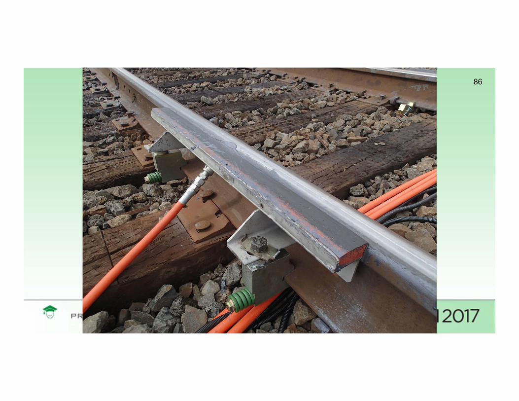
85
Trackside Top of RailFriction Control
86
87
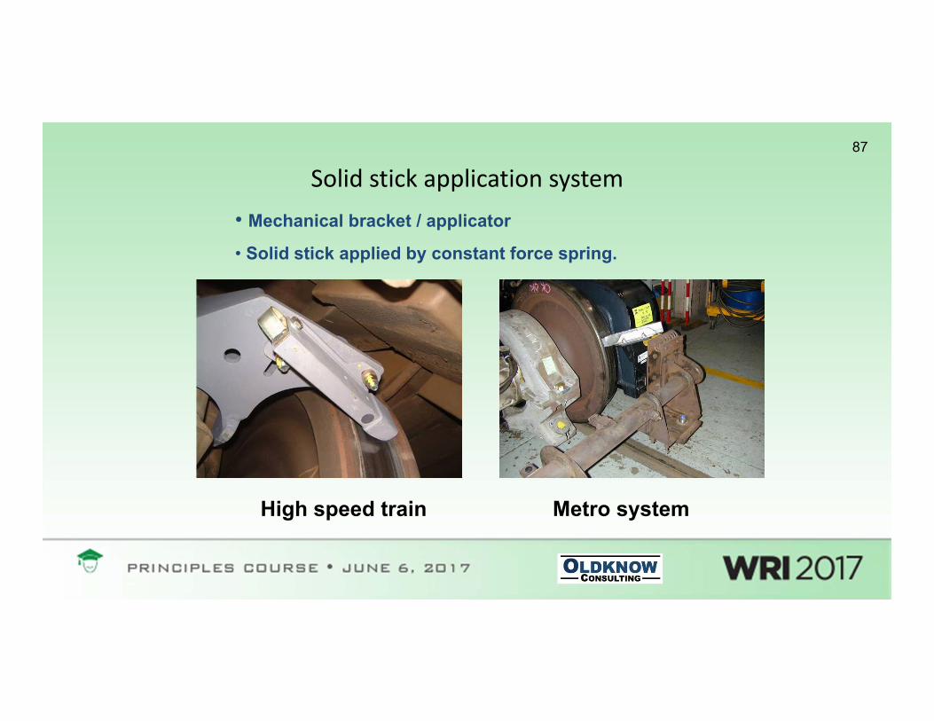
Solid stick application system
High speed train Metro system
• Mechanical bracket / applicator
• Solid stick applied by constant force spring.

88
Mobile (Car Mounted) Top of Rail Friction Management

89Mobile Gage Face Lubrication(or Top of Rail Friction Control)Hi‐Rail Mounted Delivery Systems

90Maximizing system performance
• Critical areas to address include:
– Assessment and Implementation of Solutions
– Keeping units filled with lubricants / friction modifiers
– Ensuring adequate year‐round power supply & charging
– Efficient removal / reinstallation to accommodate track programs
– Proactive Maintenance / Efficient response to equipment damage

91
Example: Friction Management impacts on Curving Forces
91
Angle of Attack (AoA)
GF Lubrication:Reduction in COF at GF/Flange→ Reduc ons in wear and energyBut: Reduction in Longitudinal Creep Force and Positive Steering Moment→ Small increase in AoA and Lateral Forces
TOR Friction Control:Reduction in COF at TOR/Tread→ Reduc ons in TOR/Tread Creep Forces and Negative Steering Moments→ Reduc ons in Lateral Forces, Wear, Energy, etc.

92Example: Friction Management, Wear and RCF wheel/rail rig test results
2,042,00
1,00
1,77
0,000,501,001,502,002,50
crack depth [mm] crack distance [mm]
dist
ance
[mm
]
R260R350HT
newdry
FM 100kFM 400k
newdry
FM 100kFM 400k
R260 R350HT
Dry tests crack results
93
Curving Noise

94Spectral range for different noise types
Noise type Frequency range, Hz
Rolling 30 -2500
Rumble (including corrugations) 200 - 1000
Flat spots 50 -250 (speed dependant)
Ground Borne Vibrations 30 - 200
Top of rail squeal 1000 - 5000
Flanging noise 5000 – 10000

95Top of rail wheel squeal noise
• High pitched, tonal squeal (predominantly 1000 – 5000 Hz)• Prevalent noise mechanism in “problem” curves, usually < 300m
radius• Related to both negative friction characteristics of Third Body at
tread / top of rail interface and absolute friction level Stick-slip oscillations
Flanging noise• Typically a “buzzing” OR “hissing” sound, characterized by
broadband high frequency components (>5000 Hz)• Affected by:
• Lateral forces: related to friction on the top of the low rail• Flanging forces: related to friction on top of low and high
rails • Friction at the flange / gauge face interface

96The Traction‐Creepage Curve:Positive (Rising) and Negative (Falling) Friction
Creepage
Creep ForceNeutral Friction
Positive (Rising) Friction
Negative (Neutral) Friction
Creep Saturation

97Absolute Friction Levels and Positive/Negative Friction
0.00
0.10
0.20
0.30
0.40
0.50
0.0 0.2 0.4 0.6 0.8 1.0 1.2 1.4
Creep Rate (%)
Y/Q
* Replotted from: “Matsumoto a, Sato Y, Ono H, Wang Y, Yamamoto Y, Tanimoto M & Oka Y, Creep force characteristics
between rail and wheel on scaled model, Wear, Vol 253, Issues 1-2, July 2002, pp 199-203
“Negative” or “Falling” friction
“Positive” or “Rising” friction
Dry Contact
Friction Modifier+
++
‐‐
‐
Creepage / friction force
Stick-slip limit cycle

98Sound spectral distribution for different wheel / rail systems
0.0
20.0
40.0
60.0
80.0
100.0
12.5
31.5 80 200
500
1250
3150
8000
Frequency [Hz]
Soun
d Pr
essu
re [d
B
Freight 1 Freight 2
Metro 1 Metro 2
Tram 1 Tram 2
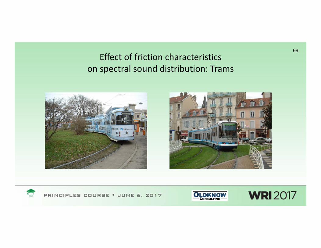
99Effect of friction characteristics
on spectral sound distribution: Trams

100Effect of friction characteristics
on spectral sound distribution: Trams
0.0
20.0
40.0
60.0
80.0
100.0
12.5
31.5 80 200
500
1250
3150
8000
Frequency (Hertz)
Soun
d L
evel
(dBA
Baseline Friction Modifier

101“Low Frequency” Stick‐Slip / Noise
101
* Video used with permission, Brad Kerchof, Norfolk Southern

102
Corrugations (Short Pitch)

103
Perturbation DamageMechanism
WavelengthFixing
Mechanism
Corrugation formation: common threads
+Corrugations

104

105
Pinned‐Pinned corrugation (“roaring rail”)
• At the pinned‐pinned resonance, rail vibrates as it were a beam almost pinned at the ties / sleepers
• Highest frequency corrugation type: 400 – 1200 Hz• Modulation at tie / sleeper spacing – support appears dynamically stiff
so vertical dynamic loads appear greater

106
Rutting•Typically appears on low rail
•Frequency corresponds to second torsionalresonance of driven wheelsets
•Very common on metros
•Roll‐slip oscillations are central to mechanism
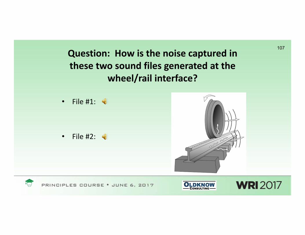
107Question: How is the noise captured in these two sound files generated at the
wheel/rail interface?
• File #1:
• File #2:

108Summary• Returning to our objectives, we have reviewed:
– The Wheel / Rail Interface and Key Terminology– The Contact Patch and Contact Pressures– Creep, Traction Forces and Friction– Wheelset Geometry and Effective Conicity– Vehicle Steering and Curving Forces– Wheel and Rail Wear Mechanisms – Shakedown and Rolling Contact Fatigue– The Third Body Layer, Traction/Creepage and Friction Management– Curving Noise– Corrugation
• The intent has been to establish a framework to understand, articulate, quantify and identify key phenomena that affect the practical operation, economics and safety of heavy haul and passenger rail systems.

109
Questions & Discussion