what electrons can tell us about metals
TRANSCRIPT

What Electrons Can Tell Us About MetalsC. J. Davisson Citation: Journal of Applied Physics 8, 391 (1937); doi: 10.1063/1.1710312 View online: http://dx.doi.org/10.1063/1.1710312 View Table of Contents: http://scitation.aip.org/content/aip/journal/jap/8/6?ver=pdfcov Published by the AIP Publishing Articles you may be interested in What the eyes can tell us about spokenlanguage comprehension. J. Acoust. Soc. Am. 124, 2472 (2008); 10.1121/1.4808942 What can binocular rivalry tell us about auditory streaming J. Acoust. Soc. Am. 123, 3053 (2008); 10.1121/1.2932767 What physical acoustics can tell us about fluids J. Acoust. Soc. Am. 94, 1857 (1993); 10.1121/1.407670 What “tips of the slung” can tell us about the production and comprehension of speech J. Acoust. Soc. Am. 55, S42 (1974); 10.1121/1.1919704 What Geodosy Can Tell Us About Immediate and Ultimate Causes of Earthquake J. Appl. Phys. 14, 104 (1943); 10.1063/1.1714958
[This article is copyrighted as indicated in the article. Reuse of AIP content is subject to the terms at: http://scitation.aip.org/termsconditions.
Downloaded to ] IP: 132.174.255.116 On: Sat, 20 Dec 2014 21:54:47
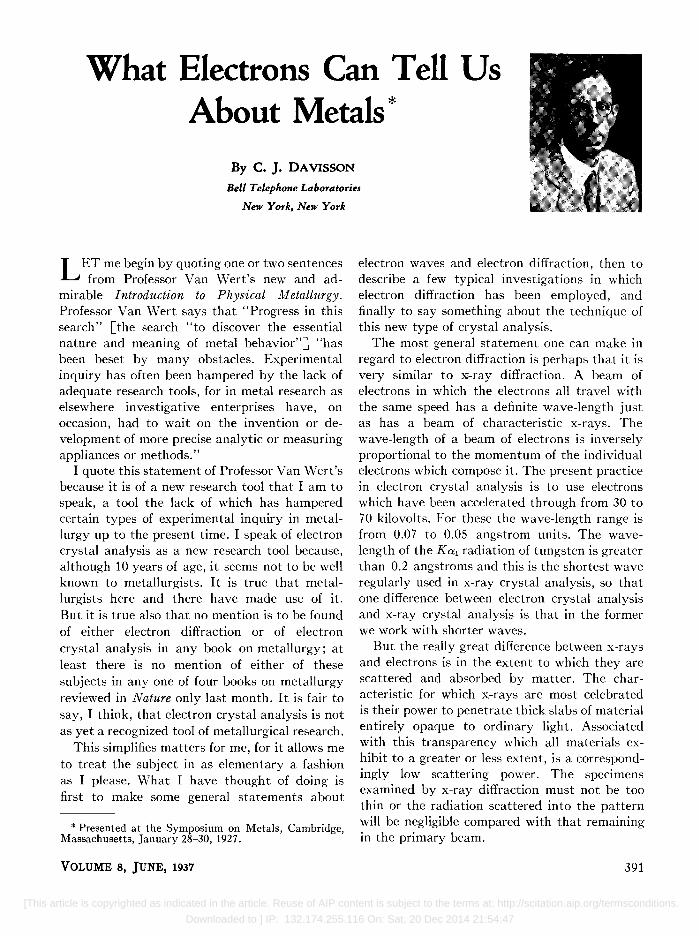
What Electrons Can Tell Us About Metals *
By C. J. DAVISSON
Bell Telephone Laboratories
New York, N~w York
L ET me begin by quoting one or two sentences from Professor Van Wert's new and ad
mirable Introduction to Physical Metallurgy. Professor Van Wert says that "Progress in this search" [the search "to discover the essential nature and meaning of metal behavior"] "has been beset by many obstacles. Experimental inquiry has often been hampered by the lack of adequate research tools, for in metal research as elsewhere investigative enterprises have, on occasion, had to wait on the invention or development of more precise analytic or measuring appliances or methods."
I quote this statement of Professor Van Wert's because it is of a new research tool that I am to speak, a tool the lack of which has hampered certain types of experimental inquiry in metallurgy up to the present time. I speak of electron crystal analysis as a new research tool because, although 10 years of age, it seems not to be well known to metallurgists. It is true that metallurgists here and there have made use of it. But it is true also that no mention is to be found of either electron diffraction or of electron crystal analysis in any book on metallurgy; at least there is no mention of either of these subjects in anyone of four books on metallurgy reviewed in Nature only last month. It is fair to say, I think, that electron crystal analysis is not as yet a recognized tool of metallurgical research.
This simplifies matters for me, for it allows me to treat the subject in as elementary a fashion as I please. What I have thought of doing is first to make some general statements about
* Presented at the Symposium on Metals, Cambridge, Massachusetts, January 28-30,1927.
VOLUME 8, JUNE, 1937
electron waves and electron diffraction, then to describe a few typical investigations in which electron diffraction has been employed, and finally to say something about the technique of this new type of crystal analysis.
The most general statement one can make in regard to electron diffraction is perhaps that it is very similar to x-ray diffraction. A beam of electrons in which the electrons all travel with the same speed has a definite wave-length just as has a beam of characteristic x-rays. The wave-length of a beam of electrons is inversely proportional to the momentum of the individual electrons which compose it. The present practice in electron crystal analysis is to use electrons which have been accelerated through from 30 to 70 kilovolts. For these the wave-length range is from 0.07 to 0.05 angstrom units. The wavelength of the Kal radiation of tungsten is greater than 0.2 angstroms and this is the shortest wave regularly used in x-ray crystal analysis, so that one difference between electron crystal analysis and x-ray crystal analysis is that in the former we work with shorter waves.
But the really great difference between x-rays and electrons is in the extent to which they are scattered and absorbed by matter. The characteristic for which x-rays are most celebrated is their power to penetrate thick slabs of material entirely opaque to ordinary light. Associated with this transparency which all materials exhibit to a greater or less extent, is a correspondingly low scattering power. The specimens examined by x-ray diffraction must not be too thin or the radiation scattered into the pattern will be negligible compared with that remaining in the primary beam.
391
[This article is copyrighted as indicated in the article. Reuse of AIP content is subject to the terms at: http://scitation.aip.org/termsconditions.
Downloaded to ] IP: 132.174.255.116 On: Sat, 20 Dec 2014 21:54:47
a
b
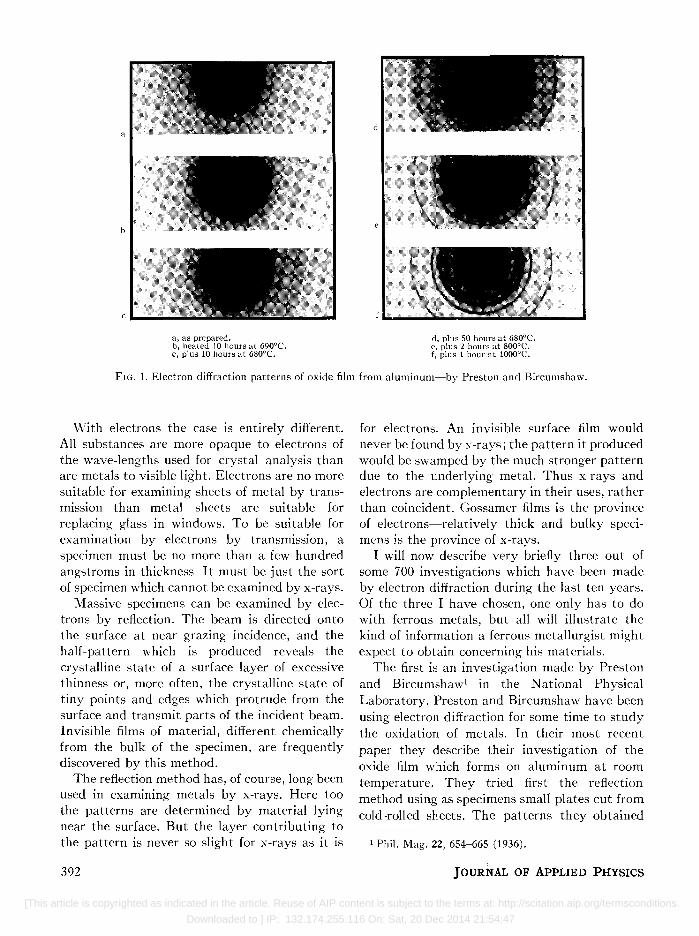
a, as prepared. b, heated 10 hours at 690°C. c, plus 10 hours at 680°C.
d, plus 50 hours at 680°C. e, plus 2 hours at 800°C. f, plus 1 hour at 1000oC.
FIG. 1, Electron diffraction patterns of oxide film from aluminum-by Preston and Bircumshaw.
\Vith electrons the case is entirely different. All substances are more opaque to electrons of the wave-lengths used for crystal analysis than are metals to visible light. Electrons are no more suitable for examining sheets of metal by transmission than metal sheets are suitable for replacing glass in windows. To be suitable for examination by electrons by transmission, a specimen must be no more than a few hundred angstroms in thickness It must be just the sort of specimen which cannot be examined by x-rays.
Massive specimens can be examined by electrons by reflection. The beam is directed onto the surface at near grazing incidence, and the half-pattern which is produced reveals the crystalline state of a surface layer of excessive thinness or, more often, the crystalline state of tiny points and edges which protrude from the surface and transmit parts of the incident beam. Invisible films of material, different chemically from the bulk of the specimen, are frequently discovered by this method.
The reflection method has, of course, long been used in examining metals by x-rays. Here too the patterns are determined by material lying near the surface. But the layer contributing to the pattern is never so slight for x-rays as it is
392
for electrons. An invisible surface film would never be found by x-rays; the pattern it produced would be swamped by the much stronger pattern due to the underlying metal. Thus x-rays and electrons are complementary in their uses, rather than coincident. Gossamer films is the province of electrons-relatively thick and bulky specimens is the province of x-rays.
I will now describe very briefly three out of some 700 investigations which have been made by electron diffraction during the last ten years. Of the three I have chosen, one only has to do with ferrous metals, but all will illustrate the kind of information a ferrous metallurgist might expect to obtain concerning his materials.
The first is an investigation made by Preston and Bircumshaw1 in the National Physical Laboratory. Preston and Bircumshaw have been using electron diffraction for some time to study the oxidation of metals. In their most recent paper they describe their investigation of the oxide film which forms on aluminum at room temperature. They tried first the reflection method using as specimens small plates cut from cold ·rolled sheets. The patterns they obtained
1 Phil. Mag. 22, 654-665 (1936).
JOURNAL OF ApPLIED PHYSICS
[This article is copyrighted as indicated in the article. Reuse of AIP content is subject to the terms at: http://scitation.aip.org/termsconditions.
Downloaded to ] IP: 132.174.255.116 On: Sat, 20 Dec 2014 21:54:47
consisted of portions of two broad fuzzy rings such as are produced when x-rays are diffracted by a liquid. This might mean that the oxide formed on aluminum at room temperature is amorphous, or it might mean that the surface metal had been rendered amorphous by the rolling and that the pattern was due to the metal rather than to the oxide. To dispose of this uncertainty Preston and Bircumshaw dissolved away thin sheets of aluminum by gaseous HCI, leaving only the oxide films. These they examined by transmission and again they found the broad fuzzy rings. The oxide film formed on cold-rolled aluminum at room temperature is undoubtedly amorphous.
On heating, the film remains amorphous to about 700°C at which temperature a pattern of sharp rings begins forming. When fully formed the pattern is that of 'Y-AI 20 a. It is identical with the pattern produced by oxide films fished from molten aluminum. Patterns obtained at various stages of the transition from amorphous to crystalline oxide are reproduced in Fig. 1. There are certain peculiarities about the early stages of the crystallization, as revealed by the patterns, which are not yet understood.
face after abrasion-more specifically, after the face had been smoothed by filing. The results which Dr. Germer obtained are perhaps of some interest to metallurgists because of a similarity between what happens when a galena crystal is filed, and what happens when a metal is hardened by cold working.
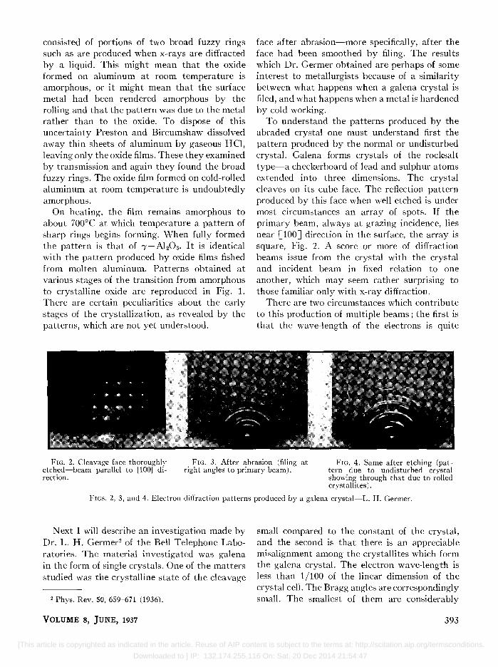
To understand the patterns produced by the abraded crystal one must understand first the pattern produced by the normal or undisturbed crystal. Galena forms crystals of the rocksalt type-a checkerboard of lead and sulphur atoms extended into three dimensions. The crystal cleaves on its cube face. The reflection pattern produced by this face when well etched is under most circumstances an array of spots. If the primary beam, always at grazing incidence, lies near [100J direction in the surface, the array is square, Fig. 2. A score or more of diffraction beams issue from the crystal with the crystal and incident beam in fixed relation to one another, which may seem rather surprising to those familiar only with x-ray diffraction.
There are two circumstances which contribute to this production of multiple beams; the first is that the wave-length of the electrons is quite
FIG. 2. Cleavage face thoroughly etched-beam parallel to [100] direction.
FIG. 3. After abrasion (filing at right angles to primary beam).
FIG. 4. Same after etching (pattern due to undisturbed crystal showing through that due to rolled crystallites) .
FIGS. 2, 3, and 4. Electron diffraction patterns produced by a galena crystal-L. H. Germer.
N ext I will describe an investigation made by Dr. L. H. Germer2 of the Bell Telephone Laboratories. The material investigated was galena in the form of single crystals. One of the matters studied was the crystalline state of the cleavage
2 Phys. Rev. 50, 659-671 (1936).
VOLUME 8, JUNE, 1937
small compared to the constant of the crystal, and the second is that there is an appreciable misalignment among the crystallites which form the galena crystal. The electron wave-length is less than 1/100 of the linear dimension of the crystal cell. The Bragg angles are correspondingly small. The smallest of them are considerably
393
[This article is copyrighted as indicated in the article. Reuse of AIP content is subject to the terms at: http://scitation.aip.org/termsconditions.
Downloaded to ] IP: 132.174.255.116 On: Sat, 20 Dec 2014 21:54:47

smaller than the largest angles by which the crystallites fail of perfect alignment. In these circumstances Bragg reflections of differing indices can occur from different crystallites for one and the same setting of beam and crystal. This is an explanation, though not the only possible explanation, of the spot pattern observed in this case. For present purposes we need know only that this square array of spots is the pattern produced by the cleavage face of the undisturbed crystal when the incident beam is parallel to a cube edge direction, or nearly so.
The crystal face was then abraded-filed parallel to a [100J direction. In this condition it produced a pattern of rings, Fig. 3. The surface material had been broken up and skewed
/ UNDISTURBED CRYSTAL
SPOT PATTERN
\
----i0:l: 10.
I DIRECTION OF F'lLING
BROKEN UP - .... ATERIAL --RING PATTERN
ROLLED CRYSTALLITES ARC PATTERN
FIG. 5. Schematic cross section of a galena crystal illustrating the deformation produced by abrasion.
about into random orientations. What was observed was the powder pattern of galena.
The surface of the crystal was then etched away a little at a time, and the pattern recorded at each stage of the etching. \Vhat was observed depended upon the relation between the direction of the primary beam and the direction of filing. When the direction of the primary beam was at right angles to the direction of filing the ring pattern weakened, some of the rings vanished completely and others were reduced to short arcs. This pattern of arcs, which exhibited no recognizable symmetry, persisted without alteration through some stages of etching. Then the square array of spots began showing through, indicating that undisturbed crystal was beginning to outcrop, Fig. 4. When this occurred it was discovered that each of the arcs was associated with one of the spots, and that the arc pattern
394
could be described as a rotation and streaking out of the spot pattern. It was as if the crystallites in a layer immediately below the surface had been rolled by the file through angles ranging from 10 to 30 degrees, and this undoubtedly is what had happened.
The behavior is illustrated in Fig. 5. The drawing represents a cross section of the crystal after filing, the direction of filing being downward. The surface layer is badly broken up and disorganized and produces the ring pattern. Below this is a relatively thick layer in which the crystallites, represented as blocks, have been rolled by the file. They roll from 10 to 30 degrees and then jam. The materiai in this layer produces the arc pattern. Below this is the undisturbed material which produces the spot pattern. This exemplifies rather well one of the actions which is known from x-ray analysis to occur in work hardening.
The last experiment I will describe is by Dr. H. R. Nelson3 of the Battelle Institute. Dr. Nelson has vaporized iron onto flat surfaces in vacuum and has studied the patterns produced by these deposits before and after exposure to air. One of these is reproduced in Fig. 6. Most of the spots or short arcs of this pattern fall on equally spaced lines parallel to the surface of the specimen. These alone are due to the iron and what they reveal is that the iron forms crystals as it is deposited, and that a [111J direction of each of the crystals stands normal to the general surface of the specimen, or nearly so. The orientation is that preferred by iron when deposited electrolytically.
The spots and short arcs which do not fall on the equally spaced lines are due to oxide formed on the iron crystals during an accidental 5 minute exposure of the deposit to air at room temperature and at a pressure of about 10-3 mm of mercury. The fact that the oxide forms a symmetrical pattern of spots rather than a pattern of rings means that like the iron crystals the oxide crystals have a strongly preferred 'Orientation.
With further exposure to dry air, Fig. 7, the oxide pattern became stronger, the iron pattern weaker and eventually, Fig. 8, only the oxide
3 J. Chern. Phys. 5, 252 (1937).
JOURNAL OF APPLIED PHYSICS
[This article is copyrighted as indicated in the article. Reuse of AIP content is subject to the terms at: http://scitation.aip.org/termsconditions.
Downloaded to ] IP: 132.174.255.116 On: Sat, 20 Dec 2014 21:54:47

FIG. 6. Oriented film slightly exposed to air.
FIG. 7. After 2 minutes exposure at room temperature.
FIG. 8. After 15 minutes exposure at 200°C,
FIG~. 6,7, and 8. Electron diffraction patterns produced by a vaporized deposit of iron during oxidation-H. R. Nelson.
pattern remained. Dr. Nelson has identified the structure of the oxide as that of magnetite and the preferred orientations as that in which a [V2, 1, OJ direction in the crystal stands normal to the surface.
I t seems odd, unlikely even, that there should be anything unique about the [V2, 1, OJ direction, for it is not, so to speak, a crystallographic direction-these have in all cases rational indices. The explanation is, however, quite simple. Mehl, McCandless and Rhines4 have shown that when iron is oxidized at high temperature, the orientation of the oxide crystals is related in a simple way to the orientation of the iron crystals upon which they are formed. We stand the oxide crystal cube squarely upon the iron cube, rotate the oxide cube 4S degrees about a vertical axis, and we have the relation between the two structures. One feature of this relationship is that every [111 J direction in the iron structure is parallel to a [V2, 1, OJ direction in the oxide structure. It follows that if the oxide crystals formed at room temperature build onto the oriented iron crystals in the same way as those formed at high temperature, the oxide crystals will indeed stand with [V2, 1, OJ directions pointing directly outward from the surface.
These experiments illustrate some of the things electrons can tell us about metals. They can give us information about the chemical and crystalline constitutions of metallic surfaces and of thin films of metals and their compounds. These, I believe, are not matters to which metallurgists are entirely indifferent.
4 Nature 134, 1009 (1934).
VOLUME 8, JUNE, 1937
Let me say a few words now about the means employed in obtaining electron diffraction patterns such as we have seen. The material requirements are a source of electrons, a supply of constant high potential, a set of apertured electrodes for use in accelerating the electrons and forming them into a narrow beam, an adjustable mounting for holding the specimen, a fluorescent screen for use in adjusting beam and specimen, and a photographic plate for recording the pattern. These parts except the voltage supply are sealed into a gas-tight chamber, which is exhausted and held by continuous pumping at a pressure of 10-4 mm of mercury or less.
These features are found in all electron diffraction equipments, but the form they take varies considerably from one equipment to another. Almost every experimenter works with a camera of his own design which he regards as superior in some respects to all others.
A diagram of the diffraction camera, used by Finch, Quarrell and Wilman5 at the Imperial College of Science and Technology, is shown in Fig. 9. The source of the electrons is a low pressure gas discharge which is maintained in the chamber at the top. Cathode rays from this discharge enter the main chamber through a narrow tube and form the electron beam. Halfway down the tube is the specimen holder, and at the bottom the fluorescent screen and photograph plate, which are manipulated by mechanical controls passing through the base. An important feature of this equipment is a coil
5 Trans. Faraday Soc. 31, 1051-1080 (1935).
395
[This article is copyrighted as indicated in the article. Reuse of AIP content is subject to the terms at: http://scitation.aip.org/termsconditions.
Downloaded to ] IP: 132.174.255.116 On: Sat, 20 Dec 2014 21:54:47

__ 8 __
FIG. 9. Gas discharge type of electron diffraction cameraFinch and QuarreJl.
396
magnet which surrounds the tube between source and specimen and is used to focus the beam on the photographic plate. It is used also, by tilting it, to align the beam. The position and orientation of the specimen are adjustable from outside through gas-tight bearings and a metallic bellows. The parts shown near the top of the main tube are used for deflecting the beam on and off the photographic plate, and for measuring the beam current. The beam current used in this and other cameras is usually a small fraction of a microampere. The exposure times range from a tenth of a second or less to several seconds, depending on the beam power and the nature of the specimen.
The main chamber is pumped continuously and necessarily rapidly since gas enters it continuously from the discharge chamber. This camera or one of the same type is now manufactured for sale by the Cambridge Instrument Company. It is capable of giving very fine resul ts.
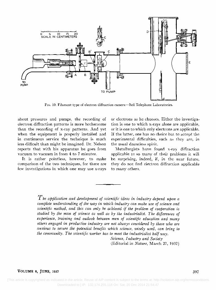
Another embodiment of the same essential features is illustrated in Fig. 10. This is a diagram of a camera developed at the BeIl Telephone Laboratories. The electrons come from a tungsten filament at A, and are accelerated from A to B. The beam is defined by small apertures in parts Band B'. The alignment of the beam is achieved by adjustment of the positions of the apertures through sylphon bellows and by the use of crossed electrostatic fields in the region between Band B'. The specimen, in a mounting adjustable through bellows, is placed just beyond the second aperture. The fluorescent screen closes the end of the main tube. The photographic plate is held until wanted in the upper part of the vertical cylinder shown in the drawing. It can be lowered into position for exposure or withdrawn by gas-tight mechanical couplings to the outside. Adjustable stops are set to limit the amount of plate exposed. With exposures limited to strips one or two centimeters wide, portions of 10 or 15 patterns can be recorded on a single plate. This camera is in daily use on corrosion and other problems arising in the telephone plant.
I hardly need point out that what with having to open and reseal the camera to change specimens and plates, and what with having to worry
JOURNAL OF APPLIED PHYSICS
[This article is copyrighted as indicated in the article. Reuse of AIP content is subject to the terms at: http://scitation.aip.org/termsconditions.
Downloaded to ] IP: 132.174.255.116 On: Sat, 20 Dec 2014 21:54:47
TO PUMP
I " I ! ! ,!
o 5 10 15 20 SCALE IN CENTIMETERS
E
TO PUMP
FIG. 10. Filament type of electron diffraction camera-Bell Telephone Laboratories.
about pressures and pumps, the recording of electron diffraction patterns is more bothersome than the recording of x-ray patterns. And yet when the equipment is properly installed and in continuous service the technique is much less difficult than might be imagined. Dr. Nelson reports that with his apparatus he goes from vacuum to vacuum in from 4 to 7 minutes.
It is rather pointless, however, to make comparison of the two techniques, for there are few investigations in which one may use x-rays
or electrons as he chooses. Either the investigation is one to which x-rays alone are applicable, or it is one to which only electrons are applicable. If the latter, one has no choice but to accept the experimental difficulties, such as they are, in the usual dauntless spirit.
Metallurgists have found x-ray diffraction applicable to so many of their problems it will be surprising, indeed, if, in the near future, they do not find electron diffraction applicable to many others.
T he application and development of scientific ideas in industry depend upon a complete understanding of the way in which industry can make use of science and scientific method, and this can only be achieved if the problem of cooperation is studied by the man of science as well as by the industrialist. The differences of experience, training and outlook between men of scientific education and many others engaged in productive industry are not always considered by those who are anxious to secure the potential benefits which science, wisely used, can bring to the community. The scientific worker has to meet the industrialist half way.
VOLUME 8, JUNE, 1937
Science, Industry and Society (Editorial in Nature, March 27,1937)
397
[This article is copyrighted as indicated in the article. Reuse of AIP content is subject to the terms at: http://scitation.aip.org/termsconditions.
Downloaded to ] IP: 132.174.255.116 On: Sat, 20 Dec 2014 21:54:47