westpro 10k generator om june2014 cc - the home depot · this manual contains important...
TRANSCRIPT


2
DISCLAIMERS:All information, illustrations and specifications in this manual are based on the latest information available at the time of publishing. The illustrations used in this manual are intended as representative reference views only. Moreover, because of our continuous product improvement policy, we may modify information, illustrations and/or specifications to explain and/or exemplify a product, service or maintenance improvement. We reserve the right to make any change at any time without notice. Some images may vary depending upon which model is shown.
ALL RIGHTS RESERVED:No part of this publication may be reproduced or used in any form by any means – graphic, electronic or mechanical, including photocopying, recording, taping or information storage and retrieval systems – without the written permission of Westpro Power Systems, LLC.
CaliforniaProposition 65 Warning
Certain components in this product and itsrelated accessories contain chemicals
known to the state of California to causecancer, birth defects or other reproductive
harm. Wash hands after handling.
CaliforniaProposition 65 Warning
The engine exhaust from this productcontains chemicals known to the state ofCalifornia to cause cancer, birth defects
or other reproductive harm.

CONGRATULATIONS ON OWNING A WESTINGHOUSE GENERATOR
! DANGER
!This manual contains important instructions for operating this generator. For your safety and the safety of others, be sure to read this manual thoroughly before operating the generator. Failure to properly follow all instructions and precautions can cause you and others to be seriously hurt or killed.
For Your Records:Date of Purchase: Generator Model Number:
Purchased from Store/Dealer: Generator Serial Number:
Purchase Receipt: (retain your purchase receipt to ensure trouble-free warranty coverage)
Product RegistrationTo ensure trouble-free warranty coverage, it is important you register your Westinghouse generator. You can register your generator by either:
1. Filling in the product registration form below and mailing to:
Product Registration
Westpro Power Systems, LLC
W237 N2889 Woodgate Road, Unit B
Pewaukee, WI 53072
2. Registering your product online at www.westpropower.com
To register your generator you will need to locate the following information:
Model Number Serial Number
Class F
Product Registration FormPERSONAL INFORMATION GENERATOR INFORMATION
First Name: Model Number:
Last Name: Serial Number:
Street Address: Date Purchased:
Street Address: Purchased From:
City, State, ZIP:
Country:
Phone Number:
E-Mail:


5
TABLE OF CONTENTSCONGRATULATIONS ON OWNING A WESTINGHOUSE GENERATOR .........................................................3
For Your Records: .........................................................................................................................................3Product Registration .....................................................................................................................................3Product Registration Form ............................................................................................................................3
SAFETY ....................................................................................................................................................................7SAFETY DEFINITIONS ......................................................................................................................................7SAFETY SYMBOL DEFINITIONS ......................................................................................................................7GENERAL SAFETY RULES ...............................................................................................................................8SAFETY LABELS AND DECALS – 10KPRO ...................................................................................................10SAFETY LABELS AND DECALS – 8KPRO .....................................................................................................12
UNPACKING ...........................................................................................................................................................14UNPACKING THE GENERATOR ......................................................................................................................14WHEEL KIT ACCESSORIES ............................................................................................................................14
Components: ..............................................................................................................................................14ASSEMBLY .............................................................................................................................................................15
ASSEMBLY .......................................................................................................................................................15INSTALLING THE BATTERY.............................................................................................................................16
FEATURES .............................................................................................................................................................18GENERAL GENERATOR FEATURES – 10KPRO ............................................................................................18CONTROL PANEL FEATURES – 10KPRO ......................................................................................................20GENERAL GENERATOR FEATURES – 8KPRO ..............................................................................................21CONTROL PANEL FEATURES – 8KPRO ........................................................................................................23
OPERATION ...........................................................................................................................................................24BEFORE STARTING THE GENERATOR .........................................................................................................24POWER CORD .................................................................................................................................................25
Using Extension Cords ...............................................................................................................................25Transfer Switch Cord – 10KPRO ................................................................................................................26
TRANSFER SWITCH CONNECTIONS ............................................................................................................26LIFTING BRACKET ..........................................................................................................................................27GENERATOR ANCHOR ...................................................................................................................................27ADDING / CHECKING ENGINE FLUIDS AND FUEL .......................................................................................28
Checking and / or Adding Engine Oil ..........................................................................................................28Adding Gasoline to the Fuel Tank ...............................................................................................................28
PROGRAMMING THE GENERATOR FOR REMOTE START ..........................................................................29STARTING THE GENERATOR .........................................................................................................................29STOPPING THE GENERATOR ........................................................................................................................32
Normal Operation .......................................................................................................................................32During an Emergency .................................................................................................................................32
STARTING THE GENERATOR USING REMOTE START ................................................................................32STOPPING THE GENERATOR USING REMOTE START................................................................................33
MAINTENANCE ......................................................................................................................................................34MAINTENANCE ................................................................................................................................................34 Maintenance Schedule ...............................................................................................................................34ENGINE OIL MAINTENANCE ..........................................................................................................................35
Engine Oil Specification ..............................................................................................................................35Checking Engine Oil – 10KPRO .................................................................................................................35Checking Engine Oil – 8KPRO ...................................................................................................................36Adding Engine Oil – 10KPRO .....................................................................................................................36Adding Engine Oil – 8KPRO .......................................................................................................................37Changing Engine Oil – 10KPRO ................................................................................................................37Changing Engine Oil – 8KPRO ..................................................................................................................38
AIR FILTER MAINTENANCE ............................................................................................................................39Inspect and Replace the Air Filter – 10KPRO ............................................................................................39Cleaning the Air Filter – 8KPRO .................................................................................................................40
SPARK PLUG MAINTENANCE ........................................................................................................................42BATTERY SERVICE .........................................................................................................................................43 Battery Replacement ..................................................................................................................................44

6
TABLE OF CONTENTSCLEANING THE ENGINE OIL COOLER – 10KPRO ........................................................................................45TESTING THE GROUND FAULT SENSOR ......................................................................................................46CLEANING THE GENERATOR ........................................................................................................................46QUICK DRAIN...................................................................................................................................................48STORAGE .........................................................................................................................................................49
TROUBLESHOOTING ............................................................................................................................................50TROUBLESHOOTING ......................................................................................................................................50

7
SAFETY
SAFETY DEFINITIONSThe words DANGER, WARNING, CAUTION and NOTICE are used throughout this manual to highlight important information. Be certain that the meanings of these alerts are known to all who work on or near the equipment.
!This safety alert symbol appears with most safety statements. It means attention, become alert, your safety is involved! Please read and abide by the message that follows the safety alert symbol.
! DANGERIndicates a hazardous situation which, if not avoided, will result in death or serious injury.
! WARNINGIndicates a hazardous situation which, if not avoided, could result in death or serious injury.
! CAUTIONIndicates a hazardous situation which, if not avoided, could result in minor or moderate injury.
NOTICEIndicates a situation which can cause damage to the generator, personal property and/or the environment, or cause the equipment to operate improperly.
OTE:N Indicates a procedure, practice or condition that should be followed in order for the generator to function in the manner intended.
SAFETY SYMBOL DEFINITIONS
Symbol Description
! Safety Alert Symbol
Asphyxiation Hazard
Burn Hazard
Burst/Pressure Hazard
Don’t leave tools in the area
Electrical Shock Hazard
Explosion Hazard
Fire Hazard
Lifting Hazard
Pinch-Point Hazard
Read Manufacturer’s Instructions
Read Safety Messages Before Proceeding
Wear Personal Protective Equipment(PPE)

8
SAFETY
GENERAL SAFETY RULES
! DANGERNever use the generator in a location that is wet or damp. Never expose the generator to rain, snow, water spray or standing water while in use. Protect the generator from all hazardous weather conditions. Moisture or ice can cause a short circuit or other malfunction in the electrical circuit.
Never operate the generator in an enclosed area. Engine exhaust contains carbon monoxide. Only operate the generator outside and away from windows, doors and vents.
! WARNINGVoltage produced by the generator could result in death or serious injury.• Never operate the generator in
rain or a floodplain unless proper precautions are taken to avoid being subject to rain or a flood.
• Never use worn or damaged extension cords.
• Always have a licensed electrician connect the generator to the utility circuit.
• Never touch an operating generator if the generator is wet or if you have wet hands.
• Never operate the generator in highly conductive areas such as around metal decking or steel works.
• Always use grounded extension cords. Always use three-wire or double-insulated power tools.
• Never touch live terminals or bare wires while the generator is operating.
• Be sure the generator is properly grounded before operating.
! WARNINGGasoline and gasoline vapors are extremely flammable and explosive under certain conditions.• Always refuel the generator outdoors,
in a well-ventilated area.• Never remove the fuel cap with the
engine running.• Never refuel the generator while
the engine is running. Always turn engine off and allow the generator to cool before refueling.
• Only fill fuel tank with gasoline. • Keep sparks, open flames or other
form of ignition (such as match, cigarette, static electric source) away when refueling.
• Never overfill the fuel tank. Leave room for fuel to expand. Overfilling the fuel tank can result in a sudden overflow of gasoline and result in spilled gasoline coming in contact with HOT surfaces. Spilled fuel can ignite. If fuel is spilled on the generator, wipe up any spills immediately. Dispose of rag properly. Allow area of spilled fuel to dry before operating the generator.
• Wear eye protection while refueling.• Never use gasoline as a cleaning
agent. • Store any containers containing
gasoline in a well-ventilated area, away from any combustibles or source of ignition.
• Check for fuel leaks after refueling. Never operate the engine if a fuel leak is discovered.

9
SAFETY
! WARNINGNever operate the generator if powered items overheat, electrical output drops, there is sparking, flames or smoke coming from the generator, or if the receptacles are damaged.
!Never use the generator to power medical support equipment.
Always remove any tools or other service equipment used during maintenance from the generator before operating.
! WARNINGAlways use caution when around the generator. The generator is equipped with a remote start feature that could be activated, allowing the generator to start without warning.
Always disconnect the negative (-) battery cable when servicing or performing any maintenance on the generator. This will disable the remote start system, which will prevent accidental starting of the generator.
NOTICENever modify the generator.
Never operate the generator if it vibrates at high levels, if engine speed changes greatly or if the engine misfires often.
Always disconnect tools or appliances from the generator before starting.
10
SAFETY
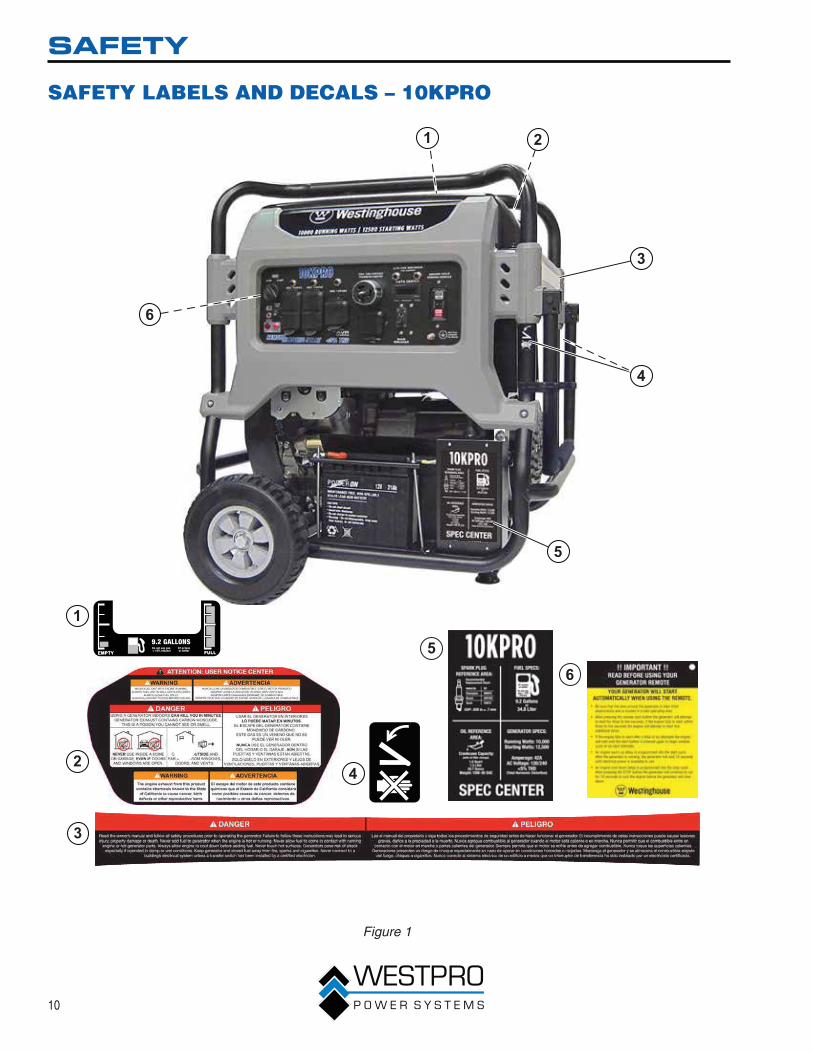
SAFETY LABELS AND DECALS – 10KPRO
1
3
21
6
4
3
56
42
5
Figure 1

11
SAFETY
1
3
4
5
2Class F
2
3
1
4
5
Figure 2

12
SAFETY
SAFETY LABELS AND DECALS – 8KPRO
1
3
21
5
4
3
5
42
Figure 3

13
SAFETY
26
3
1
5
4
1
3
4
5
6
2
Figure 4

14
UNPACKING
UNPACKING THE GENERATOR
! CAUTIONAlways have assistance when lifting the generator. The generator is heavy; lifting it could cause bodily harm.
!Avoid cutting on or near staples to prevent personal injury.
Tools required – box cutter or similar device.
1. Carefully cut the packing tape on top of the carton.
2. Fold back top flaps to reveal the manual.
3. Remove the Wheel Kit Accessories.
4. Carefully cut two sides of the carton to remove the generator.
WHEEL KIT ACCESSORIESIf any parts are missing, please locate an authorized Westinghouse Generator dealer at www.westpropower.com or call 1-855-WHHELP1 (1-855-944-3571).
Components:
Wheels (2)Tool Bag (1)Spark Plug Socket Wrench (1)Battery Charger (1)
0.75 L Bottle of SAE 10W30 Oil – 10KPRO (2)1.0 L Bottle of SAE 10W30 Oil – 8KPRO (1)Mounting Foot (1)Oil Funnel (1)Remote Start Key Fob (1)
1
24
3
5
6
Figure 5 – Wheel Kit Hardware
1 - Flange Bolt M8 x 18 mm (2 used)
2 - Locking Flange Nut M8 (4 used)
3 - Serrated Flange Nut M12 (4 used)
4 - Wheel Axle Bolt M12 x 1.5 mm (2 used)
5 - Hex Bolt M8 x 50 mm (2 used)
6 - Spacer Sleeve (2 used)

15
ASSEMBLY
ASSEMBLY
Before assembling the generator, review Safety on page 7 and the following safety messages.
! CAUTIONNever lift the generator without assistance. The generator is heavy and lifting without assistance could result in personal injury.
!Never use the handles as a lifting point to support the entire weight of the generator. Only use the handles to move the generator by lifting the handles and using the wheels to move the generator.
Use caution when collapsing the handles. Hands and fingers could get caught and pinched.
NOTICEAssembling the generator will require lifting the unit. Make sure all engine oil and fuel are drained from the unit prior to assembling.
Once assembled, the wheel kit is not intended for on-road use. The wheel kit is designed for use on this generator only.
Tools required – tool bag (included).
1. Place generator on a flat surface.
2. Using a block of wood, raise and support the back of the generator.
3. Install the mounting foot to the frame using M8 flange bolts and nuts (see Figure 6).
3
1
2
Figure 6 – Assemble Mounting Foot to Frame
1 - M8 Flange Bolt
2 - M8 Flange Nut
3 - Mounting Foot
4. Install the 12 mm x 1.5 mm axle bolt through the axle bracket on the frame.
5. Install the flange nut and tighten (see Figure 7).
3
2
1
Figure 7 – Assemble Wheels to Frame
1 - Flange Nut
2 - Wheel
3 - Axle Bolt

16
ASSEMBLY6. Install the lifting bracket using the hex bolts,
spacers and locknuts (see Figure 8).
1
2
3 4
Figure 8 – Installing Lifting Bracket
1 - Lifting Bracket
2 - Hex Bolt
3 - Spacer Sleeve
4 - Locknut
INSTALLING THE BATTERY
! WARNINGTo avoid electric shock:• ALWAYS connect the positive (+)
battery cable (red boot) first when connecting battery cables.
• ALWAYS disconnect the negative (-) battery cable (black boot) first when disconnecting battery cables.
• NEVER connect the negative (-) battery cable (black boot) to the positive (+) post on the battery.
• NEVER connect the positive (+) battery cable (red boot) to the negative (-) post on the battery.
• NEVER touch both battery posts simultaneously.
• NEVER place a metal tool across both battery posts.
• ALWAYS use insulated or non-conducting tools when installing the battery.
OTE:N The generator comes equipped with the positive battery cable (red boot) already attached.
1. Verify the positive (+) battery cable (red boot) is securely tightened to the positive (+) battery post. Make sure boot is over battery post.
2. Carefully remove the protective wrapping around the lug of the negative (-) battery cable (black boot).
3. Locate negative (-) cable attached to alternator cable, remove tie and route to the negative (-) battery post.

17
ASSEMBLY4. Pull back the black boot and securely attach
the negative (-) battery cable (black boot) to the negative (-) battery post as shown in Figure 9. Replace the black boot so it protects the cable lug and battery post.
1
2
Figure 9 – Attaching the Negative (-) Battery Cable (Black)
1 - Positive (+) Battery Cable (Red)
2 - Negative (-) Battery Cable (Black)

18
FEATURES
GENERAL GENERATOR FEATURES – 10KPRO
1
4
3
2
Figure 10
1 - Engine Control Switch: Turns the engine on and off.
2 - Control Panel: Contains the circuit breakers and outlets.
3 - Battery: Used for starting the generator.
4 - Oil Dipstick: Remove the dipstick to check the engine oil.

19
FEATURES
7
2
3
4
1
5
6
Figure 11
1 - Fuel Gauge: Indicates fuel level.
2 - Fuel Shutoff Valve: Controls the flow of fuel to the engine.
3 - Air Cleaner Cover: Must remove to service the air cleaner.
4 - Quick Drain Valve: Use to drain contaminants from the fuel tank.
5 - Oil Fill Cap: Remove to add engine oil.
6 - Spark Plug Boot (Wire): Must be removed when servicing the engine or the spark plug.
7 - Muffler: Avoid contact until the engine is cooled down.

20
FEATURES
CONTROL PANEL FEATURES – 10KPRO
3 54 6 7 8
9
1112 101415 13
21
Figure 12 – Control Panel Features
1 - Battery Charger Port: Plug the 120-volt AC charger into this port to charge the generator battery.
2 - Low Idle Control: With the smart idle switch in the ON (I) position, if there is no load present to any of the outlets for 5 seconds or longer, the engine speed will reduce to 1800 RPM. If a load is applied to any of the outlets, the engine speed will automatically increase to 3600 RPM. With the smart idle control in the OFF (O) position, the engine will constantly run at 3600 RPM.
3 - 20-Amp Circuit Breakers: Each circuit breaker limits the current that can be delivered through the 120-volt duplex outlets to 20 amps.
4 - 120-Volt, 30-Amp Twist Lock Outlet: The outlet can supply 120V output up to 30 amps.
5 - 120-Volt, 30-Amp Circuit Breakers: The circuit breaker limits the current that can be delivered through the 120-volt outlet to 30 amps.
6 - 120/240-Volt, 50-Amp Twist Lock Outlet: Outlet can supply either 120V or 240V output.
7 - Data Center: The data center displays voltage, frequency and accumulated run time.
8 - 120/240-Volt, 30-Amp Circuit Breakers: The circuit breakers limit the current that can be delivered through the 120/240-volt outlet to 30 amps.
9 - Ground Fault Sensor: The sensor will scan all the outlets on the control panel for a ground fault. If a ground fault is detected from any of the outlets, the sensor will automatically trip the main circuit breaker.
10 - Ground Terminal: The ground terminal is used to ground the generator.
11 - Main Circuit Breaker: The main circuit breaker controls total output of all outlets to protect the generator.
12 - 120/240-Volt, 30-Amp Twist Lock Outlet (NEMA L14-30): The outlet can supply either 120V or 240V output up to 30 amps.
13 - 120-Volt, 20-Amp Duplex Outlets: Each outlet is capable of carrying a maximum of 20 amps on a single outlet or a combination of all outlets.
14 - Remote Start Program Button: Use this button along with the key fob to program the generator to be started remotely.
15 - Remote Start Indicator Light: The light will light or flash depending on the status of the remote start system.

21
FEATURES
GENERAL GENERATOR FEATURES – 8KPRO
1
3
24
Figure 14
1 - Engine Control Switch: Turns the engine on and off.
2 - Control Panel: Contains the circuit breakers and outlets.
3 - Oil Fill Plug/Dipstick: Must be removed to add and check oil.
4 - Fuel Gauge: Indicates fuel level.

22
FEATURES
2
3
4
1
5
Figure 15
1 - Muffler: Avoid contact until the engine is cooled down.
2 - Spark Plug Boot (Wire): Must be removed when servicing the engine or the spark plug.
3 - Quick Drain Valve: Use to drain contaminants from the fuel tank.
4 - Recoil Handle: Used to start the generator manually.
5 - Air Cleaner Cover: Must remove to service the air cleaner.

23
FEATURES
CONTROL PANEL FEATURES – 8KPRO
3 4 5 6
89 712 11 10
1 2
Figure 16 – Control Panel Features
1 - Battery Charger Port: Plug the 120-volt AC charger into this port to charge the generator battery.
2 - Low Idle Control: With the smart idle switch in the ON (I) position, if there is no load present to any of the outlets for 5 seconds or longer, the engine speed will reduce to 1800 RPM. If a load is applied to any of the outlets, the engine speed will automatically increase to 3600 RPM. With the smart idle control in the OFF (O) position, the engine will constantly run at 3600 RPM.
3 - 20-Amp Circuit Breakers: Each circuit breaker limits the current that can be delivered through the 120-volt duplex outlets to 20 amps.
4 - Data Center: The data center displays voltage, frequency and accumulated run time.
5 - 120/240-Volt, 30-Amp Twist Lock Outlet (NEMA L14-30): The outlet can supply either 120V or 240V output up to 30 amps.
6 - Ground Fault Sensor: The sensor will scan all the outlets on the control panel for a ground fault. If a ground fault is detected from any of the outlets, the sensor will automatically trip the main circuit breaker.
7 - Ground Terminal: The ground terminal is used to ground the generator.
8 - Main Circuit Breaker: The main circuit breaker controls total output of all outlets to protect the generator.
9 - 120-Volt, 30-Amp Twist Lock Outlet: The outlet can supply 120V output up to 30 amps.
10 - 120-Volt, 20-Amp Duplex Outlets: Each outlet is capable of carrying a maximum of 20 amps on a single outlet or a combination of all outlets.
11 - Remote Start Program Button: Use this button along with the key fob to program the generator to be started remotely.
12 - Remote Start Indicator Light: The light will light or flash depending on the status of the remote start system.

24
OPERATION
BEFORE STARTING THE GENERATOR
Before starting the generator, review Safety on page 7.
Location Selection – Before starting the generator, avoid exhaust and location hazards by verifying:
You have selected a location to operate the generator that is outdoors and well ventilated.
You have selected a location with a level and solid surface on which to place the generator.
You have selected a location that is at least 6 feet (1.8 m) away from any building, other equipment or combustible material.
If the generator is located close to a building, make sure it is not located near any windows, doors and/or vents.
! WARNINGAlways operate the generator on a level surface. Placing the generator on non-level surfaces can cause the generator to tip over, causing fuel and oil to spill. Spilled fuel can ignite if it comes in contact with an ignition source such as a very hot surface.
NOTICEOnly operate the generator on a solid, level surface. Operating the generator on a surface with loose material such as sand or grass clippings can cause debris to be ingested by the generator that could:
• Block cooling vents
• Block air intake system
Weather – Never operate your generator outdoors during rain, snow or any combination of weather conditions that could lead to moisture collecting on, in or around the generator.
Dry Surface – Always operate the generator on a dry surface free of any moisture.
No Connected Loads – Make sure the generator has no connected loads before starting it. To ensure there are no connected loads, unplug any electrical extension cords that are plugged into the control panel receptacles.
NOTICEStarting the generator with loads already applied to it could result in damage to any appliance being powered off the generator during the brief start-up period.
Grounding the Generator – The National Electric Code (NEC), as well as many local electrical codes, require the generator to be connected to earth ground before operating. Before starting the generator, make sure it is connected to earth ground by connecting the ground terminal on the control panel (see Figure 17) to earth ground using copper wire (minimum 10 AWG). Consult a qualified electrician for local grounding requirements.
Figure 17 – Ground Terminal on the Control Panel

25
OPERATION
! WARNINGBe sure the generator is properly connected to earth ground before operating. The generator must be grounded to prevent electrical shock due to faulty appliances.
POWER CORD
Using Extension CordsWestpro Power Systems assumes no responsibility for the content within this table. The use of this table is the responsibility of the user only. This table is intended for reference only. The results produced by using this table are not guaranteed to be correct or applicable in all situations as the type and construction of cords are highly variable. Always check with local regulations and a licensed electrician prior to installing or connecting an electrical appliance.
Extension Cord Wire Gauge Size
Amps 10 20 30 40 50 60 80 100 120
5 20 18 16 14 12 12 10 10 8
10 18 16 14 12 12 10 10 8 8
15 16 14 12 12 10 10 8 8 6
20 14 12 12 10 10 8 8 6 6
25 12 12 10 10 8 8 6 6 6
30 12 10 10 8 8 6 6 6 6
35 10 10 8 8 6 6 6 6 6
40 10 8 8 6 6 6 - - -
45 8 8 6 6 6 - - - -
50 8 6 6 6 - - - - -
Length of Extension Cord (ft)

26
OPERATION
Transfer Switch Cord – 10KPROThe transfer switch cord, Part No. 210051, is an optional accessory for the portable generator. It is used to connect the 50-amp twist lock outlet of the generator to the transfer switch. If your transfer switch does not come with a transfer switch cord, order the cord from Westpro Power.
Figure 18 – Transfer Switch Cord
TRANSFER SWITCH CONNECTIONSThe Westinghouse generator is wired with the neutral bonded to ground. If you are connecting your generator to a transfer switch, the electrician must first determine what type transfer switch is being used. Transfer switches for this equipment are either two-pole or three-pole types.
A two-pole transfer switch will not switch the neutral from the generator to the service panel. That means the generator will be grounded to the service panel. To use the generator with two-pole transfer switches, the electrician will need to change the neutral from bonded to floating.
Remove the ground screw from the wires (see Figure 19). Wrap the terminal end of the green wire with electrical tape so it is insulated. Tape the green wire to the yellow/green wire so it cannot contact any moving parts. Connect the yellow/green wire back to ground using the ground screw.
3 21
Figure 19 – Bonding Wire
1 - Ground Screw
2 - Green Wire
3 - Yellow/Green Wire

27
OPERATION
LIFTING BRACKET1. Before lifting the generator, inspect the bracket and
make sure it is securely fastened to the generator. Do not lift the generator unless the lifting bracket is securely fastened.
2. Hook a chain or strap through the eye on the lifting bracket and make sure it is securely fastened.
3. Connect a suitable lifting device to the chain or strap.
4. Lift the generator slightly to ensure it is lifting straight and level. Adjust the bracket if required to allow it to lift correctly.
Figure 20 – Lifting Bracket
GENERATOR ANCHORThe generator should be used on a flat, level surface whenever possible. If the particular job site requires the generator to be used on uneven terrain, the generator should be anchored. Insert a stake or piece of rebar through the anchor bracket on the frame (see Figure 21). Drive the stake into the ground to secure the generator and prevent it from moving.
! WARNING
!Anchoring the generator to the ground does not electrically ground the generator. For proper electrical grounding of the generator, see Grounding the Generator on page 24.
Figure 21 – Anchor Bracket

28
OPERATION
ADDING / CHECKING ENGINE FLUIDS AND FUEL
Before adding/checking engine fluids and fuel, review Safety on page 7.
! DANGERFilling the fuel tank with gasoline while the generator is running can cause gasoline to leak and come in contact with hot surfaces that can ignite the gasoline.
Before starting the generator, always check the level of:
Engine oil
Gasoline in the fuel tank
Once the generator is started and the engine gets warm, it is not safe to add gasoline to the fuel tank or engine oil to the engine while the engine is running or the engine and muffler are hot.
Checking and / or Adding Engine Oil
! WARNINGInternal pressure can build in the engine crankcase while the engine is running. Removing the oil dipstick while the engine is hot can cause extremely hot oil to spray out of the crankcase and can severely burn skin. Allow engine oil to cool for several minutes before removing the oil dipstick.
The unit as shipped does not contain oil in the engine. You must add engine oil before starting the generator for the first time. See Checking Engine Oil – 10KPRO on page 35, Checking Engine Oil – 8KPRO on page 36, Adding Engine Oil – 10KPRO on page 36 and Adding Engine Oil – 8KPRO on page 37 for instructions on checking engine oil level and the procedure for adding engine oil.
NOTICEThe generator does not contain engine oil as shipped. Attempting to start the engine without adding engine oil can permanently damage internal engine components.
Adding Gasoline to the Fuel Tank
! WARNINGNever refuel the generator while the engine is running.
Always turn the engine off and allow the generator to cool before refueling.
Required Gasoline – Only use gasoline that meets the following requirements:
Unleaded gasoline only
Gasoline with maximum 10% ethanol added
Gasoline with an 87 octane rating or higher
Filling the Fuel Tank – Follow the steps below to fill the fuel tank:
1. Shut off the generator.
2. Allow the generator to cool down so all surface areas of the muffler and engine are cool to the touch.
3. Move the generator to a flat surface.
4. Clean area around the fuel cap.
5. Remove the fuel cap by rotating counterclockwise.
6. Slowly add gasoline into the fuel tank. Be very careful not to overfill the tank. The gasoline level should NOT be higher than the bottom of the filler neck (see Figure 22).
7. Install the fuel cap by rotating clockwise until you hear a click, indicating the cap is completely installed.
Figure 22 – Maximum Gasoline Fill Level
! CAUTION
!Avoid prolonged skin contact with gasoline. Avoid prolonged breathing of gasoline vapors.

29
OPERATION
PROGRAMMING THE GENERATOR FOR REMOTE START
! WARNINGAlways make sure the area around the generator is clear of bystanders before using the remote start to start the generator.
The generator can be started remotely from up to a maximum of 109 yards (100 M) away using the remote start key fob with new, fully charged batteries in the key fob. As the batteries’ state of charge in the key fob reduces, the distance to start the generator will also reduce.
Before the generator can be started, an initial start-up procedure must be performed so the generator and the key fob recognize each other. If the key fob is replaced, you will need to go through this procedure with the new fob.
1. Turn the engine control switch to the RUN position.
2. Push and hold the program button on the control panel (see Figure 23) for 3 seconds. The remote start indicator light will light.
1 2
Figure 23 – Remote Start Programming
1 - Remote Start Indicator Light
2 - Remote Start Program Button
3. Press the stop button on the remote start key fob (see Figure 24). The indicator light will flash once and then remain lit.
1
2
Figure 24 – Remote Start Key Fob
1 - Start Button 2 - Stop Button
4. Press the start button on the remote start key fob. The indicator light will flash once and then remain lit.
5. Press and hold the program button for 3 seconds. The indicator light will now turn off after 3 seconds. The generator is now programmed to start remotely.
STARTING THE GENERATOR
Before starting the generator, review Safety on page 7.
Before attempting to start the generator, verify the following:
The engine is filled with engine oil (see Checking Engine Oil – 10KPRO on page 35 and Checking Engine Oil – 8KPRO on page 36).
The generator is situated in a proper location (see Location Selection on page 24).
The generator is on a dry surface (see Weather and Dry Surface on page 24).
All loads are disconnected from the generator (see No Connected Loads on page 24).
The generator is properly grounded (see Grounding the Generator on page 24).
The ground fault sensor is working correctly (see Testing the Ground Fault Sensor on page 46).

30
OPERATION
! DANGERNever use the generator in a location that is wet or damp. Never expose the generator to rain, snow, water spray or standing water while in use. Protect the generator from all hazardous weather conditions. Moisture or ice can cause a short circuit or other malfunction in the electrical circuit.
Never operate the generator in an enclosed area. Engine exhaust contains carbon monoxide. Only operate the generator outside and away from windows, doors and vents.
NOTICEThe engine is equipped with a low oil shutdown switch. If the oil level becomes low, the engine will shut down and will not start until the oil is filled to the proper level.
Be sure the engine has the proper oil level before using. Failure to verify that the engine has the proper oil level could result in engine damage.
Disconnect all loads from the generator before starting. Failure to verify all loads are disconnected prior to starting the generator could result in damage to the connected appliances.
1. Verify the battery is properly installed and both battery cables are attached (see Installing the Battery on page 16).
2. Make sure the circuit breakers are properly set (see Figure 25 and Figure 26).
1 2 3
4
Figure 25 – Circuit Breakers – 10KPRO
1 - 120V Circuit Breaker
2 - 120V 30-Amp Circuit Breaker
3 - 120/240V 30-Amp Circuit Breaker
4 - Main Breaker
1
2
Figure 26 – Circuit Breakers – 8KPRO
1 - 120V Circuit Breaker
2 - Main Breaker

31
OPERATION3. Move the fuel shutoff valve to the ON position (see
Figure 27).
Figure 27 – Fuel Shutoff Valve in the ON Position
NOTICEThis generator is equipped with an automatic choke for starting. This system is always on and cannot be turned off. Do not attempt to make adjustments to the automatic choke or any other carburetor adjustments. Tampering with the automatic choke system may void your warranty. See an authorized Westinghouse service center for more information.
4. Turn the engine control switch to the START position until the engine starts. Once the engine starts, release the engine control switch; the switch will automatically move into the ON position (see Figure 29).
Figure 29 – Engine Control Switch
NOTICEFailure to release the engine control switch once the engine starts could result in damage to the generator.
Never turn the engine control switch to the START position while the engine is running; this could damage the generator.
OTE:N If the engine fails to start after 5 seconds, release the engine control switch. Let the generator sit idle for 15 seconds and then repeat step 4. If the cranking speed drops after each unsuccessful attempt, then the battery may not be adequately charged.
OTE:N The generator is equipped with a battery charging feature. Once the engine is running, a small charge is supplied to the battery via the battery cables and will slowly recharge the battery.

32
OPERATION
STOPPING THE GENERATOR
Normal OperationDuring normal operation, use the following steps to stop your generator:
1. Remove any connected loads from the control panel receptacles.
2. Allow the generator to run at “no load” to reduce and stabilize engine and alternator temperatures.
3. Turn the engine control switch to the OFF position.
4. Turn the fuel shutoff valve to the OFF position.
During an EmergencyIf there is an emergency and the generator must be stopped quickly, push the engine control switch to the OFF position immediately.
STARTING THE GENERATOR USING REMOTE START
Before starting the generator, review Safety on page 7.
Before attempting to start the generator, verify the following:
The engine is filled with engine oil (see Checking Engine Oil – 10KPRO on page 35 and Checking Engine Oil – 8KPRO on page 36).
The generator is situated in a proper location (see Location Selection on page 24).
The generator is on a dry surface (see Weather and Dry Surface on page 24).
All loads are disconnected from the generator (see No Connected Loads on page 24).
The generator is properly grounded (see Grounding the Generator on page 24).
The ground fault sensor is working correctly (see Testing the Ground Fault Sensor on page 46).
! DANGERNever use the generator in a location that is wet or damp. Never expose the generator to rain, snow, water spray or standing water while in use. Protect the generator from all hazardous weather conditions. Moisture or ice can cause a short circuit or other malfunction in the electrical circuit.
! DANGERNever operate the generator in an enclosed area. Engine exhaust contains carbon monoxide. Only operate the generator outside and away from windows, doors and vents.
NOTICEThe engine is equipped with a low oil shutdown switch. If the oil level becomes low, the engine will shut down and will not start until the oil is filled to the proper level.
Be sure the engine has the proper oil level before using. Failure to verify that the engine has the proper oil level could result in engine damage.
Disconnect all loads from the generator before starting. Failure to verify all loads are disconnected prior to starting the generator could result in damage to the connected appliances.
1. Verify the battery is properly installed and both battery cables are attached (see Installing the Battery on page 16).
2. Make sure the circuit breakers are properly set (see Figure 30 and Figure 31).
1 2 3
4
Figure 30 – Circuit Breakers – 10KPRO
1 - 120V Circuit Breaker
2 - 120V 30-Amp Circuit Breaker
3 - 240/120V 30-Amp Circuit Breaker
4 - Main Breaker

33
OPERATION
1
2
Figure 31 – Circuit Breakers – 8KPRO
1 - 120V Circuit Breaker
2 - Main Breaker
3. Move the fuel shutoff valve to the ON position (see Figure 32).
Figure 32 – Fuel Shutoff Valve in the ON Position
NOTICEThis generator is equipped with an automatic choke for starting. This system is always on and cannot be turned off. Do not attempt to make adjustments to the automatic choke or any other carburetor adjustments. Tampering with the automatic choke system may void your warranty. See an authorized Westinghouse service center for more information.
4. Press the start button on the remote start key fob.
5. The generator will turn over for 3 to 5 seconds and start.
6. An engine warmup delay is programmed into the remote start cycle. After the generator is running, there will be a delay of electrical output for 15 seconds.
7. If the engine fails to start within 3 to 5 seconds, the engine will attempt to start five additional times. If the generator failed to start, the remote start indicator light will flash.
8. If the generator fails to start after a total of six attempts, the start button on the key fob must be pushed again to begin another cycle of six start attempts.
STOPPING THE GENERATOR USING REMOTE START1. Make sure there is no load to any of the generator
outlets.
2. Press the stop button on the remote start key fob.
3. The generator will run for an additional 15 seconds as it goes through a cooldown cycle before shutting off.

34
MAINTENANCE
MAINTENANCEBefore performing maintenance on the generator, review Safety on page 7 and the following safety messages.
! WARNING
!Avoid accidentally starting the generator during maintenance by removing the spark plug boot from the spark plug. Also disconnect the battery cables from the battery (disconnect the black negative (-) cable first) and place the cables away from the battery posts to avoid arcing.
Allow hot components to cool to the touch prior to performing any maintenance procedure.
Internal pressure can build in the engine crankcase while the engine is running. Removing the oil dipstick while the engine is hot can cause extremely hot oil to spray out of the crankcase and can severely burn skin. Allow engine oil to cool for several minutes before removing the oil dipstick.
Always perform maintenance in a well-ventilated area. Gasoline fuel and fuel vapors are extremely flammable and can ignite under certain conditions.
Table 1: Maintenance Schedule - Owner Performed
Maintenance Item
Before Every Use
After First 20 Hours or First Month of Use
After 50 Hours of Use or Every
3 Months
After 100 Hours of Use or Every
6 Months
After 300 Hours of Use or Every
Year
Engine Oil Check Level Change Change – –
Cooling Features Check/Clean – – – –
Air Filter Check –Inspect or Replace1 – Replace
Spark Plug – – – Check/Clean Replace1 Service more frequently if operating in dry and dusty conditions.
! CAUTIONAvoid skin contact with engine oil or gasoline. Prolonged skin contact with engine oil or gasoline can be harmful. Frequent and prolonged contact with engine oil may cause skin cancer. Take protective measures and wear protective clothing and equipment. Wash all exposed skin with soap and water.
Maintenance Schedule
! WARNING
!Failure to perform periodic maintenance or not following maintenance procedures can cause the generator to malfunction and could result in death or serious injury.
NOTICEPeriodic maintenance intervals vary depending on generator operating conditions. Operating the generator under severe conditions, such as sustained high-load, high-temperature, or unusually wet or dusty environments, will require more frequent periodic maintenance. The intervals listed in the maintenance schedule should be treated only as a general guideline.
Following the maintenance schedule is important to keep the generator in good operating condition. The following is a summary of maintenance items by periodic maintenance intervals.

35
MAINTENANCE
Table 2: Maintenance Schedule - Authorized Westinghouse Service Dealer Performed
Maintenance Item
Before Every Use
After First 20 Hours or First Month of Use
After 50 Hours of Use or Every
3 Months
After 100 Hours of Use or Every
6 Months
After 300 Hours of Use or Every
Year
Valve Clearance – – – – Check/Adjust
Fuel Filter – – – Check/Clean –
Idle Speed – – – – Check/Adjust
ENGINE OIL MAINTENANCE
Engine Oil Specification1. Only use the engine oil specified in Figure 33.
2. Only use 4-stroke/cycle engine oil. NEVER USE 2-STROKE/CYCLE OIL. Synthetic oil is an acceptable substitute for conventional oil.
5W-30
Convent ional 10W-30
SAE 30
Figure 33 – Recommended Oil
Checking Engine Oil – 10KPRO
NOTICEAlways maintain proper engine oil level. Failure to maintain proper engine oil level could result in severe damage to the engine and/or shorten the life of the engine.
Always use the specified engine oil. Failure to use the specified engine oil can cause accelerated wear and/or shorten the life of the engine.
Engine oil level should be checked before every use.
1. Always operate or maintain the generator on a flat surface.
2. Stop engine if running.
3. Let engine sit and cool for several minutes (allow crankcase pressure to equalize).
4. With a damp rag, clean around the oil dipstick.
5. Remove oil dipstick (see Figure 34).
Figure 34 – Oil Dipstick
6. Check oil level:
When checking the engine oil, remove the oil dipstick and wipe it clean. Insert the dipstick all the way back in and then remove and check the oil level on the dipstick.
Acceptable Oil Level – Oil is visible between the H and L lines on the oil dipstick (see Figure 35).
Low Oil – Oil is below the L line on the oil dipstick.
1 2
Figure 35 – Checking Oil Level
1 - Low Oil Level Line
2 - High Oil Level Line

36
MAINTENANCE
Checking Engine Oil – 8KPRO
NOTICEAlways maintain proper engine oil level. Failure to maintain proper engine oil level could result in severe damage to the engine and/or shorten the life of the engine.
Always use the specified engine oil. Failure to use the specified engine oil can cause accelerated wear and/or shorten the life of the engine.
Engine oil level should be checked before every use.
1. Always operate or maintain the generator on a flat surface.
2. Stop engine if running.
3. Let engine sit and cool for several minutes (allow crankcase pressure to equalize).
4. With a damp rag, clean around the oil fill plug/dipstick.
5. Remove oil fill plug/dipstick (see Figure 36).
Figure 36 – Oil Fill Plug/Dipstick
6. Check oil level:
When checking the engine oil, remove the oil fill plug/dipstick and wipe it clean. Thread the oil fill plug/dipstick all the way back in and then remove and check the oil level on the oil fill plug/dipstick.
Acceptable Oil Level – Oil is visible on the cross-hatches between the H and L lines on the oil fill plug/dipstick (see Figure 37).
Low Oil – Oil is below the L line on the oil fill plug/dipstick.
H
L
Figure 37 – Checking Oil Level
Adding Engine Oil – 10KPRO1. Always operate or maintain the generator on a flat
surface.
2. Stop engine if running.
3. Let engine sit and cool for several minutes (allow crankcase pressure to equalize).
4. Thoroughly clean around the oil fill plug.

37
MAINTENANCE5. Remove oil fill plug (see Figure 38).
Figure 38 – Oil Fill Plug
6. Select the proper engine oil as specified in Figure 33.
7. Using the supplied funnel and tube, slowly add engine oil to the engine. Stop frequently to check the level to avoid overfilling (see Figure 39).
Figure 39 – Adding Engine Oil
8. Continue to add oil until the oil is at the correct level. See Checking Engine Oil – 10KPRO on page 35.
Adding Engine Oil – 8KPRO1. Always operate or maintain the generator on a flat
surface.
2. Stop engine if running.
3. Let engine sit and cool for several minutes (allow crankcase pressure to equalize).
4. Thoroughly clean around the oil fill plug/dipstick.
5. Remove oil fill plug/dipstick and wipe clean.
6. Select the proper engine oil as specified in Figure 33.
7. Using the supplied funnel and tube, slowly add engine oil to the engine. Stop frequently to check the level to avoid overfilling (see Figure 40).
Figure 40 – Adding Engine Oil
8. Continue to add oil until the oil is at the correct level. See Checking Engine Oil – 8KPRO on page 36.
Changing Engine Oil – 10KPRO1. Stop the engine.
2. Let engine sit and cool for several minutes (allow crankcase pressure to equalize).
3. Place oil pan (or suitable container) under the oil drain plug and oil filter.
4. With a damp rag, thoroughly clean around the oil drain plug and oil filter.
5. Turn the oil filter counterclockwise and remove the filter (see Figure 41).

38
MAINTENANCE6. Remove the oil drain plug (see Figure 41). Once
removed, place the oil drain plug on a clean surface.
1
2
Figure 41 – Oil Drain Plug and Filter
1 - Oil Filter (Part No. 180389)
2 - Oil Drain Plug
7. Allow oil to completely drain.
8. Replace oil drain plug.
9. Apply a light film of clean engine oil to the rubber gasket on the oil filter.
10. Install the oil filter by hand-turning clockwise until the rubber gasket contacts the mounting surface. Turn the filter an additional half turn. Do not overtighten.
11. Fill crankcase with oil following the steps outlined in Adding Engine Oil – 10KPRO on page 36.
NOTICENever dispose of used engine oil by dumping the oil into a sewer, on the ground, or into groundwater or waterways. Always be environmentally responsible. Follow the guidelines of the EPA or other governmental agencies for proper disposal of hazardous materials. Consult local authorities or reclamation facility.
12. Dispose of used engine oil properly.
Changing Engine Oil – 8KPRO1. Stop the engine.
2. Let engine sit and cool for several minutes (allow crankcase pressure to equalize).
3. Place oil pan (or suitable container) under the oil drain plug.
4. With a damp rag, thoroughly clean around the oil drain plug.
5. Remove the oil drain plug (see Figure 42). Once removed, place the oil drain plug on a clean surface.
Figure 42 – Oil Drain Plug
6. Remove the oil fill plug so the oil can drain more easily from the oil drain port.
7. Allow oil to completely drain.
8. Replace oil drain plug.
9. Fill crankcase with oil following the steps outlined in Adding Engine Oil – 8KPRO on page 37.
NOTICENever dispose of used engine oil by dumping the oil into a sewer, on the ground, or into groundwater or waterways. Always be environmentally responsible. Follow the guidelines of the EPA or other governmental agencies for proper disposal of hazardous materials. Consult local authorities or reclamation facility.
10. Dispose of used engine oil properly.

39
MAINTENANCE
AIR FILTER MAINTENANCE
! WARNINGNever use gasoline or other flammable solvents to clean the air filter. Use only household detergent soap to clean the air filter.
Inspect and Replace the Air Filter – 10KPROThe air filter must be inspected after every 50 hours of use or 3 months (frequency should be increased if generator is operated in a dusty environment).
1. Turn off the generator and let it cool for several minutes if running.
2. Move the generator to a flat, level surface.
3. Remove the 4 mounting screws from the top of the fuel tank (see Figure 43).
Figure 43 – Fuel Tank Screws
OTE:N The fuel tank is removed for photo purposes. The air cleaner can be serviced without removing the fuel tank.
4. Lift up the fuel tank slightly and unscrew the air cleaner cover knob and remove the cover (see Figure 44).
Figure 44 – Air Cleaner Knob and Cover
5. Remove the air cleaner element (see Figure 45).
Figure 45 – Air Cleaner Element (Part No. 160059)
6. Insert the air cleaner element for dirt, dust and debris. Do not wash the element. If the air cleaner element is dirty, replace the filter.
7. Install the air cleaner element and install the cover and knob (see Figure 46).
Figure 46 – Air Cleaner Cover Installation
8. Install the 4 screws for the fuel tank.

40
MAINTENANCE
Cleaning the Air Filter – 8KPROThe air filter must be cleaned after every 50 hours of use or 3 months (frequency should be increased if generator is operated in a dusty environment).
1. Turn off the generator and let it cool for several minutes if running.
2. Move the generator to a flat, level surface.
3. Unclip the clips on the top and bottom of the air filter cover (see Figure 47) and remove the air filter cover.
Figure 47 – Removing Air Filter Cover
4. Remove the black coarse outside air filter (see Figure 48).
Figure 48 – Removing Coarse Outside Air Filter
5. Remove the gray fine inside air filter (see Figure 49).
Figure 49 – Removing Fine Inside Air Filter

41
MAINTENANCE6. Wash the foam air filter elements by submerging
the elements in a solution of household detergent soap and warm water. Slowly squeeze the foam to thoroughly clean.
NOTICENEVER twist or tear the foam air filter element during cleaning or drying. Only apply slow but firm squeezing action.
7. Rinse in clean water by submerging the air filter elements in fresh water and applying a slow squeezing action.
NOTICENever dispose of soap cleaning solution used to clean the air filter by dumping the solution into a sewer, on the ground, or into groundwater or waterways. Always be environmentally responsible. Follow the guidelines of the EPA or other governmental agencies for proper disposal of hazardous materials. Consult local authorities or reclamation facility.
8. Dispose of used soap cleaning solution properly.
9. Dry the air filter elements by again applying a slow firm squeezing action.
10. Once the air filters are dry, coat the air filters with clean engine oil (see Figure 50).
Figure 50
11. Squeeze the filters to remove any excess oil (see Figure 51).
Figure 51
12. Install the gray fine inside air filter into the air filter housing first.
13. Install the black coarse outside air filter on top of the fine filter.
14. Install the air filter cover by clipping the clips on the top and bottom of the air filter assembly (see Figure 52).
Figure 52 – Installation of Air Filter Cover

42
MAINTENANCE
SPARK PLUG MAINTENANCEThe spark plug must be checked and cleaned after every 100 hours of use or 6 months and must be replaced after 300 hours of use or every year.
1. Stop the generator and let it cool for several minutes if running.
2. Move the generator to a flat, level surface.
3. Remove the spark plug boot by firmly pulling the plastic spark plug boot handle directly away from the engine (see Figure 53 and Figure 54).
NOTICENever apply any side load or move the spark plug laterally when removing the spark plug. Applying a side load or moving the spark plug laterally may crack and damage the spark plug boot.
Figure 53 – Removal of Spark Plug Boot – 10KPRO
Figure 54 – Removal of Spark Plug Boot – 8KPRO
4. Clean area around the spark plug.
5. Using the 13/16" spark plug socket wrench provided, remove the spark plug from the cylinder head (see Figure 55 and Figure 56).
Figure 55 – Removing Spark Plug – 10KPRO

43
MAINTENANCE
Figure 56 – Removing Spark Plug – 8KPRO
6. Place a clean rag over the opening created by the removal of the spark plug to make sure no dirt can get into the combustion chamber.
7. Inspect the spark plug for:
Cracked or chipped insulator
Excessive wear
Spark plug gap (the acceptable limit of 0.024 – 0.032 in. [0.60 – 0.80 mm]) (see Figure 57).
If the spark plug fails any one of the conditions listed above, replace the plug with a Champion RN9YC plug or equivalent.
NOTICEOnly use the recommended spark plug (Champion RN9YC or equivalent). Using a non-recommended spark plug could result in damage to the engine.
Figure 57 – Spark Plug Gap Requirements
8. Install the spark plug by carefully following the steps outlined below:
a - Carefully insert the spark plug back into the cylinder head. Hand-thread the spark plug until it bottoms out.
b - Using the 13/16" spark plug socket wrench provided, turn the spark plug to ensure it is fully seated.
c - Replace the spark plug boot, making sure the boot fully engages the spark plug’s tip.
Recommended Spark Plug Replacement:
AutoLite 63
Champion RN9YC
Bosch WR7DS
Torch F6RTC
BATTERY SERVICETo ensure the battery remains charged, the generator should be started every 2 to 3 months and run for a minimum of 15 minutes or the charger should be plugged into the generator and the generator should be charged overnight. Plug the cord from the charger into the charging port on the generator. Plug the charger into a 110/120-volt AC outlet (see Figure 58).
Figure 58 – 120-Volt AC Charger

44
MAINTENANCE
Battery Replacement1. Remove the spark plug wire from spark plug.
2. Loosen and remove the nuts on the battery hold-down plate and remove the plate from the support rods (see Figure 59).
12
3
Figure 59
1 - Nuts
2 - Battery Hold- Down Plate
3 - Support Rods
3. Tip the battery forward slightly to access battery cables.
4. Disconnect the black negative (-) battery cable from the battery first.
5. Disconnect the red positive (+) battery cable second and remove the battery.
1
2
Figure 60
1 - Red Positive (+) Battery Cable
2 - Black Negative (-) Battery Cable
NOTICEDispose of the used battery properly according to the guidelines established by your local or state government.
6. Install the new battery into the generator frame.
7. Connect the red positive (+) battery cable to the battery first.
8. Connect the black negative (-) battery cable to the battery second.
9. Install the battery hold-down plate using the nuts removed in step 2.
10. Install the spark plug wire onto spark plug.
The battery for 10KPRO is the same as a wheelchair battery.
Type Sealed lead-acid
Model LA-12V20-NB
Volts 12
Amp 21
Dimensions (L x H x W) 7.13 x 3 x 6.63 in. (18.1 x 7.6 x 16.8 cm)

45
MAINTENANCEThe battery for 8KPRO is the same as a motorcycle/utility battery.
Type 14L-A2
Model CYLA214SXTA
Volts 12
Amp 14
Dimensions (L x H x W) 5.9 x 4.33 x 3.43 in. (15.0 x 11.0 x 8.7 cm)
CLEANING THE ENGINE OIL COOLER – 10KPRO1. Remove the screws for the oil cooler (see Figure
61).
21
1
3
Figure 61 – Engine Oil Cooler
1 - Oil Cooler Screws
2 - Oil Cooler Guard
3 - Oil Cooler
2. Remove the oil cooler guard and the oil cooler.
3. Inspect the oil fins for dirt and debris. Clean the fins using compressed air not to exceed 30 psi (207 kPa) (see Figure 62).
Figure 62 – Oil Cooler Fins
4. Install the oil cooler and guard using the screws.
46
MAINTENANCE
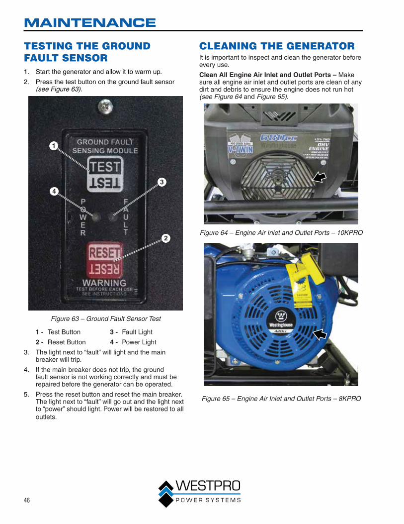
TESTING THE GROUND FAULT SENSOR1. Start the generator and allow it to warm up.
2. Press the test button on the ground fault sensor (see Figure 63).
1
2
34
Figure 63 – Ground Fault Sensor Test
1 - Test Button
2 - Reset Button
3 - Fault Light
4 - Power Light
3. The light next to “fault” will light and the main breaker will trip.
4. If the main breaker does not trip, the ground fault sensor is not working correctly and must be repaired before the generator can be operated.
5. Press the reset button and reset the main breaker. The light next to “fault” will go out and the light next to “power” should light. Power will be restored to all outlets.
CLEANING THE GENERATORIt is important to inspect and clean the generator before every use.
Clean All Engine Air Inlet and Outlet Ports – Make sure all engine air inlet and outlet ports are clean of any dirt and debris to ensure the engine does not run hot (see Figure 64 and Figure 65).
Figure 64 – Engine Air Inlet and Outlet Ports – 10KPRO
Figure 65 – Engine Air Inlet and Outlet Ports – 8KPRO

47
MAINTENANCE
Figure 66 – Engine Cooling Fins – 8KPRO
Clean All Alternator Cooling Air Inlets and Exhaust Ports – Make sure the cooling air inlets and exhaust ports of the alternator are free of any debris and obstructions. Use a vacuum cleaner to remove dirt and debris stuck in the cooling air inlets and exhaust ports (see Figure 67, Figure 68 and Figure 69).
Figure 67 – Alternator Cooling Air Inlet and Outlet Port
Figure 68 – Alternator Cooling Air Inlet and Outlet Port – 10KPRO
Figure 69 – Alternator Cooling Air Inlet and Outlet Port – 8KPRO
General Cleaning of the Generator – Use a damp rag to clean all remaining surfaces.

48
MAINTENANCE
QUICK DRAIN
! WARNINGGasoline and gasoline vapors are extremely flammable and explosive under certain conditions. Wipe up any spills immediately.
The generator is equipped with a quick-drain feature. This feature will prevent the harmful effects of phase-separated ethanol fuels. During the winter, the alcohol and water can separate from the gasoline in blended fuels. Because the water and alcohol are heavier than gasoline, these corrosive fluids will sink to the bottom of the fuel tank.
NOTICENever dispose of hazardous materials irresponsibly by dumping them into a sewer, on the ground, into groundwater or into waterways.
1. Remove the drain hose cap from the end of the drain hose.
2. Open the quick drain valve (see Figure 70) and drain the fuel into a suitable container.
1
2
3
Figure 70 – Quick Drain Valve
1 - Quick Drain Valve
2 - Drain Hose
3 - Drain Hose Cap
3. Water and alcohol will appear clear or cloudy in the fuel. Continue to drain until clean fuel is observed coming out of the end of the drain hose.
4. Close the quick drain valve and install the drain hose cap.
5. Dispose of the collected fuel properly.
6. The quick drain procedure can also be used to transfer fuel from the generator to be used in other gasoline engine products.

49
MAINTENANCE
STORAGE
! WARNINGNever store a generator with fuel in the tank indoors or in a poorly ventilated area where the fumes can come in contact with an ignition source such as a: 1) pilot light of a stove, water heater, clothes dryer or any other gas appliance; or 2) spark from an electric appliance.
NOTICEGasoline stored for as little as 60 days can go bad, causing gum, varnish and corrosive buildup in fuel lines, fuel passages and the engine. This corrosive buildup restricts the flow of fuel, preventing an engine from starting after a prolonged storage period.
Proper care should be taken to prepare the generator for any storage.
1. Clean the generator as outlined in Cleaning the Generator on page 46.
2. Drain all gasoline from the fuel tank as best as possible.
3. With the fuel shutoff valve open, start the engine and allow the generator to run until all the remaining gasoline in the fuel lines and carburetor is consumed and the engine shuts off.
4. Close the fuel shutoff valve.
5. Change the oil (see Changing Engine Oil – 10KPRO on page 37 and Changing Engine Oil – 8KPRO on page 38).
6. Remove the spark plug (see Spark Plug Maintenance on page 42) and place about 1 tablespoon of oil in the spark plug opening. While placing a clean rag over the spark plug opening, slowly pull the recoil handle to allow the engine to turn over several times. This will distribute the oil and protect the cylinder wall from corroding during storage.
7. Replace the spark plug (see Spark Plug Maintenance on page 42).
8. Move the generator to a clean, dry place for storage.

50
TROUBLESHOOTING
TROUBLESHOOTING
! WARNINGBefore attempting to service or troubleshoot the generator, the owner or service technician must first read the owner’s manual and understand and follow all safety instructions. Failure to follow all instructions may result in conditions that can lead to voiding of the EPA certification or product warranty, serious personal injury, property damage or even death.
PROBLEM POTENTIAL CAUSE SOLUTION
Engine is running, but no electrical output.
1. Circuit breakers are tripped. 1. Reset the circuit breakers and check for overload condition (see page 30).
2. The ground fault sensor is tripped.
2. Reset the ground fault sensor (see page 46).
3. The power cord’s plug connector is not fully engaged in the generator’s outlet.
3. Verify plug connector is firmly engaged in the generator’s outlet. If using the 240V outlet, make sure plug connector is rotated 1/4 turn in the clockwise direction.
4. Faulty or defective power cord 4. Replace power cord.
5. Faulty or defective electrical appliance
5. Try connecting a known good appliance to verify the generator is producing electrical power.
6. If trying 1-5 above does not solve the problem, the cause might be the generator has a fault.
6. Take the generator to your nearest authorized service dealer.
Engine will not start or remain running while trying to start.
1. Fuel shutoff valve is in the OFF position.
1. Move the fuel shutoff valve to the ON position (see page 31).
2. Generator is out of gasoline. 2. Add gasoline to the generator (see page 28).
3. Fuel flow is obstructed. 3. Inspect and clean fuel delivery passages.
4. Starting battery may have insufficient charge
4. Check battery output and charge battery as necessary.
5. Dirty air filter 5. Inspect and replace the air filter (see page 39).
6. Low oil level shutdown switch is preventing the unit from starting.
6. Check oil level and add oil if necessary (see pages 35 and 36).
7. Spark plug boot is not fully engaged with the spark plug tip.
7. Firmly push down on the spark plug boot to ensure the boot is fully engaged (see page 42).
8. Spark plug is faulty. 8. Remove and check the spark plug. Replace if faulty (see page 42).
9. Stale fuel 9. Drain fuel and replace with fresh fuel (see page 27).
10. If trying 1-9 above does not solve the problem, the cause might be the generator has a fault.
10. Take the generator to your nearest authorized service dealer.

51
TROUBLESHOOTING
PROBLEM POTENTIAL CAUSE SOLUTION
Remote start system not working.
1. Low battery in remote start key fob
1. Replace batteries in key fob.
2. Exceeding the range of remote start key fob
2. Move closer to generator. Must be no more than 109 yards (100 M) away.
3. Remote start key fob not programmed to generator
3. Program key fob to generator (see Programming the Generator for Remote Start on page 29).
Generator suddenly stops running.
1. Generator is out of fuel. 1. Check fuel level (see page 27). Add fuel if necessary.
2. The low oil shutdown switch has stopped the engine.
2. Check oil level and add oil if necessary (see pages 35 and 36).
3. Too much load 3. Restart the generator and reduce the load.
4. If trying 1-3 above does not solve the problem, the cause might be a fault in the generator.
4. Take the generator to your nearest authorized service dealer.
Engine runs erratic; does not hold a steady RPM.
1. Dirty air filter 1. Replace the air filter (see page 39).
2. Applied loads may be cycling on and off
2. As applied loads cycle, changes in engine speed may occur; this is a normal condition.
3. If trying 1-2 above does not solve the problem, the cause might be a fault in the generator
3. Take the generator to your nearest authorized service dealer.


