western junction quarry extension development proposal …
TRANSCRIPT
J O H N M I E D E C K E & P A R T N E R S P L • March 2 0 1 9
D . N . H u g h es
Western junction quarryextension
DEVELOPMENT PROPOSAL ANDENVIRONMENTAL MANAGEMENT
PLAN

D.N.Hughes
Western Junction Quarry Extension
Development Proposal and Environmental Management Plan
March 2019
John Miedecke and Partners Pty Ltd 41 Tasma St North Hobart Tasmania 7000 03 62311472 Fax 0362311548 [email protected]
Version 3

FOREWORD
This Development Proposal and Environmental Management Plan (DPEMP) describes the proposed operation of a quarry extension owned by Mr Hughes and operated by Bis Industries and environmental management practices for the quarry and its proposed change in operation. The quarry has been in operation since 1982.
It contributes significantly to the basis by which the Board of the Environmental Protection Authority (EPA) (‘the Board’) can conduct an environmental impact assessment under the Environmental Management and Pollution Control Act (EMPCA) (1994), and assess the applications for a Permit by Mr Hughes.
Preparation of the DPEMP has been undertaken in accordance with guidelines prepared by the Environment Protection Authority (EPA). A Land Use Permit will be required from Northern Midlands Council for the quarry and this DPEMP provides supporting information for the application.
The DPEMP also fulfils the role of providing information on the proposed activities to other decision-making authorities and the public, who have the opportunity to make submissions on the proposal under Section 57 of the Land Use Planning and Approvals Act (LUPAA) (1993). Submissions may be lodged, as specified, under Section 57 of the LUPAA (1993) within 28 days of advertisements being placed in local newspapers.
In accordance with Section 25 of the EMPCA (1994), the Council will refer the application to the Board for assessment under that Act and will provide to the Board copies of representations they receive pursuant to the advertisements. The Board will undertake its assessment in accordance with Section 74 of the EMPCA (1994), and will notify Northern Midlands Council of any condition or restriction, which must be included in any permit granted by Council, or direct Council to refuse to grant the permit.
Once the Board has issued direction to the Planning Authority, i.e. Council, and decisions concerning the issue of Land Use Permits have been made, advertised in local newspapers and notices given as required, under the LUPAA (1993), parties who had previously lodged a submission have 14 days in which to lodge an appeal against the decision.

D.N.Hughes Western Junction Quarry Extension DPEMP – SUMMARY
john miedecke and partners pty ltd March 2019
1
SUMMARY Introduction Bis Quarries Pty Ltd operate the Western Junction Quarry on private land owned by Mr Hughes at Breadalbane in Northern Tasmania. The quarry has been in operation for over thirty years and provides a wide selection of construction and building materials essential for regional development without any significant adverse environmental effects. It is also well located to provide construction materials being situated in close proximity to a major road network close to Launceston and in an isolated area of private land well screened from residences and local views. It is an important supplier to the civil construction industry in Northern Tasmania.
Due to declining reserves of basalt rock in the existing quarry Mr Hughes is applying for a level 2 permit at a production level of 312,500 cubic metres of product per annum for a quarry extension located in close proximity. Concurrently, Mr Hughes has applied for a Mining Lease ((MLA 2045P/M) over the future production area to allow for planned operations of over 20 years.
Environment The Western Junction Quarry Extension (ML 2045 P/M) is located on private property off Evandale Road, approximately 2 km south–east of Breadalbane and the Midland Highway. The existing quarry and extension are located immediately north-east of the Launceston Airport and due south of quarries at Mt Oriel and Raeburn (Figure 1). The Josef Chromy Vineyard is immediately to the north -east. Adjoining the airport are industrial and light industrial land uses. The nearest residence to the north-west, is approximately 1 km away.
FIGURE 1: LOCATION – Western Junction Tasmania
The existing quarry has been developed in a north- easterly direction and as a “pit” (ie
D.N.Hughes Western Junction Quarry Extension DPEMP – SUMMARY
john miedecke and partners pty ltd March 2019
2
sunken into the ground surface). As a result, it has only limited visibility to the east and is not visible from other directions. Photograph 1 shows the extension area, which is comprised of grazing land.
Photograph 1 – Proposed quarry extension area
Quarrying Description The proposed quarry extension will extend the quarry in a south - westerly direction from the current (Main) Pit floor (Figure 2).
Quarrying will be in approximately 12 metre deep benches, and developed in stages with topsoils/subsoils stripped and stockpiled ahead of the rock blasting and removal. Figure 3 shows an approximate 3D perspective of the quarry pit at year 10. Rainfall falling on disturbed areas will be directed to a series of retention ponds prior to discharge to the water supply pond in Briarly Creek.
The quarry activities will be similar to what has happened to date and will involve site preparation, rock drilling and blasting, cartage, crushing and screening at the existing plant. Operating hours will be the same.

D.N.Hughes Western Junction Quarry Extension DPEMP – SUMMARY
john miedecke and partners pty ltd March 2019
3
FIGURE 2.: QUARRY OPERATIONS AND EXTENSION. Source ; Google Earth
FIGURE 3: QUARRY 3 D VIEW END YEAR 10 – SURPAC Modelling – looking south-west)
North East Pit- Active
Proposed Quarry extension
Centre Pit Active Mobile Plant
Crushing/screening Plant
Precoat Plant
Briarly Creek Pond

D.N.Hughes Western Junction Quarry Extension DPEMP – SUMMARY
john miedecke and partners pty ltd March 2019
4
Environmental Issues and Management The quarry has been in operation continuously since 1982 and has been one of the largest operating in Tasmania, with few significant impacts on the surrounding environment and community.
It is well located for an operating quarry having few nearby residences and a transport route that provides close access to the major road networks and avoids residential areas. It has also been an important and reliable supplier to the market for construction materials needed by the community and this has been recognised as strategically important by the Tasmanian Planning Commission (TPC then RPDC) in hearings into local planning scheme amendments and permit application for a residential development in the area.
The reduction in reserves caused by the clay intrusion in the existing quarry area now means that the quarry is heading towards closure of quarry operations within the existing lease area in the next five year plan. Planning for closure has also been considered and plans have been agreed with the land owner. Long-term land use will be level areas suitable for industrial uses and grazing.
Following approval, quarrying will be progressively transferred to the proposed extension site and will be further away from residences in the east. Some of these residences have complained of blasting effects in the past.
The potential impacts from ongoing operations are well understood and are expected to be similar in nature to those experienced in the past 36 years. They will result in direct physical impacts on the proposed new quarry location and limited off site effects. The 18 year plan presented will disturb a total of approximately 16.7 ha over this period.
The potential impacts from the ongoing operations are well understood and relatively straightforward and will be similar in nature to those in the past. The principal environmental issues are seen as:
• Noise, dust and vibration from quarry operations on residences;• Water management; and• Final Use and rehabilitation.
Noise monitoring of the quarry operations has determined that the quarry operations do not exceed guidelines and standards at the nearest residences and will not in the future, as the quarry operations will be confined to a “pit” below ground level.
Blast monitoring and modeling has given guidance for future blasting practices and potential airblast and ground vibration contours have been generated. These have shown that blasting will meet appropriate standards at the nearest residences, with control on blast design and practices.
The actual quarry operations are isolated and sufficient distances from residences so that dust generation from quarrying activities should not be a problem.
The quarry will be required to operate in accordance with the Quarry Code of Practice, the Permit conditions and prevailing regulations and standards. A possible

D.N.Hughes Western Junction Quarry Extension DPEMP – SUMMARY
john miedecke and partners pty ltd March 2019
5
attenuation zone has been identified and prepared from the noise and blast effects modeling of foreseeable operations.
Conclusions The DPEMP has identified and assessed the potential impacts associated with the operations, in accordance with the DPEMP guidelines provided by the Board of the EPA. It also demonstrates that appropriate operational and management measures have been identified and proposed to mitigate the potential impacts and to ensure minimal risk to the environment and human health.
The DPEMP demonstrates that the proposed activity will be compliant with LUPA, Tasmanian Policies, Legislation and Regulations, and provides a monitoring program which will ensure compliance with standards and regulations.
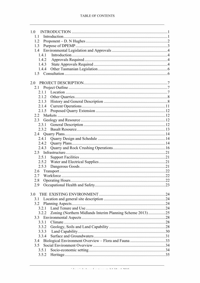
TABLE OF CONTENTS
john miedecke and partners pty ltd March 2019
1.0 INTRODUCTION ...............................................................................................11.1 Introduction.......................................................................................................11.2 Proponent – D. N Hughes .................................................................................21.3 Purpose of DPEMP...........................................................................................31.4 Environmental Legislation and Approvals .......................................................4
1.4.1 Introduction...............................................................................................41.4.2 Approvals Required ..................................................................................41.4.3 State Approvals Required .........................................................................41.4.4 Other Tasmanian Legislation.....................................................................6
1.5 Consultation ......................................................................................................6
2.0 PROJECT DESCRIPTION...................................................................................72.1 Project Outline ..................................................................................................7
2.1.1 Location .....................................................................................................72.1.2 Other Quarries............................................................................................82.1.3 History and General Description ...............................................................82.1.4 Current Operations...................................................................................112.1.5 Proposed Quarry Extension .....................................................................12
2.2 Markets ...........................................................................................................122.3 Geology and Resource ....................................................................................12
2.3.1 General Description .................................................................................122.3.2 Basalt Resource........................................................................................13
2.4 Quarry Plans....................................................................................................142.4.1 Quarry Design and Schedule ...................................................................142.4.2 Quarry Plans.............................................................................................142.4.3 Quarry and Rock Crushing Operations....................................................16
2.5 Infrastructure...................................................................................................212.5.1 Support Facilities .....................................................................................212.5.2 Water and Electrical Supplies..................................................................212.5.3 Dangerous Goods.....................................................................................21
2.6 Transport .........................................................................................................222.7 Workforce .......................................................................................................222.8 Operating Hours..............................................................................................222.9 Occupational Health and Safety......................................................................23
3.0 THE EXISTING ENVIRONMENT..................................................................243.1 Location and general site description .............................................................243.2 Planning Aspects.............................................................................................24
3.2.1 Land Tenure and Use ...............................................................................243.2.2 Zoning (Northern Midlands Interim Planning Scheme 2013) .................25
3.3 Environmental Aspects ...................................................................................283.3.1 Climate.....................................................................................................283.3.2 Geology, Soils and Land Capability ........................................................283.3.3 Land Capability.......................................................................................303.3.4 Surface and Groundwaters.......................................................................31
3.4 Biological Environment Overview – Flora and Fauna ...................................333.5 Social Environment Overview........................................................................34
3.5.1 Socio-economic setting............................................................................343.5.2 Heritage....................................................................................................35

TABLE OF CONTENTS
john miedecke and partners pty ltd March 2019
3.3.3 Aboriginal Heritage .................................................................................35
4.0 ENVIRONMENTAL IMPACTS AND MANAGEMENT...............................364.1 Introduction.....................................................................................................364.2 Potential Environmental Impacts....................................................................364.3 Noise from quarry operations .........................................................................37
4.3.1 Noise studies ............................................................................................374.3.2 Existing Ambient Sound Levels ..............................................................374.3.3 Quarry Site Sound Power Levels.............................................................384.3.4 Predicted Community Sound Levels ......................................................384.3.5 Noise Assessment Criteria ......................................................................414.3.6 Noise Assessment ...................................................................................424.3.7 Conclusions.............................................................................................434.3.8 Management.............................................................................................434.3.9 Assessment of impact ..............................................................................44
4.4 Noise and Vibration from Quarry Blasting.....................................................444.4.1 Introduction..............................................................................................444.4.2 Blast Vibration Limits..............................................................................444.4.3 Determination of Ground Vibration Levels.............................................464.4.4 Fly Rock...................................................................................................504.4.5 Management.............................................................................................514.4.6 Assessment of impact ..............................................................................52
4.5 Dust (particulates)..........................................................................................534.5.1 Issues........................................................................................................534.5.2 Quarry Emissions.....................................................................................534.5.3 Quarry Dust Management........................................................................544.5.4 Assessment of impact ..............................................................................54
4.6 Water Management........................................................................................544.6.1. Issues......................................................................................................544.6.2 Management.............................................................................................554.6.3 Assessment of Impact ..............................................................................56
4.7 Visual Effects..................................................................................................574.7.1 Landscape Setting ...................................................................................574.7.2 Visibility .................................................................................................574.7.3 Management.............................................................................................574.7.4 Assessment of impact ..............................................................................57
4.8 Roads and Traffic...........................................................................................594.8.1 Existing Conditions.................................................................................594.8.2 Proposal Impact ......................................................................................604.8.3 Assessment..............................................................................................604.8.4 Management.............................................................................................604.8.5 Assessment of Impact ..............................................................................60
4.9 Wastes .............................................................................................................604.9.1 Liquid.......................................................................................................604.9.2 Solid Wastes.............................................................................................60
4.10 Greenhouse Gases.........................................................................................604.11 Dangerous Goods..........................................................................................614.12 Land Use .......................................................................................................615.1 Environmental Management...........................................................................625.2 Environmental Monitoring and Review..........................................................62

TABLE OF CONTENTS
john miedecke and partners pty ltd March 2019
6.0 DECOMMISSIONING AND REHABILITATION ..........................................636.1 Existing quarry operations ..............................................................................636.2 Quarry extension.............................................................................................64
6.2.1 Land form.................................................................................................646.2.2 Pasture revegetation .................................................................................646.2.3 Tree and Grass Species suitable for planting...........................................656.2.4 Fertiliser ...................................................................................................656.2.5 Maintenance.............................................................................................656.2.6 Weed control............................................................................................66
7.0 COMMITMENTS ..............................................................................................66
8.0 CONCLUSIONS ................................................................................................66
REFERENCES ............................................................................................................67

TABLE OF CONTENTS
LIST OF FIGURES AND TABLES
Figure No On or Following Page No
1.1 MINING LEASE 2045 P/M LOCATION 1 1.2 QUARRY EXTENSION MINING LEASE 2045 P/M 2 1.3 PLANNING APPROVAL PROCESS 5
2.1 LOCATION 7 2.2 QUARRY EXTENSION AREA 8 2.3 QUARRY OPERATIONS, 1995 9 2.4 QUARRY OPERATIONS, 2005 10 2.5 QUARRY OPERATIONS, 2016 11 2.6: QUARRY LAYOUT CURRENT 11 2.7 QUARRY TOPOGRAPHY 11 2.8 EXISTING QUARRY CLOSURE PLAN 12 2.9 LOCAL GEOLOGY 13 2.10 PIT PLANS STAGE 1 (YEARS 1- 3) 15 2.11 PIT PLANS STAGE 2 (YEARS 3-5) 15 2.12 PIT PLANS STAGE 3 (YEARS 5-10 +) 15 2.13 PIT PLANS - CROSS SECTIONS A – A 15 2.14 PIT PLANS - CROSS SECTIONS B – B 15 2.15 REHABILITATION PROFILE 15 2.16 THREE D PERSPECTIVE YEAR 10 16 2.17 PROCESSING FLOW CHART – AGGREGATE 18 2.18 PROCESSING FLOW CHART – ROAD BASE 18 2.19 PRECOAT PLANT AREA 20
3.1 LAND TENURE QUARRY EXTENSION AREA. 24 3.2 LAND ZONING QUARRY EXTENSION AREA. 25 3.3 ZONING – SPECIAL AREAS 26 3.4 RAINFALL/ EVAPORATION 28 3.5 WIND DIRECTIONS 28 3.6 SOIL ASSOCIATIONS 30 3.7: LAND CAPABILITY 30 3.8: SURFACE WATER CATCHMENTS 31 3.9 SURFACE WATER CATCHMENTS LIDAR 32 3.10: GROUNDWATER BORES 33 3.11: VEGETATION 34
4.1 QUARRY SITE AND MONITORING POSITIONS 37 4.2 CURRENT OPERATIONS – ACOUSTIC MODEL 38
INPUTS – GROUND CONTOURS 4.3 CURRENT OPERATIONS – PREDICTED NOISE 38
CONTOURS 4.4 YEAR 2 ACOUSTIC MODEL INPUT 40 4.5 GROUND VIBRATION CONTOURS 47

TABLE OF CONTENTS
4.6 WORST-CASE AIRBLAST CONTOURS FROM A 49 STANDARD BLAST
4.7 FLYROCK EXCLUSIONS ZONE 51 4.8 WATER MANAGEMENT PLAN 56
6.1 QUARRY CONCEPTUAL CLOSURE PLAN 64
Table No Page No
2.1 Areas Disturbed, Topsoil And Overburden Volumes 17
2.2 List Of Equipment 21
3.1 Compliance with standards 26 3.2 Water Quality 31
4.1 Summary of Community Noise Levels 38 4.2 Quarry Sound Power Levels 38 4.3 Predicted Community Noise Levels 41 4.4 Daytime Noise Limit, dBA, for Other Quarries 42 4.5 Predicted Sound Pressure Levels at Nearby 43
Residences and Assessment 4.6 Australian Standard 2187.2-2006 - Table J4.5(B) 45
Recommended Ground Vibration Limits for Control of Damage to Structures
4.7 Blast specifications used in analysis 46 4.8 Estimated ground vibration levels 48 4.9 Distances to milestone airblast levels for standard 49
specification blasts 4.10 Distances of Flyrock and Clearance Zone 51 4.11 Retention/Sediment Pond Sizes 56
5.1 Monitoring Program 63
6.1 Table of Commitments 66

TABLE OF CONTENTS
List of Appendices
Appendix A: EMP Guidelines
Appendix B: Terry Eaton Traffic Assessment
Appendix C: BIS Policies
Appendix D:. NVC Noise Assessment
Appendix E: Terrock Blasting Assessment
Appendix F: Weed and Hygiene Guidelines

D.N.Hughes Western Junction Quarry Extension DPEMP
john miedecke and partners pty ltd March 2019
1
1.0 INTRODUCTION
1.1 Introduction The quarrying industry in Tasmania provides a reliable supply of construction materials for concrete manufacture, road making, building construction, and the maintenance of the existing road network on which the public and other industries depend.
Mr D Hughes is a local landowner who has owned a quarry on his land since approximately 1980. The existing Mining Lease (ML 975 P/M), mining lease application (2045 P/M) and the permit (Licence to Operate Scheduled Premises 3374) are all in his name.
The Western Junction Quarry at near Breadalbane in Northern Tasmania produces a wide range of construction materials. (Figure 1.1).
FIGURE 1.1: MINING LEASE 2045 P/M LOCATION – Western Junction Tasmania
Proposed Quarry extension site

D.N.Hughes Western Junction Quarry Extension DPEMP
john miedecke and partners pty ltd March 2019
2
Since 1982 the quarry has been operated by Brambles (now Bis Quarries Pty Ltd) under an agreement between Brambles (now Bis) and Mr Hughes.
Bis operates under the Mining Lease No. 975 P/M granted by the Tasmanian Department of Mines (now Mineral Resources Tasmania) and Environmental Licence (Scheduled Premises Licence No. 3374) approved by the Tasmanian Department of Primary Industries, Water and Environment (DPIWE) for its operation. Licence 3374 permits the extraction, crushing and screening of 355,000 tonnes per annum (196,875 m3 at an SG of 1.6t/m3) of basalt and the operation of the quarry is consistent with local government zoning. The quarry is operated in accordance with an Environmental Management Plan (EMP) Operations completed in 2010 (Miedecke, 2012).
As basalt rock reserves are being depleted in the existing mining lease. Mr Hughes has applied for an additional mining lease (MLA 2045P/M (20.15ha) (Figure 1.2) to allow the continuation of the quarry activities. Mr Hughes currently owns and farms the land where the mining lease is proposed.
The quarry has been in operation for over 30 years and provides a wide selection of construction and building materials essential for regional development without any significant adverse environmental effects. It is also well located to provide construction materials being situated in close proximity to a major road network, close to Launceston, in an isolated area of private land well screened from residences and local views. It is an important supplier to the civil construction industry in Northern Tasmania and has supplied to both the north-west and East Coasts. The area currently has three operating quarries.
The proximity of the quarry to the Launceston Metropolitan Area and markets also enables product costs to remain low as a supplier of road materials and concrete aggregate.
Mr Hughes is applying for a level 2 permit at a production level of 312,500 cubic metres of product per annum or 500,000 tones per annum (at a SG of 1.6t/m3). This will provide future long term production within the new area proposed and allow the operation to be extended for in excess of 18 years' from its current lifespan.
1.2 Proponent – D. N Hughes The proponent for the Quarry is the existing land owner, Mr David Hughes. Under an agreement, Bis is the operator.
The contact for the project are: David Hughes “The Springs” RSD 619 Breadalbane TAS 7258 T 043891813 Email: [email protected] and Bis Industries Tim Shegog - Operations Manager - Northern Western Junction Quarry, 1A Richard Street, Western Junction , TAS 7212 T +61 3 6398 9005 M 0407 871 568 www.bisindustries.com Email: [email protected]

FIGURE 1.2 QUARRY EXTENSION MINING LEASE 2045 P/M
��������������������� �����
��
����
�����
����
�����
����
�����
���������������������������
����
��������
��������
���������
���������
�������
������
��!���������
�������������
���������������������
����"
������#�$����������������������� �"
�!�����������������������"�
�����%�!����$
�����$�����!���������� "�
�&'�����������$�����������"�
���#������������"�
#����������#�$����
�����%�!
����$
�&'�����������$�����������"�
������
� �������
��(�������!������������"�
�(����������
����
������
�� �� � � ���
�!�(�$������
%�!��������%$�#�$����������������$������������������!%'�������������!�(�$�
��������������������������������������������������)������������� ����
�� ���������� �� ������������
�� ��������
���� !
"#$���%� ���&�'�����"()�*+��,(-��
��(.��
"-/ ��(- �-�0"�+(�,�
0����'�������1 �����2�
����!�3�������4'�������5' ���+��6���&��������#� ���-7�������
8���9��0���&�� ���� ���*��/�����"#$�� ����8�
�����������������
� :�:�� ;��������'�
�!2 ����� <�&� �&=%��6��&���2; 7����� >���>
>?����������"� &�@�-'����� ����������1��6����
��%����>����>���A
�:���2%����&��# ��@�#��&��B ���@�������8�% ���
�������������������
�������������������

D.N.Hughes Western Junction Quarry Extension DPEMP
john miedecke and partners pty ltd March 2019
3
Bis Industries is a leading provider of specialised logistics and materials handling solutions to the world’s biggest mining and resources companies. With over a century of experience, they combine in house equipment design with expert maintenance, management and an established parts supply chain to support the processing, handling and hauling of millions of tonnes of materials across Australia and Indonesia. Major services offered include off-road load and haul, underground equipment services, specialised on-road logistics management, large scale infrastructure, crushing, mineral extraction and on-site services.
In Tasmania, operating under the wholly owned Bis Quarries Pty Ltd, they operate a number of major quarries and sand pits supplying the construction industry, State and Local Government.
1.3 Purpose of DPEMP Mr Hughes is applying for a permit and mining lease for an extension to the existing quarrying operations. This DPEMP has been prepared to supply the Northern Midlands Council, Mineral Resources Tasmania (MRT), the Environment Protection Authority (EPA), the Department of Primary Industry, Parks, Water and Environment (DPIPWE), other Government Departments, residents in the area and the general community with the following information;
• description of the proposal;• description of the area's environment;• the possible environmental impacts; and• the proposed environmental management controls for the project.
The guidelines issued by DPIPWE), (EPA) for the DPEMP are in Appendix A.
The continued operations of the quarry and crushing activity is expected to supply the building and construction industry market at a rate of up to 312,500 cubic metres of crushed rock per year. This classifies the proposal as a level 2 activity under Schedule 2 Subsections 5(a) and 6(a) (ii) of the Environmental Management and Pollution Control Act 1994(EMPCA being;
5. Extractive Industries(a) Quarries: the extraction of any rock or gravel and producing 5000 cubic metres or more of rock or gravel per year. 6. Materials Handling(a) Crushing, Grinding or Milling: processing (by crushing, grinding, milling or separating into different sizes by sieving, air elutriation or in any other manner) of – (ii) rock, ores or minerals at a rate in excess of 1000 cubic metres per year.
The development and operation of the quarry, crushing and screening plant will be in accordance with this Development Proposal and Environmental Management Plan (DPEMP) and will be controlled by the provisions of the Environmental Management and Pollution Control Act 1994, the Mineral Resources Development Act, 1995, the Workplace Health and Safety Act 1995, associated Acts and Regulations, the terms and conditions of the Mining Lease and the Permit conditions. The quarry code of practice is the code which will be followed in quarry operations (EPA, 2017).

D.N.Hughes Western Junction Quarry Extension DPEMP
john miedecke and partners pty ltd March 2019
4
1.4 Environmental Legislation and Approvals 1.4.1 Introduction
Quarrying requires environmental and planning approvals from the Tasmanian government in order to proceed with the operations. These are outlined below.
The Commonwealth Environment Protection and Biodiversity Conservation Act 1999 (EPBCA), in force since 16 July 2000, enables the Commonwealth to join with the states and territories to provide a national scheme of environment protection and biodiversity conservation. This Act identifies seven matters of national environmental significance:
• World Heritage properties• National heritage places (from 1 January 2004)• Ramsar wetlands of international significance• Threatened species and ecological communities• Migratory species• Commonwealth marine area• Nuclear actions (including uranium mining)
There were no matters that relate to the act identified to the extension or proposed quarry.
1.4.2 Approvals Required 1.4.3 State Approvals Required
The Tasmanian environmental and planning assessment and approval process for a development application is shown in Figure 1.3.
• Environmental Management and Pollution Control Act 1994 (EMPCA).
The application for environmental approval is part of an application made to the local planning authority under the Land Use Planning and Approvals Act (LUPAA). The environmental approval process centres on the Environmental Impact Assessment (EIA) to be prepared by the Board of the Environmental Protection Authority (EPA) under sections 73 and 74 of the EMPCA.
The Director of the EPA has advised Mr Hughes that the proposed Project development is considered a Level 2 activity in accordance with EMPCA Schedule 2, and guidelines for preparation of the DPEMP were provided (see Appendix A).
After submission of the planning permit application (which includes this DPEMP and supporting documentation) and its referral by the Planning Authority, i.e. the Northern Midlands Council, to the EPA, the DPEMP is placed on public display. The EPA assesses the resulting public comments and in conjunction with its own assessment of the document, prepares a report that is considered by the Board. The Board then notifies the Planning Authority of conditions that need to be incorporated in the planning permit or directs the Planning Authority to refuse to grant a permit.

D.N.Hughes Western Junction Quarry Extension DPEMP
john miedecke and partners pty ltd March 2019
5
EIA Process for Class 2B/2C Assessments (where DPEMP is required)
Preliminary discussions between proponent, EPADivision and planning authority
Proponent submits Notice of Intent
DPEMP Project Specific Guidelines developed(may include public consultation for larger projects)
Proponent prepares draft DPEMP in consultation with EPA Division and planning authority
Permit application and referral to EPA Board (including final DPEMP)
Request for further information from proponent(if required)
Public and agency consultation on permit application(including DPEMP)
Proponent prepares DPEMP Supplement(if required)
Environmental Assessment Report prepared
EPA Board and planning authority determinations
Appeals (if applicable)
FIGURE 1.3: PLANNING APPROVAL PROCESS
Mr Hughes has also made a Mining Lease Application (MLA) to Mineral Resources Tasmania (see Section 3). This covers the area of the proposed quarry.
The key legislation is:
• Land Use Planning and Approvals Act 1993 (LUPAA).
D.N.Hughes Western Junction Quarry Extension DPEMP
john miedecke and partners pty ltd March 2019
6
1.4.4 Other Tasmanian Legislation
In addition to the legislation governing the environmental and planning process, the following list of Tasmanian legislation has been assessed in the preparation of the DPEMP, and their relevant statutory or regulatory requirements as identified in this DPEMP have been or will be observed:
• Aboriginal Relics Act 1975.• Crown Lands Act 1976.• Dangerous Goods Act 1998 and Regulations.• Fire Services Act 1979.• Forest Practices Act 1985.• Historic Cultural Heritage Act 1995.• Inland Fisheries Act 1995.• Local Government (Building and Miscellaneous Provisions) Act 1993.• National Environment Protection Council (Tasmania) Act 1995.• National Parks and Reserves Management Act 2002.• Nature Conservation Act 2002.• Regional Forest Agreement 1997.• Threatened Species Protection Act 1995.• Mineral Resources Development Act 1995.• Water Management Act 1999.• Weed Management Act 1999.• Workplace Health and Safety Act 1995.
There are other state policies and strategies. These include the Policy on Water Quality Management (2009).
The most relevant, although it has no statutory basis, is the Quarry Code of Practice (EPA 2017). This document is designed to give guidance to the operators of quarries, sand pits and extractive pits.
1.5 Consultation Bis and its consultants, during site studies and project planning, have consulted widely with state and local government authorities, including Mineral Resources Tasmania (MRT), EPA (Department of Primary Industries Parks, Water and Environment (DPIPWE)), Launceston Airport management, Northern Midlands Council and local residents in proximity to the quarry.

D.N.Hughes Western Junction Quarry Extension DPEMP
john miedecke and partners pty ltd March 2019
7
2.0 PROJECT DESCRIPTION
2.1 Project Outline 2.1.1 Location
The existing quarry is near Western Junction, NE of the Launceston Airport (Figure 1.1).
The Western Junction Quarry is sited on the eastern side of a moderately high escarpment formed from Tertiary basalt, rising above the north-south flowing valley formed by Rose Rivulet, a tributary of the North Esk River, between the townships of Relbia and Breadalbane in the Northern Midlands municipal area.
The ridgeline, on which the quarry is situated, rises to a prominence of RL 222 at Cocked Hat Hill, about 1.75km to the north west of the quarry.
A more detailed location map (Google earth image) is shown in Figure 2.1.
FIGURE 2.1: LOCATION – Western Junction Tasmania The quarry and extension are located north -east of the Airport and due south of quarries at Mt Oriel and Raeburn. The Josef Chromy Vineyard is immediately to the

D.N.Hughes Western Junction Quarry Extension DPEMP
john miedecke and partners pty ltd March 2019
8
NE. The existing quarry has been developed in an eastern direction and as a “pit” (ie sunken into the ground surface). As a result, it has only limited visibility to the east and is not visible from other directions.
The proposed quarry extension will extend the quarry to the west and towards the airport (Figure 1.2 and 2.2).
FIGURE 2.2: QUARRY EXTENSION AREA. SOURCE ; Google Earth.
2.1.2 Other Quarries
The Western Junction Quarry was the first in the area, having commenced in 1982. There are three other more recent quarries in the area, immediately to the North. These are the Stornoway “Raeburn Quarry” , McGraths Quarry and the Mount Oriel Breadalbane Pty Ltd “Cocked Hat Hill Quarry”.
Both have permitted production levels of 312,500 m3 per year. Their locations are shown in Figure 2.1. These two quarries are located 1 to 1.5km to the north (and mostly upwind) of the Bis quarry, with agricultural land between. While these quarries share access off West Hobart Road, there is no common access with the Bis quarry.
Therefore there is no need for any requirement to coordinate any operational activities with the Western Junction Quarry.
2.1.3 History and General Description
For many years the Western Junction Quarry has been one of the largest operating in Northern Tasmania. Brambles had operated the quarry at the site since 1982, until Bis took ownership in 2007, essentially under the same management team.

D.N.Hughes Western Junction Quarry Extension DPEMP
john miedecke and partners pty ltd March 2019
9
Operations commenced in 1982 approximately, with the initial quarrying on a pit to the south of Briarly Creek, where the processing plant is now located. Operations were eventually transferred to the north of the Creek. An aerial photograph taken in 1995 (see Figure 2.3 below), show operations with the active quarry at that time to the north of the Creek (“Far Pit”).
FIGURE 2.3: QUARRY OPERATIONS, 1995. SOURCE ; Miedecke 2012.
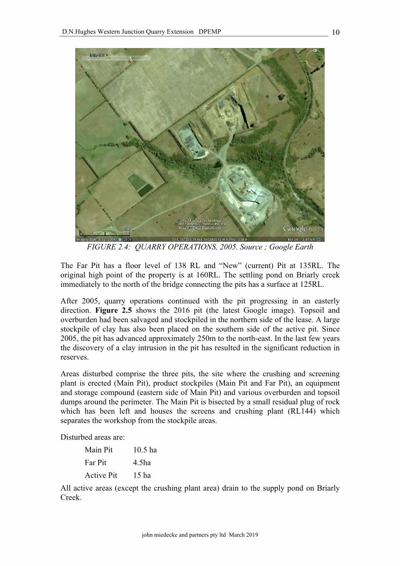
By 2005 quarry operations had been completed within the Far Pit area and operations transferred to a new pit to the east (New Pit in Figure 2.3 – the current pit). Figure 2.4 shows the 2005 pit. All pits are fringed by large stockpiles of topsoil and overburden materials.
The existing workings occupied an area of approximately 25.7 Ha in 2005. There were three pit areas, the Main Pit to the south of Briarly Creek and the Far Pit and Current Pit on the northern side of the creek. Main Pit has a floor level of 132 RL, and is now the site of the crushing and screening plant.
D.N.Hughes Western Junction Quarry Extension DPEMP
john miedecke and partners pty ltd March 2019
10
FIGURE 2.4: QUARRY OPERATIONS, 2005. Source ; Google Earth
The Far Pit has a floor level of 138 RL and “New” (current) Pit at 135RL. The original high point of the property is at 160RL. The settling pond on Briarly creek immediately to the north of the bridge connecting the pits has a surface at 125RL.
After 2005, quarry operations continued with the pit progressing in an easterly direction. Figure 2.5 shows the 2016 pit (the latest Google image). Topsoil and overburden had been salvaged and stockpiled in the northern side of the lease. A large stockpile of clay has also been placed on the southern side of the active pit. Since 2005, the pit has advanced approximately 250m to the north-east. In the last few years the discovery of a clay intrusion in the pit has resulted in the significant reduction in reserves.
Areas disturbed comprise the three pits, the site where the crushing and screening plant is erected (Main Pit), product stockpiles (Main Pit and Far Pit), an equipment and storage compound (eastern side of Main Pit) and various overburden and topsoil dumps around the perimeter. The Main Pit is bisected by a small residual plug of rock which has been left and houses the screens and crushing plant (RL144) which separates the workshop from the stockpile areas.
Disturbed areas are: Main Pit 10.5 ha Far Pit 4.5ha Active Pit 15 ha
All active areas (except the crushing plant area) drain to the supply pond on Briarly Creek.
D.N.Hughes Western Junction Quarry Extension DPEMP
john miedecke and partners pty ltd March 2019
11
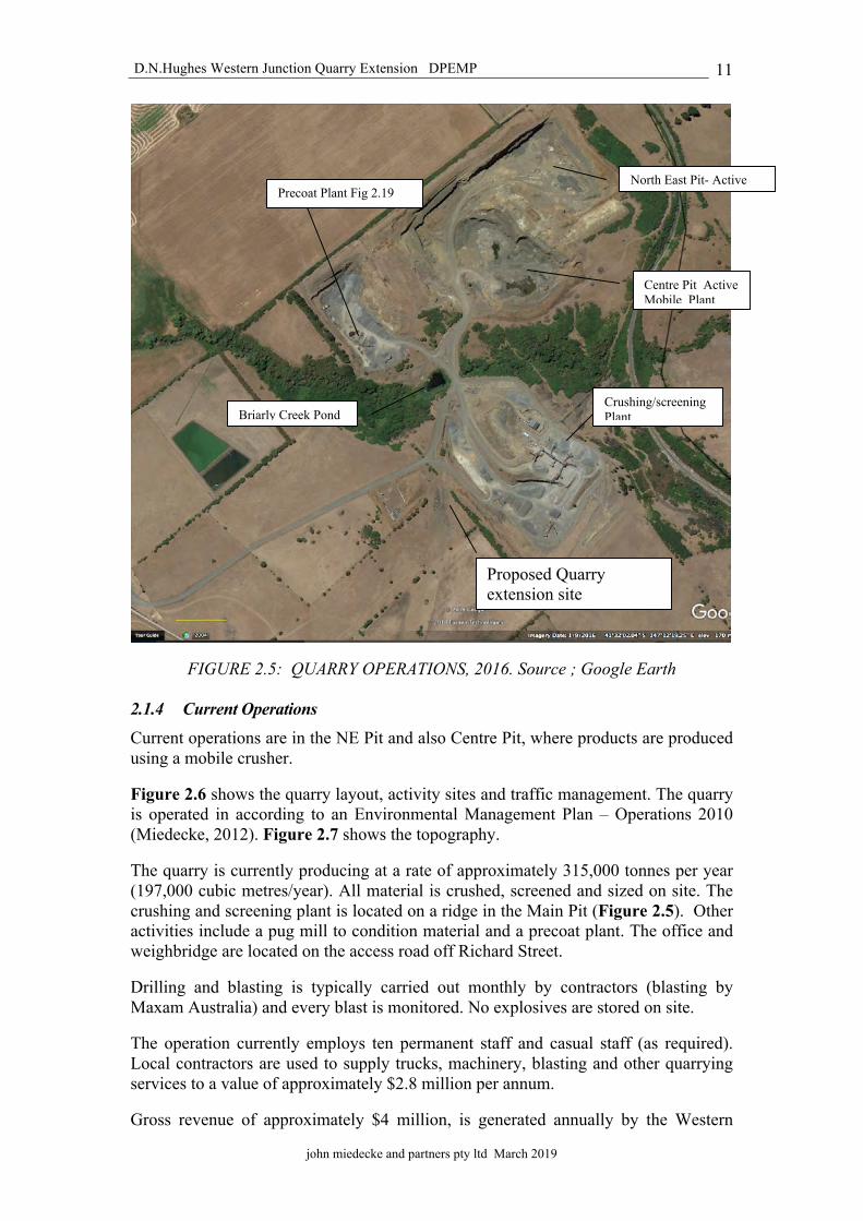
FIGURE 2.5: QUARRY OPERATIONS, 2016. Source ; Google Earth
2.1.4 Current Operations
Current operations are in the NE Pit and also Centre Pit, where products are produced using a mobile crusher.
Figure 2.6 shows the quarry layout, activity sites and traffic management. The quarry is operated in according to an Environmental Management Plan – Operations 2010 (Miedecke, 2012). Figure 2.7 shows the topography.
The quarry is currently producing at a rate of approximately 315,000 tonnes per year (197,000 cubic metres/year). All material is crushed, screened and sized on site. The crushing and screening plant is located on a ridge in the Main Pit (Figure 2.5). Other activities include a pug mill to condition material and a precoat plant. The office and weighbridge are located on the access road off Richard Street.
Drilling and blasting is typically carried out monthly by contractors (blasting by Maxam Australia) and every blast is monitored. No explosives are stored on site.
The operation currently employs ten permanent staff and casual staff (as required). Local contractors are used to supply trucks, machinery, blasting and other quarrying services to a value of approximately $2.8 million per annum.
Gross revenue of approximately $4 million, is generated annually by the Western
North East Pit- Active
Proposed Quarry extension site
Centre Pit Active Mobile Plant
Crushing/screening Plant
Precoat Plant Fig 2.19
Briarly Creek Pond

Figure 2.6 Western Junction Quarry Layout 1

FIGURE 2.7: QUARRY TOPOGRAPHY – LIDAR Source: The list

D.N.Hughes Western Junction Quarry Extension DPEMP
john miedecke and partners pty ltd March 2019
12
Junction Quarry.
As discussed in the previous section, in recent years the current operations have concentrated on the NE section of the lease and reserves are rapidly depleting, to the extent that Bis estimate that there are approximately 2-3 years production remaining on the existing mining lease 975 P/M.
All of the areas to the north of Briary Creek will be progressively rehabilitated in accordance with the EMP – Operations. The planned final land use, as required by the landowner, Mr Hughes, is for areas to be level within the pits, where possible. These areas may be used for light industries in future applications. The benches will be revegetated with native trees. Figure 2.8 shows the closure and rehabilitation plan
Bis have conducted exploration drilling on the private grazing land to the west of the existing original pit (and processing plant location) and this has confirmed a viable basalt resource for future quarrying ( see Section 2.1.5 .
A new mining lease application has been made over this area and this is the area proposed for the quarry extension (Figure 2.2).
2.1.5 Proposed Quarry Extension Bis propose to complete the existing quarry operations north of Briarly Creek, with rock production transferred gradually to the new site (ML 2045 P/M), as shown in Figures 2.2, with a potential increase in production to 500,000 tonnes per year (312,500 m3 at an SG of 1.7t/m3).
The pit will be developed in a south - westerly direction from the current (Main) Pit floor in approximately 12 metre deep benches, and developed in stages with topsoils/subsoils stripped and stockpiled ahead of the rock blasting and removal. This will provide a bund approximately 250 metres from the aerodrome at the closest point of the Mining Lease.
Rainfall falling on disturbed areas will be directed to a series of retention ponds prior to discharge to the water supply pond in Briarly Creek.
The existing crushing plant will continue to be used and there are no plans for additional equipment. The proposal merely represents a new location for the rock source for ongoing quarry operations to the new ML.
2.2 Markets The quarry provides a combination of screened and crushed basalt rock for markets in Northern Tasmania. In addition, the quarry has the capability of supplying bulk fill for road, building and civil construction.
2.3 Geology and Resource Mineral Resources Tasmania have reported on the basalt resources of the area (MRT, 2008) and this is used as a basis of this section.
2.3.1 General Description
Basalt is distributed over an area of about nine square kilometers near Breadalbane and Western Junction. Land uses in the area include quarry operations and their associated buffer and future resource areas, various residential, light industrial and

PossibleFuture
Development Post 2015
Visual Bund or remnant surfaceRevegetated with tress/ grass
Western pitLevel, graded and compacted surface
Area 28000m2.
Subject to detail assessment and design followingcompletion.
Existing Plant AreaLevel, graded and compacted surface
Area 73,000m2.
Centre pitLevel, graded and compacted surface
Area 57000m2.
North East pitLevel, graded and compacted surface
Area 48000m2.
November 2015
JOHN MIEDECKE AND PARTNERS PTY LTD
BISIndustrialLogistics/D.N.Hughes
F I G . 2.8
Western Junction QuarryConcept Closure Plan
Water body
Rehabilitated areatrees/ shrubs/ grassess

D.N.Hughes Western Junction Quarry Extension DPEMP
john miedecke and partners pty ltd March 2019
13
rural developments. Launceston airport is also situated on the basalt.
The basalt is of late Eocene age and for the main part the basalt overlies a succession of older Eocene to Palaeocene age mudstone, siltstone and sandstone with minor lignite and conglomerate that was deposited in a graben or half-graben structure. To the west the basalt laps onto Jurassic dolerite that forms a horst structure. The same dolerite probably underlies the Palaeogene deposits within the graben.
It is possible that the basalt was once buried by sedimentary strata that were subsequently removed by erosion, however small pockets of sedimentary deposits may still exist above the basalt. These strata may include mudstone, sandstone and possibly gravel deposits.
In a generalised way the base of the basalt falls topographically from the exposed dolerite in the west towards the east where the valley of Rose Rivulet and its tributaries have eroded into the sedimentary strata and the overlying basalt by backwards retreat.
Estimates of basalt thickness can be made based on the structural contours drawn on the base of the basalt. Additional control points come from a handful of water bores and quarry excavations where the quarries have passed through the base of the basalt and more recently from quarry resource and planning drill holes. Two exploration bores drilled south of the Stornoway (Raeburn) Quarry in September 2008 can also be used to gauge the basalt thickness as well. Figure 2.9 shows the geology in the general area of the Stornoway and Bis quarries.
The basalt is not a uniform rock and this has enabled the quarry operations to produce a range of products, some derived from relatively hard un-weathered basalt, to products derived from weathered or altered rock. Contraction cooling joints occur through much of the basalt and these define columns of various diameters and inclinations. Some basalt is massive and some is vesicular or amygdaloidal containing zeolite. In recent years the basalt has been recognised to be a composite body composed of at least two separate lava flows with intervening sedimentary rocks including clayey siltstone, sandstone and conglomerate.
A review of the data has been used to infer structural contours on the base of the basalt although most of the data has deficiencies and more drilling is probably required to provide further data that might help define the basal geometry of the basalt.
The quarry exposures provide information about the structural form of the basalt and associated rocks and the variable nature of the rock weathering state. Some basalt is hard, grey and relatively less weathered or altered compared to other brown-coloured basalt. Some of the latter basalt is considered to have undergone alteration during the period of vulcanicity and some of the weathered/altered rocks that resemble a basalt flow instead may be tuffaceous or fragmental.
2.3.2 Basalt Resource
Of the large area of basalt that occurs in the Breadalbane-Western Junction area, probably less than 20% by area of the surface exposed basalt is contained within mining leases. Taken as a whole the basalt may exceed 70-80m thickness at places such as Cocked Hat Hill, but more applicable is a general thickness range of 20 – 40

D.N.Hughes Western Junction Quarry Extension DPEMP
john miedecke and partners pty ltd March 2019
14
m that can be estimated from previous mapping of the basalt lower surface at the periphery of the basalt and by using some water bore information.
Within the Stornoway and Bis leases the basalt thickness is similarly variable in thickness and may range approximately 10 – 40 m thickness. The basalt is variable in character and this variability enables a number of different commodities to be obtained from the quarries. This variability also means the extent of any one basalt type similarly cannot be determined without knowledge of the controlling geological factors in combination with some subsurface information to place limits on the rock distribution.
The September 2008 exploratory drilling south of the Stornoway quarry has also detected thick sedimentary clay where previously basalt had been shown on geological maps.
In view of the presence of these sedimentary units, the estimation of resources is further complicated as they may both reduce in volume the expected basalt resource or hinder the quarrying of existing resource. Quarry management in the short term and over the life of the leases will need to take the variability of the rock and clay distribution into account.
Bis has drilled a number of rotary air blast holes within the extension area and this has confirmed the basalt resource. This has variable depths of overburden cover. A base of 130m RL is the base of the resource in the plant area (the original pit ) and a resource of approximately 9 million tonnes of basalt has been identified. This will provide over 18 Years production at a rate of 500,000 tonnes per year.
2.4 Quarry Plans 2.4.1 Quarry Design and Schedule
Quarrying will be undertaken in accordance with the Permit and Mining Lease conditions. the Quarry Code of Practice, which has been developed by the Department of Primary Industries Water and Environment, Mineral Resources Tasmania and the quarry industry in 1999. The latest edition ( 3rd) was revised in 2017 ( EPA, 2017).
The quarry activities will be similar to what has happened to date and will involve the following:
• Site preparation (vegetation clearing, topsoil and overburden stockpiling);• Gravel and unconsolidated basalt removal by dozer and/or excavator and
trucks;• Rock drilling and blasting;• Rock removal using rubber tyred loaders and/or excavators;• Transport of rock to the existing crushing and screening plant;• Rock crushing and screening;• Stockpiling of crushed rock; and• Transporting of materials to markets.
2.4.2 Quarry Plans
Figure 2.7 shows a topographic plan of the existing quarry area.
D.N.Hughes Western Junction Quarry Extension DPEMP
john miedecke and partners pty ltd March 2019
15
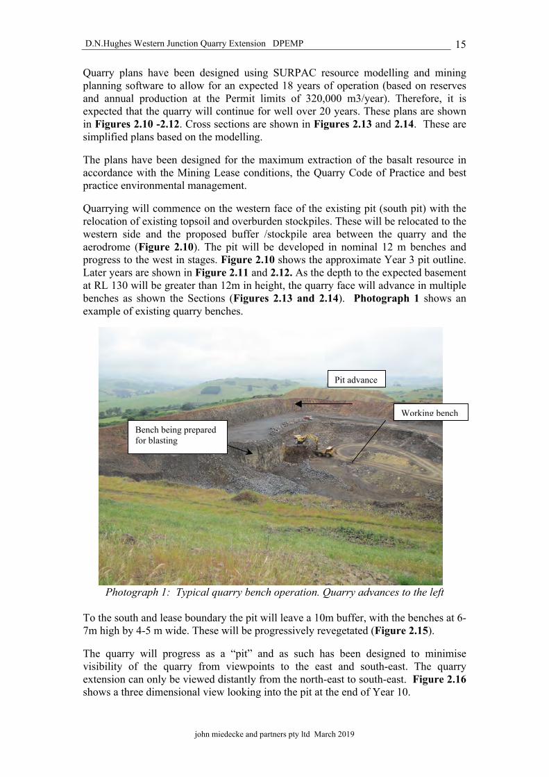
Quarry plans have been designed using SURPAC resource modelling and mining planning software to allow for an expected 18 years of operation (based on reserves and annual production at the Permit limits of 320,000 m3/year). Therefore, it is expected that the quarry will continue for well over 20 years. These plans are shown in Figures 2.10 -2.12. Cross sections are shown in Figures 2.13 and 2.14. These are simplified plans based on the modelling.
The plans have been designed for the maximum extraction of the basalt resource in accordance with the Mining Lease conditions, the Quarry Code of Practice and best practice environmental management.
Quarrying will commence on the western face of the existing pit (south pit) with the relocation of existing topsoil and overburden stockpiles. These will be relocated to the western side and the proposed buffer /stockpile area between the quarry and the aerodrome (Figure 2.10). The pit will be developed in nominal 12 m benches and progress to the west in stages. Figure 2.10 shows the approximate Year 3 pit outline. Later years are shown in Figure 2.11 and 2.12. As the depth to the expected basement at RL 130 will be greater than 12m in height, the quarry face will advance in multiple benches as shown the Sections (Figures 2.13 and 2.14). Photograph 1 shows an example of existing quarry benches.
Photograph 1: Typical quarry bench operation. Quarry advances to the left
To the south and lease boundary the pit will leave a 10m buffer, with the benches at 6-7m high by 4-5 m wide. These will be progressively revegetated (Figure 2.15).
The quarry will progress as a “pit” and as such has been designed to minimise visibility of the quarry from viewpoints to the east and south-east. The quarry extension can only be viewed distantly from the north-east to south-east. Figure 2.16 shows a three dimensional view looking into the pit at the end of Year 10.
Working bench
Bench being prepared for blasting
Pit advance

5401
600.
054
0180
0.0
5402
000.
0
5402
200.
054
0240
0.0
517000.0 517200.0 517400.0
517400.0
517600.0
517600.0 517800.0 518000.0
100 0 100 200 m0 200m
Existing crushing andscreening plant
Settling /water supply pond
All quarry outlines indicative only. Subjectto geology and detail design
Stage 1 Years 0-3Extend quarry wall to west thenadvance to north. Base RL130
Soil/overburdenstockpile area
JOHN MIEDECKE AND PARTNERS PTY LTD
Bis Western Junction Quarry Extension
F I G . 2.10
Stage 1 (years 1- 3) Google Image
A
B
A A
B

5401
600.
054
0180
0.0
5402
000.
0
5402
200.
054
0240
0.0
517000.0 517200.0 517400.0
517400.0
517600.0
517600.0 517800.0 518000.0
100 0 100 200 m0 200m
Existing crushing andscreening plant
Settling /water supply pond
All quarry outlines indicative only. Subjectto geology and detail design
Stage 2 Years 3-5Advance quarry base RL 130 to
north west
Soil/overburdenstockpile area
JOHN MIEDECKE AND PARTNERS PTY LTD
Bis Western Junction Quarry Extension
F I G . 2.11
Stage 2 (years 3- 5) Google Image
A
B
A A
B

5401
600.
054
0180
0.0
5402
000.
0
5402
200.
054
0240
0.0
517000.0 517200.0 517400.0
517400.0
517600.0
517600.0 517800.0 518000.0
100 0 100 200 m0 200m
Existing crushing andscreening plant
Settling /water supply pond
All quarry outlines indicative only. Subjectto geology and detail design
Stage 3 Years 5 - 10Advance quarry upper benchbase RL 142 to north west
Benches indicative only
RL142
Benchadvance
Soil/overburdenstockpile area
Stage 4 Years +10Advance quarry benches
JOHN MIEDECKE AND PARTNERS PTY LTD
Bis Western Junction Quarry Extension
F I G . 2.12
Stage 3 (years 5- 10) Google Image
A
B
A A
B

13

Year 1
Year 5 Final
Existing surface
A
JOHN MIEDECKE AND PARTNERS PTY LTD
Bis Western Junction Quarry Extension
F I G . 2.14
Pit Plans - Cross Sections B - B
BYear 3
Year 10 &
B

protective bund
overburden 0.5m with topsoil 0.2m- then revegetation
Quarry floor left as level as practical - grade 1% to the east
- then compacted base
6m
6m
4-5m
Diagramatic Only
4-5m
Quarry walls final profile, with12m benches halfed
JOHN MIEDECKE AND PARTNERS PTY LTD
Bis Western Junction Quarry Extension
2.15F I G .
Typical Rehabilitation Profile - Quarry Walls
D.N.Hughes Western Junction Quarry Extension DPEMP
john miedecke and partners pty ltd March 2019
16
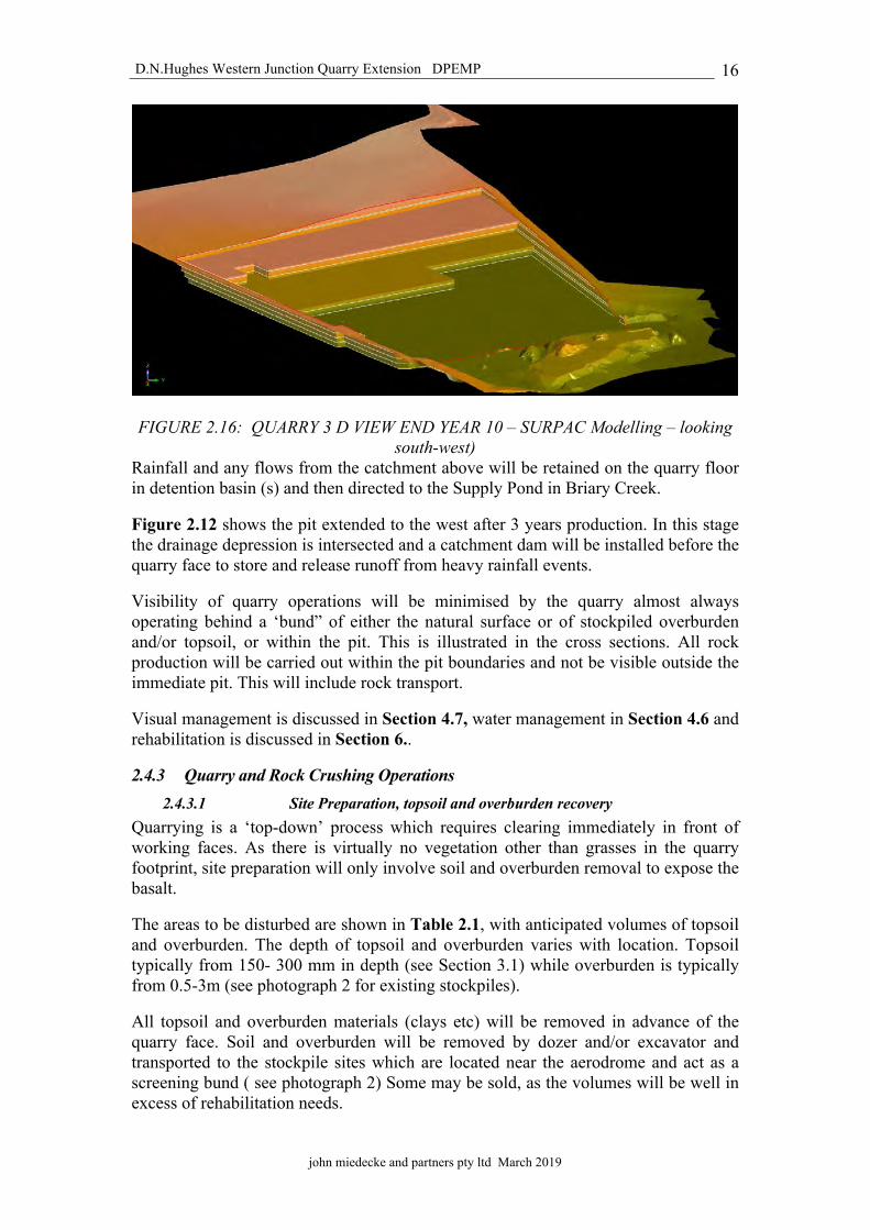
FIGURE 2.16: QUARRY 3 D VIEW END YEAR 10 – SURPAC Modelling – looking south-west)
Rainfall and any flows from the catchment above will be retained on the quarry floor in detention basin (s) and then directed to the Supply Pond in Briary Creek.
Figure 2.12 shows the pit extended to the west after 3 years production. In this stage the drainage depression is intersected and a catchment dam will be installed before the quarry face to store and release runoff from heavy rainfall events.
Visibility of quarry operations will be minimised by the quarry almost always operating behind a ‘bund” of either the natural surface or of stockpiled overburden and/or topsoil, or within the pit. This is illustrated in the cross sections. All rock production will be carried out within the pit boundaries and not be visible outside the immediate pit. This will include rock transport.
Visual management is discussed in Section 4.7, water management in Section 4.6 and rehabilitation is discussed in Section 6..
2.4.3 Quarry and Rock Crushing Operations 2.4.3.1 Site Preparation, topsoil and overburden recovery
Quarrying is a ‘top-down’ process which requires clearing immediately in front of working faces. As there is virtually no vegetation other than grasses in the quarry footprint, site preparation will only involve soil and overburden removal to expose the basalt.
The areas to be disturbed are shown in Table 2.1, with anticipated volumes of topsoil and overburden. The depth of topsoil and overburden varies with location. Topsoil typically from 150- 300 mm in depth (see Section 3.1) while overburden is typically from 0.5-3m (see photograph 2 for existing stockpiles).
All topsoil and overburden materials (clays etc) will be removed in advance of the quarry face. Soil and overburden will be removed by dozer and/or excavator and transported to the stockpile sites which are located near the aerodrome and act as a screening bund ( see photograph 2) Some may be sold, as the volumes will be well in excess of rehabilitation needs.

D.N.Hughes Western Junction Quarry Extension DPEMP
john miedecke and partners pty ltd March 2019
17
Table 2.1: Areas Disturbed, Topsoil And Overburden Volumes
Stage
Years production Total
area (ha)
Incremental area per stage (ha)
Incremental area per
year (ha)
Soil vols per Year (m3)@ 150mm
Overburden vols per
Year (m3) @1m
Overburden vols per
Year (m3) @2m
1 0 to 1 1.99 1.99 1.99 1990 19900 39800 2 1 to 3 4.07 2.08 1.04 1040 10400 20800 3 3 to 5 7.25 5.17 1.03 1034 10340 20680 4 5 to 10 13.05 7.88 1.58 1576 15760 31520 5 10 - 18 16.77 8.89 1.11 1111 11113 22225
Total 16.77 16770 67513 135025
Photograph 2: Existing Overburden and Topsoil Stockpiles
Topsoil and subsoil will be stripped and stored separately, or the topsoil replaced on the overburden surface. All bunds will be revegetated with grass species.
All topsoil and unconsolidated materials will be subject to regular Phytophthora and weed surveys.
2.4.3.2 Drilling and blasting Quarrying will involve the drilling and blasting of hard rock to establish the quarry benches and enable extraction of basalt rock at depth. Drill rigs will work the benches of the pit, typically drilling 12 m faces. Drill holes will typically be 89 mm holes which are packed with explosives (Rioflex - ANFO based ) and fired with millisecond delays. Blasting will be strictly controlled to minimize ground vibration and airblast at the nearest sensitive location.
This drilling and blasting approach develops the typical ‘stepped’ quarry profile. This profile enables the digging from one bench whilst accessible alternate locations at other levels can be drilled.
Drilling is typically carried out by a qualified drilling contractor using a hydraulic down hole blasting rig for a period of approximately 2 days per month.

D.N.Hughes Western Junction Quarry Extension DPEMP
john miedecke and partners pty ltd March 2019
18
Blasting will typically occur every four weeks, but may be more frequent at times (depending on stage of pit development). The aim is to increase the size of shots in order to decrease the number required.
Drill and blast procedures, and designs have been prepared in consultation with blasting specialists (Terrock) to ensure:
• noise and vibration standards are met;• safety of the workforce; and• adequate fragmentation of the rock.
Blasting is expected every month and the Airport and all residents within 1km will to be informed at least 24 hours before blasting takes place. Blast effects – ground vibration and air blast noise will be monitored (see Section 4.3). The blast design has been modeled and the results are discussed in Section 4.3).
2.4.3.3 Rock Removal Rock quarrying, removal and transport will usually be undertaken on a six day week single shift basis in accordance with the permit conditions and Quarry Code of Practice.
Blasted rock will be retrieved from the face and loaded directly onto haul trucks for cartage to the crushing site, which is only a short distance.
Oversize material will be stored in the pit until the volume of material is sufficient to require the use of a rock-breaker, minimizing the requirement for secondary blasting. Water carts will continue to be used on haul roads to suppress dust lift-off.
2.4.3.4 Rock Crushing and screening Operations at the quarry have involved large scale crushing via a jaw crusher, secondary cone crushing, tertiary crushing and screening and the stockpiling of processed materials. Two flow charts are shown in Figures 2.17 and 2.18 for concrete aggregate and road base materials.
These facilities are all located in the southern end of the existing lease within the original quarry area (see Figure 2.5). The crushers and screens are fed by an excavator and/or front end loader. These operations will be basically unchanged.
All material stockpiles will remain on the existing quarry floor and protected from wind, drainage will flow to the settling ponds and water recycling system.
Photographs of typical processing equipment are shown below.
Figure
PROCESSING FLOW CHART - AGGREGATE
20mm
BLAST (PRIMARY BREAKAGE)
EVACUATE AREA
LOAD HOLES
DRILL
SET OUT DRILL PATTERN
CLEAR OVERBURDEN
QUARRYING
PROCESSING
Bis WESTERN JUNCTION QUARRY EXTENSION
2.17
AGGREGATE
SCREEN 1
PRIMARY CRUSHER (JAW)
28mm +
FINE SCALPS 0 - 23mm
SCREEN 2
SECONDARY CRUSHER (CONE)
SCREEN 2
+ 40mmCLOSEDCIRCUIT
TERTIARY CRUSHER
6.3 - 22mmor 40mm
0 - 6.3mm
SCREEN 3
SCREEN 4
14mm10mm
7mm 0 - 5mm Dust
Can be made into con agg.all in by changing doors

Figure
2.18
ROAD BASE
BLAST (PRIMARY BREAKAGE)
EVACUATE AREA
LOAD HOLES
DRILL
SET OUT DRILL PATTERN
CLEAR OVERBURDEN
QUARRYING
PROCESSING
ROAD BASE
SCREEN 1
PRIMARY CRUSHER (JAW)
28mm +
FINE SCALPS 0 - 23mm
SCREEN 2
SECONDARY CRUSHER (CONE)
SCREEN 2
+ 40mmCLOSEDCIRCUIT
TERTIARY CRUSHER
6.3 - 22mmor 40mm
0 - 6.3mm
ADDITIVE @30% (5mm Dust)
To make etc.
PROCESSING FLOW CHART - ROAD BASE
Bis WESTERN JUNCTION QUARRY EXTENSION

D.N.Hughes Western Junction Quarry Extension DPEMP
john miedecke and partners pty ltd March 2019
19
Photograph 3: View of crushing and screening plant in operation
Photograph 4: Primary crushing and screening plant in operation
There may be a requirement to relocate or upgrade existing crushers, or add crushers as throughput or demand for smaller sized fractions of stone increases. Such changes to the processing facilities may require installation of additional support infrastructure (e.g. additional conveyors and screens and extension of processing buildings as required). Fines and other undesirable material removed from the product will be stockpiled for re-use, on-sale (road base material) or disposal. The product stockpile area will continue to be at the base of the pit as it is now (for visual and noise control purposes). The aggregate product is loaded and dispatched from this area.
The existing crushing plant is fitted with water sprays to wet the crusher feed and conveyor transfer points to minimise dust emissions. The secondary screens are also

D.N.Hughes Western Junction Quarry Extension DPEMP
john miedecke and partners pty ltd March 2019
20
fitted with water sprays to reduce dust emissions and water cannons will be used to minimise dust lift-off from the product stockpiles if required.
In addition to the crushing plant and equipment, there is a pug mill for material preparation which is in an area which is screened with drainage containment, settlement and silt collection.
2.4.3.5 Precoat Plant A Precoat Plant for treating road sealing aggregate has also been operating on the sitesince about 2002. A site plan is shown in Figure 2.19. Photograph 5 shows the plant.
Photograph 5: Precoat plant
The precoat plant is a typical industry plant which consists of a trommel and precoat liquid sprays which coat the aggregate as it is passed through the trommel. The precoat is a bitumen based product widely used in the industry. The aggregate is stockpiled near the output conveyor and then transported to markets at road construction sites as required.
All are located within a bunded former quarry area. The foundations are compacted basalt clays and/or basalt rock. All runoff is directed to a settling pond with an overflow to the water supply pond.
There has been no history of contamination and there are none indicate in the water monitoring results.

Diversionbund/channel
Drainage route
Drainage direction
NB These plans are indicative only and may varydepending on site conditions and detail design
Treated aggregatestockpiles
CCrreeeekk LLiinnee -- eepphheemmeerraall
Precoat liquidtank - bunded
Precoatplant
Aggregate wash lplant
Settling pondsMaterial
stockpiles
Supply pond
JOHN MIEDECKE AND PARTNERS PTY LTD
Bis Western Junction Quarry Extension
F I G 2 . 1 9
Precoat Plant Area

D.N.Hughes Western Junction Quarry Extension DPEMP
john miedecke and partners pty ltd March 2019
21
2.4.3.6 Equipment Table 2.2 shows the equipment list.
Table 2.2: LIST OF EQUIPMENT
MOBILE PLANT
Excavator 75t Excavator 30t Cat Rigid Dump Truck 45t x 1 Rubber Tired Front End Loader Mobile Screening Plant Drill Rig Trucks
FIXED CRUSHING PLANT Jaw crusher size 42x 30 Screen 20 x 8 Cone crusher J50 Screen 20 x 8 Tertiary crusher Auspactor VS200 Screen 20 x8 Screen 16 x 6
PUG MILL QME Twin Shaft 350t/hr.
PRECOAT PLANT Screen 10 x 5 Additive Precoat Fluid
Bins Feed
Number
1 1 1 2 1
Various as required Various as required
1 1 1 1 1 1 1 1
1
1
2.5 Infrastructure 2.5.1 Support Facilities
Current support facilities (e.g offices, weighbridge, workshops, stores etc) will remain essentially the same. The Office and Weighbridge etc are locacted at the end of the lease near Richards Street.
2.5.2 Water and Electrical Supplies
Water is provided to the crushing and screening plant from the settling pond on Briary Creek (Figure 2.6). Potable supplies for the office etc are provided by Taswater reticulated water supplies.
Power is provided by overhead powerlines.
Workshops and storage rooms are located at the plant site.
2.5.3 Dangerous Goods
The quarry is licensed for a 20,000L above ground bunded diesel tank. There is no storage of explosives on site.

D.N.Hughes Western Junction Quarry Extension DPEMP
john miedecke and partners pty ltd March 2019
22
Other materials are:
• Lubricants - stored in a separate storage shed near the crib room in the MainPit on bunded pallets.
• Oil -stored in four 200litre drums on top of bunded pallets.• Grease is stored in one 200litre drum on top of a bunded pallet. Grease is
pumped through a direct line to site vehicles for maintenance.• Waste oil is stored in disused 200litre drums and is pumped out by Collex who
then remove the waste oil from site.• Oxy-acteylene is separately stored. Truck wash is stored in a 44 gallon drum
(bunded).
2.6 Transport The various materials are stockpiled on site after crushing and loaded onto highway trucks by a rubber tyred loader. Cartage is usually by truck and trailer. The trucks areapproximately 20m3 capacity (39.5 tonnes) in good condition and complying withappropriate legislation.
All transport is via the existing road network and will be unchanged, using the internal haul road and the access to the Midland Highway via Richard Street, and Evandale Road (see Figure 1.1). The Midlands Highway is a heavy haulage route in excellent condition.
There are no other quarries sharing this route.
Typical average truck movements averaged over the year, are approximately 44 per day, or 4 per hour at current production and will increase to 182 truck loads per day (2 way)
A transport study has been completed by a traffic engineer (Terry Eaton) and this is enclosed in Appendix B and is discussed in detail in Section 4.7.
2.7 Workforce The permanent workforce totals approximately 10 persons, with a number of casual employees in specialist field (mechanics, fitters, electricians etc). This is expected to expand to 12 at full production.
2.8 Operating Hours There are no residences in close proximity to the quarry or transport route and operating hours are typically:
• 6.00 am to 5.30 pm Monday to Friday, and• 7.00 am to 3.00 pm on Saturday.
No works are conducted on Sundays or public holidays. Any works outside (ie to fulfill special contracts) will be subject to approval by the EPA/ Council.
No operations or transportation of products are conducted on Sundays or gazetted public holidays (except maintenance).

D.N.Hughes Western Junction Quarry Extension DPEMP
john miedecke and partners pty ltd March 2019
23
2.9 Occupational Health and Safety The quarry operations are required to have a Health and Safety System in accordance with the Workplace Health and Safety Act 1995 and Workplace Health and Safety Regulations 1998. The Bis policies are attached in Appendix C. Bis are third party certified to AS 4810.
Australian Standard 4801 sets out all requirements for implementing a occupational health and safety management system. These requirements may be used for auditing and certification purposes.
The system includes documented relevant safe working procedures.
To achieve appropriate commercial and environmental outcomes and to maintain a safe and healthy work environment, persons engaged in the extractive industry need to possess appropriate competencies to perform the allotted work safely and effectively, or work under the supervision and direction of another person possessing relevant and appropriate competencies. For the extractive industry, the basis for these competencies is the Extractive Industries National Competency Standards.

D.N.Hughes Western Junction Quarry Extension DPEMP
john miedecke and partners pty ltd March 2019
24
3.0 THE EXISTING ENVIRONMENT
3.1 Location and general site description The Western Junction Quarry Extension (ML 2045 P/M) is located on private property off Evandale Road approximately 1km east of Breadalbane and the Midland Highway. The site is approximately 14 kilometres from Launceston (Figure 1.1). Figure 2.1 shows the site Google Image (date 2016).
The quarry is located on a basalt escarpment located to the west of the North Esk River and tributaries. The eastern side of the ridge is occupied by operational quarries, farmland, wineries and the Launceston Airport, which adjoins the property to the south- east (Figure 2.1). Adjoining the airport are industrial and light industrial developments.
3.2 Planning Aspects 3.2.1 Land Tenure and Use
The land tenure and property boundaries are shown in Figure 3.1, with the mining leases. The existing quarry is on private land owned by Mr Hughes. The extension area is bounded to the South/South- East by grazing land in other ownership, South /South – West by Commonwealth (Launceston Airport) and light industries, North West to North, Mr Hughes property and the balance, the existing quarry operation. Taswater sewerage treatment ponds are also immediately to the north. These drain to Briary Creek.
FIGURE 3.1: LAND TENURE QUARRY EXTENSION AREA. SOURCE ; The List

D.N.Hughes Western Junction Quarry Extension DPEMP
john miedecke and partners pty ltd March 2019
25
Also shown Figure 3.1, is a 1km radius from the centre of the lease. There is only one residences within approximately 1000m.. These distances are relevant to the planning scheme and attenuation zones (see Section 3.2.2).
3.2.2 Zoning (Northern Midlands Interim Planning Scheme 2013) 3.2.2.1 Planning Scheme Zones
The property is all zoned Rural Resource under the scheme (see Figure 3.6). Extractive Industry is a Discretionary Use.
FIGURE 3.2: LAND ZONING QUARRY EXTENSION AREA. Source - The List .
It is adjoined by land zoned Rural Resource on all sides.
In addition there is a special area overlay which cover part or all of the quarry area. This is the Launceston Airport ANEF (plane noise). There is no longer an Attenuation area from the Bis Quarry operations. The ANEF contours are shown in Figure 3.3. This overlay is related to noise sources from the Airport.
Rural Resource

D.N.Hughes Western Junction Quarry Extension DPEMP
john miedecke and partners pty ltd March 2019
26
FIGURE 3.3: ZONING – SPECIAL AREAS Source - The List
3.2.2.2 Planning Scheme Goals and Objectives The purpose of this planning scheme is:
(a) to further the Objectives of the Resource Management and Planning System and of the Planning Process as set out in Parts 1 and 2 of Schedule 1 of the Act; and
(b) to achieve the planning scheme objectives set out in clause 3.0 by regulating or prohibiting the use or development of land in the planning scheme area.
3.2.2.3 Rural Resource Zone The zone purposes are set out in Table 3.1.
Extractive Industry is a Discretionary (with Permit) use in the zone.
3.2.2.4 Development Standards in the Rural Resource Zone Development standards in the zone are summarised in Table 3.1, with comments on compliance.
3.2.2.5 State Policies State Policies are part of the Resource Management Planning System. Section 13 of the State Policies and Projects Act 1993 prescribes that a State Policy overrides any planning scheme where there is any inconsistency between the Policy and a scheme.
Airport ANEF
Table 3.1: PLANNING SCHEME COMPLIANCE
RURAL RESOURCE _ZONE ZONE PURPOSE
26.1.1.1 To provide for the sustainable use or development of resources for agriculture, aquaculture, forestry,mining and other primary industries, including opportunities for resource processing.
26.1.1.2 To provide for other use or development that does not constrain or conflict with resource development uses.
26.1.1.3 To provide for economic development that is compatible with primary industry, environmental and landscape values.
26.1.1.4 To provide for tourism-related use and development where the sustainable development of rural resources will not be compromised.
Comments: The proposal meets the zone purpose, which notes the importance of providing for the sustainable use or development of resources for quarrying.
LOCAL AREA OBJECTIVES a) Primary Industries:Resources for primary industries make a significant contribution to the rural economy and primary industry uses are to be protected for long-term sustainability. The prime and non-prime agricultural land resource provides for variable and diverse agricultural and primary industry production which will be protected through individual consideration of the local context. Processing and services can augment the productivity of primary industries in a locality and are supported where they are related to primary industry uses and the long-term sustainability of the resource is not unduly compromised. b) TourismTourism is an important contributor to the rural economy and can make a significant contribution to the value adding of primary industries through visitor facilities and the downstream processing of produce. The continued enhancement of tourism facilities with a relationship to primary production is supported where the long-term sustainability of the resource is not unduly compromised. The rural zone provides for important regional and local tourist routes and destinations such as through the promotion of environmental features and values, cultural heritage and landscape. The continued enhancement of tourism facilities that capitalise on these attributes is supported where the long-term sustainability of primary industry resources is not unduly compromised. c)Rural CommunitiesServices to the rural locality through provision for home-based business can enhance the sustainability of rural communities. Professional and other business services that meet the needs of rural populations are supported where they accompany a residential or other established use and are located appropriately in relation to settlement activity centres and surrounding primary industries such that the integrity of the activity centre is not undermined and primary industries are not unreasonably confined or restrained.
Comment: The proposal does not conflict with the local area objectives, with extractive industries (such as thequarry proposed), allowing for the creation of infrastructure to service these sectors.
DESIRED FUTURE CHARACTER STATEMENTS The visual impacts of use and development within the rural landscape are to be minimised such that the effect is notobtrusive. Assessment: The proposal meets the Desired Future Character Statements, as the impact of the quarry is not considered to be obtrusive due to the existing topography, design and removal of overburden to create bunding around the quarry.
1/5
Table 3.1: PLANNING SCHEME COMPLIANCE
DEVELOPMENT STANDARDS 26.3 Use Standards 26.3.1 Discretionary Uses if not a single dwelling Objective a) To provide for an appropriate mix of uses that support the Local Area Objectives and thelocation of discretionary uses in the rural resources zone does not unnecessarily compromise the consolidation of commercial and industrial uses to identified nodes of settlement or purpose built precincts. b) To protect the long term productive capacity of prime agricultural land by minimisingconversion of The land to non-agricultural uses or uses not dependent on the soil as a growth medium, unless an overriding benefit to the region can be demonstrated c) To minimise the conversion of non-prime land to a non-primary industry use except wherethat land cannot be practically utilised for primary industry purposes. d) Uses are located such that they do not unreasonably confine or restrain the operation ofprimary industry uses. e) Uses are suitable within the context of the locality and do not create an unreasonableadverse impact on existing sensitive uses or local infrastructure f) The visual impacts of use are appropriately managed to integrate with the surrounding rurallandscape Acceptable Solutions Performance Criteria A1 If for permitted or no permit required uses.
P1.1 It must be demonstrated that the use is consistent with local area objectives for the provision of non-primary industry uses in the zone, if applicable; and P1.2 Business and professional services and general retail and hire must not exceed a combined gross floor area of 250m2 over the site.
Comment : Not Applicable . Relies on performance criteria.
P1.1 – The proposed use does not conflict with the local area objectives, Extractive industries are important for creating infrastructure which services these sectors and is unlikely to compromise any primary industry uses. P1.2 – N/a.
A2 If for permitted or no permit required uses.
P2.1 Utilities, extractive industries and controlled environment agriculture located on prime agricultural land must demonstrate that the: ii) amount of land alienated/converted isminimised; and ii) location is reasonably required foroperational efficiency; and P2.2 Uses other than utilities, extractive industries or controlled environment agriculture located on prime agricultural land, must demonstrate that the conversion of prime agricultural land to that use will result in a significant benefit to the region having regard to the economic, social and environmental costs and benefits.
N/a – Relies on performance criteria
N/a No prime agricultural land.
2/5

Table 3.1: PLANNING SCHEME COMPLIANCE
A3 If for permitted or no permit required uses.
P3 The conversion of non-prime agricultural to non-agricultural use must demonstrate that: a) the amount of land converted is minimisedhaving regard to: i) existing use and development on the land;and ii) surrounding use and development; andiii) topographical constraints; orb) the site is practically incapable ofsupporting an agricultural use or being included with other land for agricultural or other primary industry use, due to factors such as: i) limitations created by any existing useand/or development surrounding the site; and ii) topographical features; andiii) poor capability of the land for primaryindustry; or c) the location of the use on the site isreasonably required for operational efficiency.
COMMENT : N/a – Relies on performance criteria
P3 (a) – The amount of land to be converted is restricted to the extent of the quarry. Land capability is low. (b) N/a (c) The very nature of extractive industries limits the location of these developments to where specific resources are available (in this case, predominately basalt rock).
A4 If for permitted or no permit required uses
P4 It must be demonstrated that: a) emissions are not likely to cause anenvironmental nuisance; and b) primary industry uses will not beunreasonably confined or restrained from conducting normal operations; and c) the capacity of the local road network canaccommodate the traffic generated by the use.
COMMENT : N/a – Relies on performance Criteria
P4 a) The proposal requires assessment by the Environmental Protection Authority (EPA) as a Level 2 Activity under the Environmental Management and Pollution Control Act 1994; legislation that specifically deals with environmental nuisance. b) The proposed quarry will have limitedimpact on primary industry uses as the land capability is low and restricted to grazing. c) The quarry is accessed via Richards Streetand the Traffic Impact Assessment says it is adequate for the expected traffic volumes.
3/5

Table 3.1: PLANNING SCHEME COMPLIANCE
A5 The use must: a) be permitted or no permit required; orb) be located in an existingbuilding
P5 It must be demonstrated that the visual appearance of the use is consistent with the local area having regard to: a) the impacts on skylines and ridgelines; andb) visibility from public roads; andc) the visual impacts of storage of materialsor equipment; and d) the visual impacts of vegetation clearanceor retention; and e) the desired future character statements.
COMMENT : N/a – Relies on performance criteria
The visual appearance of the use is consistent with the local area. The proposed quarry is located in an area where there are 3 existing quarries and the only visibility will be revegetated topsoil and overburden bunds.
26.3.2 Dwellings – N/A 26.3.Irrigation Districts Objective: To ensure that land within irrigation districts proclaimed under Part 9 of the Water Management Act 1999 is not converted to uses that will compromise the utilisation of water resources. Acceptable Solutions Performance Criteria A1 Non-agricultural uses are not located within an irrigation district proclaimed under Part 9 of the Water Management Act 1999
P1 Non-agricultural uses within an irrigation district proclaimed under Part 9 of the Water Management Act 1999 must demonstrate that the current and future irrigation potential of the land is not unreasonably reduced having regard to: a) the location and amount of land to be used;and b) the operational practicalities of irrigationsystems as they relate to the land; and c) any management or conservation plans forthe land.
Relies on Performance Criteria P1.
The site is within the North Esk Irrigation District. The site has no irrigation potential because of soil type and slope.
26.4 .Development Standards 26.4.1 Building Location and Appearance – N/a (no buildings are proposed 26.4.2 Subdivision – N/a (no subdivision is proposed).
4/5

Table 3.1: PLANNING SCHEME COMPLIANCE
CODES E1.0 BUSHFIRE PRONE AREAS CODE N/A E2.0 POTENTIALLY CONTAMINATED LAND
N/A No history of possible uses
E3.0 LANDSLIP CODE N/A– No areas of landslip, E4.0 ROAD AND RAILWAY ASSETS CODE Complies . No railines, TIA assessment. E.5.0 FLOOD PRONE AREAS CODE N/A E6.0 CAR PARKING AND SUSTAINABLE TRANSPORT CODE
Complies – car parking provided.
E7.0 SCENIC MANAGEMENT CODE N/A E8.0 BIODIVERSITY CODE N/A– no native vegetation is proposed to be
removed E9.0 WATER QUALITY CODE N/A– Level 2 activities are exempt under clause
E9.4.1 (f).
E10.0 RECREATION AND OPEN SPACE CODE
N/A
E11.0 ENVIRONMENTAL IMPACTS & ATTENUATION CODE
N/A– Level 2 activities are exempt under clause E11.4.1 (a).
E12.0 AIRPORTS IMPACT MANAGEMENT CODE
Complies. No sensitive uses and Airport consulted.
E13.0 LOCAL HISTORIC HERITAGE CODE N/A E14.0 COASTAL CODE N/A E15.0 SIGNS CODE N/A
5/5

D.N.Hughes Western Junction Quarry Extension DPEMP
john miedecke and partners pty ltd March 2019
27
It also prescribes that planning schemes must be amended to incorporate all those parts of the State Policy which are relevant to a planning scheme.
The State Policy on Water Quality Management (Adopted 26 September 1997) is the only relevant policy to the proposed quarry extension. The policy objectives are;
• Focus water quality management on the achievement of water qualityobjectives which will maintain or enhance water quality and further theobjectives of Tasmania's Resource Management and Planning System;
• Ensure that diffuse source and point source pollution does not prejudice theachievement of water quality objectives and that pollutants discharged towaterways are reduced as far as is reasonable and practical by the use of bestpractice environmental management;
• Ensure that efficient and effective water quality monitoring programs arecarried out and that the responsibility for monitoring is shared by those whouse and benefit from the resource, including polluters, who should bear anappropriate share of the costs arising from their activities, water resourcemanagers and the community;
• Facilitate and promote integrated catchment management through theachievement of objectives (1) to (3) above; and
• Apply the precautionary principle to Part 4 of this Policy.
3.2.2.6 Attenuation Areas.The scheme has a new code relating to the possible location of sensitive uses (such as residences) near existing or approved uses, as well as the reverse (location of new developments near sensitive uses).
The purpose of this code is stated as:
a) ensure appropriate consideration of the potential for environmentalharm or environmental nuisance in the location of new sensitive land uses; or b) ensure the environmental impacts of new development are consideredto eliminate, reduce or mitigate potential for environmental harm or environmental nuisance.
The code applies to:
a) sensitive use located within the attenuation distance of existing orapproved uses with the potential to create environmental harm and environmental nuisance or within a buffer area shown on the planning scheme map; and b) uses listed in E11.6.2 with the potential to create environmental harmor environmental nuisance.
Level 2 activities as defined by the Environmental Management and Pollution Control Act 1994 (ie this proposal) are exempt from the Code as they are approved and controlled by the Act (and the EPA)
The development should therefore be protected by a 1000 metre zone.

D.N.Hughes Western Junction Quarry Extension DPEMP
john miedecke and partners pty ltd March 2019
28
3.3 Environmental Aspects 3.3.1 Climate
Climatic data is available from the Launceston airport. Launceston has a temperate climate with an annual rainfall of 675 mm. Mean monthly maximum temperatures vary from 23oC in February to 11oC in July. Minimums vary from 10oC to 2.3oC.
Rainfall is reasonably evenly spread throughout the year, but with more during the winter months. Figure 3.4 shows the rainfall evaporation balance. This shows that evaporation exceeds rainfall from September to April. In these periods runoff is therefore unlikely (except for storms) and dust generation is most common.
FIGURE 3.4: RAINFALL/ EVAPORATION
Wind directions for summer and yearly averages for 9am and 3pm are shown in Figure 3.5. These indicate that at 9am winds are mostly from the north/north-west quadrant (40%) with also a south/south-east component at lower wind speeds. This applies also to summer. Wind velocities also tend to be low at 9am.
At 3pm, the winds are mostly from the north/north-west directions (almost 60%), with the strongest winds from the north-west and north. In summer winds are mainly from the same directions. Therefore, when winds are strongest in dry periods that is when dust generation is most likely, wind directions are away from the closest residences.
3.3.2 Geology, Soils and Land Capability 3.3.2.1 Geology
The geology of the area is discussed in Section 2.1.4 and shown in Figure 2.4.

Rose of Wind direction versus Wind speed in km/h (01 Apr 1939 to 31 Dec 2006)LAUNCESTON AIRPORT COMPARISONSite No: 091104 • Opened Jan 1931 • Still Open • Latitude: -41.5397° • Longitude: 147.2033° • Elevation 170m
An asterisk (*) indicates that calm is less than 0.5%.Other important info about this analysis is available in the accompanying notes.
NNE
E
SES
SW
W
NWN
CALM>= 0 and < 10
km/hCALM
>= 10 and < 20>= 20 and < 30
>= 30 and < 40>= 40
3 pm23690 Total Observations
10%
20%
30%
40%
Calm 6%
NNE
E
SES
SW
W
NWN
CALM>= 0 and < 10
km/hCALM
>= 10 and < 20>= 20 and < 30
>= 30 and < 40>= 40
3 pm Feb1697 Total Observations
10%
20%
30%
40%
Calm 3%
NNE
E
SES
SW
W
NWN
CALM>= 0 and < 10
km/hCALM
>= 10 and < 20>= 20 and < 30
>= 30 and < 40>= 40
9 am23709 Total Observations
10%
20%
Calm 16%
NNE
E
SES
SW
W
NWN
CALM>= 0 and < 10
km/hCALM
>= 10 and < 20>= 20 and < 30
>= 30 and < 40>= 40
9 am Feb1697 Total Observations
10%
20%
Calm 12%
JOHN MIEDECKE AND PARTNERS PTY LTD
Bis Western Junction Quarry Extension
3.5F I G .
Wind Directions
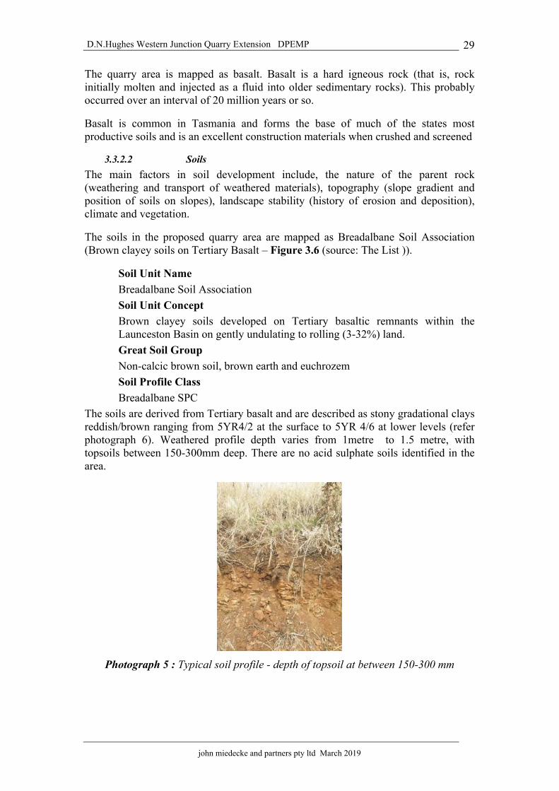
D.N.Hughes Western Junction Quarry Extension DPEMP
john miedecke and partners pty ltd March 2019
29
The quarry area is mapped as basalt. Basalt is a hard igneous rock (that is, rock initially molten and injected as a fluid into older sedimentary rocks). This probably occurred over an interval of 20 million years or so.
Basalt is common in Tasmania and forms the base of much of the states most productive soils and is an excellent construction materials when crushed and screened
3.3.2.2 Soils The main factors in soil development include, the nature of the parent rock (weathering and transport of weathered materials), topography (slope gradient and position of soils on slopes), landscape stability (history of erosion and deposition), climate and vegetation.
The soils in the proposed quarry area are mapped as Breadalbane Soil Association (Brown clayey soils on Tertiary Basalt – Figure 3.6 (source: The List )).
Soil Unit Name Breadalbane Soil Association Soil Unit Concept Brown clayey soils developed on Tertiary basaltic remnants within the Launceston Basin on gently undulating to rolling (3-32%) land. Great Soil Group Non-calcic brown soil, brown earth and euchrozem Soil Profile Class Breadalbane SPC
The soils are derived from Tertiary basalt and are described as stony gradational clays reddish/brown ranging from 5YR4/2 at the surface to 5YR 4/6 at lower levels (refer photograph 6). Weathered profile depth varies from 1metre to 1.5 metre, with topsoils between 150-300mm deep. There are no acid sulphate soils identified in the area.
Photograph 5 : Typical soil profile - depth of topsoil at between 150-300 mm

D.N.Hughes Western Junction Quarry Extension DPEMP
john miedecke and partners pty ltd March 2019
30
FIGURE 3.6: SOIL ASSOCIATIONS (Source- The List)
3.3.3 Land Capability
Figure 3.7 shows the land capability of the area.
FIGURE 3.7: LAND CAPABILITY (Source- The List)
The proposed quarry area is classified as Class 4. This is land well suited to grazing and limited occasional cropping using a very restricted range of crops.
To the east the land is classified as Class 5. Land with slight to moderate limitations
Relbia Soil Association
Breadalbane Soil Association

D.N.Hughes Western Junction Quarry Extension DPEMP
john miedecke and partners pty ltd March 2019
31
to pastoral use. This land is unsuitable for cropping, although some areas on easier slopes may be cultivated for pasture establishment or renewal. Some of this land is used for viticulture.
3.3.4 Surface and Groundwaters 3.3.4.1 Surface Waters
Briary Creek is the major water course that drains an extensive area that includes the general quarry area to the west and north of the airport. Figure 3.8 shows the catchment. The Creek flows to the east and joins Kelley’s Creek, Roses Rivulet and eventually the North Esk River.
FIGURE 3.8: SURFACE WATER CATCHMENTS (SOURCE; THE LIST)
The catchment area includes residences, industrial areas, areas of cropping, ploughed paddocks and grazing. The creek also received drainage form the Taswater sewerage ponds.
The creek is bounded by hawthorns, willows, brambles and blackberries in the quarry area. A large water supply pond has been constructed on the Creek between the existing quarry pits and drainage from workings areas is directed into the pond. Water quality is good with little or no evidence of significant sediment movement downstream (Table 3.2). The table shows that there is elevated E Coli bacteria in the stream, which indicate contamination from the Taswater sewerage ponds and/or other sources. The water quality makes it unsafe for human consumption and contact.
The proposed quarry extension is located on gentle slopes that drain to a central grassed depression. There are no well defined drainage lines or watercourses with the “drainage line” having a fully grass cover. Flows are ephemeral (seasonal flow) only

� ��� ��� ���� ��� �� � �� ������ ��� �� �� ����� ���� � ����� � ����� ���� ! �"���#$ %&��� ���� � ����� $ %&��� ���� ! �"���#' �� � ����� ' �� ! �"���#( �)����� %��� * ��+ ��� ��,- .���� )/ )%,0,� ��,
1234 ,��)� �, ��%� �)�� %�5
678 9:;< 98<8 98;2 =�3 8 9<>8 9:;? 9@ A: 9@B 9? A< 9@
CD EEFG HIJK LMNIOP8>:@:>:: 9Q:Q:? 9R
CD EEFG HIJK LMNIO66S< 9<R< 9:<R@ 9Q?R@ 9@8RR 9;>< 9<?
T IS6IUVW XUIY Z8 9:R? 9;?8 9<RQ 9R<: 9BR8 98R? A>?
Z FOJ X[WD HDW M\]̂ [S<:?R@>B:B@:>Q<??Q:RR;? A;;@@
T XU_DJDW MT̀aR>R<?
B A?@
KbcSd
RB<R?8R:<
e 9[FGDc IUR@@ SfR;B>R@@R?@R?@@R@R;@
] XE6IOJ IJ] FGDJ ESNf̂ g? g;g?g;g?
32B A?@
KDGhi UIVEIg? g;g?g;g?g;
'� ,,%� j�+k �� �� , l UEIOD [SNf̂ g@ 9@@R g@ 9@R g@ 9@@R g@ 9@R g@ 9@@R g@ 9@R@ 9@?@ 9@;Q
Z VJ SD XSSNf̂ g@ 9@@@R g@ 9@@R g@ 9@@@R g@ 9@@R g@ 9@@@R g@ 9@@R@ 9@@?@ 9@@@;
Zm UFSD XSSNf̂ g@ 9@@R g@ 9@R g@ 9@@R g@ 9@R g@ 9@@R g@ 9@R@ 9@?
Z F66IUSNf̂@ 9@@; g@ 9@R@ 9@@; g@ 9@R@ 9@@; g@ 9@RR
@ 9@@RQ
D̀ [n IG SNf̂@ 9@@; g@ 9@R@ 9@@; g@ 9@R@ 9@@; g@ 9@R@ 9R@ 9@RR
f IVJSNf̂ g@ 9@@R g@ 9@R g@ 9@@R g@ 9@R g@ 9@@R g@ 9@R
@ 9@@>Q
oD O[SNf̂@ 9@RR g@ 9@R@ 9@R; g@ 9@R g@ 9@@? g@ 9@R?
@ 9@@<
p IU[XUMSNf̂ g@ 9@@@R g@ 9@@@R g@ 9@@@R g@ 9@@@R g@ 9@@@R g@ 9@@@R
@ 9@@@B
q %� ��k �� �� , l UEIOD [SNf̂ g@ 9@@R g@ 9@R g@ 9@@R g@ 9@R g@ 9@@R g@ 9@R@ 9@?@ 9@;Q
Z VJ SD XSSNf̂ g@ 9@@@R g@ 9@@R g@ 9@@@R g@ 9@@R g@ 9@@@R g@ 9@@R@ 9@@?@ 9@@@;
Zm UFSD XSSNf̂ g@ 9@@R g@ 9@R g@ 9@@R g@ 9@R g@ 9@@R g@ 9@R@ 9@?
Z F66IUSNf̂@ 9@@Q g@ 9@R@ 9@@; g@ 9@R@ 9@@> g@ 9@RR
@ 9@@RQ
D̀ [n IG SNf̂@ 9@@> g@ 9@R@ 9@@> g@ 9@R@ 9@@> g@ 9@R@ 9R@ 9@RR
f IVJSNf̂ g@ 9@@R g@ 9@R@ 9@@R g@ 9@R g@ 9@@R g@ 9@R
@ 9@@>Q
oD O[SNf̂ g@ 9@@? g@ 9@R g@ 9@@? g@ 9@R g@ 9@@? g@ 9@R?
@ 9@@<
p IU[XUMSNf̂ g@ 9@@@R g@ 9@@@R g@ 9@@@R g@ 9@@@R g@ 9@@@R g@ 9@@@R
@ 9@@@B
]m VJ IJ rcm MED [VG 6VUVSIW IUEsD IGJ VOVG MEIJtu �+ ���+" %�+ re L[IIJ VO[IFs NXDJ IGD OIE
TABL
E 3.
2 W
ATE
R M
ON
ITO
RIN
G R
ESU
LTS

D.N.Hughes Western Junction Quarry Extension DPEMP
john miedecke and partners pty ltd March 2019
32
after heavy rainfall events and these eventually drain to the creek and the quarry water storage dam in Briary Creek via a culvert under the access road. Figure 3.9 shows the catchment on a LIDAR ( airborne radar image).
FIGURE 3.9:`SURFACE WATER CATCHMENTS LIDAR (Source-The List)
3.3.4.2 Groundwaters The quarry area is mapped as basalt. These rocks are generally jointed and fractured and therefore have a high permeability.
The experience with quarries in the area is that the groundwater level is below the quarry floors and while water ponds on the pit floors in rainfall events, it drains away in a short time.
Figure 3.10 shows the groundwater bores in the area. The closest is presumably a monitoring well on the Airport property to the South West and the standing water level was 10-20 metres below surface.
EPA have raised the issue of potential contamination of fire fighting foams (PFAS chemicals). This has been discussed with Airservices Australia and the EPA.
The main source of contamination is understood to be over 1.25km from the proposed new quarry, with groundwater flow directions away from the quarry area. There has

D.N.Hughes Western Junction Quarry Extension DPEMP
john miedecke and partners pty ltd March 2019
33
never been any groundwater flows in the existing pit. Therefore, the risk of contamination is regarded as low.
It is proposed that PFAS will be monitored in the nearest borehole (in conjunction with Airservices) and any groundwater inflows into the pit will be monitored for PFAS on a 3 yearly basis
FIGURE 3.10: GROUNDWATER BORES (SOURCE; WIST)
3.4 Biological Environment Overview – Flora and Fauna The mining lease area is mapped as Agricultural Land by LIST (see Figure 3.11) and no endangered species were identified in the area. Therefore, no specific flora and fauna surveys were commissioned. Bis undertake regular weed surveys and these are regularly treated.

D.N.Hughes Western Junction Quarry Extension DPEMP
john miedecke and partners pty ltd March 2019
34
FIGURE 3.11: VEGETATION (Source; The List)
3.5 Social Environment Overview 3.5.1 Socio-economic setting
The quarry is located in the Northern Midlands Council municipality.
Northern Midlands is one of the largest and most diverse municipalities in Tasmania. It covers an area of 5,130 km, extending from Liffey Bluff in the west to Mount St John in the east (150kms) and from Relbia in the north to Tooms Lake in the south (95kms). The landscape changes from mountainous country on its eastern and western boundaries to extensive grazing lands renowned for fine wool production; the rich agricultural river flats of the Esk, Lake and Macquarie Rivers historic towns and villages; and from small businesses to multi-million dollar enterprises.
Many of the towns and villages have distinctive heritage qualities, which make them attractive places to live.
The population of approximately 12,500 is expected to increase by 1,000 over the next five years as development continues to occur in and around the Launceston commuter towns of Longford, Perth and Evandale.
Situated on the Midlands Highway, 13 kms from Launceston, Breadalbane was named by Governor Macquarie after the Earl of Breadalbane, his wife's cousin. Earlier the district was known as 'Cocked Hat', 'The Springs' and 'Brumby's Plain'. The Breadalbane area was notorious in the early 19th century for sheep stealing. In the colonial days there were three inns at Breadalbane, The Albion, The Temperance Hotel, and The Woolpack Inn (today, only the Woolpack Inn still stands). Increased traffic on the roads into Launceston in the 1860's saw the introduction of a toll gate at Breadalbane. Road tolls were unpopular, and were eventually abolished in 1880.
Agricultural Land

D.N.Hughes Western Junction Quarry Extension DPEMP
john miedecke and partners pty ltd March 2019
35
Today, there is an important roundabout at Breadalbane at the entrance to the city of Launceston and Launceston Airport. The airport itself is now an important commercial and industrial centre with major expansion in the industrial area in recent years.
3.5.2 Heritage
There are no European heritage sites in the area of the quarry and the Tasmanian Heritage Council, National Estate and Parks and Wildlife data bases were searched for any sites of European heritage in the actual quarry area. None were identified.
The planning scheme lists the following buildings in Breadalbane.
20 RNE C ‘Rathmolyn’, Midlands Hwy 21 R ‘Woolpack Inn’, Hobart Road.
3.3.3 Aboriginal Heritage
No specific surveys were required by the EPA guidelines. The Aboriginal Relics Act 1975, provides legislative protection to Aboriginal heritage sites in Tasmania regardless of site type, condition, size or land tenure. Section 14(1) of the Act states that;
“Except as otherwise provided in this Act, no person shall, otherwise than in accordance with the terms of a permit granted by the Minister on the recommendation of the Director of National Parks and Wildlife:
• destroy, damage, deface, conceal or otherwise interfere with a relic;
• make a copy or replica of a carving or engraving that is a relic by rubbing, tracing,casting or other means that involves direct contact with the carving or engraving;
• remove a relic from the place where it is found or abandoned;
• sell or offer or expose for sale, exchange, or otherwise dispose of a relic or any otherobject that so nearly resembles a relic as to be likely to deceive or be capable ofbeing mistaken for a relic;
• take a relic, or permit a relic to be taken, out of this State; or
• cause an excavation to be made or any other work to be carried out on Crown landfor the purpose of searching for a relic.
lf a relic is suspected and/or identified during works then works must cease immediately and the Tasmanian Aboriginal Land and Sea Council and the Aboriginal Heritage Tasmania be contacted for advice before work can continue. If damage to an Aboriginal heritage site is unavoidable a permit under Section 14 of the Aboriginal Relics Act 1975 will be applied for by the quarry operator”.
The Unanticipated Discovery Plan will be followed during earthworks to meet the requirements under the Act if Aboriginal heritage were to be uncovered.
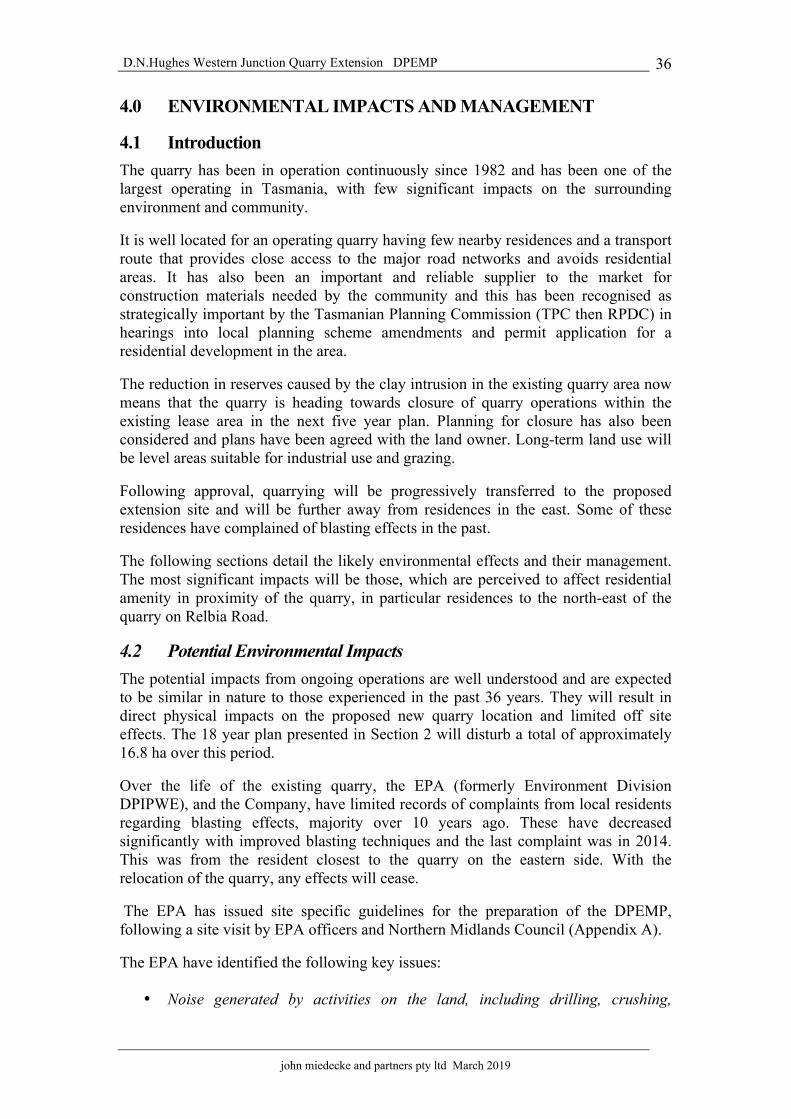
D.N.Hughes Western Junction Quarry Extension DPEMP
john miedecke and partners pty ltd March 2019
36
4.0 ENVIRONMENTAL IMPACTS AND MANAGEMENT
4.1 Introduction The quarry has been in operation continuously since 1982 and has been one of the largest operating in Tasmania, with few significant impacts on the surrounding environment and community.
It is well located for an operating quarry having few nearby residences and a transport route that provides close access to the major road networks and avoids residential areas. It has also been an important and reliable supplier to the market for construction materials needed by the community and this has been recognised as strategically important by the Tasmanian Planning Commission (TPC then RPDC) in hearings into local planning scheme amendments and permit application for a residential development in the area.
The reduction in reserves caused by the clay intrusion in the existing quarry area now means that the quarry is heading towards closure of quarry operations within the existing lease area in the next five year plan. Planning for closure has also been considered and plans have been agreed with the land owner. Long-term land use will be level areas suitable for industrial use and grazing.
Following approval, quarrying will be progressively transferred to the proposed extension site and will be further away from residences in the east. Some of these residences have complained of blasting effects in the past.
The following sections detail the likely environmental effects and their management. The most significant impacts will be those, which are perceived to affect residential amenity in proximity of the quarry, in particular residences to the north-east of the quarry on Relbia Road.
4.2 Potential Environmental Impacts The potential impacts from ongoing operations are well understood and are expected to be similar in nature to those experienced in the past 36 years. They will result in direct physical impacts on the proposed new quarry location and limited off site effects. The 18 year plan presented in Section 2 will disturb a total of approximately 16.8 ha over this period.
Over the life of the existing quarry, the EPA (formerly Environment Division DPIPWE), and the Company, have limited records of complaints from local residents regarding blasting effects, majority over 10 years ago. These have decreased significantly with improved blasting techniques and the last complaint was in 2014. This was from the resident closest to the quarry on the eastern side. With the relocation of the quarry, any effects will cease.
The EPA has issued site specific guidelines for the preparation of the DPEMP, following a site visit by EPA officers and Northern Midlands Council (Appendix A).
The EPA have identified the following key issues:
• Noise generated by activities on the land, including drilling, crushing,

D.N.Hughes Western Junction Quarry Extension DPEMP
john miedecke and partners pty ltd March 2019
37
screening and transportation to and from the land. • Blasting impacts;• Dust impacts; and• Stormwater management.
These are addressed in the following Sections, with other more minor environmental factors.
4.3 Noise from quarry operations 4.3.1 Noise studies
Noise Vibration Consultants (NVC) were engaged in 2017 to monitor noise from quarry operations under normal operating conditions and to provide advice on possible quarry options. Their final report is enclosed in Appendix D.
A number of noise surveys were conducted around the quarry and modeling was undertaken to determine the effects of extending quarry operations.
4.3.2 Existing Ambient Sound Levels
Ambient noise levels at three residences were measured on the 18h October 2017 . The measurement locations ( A - 578 Relbia Road, B - 55 Raeburn Rd and C - 81 Evandale Road). are shown in Figure 4.1, and the results summarised in Table 4.1.
FIGURE 4.1: QUARRY SITE AND MONITORING POSITIONS
A
B 975P/M
2045P/MC
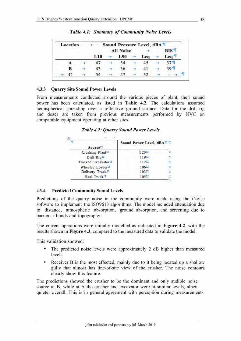
D.N.Hughes Western Junction Quarry Extension DPEMP
john miedecke and partners pty ltd March 2019
38
Table 4.1: Summary of Community Noise Levels
4.3.3 Quarry Site Sound Power Levels
From measurements conducted around the various pieces of plant, their sound power has been calculated, as listed in Table 4.2. The calculations assumed hemispherical spreading over a reflective ground surface. Data for the drill rig and dozer are taken from previous measurements performed by NVC on comparable equipment operating at other sites.
Table 4.2: Quarry Sound Power Levels
4.3.4 Predicted Community Sound Levels
Predictions of the quarry noise in the community were made using the iNoise software to implement the ISO9613 algorithms. The model included attenuation due to distance, atmospheric absorption, ground absorption, and screening due to barriers / bunds and topography.
The current operations were initially modelled as indicated in Figure 4.2, with the results shown in Figure 4.3, compared to the measured data to validate the model.
This validation showed: • The predicted noise levels were approximately 2 dB higher than measured
levels.• Receiver B is the most effected, mainly due to it being located up a shallow
gully that almost has line-of-site view of the crusher. The noise contoursclearly show this feature.
The predictions showed the crusher to be the dominant and only audible noise source at B, while at A the crusher and excavator were at similar levels, albeit quieter overall. This is in general agreement with perception during measurements

D.N.Hughes Western Junction Quarry Extension DPEMP
john miedecke and partners pty ltd March 2019
39
FIGURE 4.2: CURRENT OPERATIONS – ACOUSTIC MODEL INPUTS – GROUND CONTOURS
FIGURE 4.3: CURRENT OPERATIONS – PREDICTED NOISE CONTOURS.
The model is therefore considered valid. However, it is slightly overestimating the noise levels, and is thus considered to be conservative.
A
B
C
A
B
C

D.N.Hughes Western Junction Quarry Extension DPEMP
john miedecke and partners pty ltd March 2019
40
Four stages in the quarry expansion were modelled as they represent the least favourable outcome in noise stages for the life of the extension..
These stages were:
• Overburden and top soil removal:• Year 1 bench operations• Year 2 quarry operations• Year 5 quarry operations• Year 7 drill rig operations
Model input is shown in Figure 4.4.
FIGURE 4.4: YEAR 2 ACOUSTIC MODEL INPUT
In between each of these stages and beyond year 5, the equipment is either at a lower RL, or at greater distance from the residential receivers. Attenuation is therefore increased compared to the modeled cases (i.e. lower residential noise level). The mode l cases a re the least favourable over the life of the quarry.
In each stage the following aspects of operations are separately modelled: • Typical production: The haul truck, excavator, wheeled loaders and crusher
all operate continuously.• Drilling: The drill rig operates continuously in the most exposed location for
that stage.• Delivery trucks: Delivery trucks operate from the crusher to the weighbridge
(nominal edge of BIS land).The predicted community noise levels are then as listed in Table 4.3 with noise contour maps for the various stages shown in Figure 11 to Figure 15 in the report ( Appendix D)

D.N.Hughes Western Junction Quarry Extension DPEMP
john miedecke and partners pty ltd March 2019
41
Table 4.3: Predicted Community Noise Levels.
From the model results, the following is noted: • The crusher and drill rig are the clearly dominant noise sources at the
quarry. The drill rig, when establishing the first bench in areas A2 and A3,is the dominant quarrying noise source. Once it is operating on lowerbenches its received noise level drops by some 8 dB at location B, leavingthe crusher as the dominant noise source.
• The haul truck, excavator and wheeled loader are insignificant noise sourcesand may be ignored in assessing quarry noise emissions.
• Delivery trucks are likely to be just perceivable at locations B and C.• Locations B is the most effected location due to the almost line-of-site view
to the crusher.• To the east, the land falls away quite sharply to Relbia Road, then levels
out and/or rises a little. Receivers between Relbia Road and the quarryare therefore shielded by natural terrain from the quarry operations.
• At location A the quarry is likely to be inaudible.• There is minor screening of the drill rig from locations B and C during
year 5, due to the top soil bund just west of the drill rig.• From year 2 onwards, the excavator is screened by the quarry benches from
the receivers.• The Launceston Airport building experiences noise levels in the range 35 to
40 dBA.4.3.5 Noise Assessment Criteria
The quarry operates under license 3374 which has no specific noise criteria. The Quarry Code of Practice (QCP), is therefore referenced to determine appropriate criteria.
The QCP was revised and re issued in May 2017 and states at 7.2.2:
“ Noise from quarrying and associated activities, including equipment maintenance, when measured at any neighbouring sensitive use must not exceed the greater of: • the A-weighted 10 minute L90, excluding noise from the quarry, plus 5 dB(A), or• the following levels:
" 45 dB(A) from 0700 to 1900 hours (daytime)

D.N.Hughes Western Junction Quarry Extension DPEMP
john miedecke and partners pty ltd March 2019
42
" 40 dB(A) from 1900 to 2200 hours (evening), and " 35 dB(A) from 2200 to 0700 hours the following
day (night time) when measured as a 10 minute Leq. “
A permit from the EPA would typically qualify these levels by saying;
“ Where the combined level of noise from the activity and the normal ambient noise exceeds the noise levels stated above, this condition will not be considered to be breached unless the noise emissions from the activity are audible and exceed the ambient noise levels by at least 5 dB(A). “
Observing the noise limit for other quarries, Table 4.4, the daytime criteria of 45 dBA is tighter than the adjacent Stornoway quarry, but otherwise appears in line with other recent quarry developments.
The QCP criteria are therefore adopted for this assessment.
Table 4.4: Daytime Noise Limit, dBA, for Other Quarries
Cocked Hat Hill, Relbia 45 Stornoway Relbia 50 HBMI Leslie Vale 48
Hanson Flagstaff Gully 50 Hanson Underwood 45
Williams Quarry Tea Tree 47 Stornoway Mangalore 45
The attenuation code is often applied to separate uses with the potential to cause environmental harm from surrounding sensitive receivers, with the purpose of minimising the adverse effects of the quarry on the receiver. The attenuation distances from the code relevant to quarries is that for crushing operations, the attenuation distance is 750 m. Therefore, if it is observed, the nearest residences are outside this attenuation distance.
4.3.6 Noise Assessment
Quarry production is only in the daytime hours of the Quarry Code of Practice and hence only daytime noise levels were assessed. The current and predicted noise levels at the residences and their resulting assessment are summarised in Table 4.5.
The assessment shows that: • For normal operations (crushing hauling a n d carting) the quarry noise
emissions meet the quarry code of practice during all stages of theexpansion.
• When the drill rig is operating as well, noise levels at location B are abovethe criteria for the first 5 years. Beyond year 5 the noise emissions areacceptable.
It is noted that the drill rig is only for 1 or 2 days per month when the blast holes are drilled.

D.N.Hughes Western Junction Quarry Extension DPEMP
john miedecke and partners pty ltd March 2019
43
Table 4.5: Predicted Sound Pressure Levels at Nearby Residences and Assessment
4.3.7 Conclusions
The determined criteria are included in Table 4.5 and comparing the predicted least favourable noise case against the criteria shows the quarry development as a whole will achieve acceptable noise emissions. The exception is the blast-hole drilling rig,
4.3.8 Management
The major noise sources in the quarry are the mobile earthmoving equipment and the screening and crushing plants. These will all be located on the pit floor and below the natural surface. This will provide adequate screening to the nearest residences. All equipment will be maintained according to the equipment specifications.
The only noise source which NVC identified as requiring management, was the blasthole drill rig, where noise levels at location B are above the criteria for the first 5 years. Beyond year 5 they should comply.
When operations commence on the extension, a noise survey will be conducted within the first three months to confirm the noise predictions and assess any impacts. Any noise complaints will be recorded and acted on if received.
If required, the drilling rig will be fitted with a noise attenuation shroud or similar, to reduce emissions.
It is noted that the drill rig is only for 1 or 2 days per month when the blast holes are drilled and that the residence most likely to be affected is also located in the aircraft noise zones around the airport, and therefore subject to elevated noise levels.
The planning scheme gives protection to existing uses (such as the quarry) with its provisions for “attenuation areas” under the planning scheme provisions. Bis will cooperate with Council in determining appropriate buffer zones.
A complaints register will be maintained by Bis, which will record any noise complaints and the action taken in response. This will be monitored by the EPA.

D.N.Hughes Western Junction Quarry Extension DPEMP
john miedecke and partners pty ltd March 2019
44
4.3.9 Assessment of impact
Noise will be generated at the quarry throughout all stages of the proposed development by the drilling, blasting (see previous section), crushing, processing, loading and transport of rock products. Noise emissions from the current operation were monitored and future estimates of emissions were determined to be in compliance with the quarry noise criteria except for the blasthole rig when drilling.
Management measures to reduce emissions in the initial years will be implemented if required.
Adoption of improved technologies over the life of the proposal have the potential to further reduce noise emissions.
4.4 Noise and Vibration from Quarry Blasting 4.4.1 Introduction
Blasting is required to fracture the rock to allow its removal, after recoverable materials are removed by an excavator. This will continue to be required approximately once every month. Blasting will result in noise (called “airblast” or “air vibration” which typically may result in rattling windows) and ground vibration effects. There are established limits for both of these parameters which are internationally and nationally accepted.
Blasting at the quarry has been extensively monitored both by Bis (and contractors) to ensure that quarry operations meet the appropriate airblast (noise) and ground vibration standards.
Terrock Consulting Engineers, were engaged to advise on blast design and to ensure that quarry operations meet the appropriate airblast (noise) and ground vibration standards. They have completed a number of studies in the area, including for the Stornoway Raeburn quarry.
Their report is enclosed in Appendix E.
4.4.2 Blast Vibration Limits 4.4.2.1 Ground vibration
Ground vibration from blasting is barely noticed below 0.5 mm/s. The environmental ground vibration limits applied at the quarry are based on the Australian and New Zealand Environment Consultative Council (ANZECC) guidelines to minimise annoyance due to ground vibration from blasting and are set as a planning permit condition.
The environmental ground vibration limit is a peak vector particle velocity (PPV) of 5 mm/s at residences not owned or occupied by quarry personnel or at other sites with sensitive use. This limit may be exceeded on 5% of blasts in a 12 month period up to an absolute limit of 10 mm/s.
For the industrial area and airport runway to the south-west of the proposed extension, the limits can be higher as commercial structures are capable of withstanding higher forces. It is recommended that blast vibrations be kept under 10 mm/s for occupied commercial structures for all blasting by the quarry.

D.N.Hughes Western Junction Quarry Extension DPEMP
john miedecke and partners pty ltd March 2019
45
The prevention of damage to structures by blast vibration is a separate issue. 'Safe' levels for ground vibration limits to control damage to structures are recommended in Table J4.5(B) of Australian Standard 2187.2-2006, reproduced as Table 4.6.
Table 4.6 : Australian Standard 2187.2-2006 - Table J4.5(B) – Recommended Ground Vibration Limits for Control of Damage to Structures (see Note)
1.1.1.1.1 Category Type of blasting
operations
Peak component particle velocity (mm/s)
Other structures or architectural elements that include masonry, plaster and plasterboard in their construction
All blasting Frequency-dependent damage limit criteria Tables J4.4.2.1 and J4.4.4.1
Unoccupied structures of reinforced concrete or steel construction
All blasting 100 mm/s maximum unless agreement is reached with the owner that a higher limit may apply
Service structures, such as pipelines, powerlines and cables
All blasting Limit to be determined by structural design methodology
NOTE: Tables J4.5(A) and J4.5(B) do not cover high-rise buildings, buildings with long-span floors, specialist structures such as reservoirs, dams and hospitals, or buildings housing scientific equipment sensitive to vibration. These require special considerations, which may necessitate taking additional measurements on the structure itself, to detect any magnification of ground vibrations that might occur within the structure. Particular attention should be given to the response of suspended floors.
The proposed blasting practice will ensure that ground vibration levels do not exceed 5mm/s at any residential property, occupied industrial and airport buildings.
4.4.2.2 Air Vibration (air blast) Air vibration from blasting is barely noticed below 100 dBL. Air vibration limits applied at the quarry are based on guideline levels of the ANZECC guidelines to minimise annoyance due to blasting overpressure and are set as a planning permit condition. The air vibration limit at a residence or sensitive use site is a maximum of 115 dBL (peak), which may be exceeded on up to 5% of the total number of blasts over a twelve-month period, but should not exceed 120 dBL at any time.
This airblast limit is a human response limit intended to minimise the effect of airblast on people at sensitive sites, such as residences or schools and is not a limit to prevent possible damage.
Australian Standard 2187.2-2006 states:
'From Australian and overseas research, damage (even of a cosmetic nature) has not been found to occur at airblast levels below 133 dBL….. A limit of 133 dBL is recommended as a safe level that will prevent structural/architectural damage from airblast.'
The proposed blasting practice will ensure that airblast overpressure levels do not exceed 115dBL at any residential property, occupied industrial and airport buildings.

D.N.Hughes Western Junction Quarry Extension DPEMP
john miedecke and partners pty ltd March 2019
46
4.4.3 Determination of Ground Vibration Levels 4.4.4.1 Basis for blast vibration level evaluations
The vibration from a blast in the quarry is continuously monitored by Maxam (the blasting contractor) with the results being used in this assessment. Recently blasting that will conform with the typical blasting of the extension have been used for these predictions.
The blasting specifications used in the blast vibration analysis are shown in Table 4.7. Currently and for future blasting, the explosives used will be the Maxam watergel RIOFLEX explosives, as its characteristics are better suited to the rock encountered.
As the quarry progresses through the proposed expansion and working its way towards the airport in the later years of development, a reduced scale of blasting may be needed in order to keep levels under control but these changes will need to be reviewed and monitored as the quarry approaches the south western edge of the pit extension.
Table 4.7: Blast specifications used in analysis
Typical Blast Specifications Bench height (m): 14 Hole depth (m): 15 Hole angle (o): 10
Blasthole diameter (mm): 89 Blasthole spacing (m) 2.8 Blasthole burden (m): 2.5 Front Row Burden (m) 3.6 Stemming height (m): 3
Explosive RIOFLEX Charge mass per m (kg) 8.1 Charge mass per delay
(kg): 97
Powder factor (mg/m3): 1.012
4.4.4.2 Evaluation of maximum ground vibration levels Ground vibration varies with distance from the blast, charge mass per delay, type of explosive, geological conditions, and blasting specifications. For similar geological conditions and blasting specifications, ground vibration varies with distance and charge mass per delay, according to the Site Law formula:
V = [1]
where: V = ground vibration as peak particle velocity (PPV) (mm/s) D = distance from blast (m) W = charge mass per delay (kg) b = site exponent or drop off (attenuation) rate kg = site constant
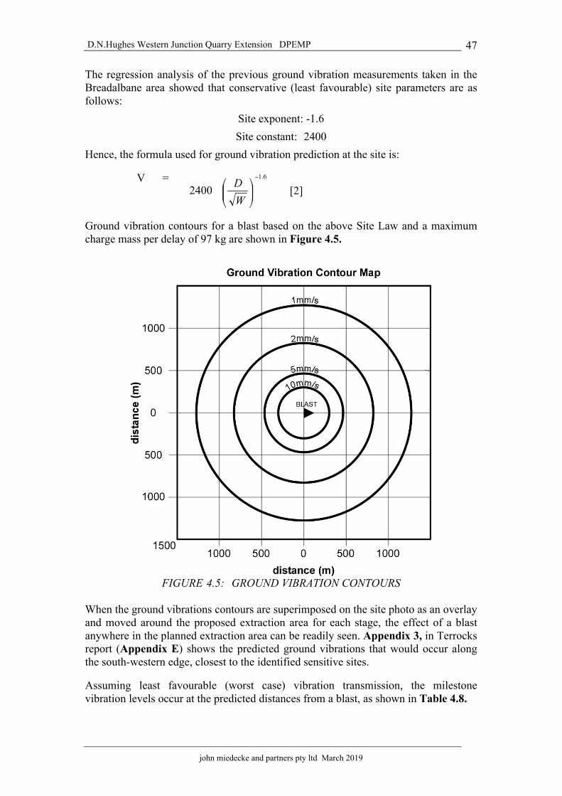
D.N.Hughes Western Junction Quarry Extension DPEMP
john miedecke and partners pty ltd March 2019
47
The regression analysis of the previous ground vibration measurements taken in the Breadalbane area showed that conservative (least favourable) site parameters are as follows:
Site exponent: -1.6 Site constant: 2400
Hence, the formula used for ground vibration prediction at the site is:
V = [2]
Ground vibration contours for a blast based on the above Site Law and a maximum charge mass per delay of 97 kg are shown in Figure 4.5.
FIGURE 4.5: GROUND VIBRATION CONTOURS
When the ground vibrations contours are superimposed on the site photo as an overlay and moved around the proposed extraction area for each stage, the effect of a blast anywhere in the planned extraction area can be readily seen. Appendix 3, in Terrocks report (Appendix E) shows the predicted ground vibrations that would occur along the south-western edge, closest to the identified sensitive sites.
Assuming least favourable (worst case) vibration transmission, the milestone vibration levels occur at the predicted distances from a blast, as shown in Table 4.8.

D.N.Hughes Western Junction Quarry Extension DPEMP
john miedecke and partners pty ltd March 2019
48
Table 4.8 :Estimated ground vibration levels
PPV
(mm/s) Distance(m)
10 303
5 467
2 828
1 1277
The maximum extent of the 10, 5, and 2 mm/s contours for blasting using 97 kg of explosives is shown in Appendix 3. These represent the highest ground vibration levels in the area surrounding the quarry for any blast over the life of the quarry.
The closest residential property to the quarry is located 800m to the north-west of the extension and at this distance the predicted ground vibrations level that would be generated by standard blasting practise would be 2.1 mm/s. This is below the limit of 5 mm/s and as this is the closest residential property, all residential properties beyond can be reasonably expected to be below this level.
Therefore, the peak ground vibration at any residence will be less that 5mm/s.
4.4.4.3 Prediction of maximum air blast levels The magnitude of airblast levels arriving at a point remote from the blast is a function of many parameters, including charge mass, confinement, burden, attenuation rate, shielding direction relative to the blast and meteorological conditions at the time of the blast. The attenuation rate for low frequency blast vibration has been found from experience to be a 9 dBL reduction with doubling of distance.
Analysis of blasting data from this and other quarries has permitted the relationship between maximum 120 dBL distance (the distance in front of the blast that the 120 dBL contours occurs), charge mass per delay and burden to be established.
The predictive model is: D120 =
[3]
D120 = Distance to the 120 dBL air blast level (m)
where: d = hole diameter (mm)
B = burden (mm)
m = charge mass (kg)
ka = site constant
For the empirical constant in quarries the following site constants are used:

D.N.Hughes Western Junction Quarry Extension DPEMP
john miedecke and partners pty ltd March 2019
49
In front of the face - ka = 250
Behind the face - ka = 160
For blasting in the proposed extension, from the analytical method, the 120 dBL distance for a 97 kg charge mass and a burden of 3 metres is a maximum of 688 metres in front of the blast. This equates to 115 dBL at 1070m in front of the blast face. For the airblast levels behind the face, the 115dBL distance is 540m.
Typical airblast levels radiate from a blast in an egg shape. This is due to the fact that the levels in front of a blast are 8-10 dBL higher than those behind a blast. The worst case airblast contours from standard blasting practise are shown in Figure 4.6.
FIGURE 4.6: WORST-CASE AIRBLAST CONTOURS FROM A STANDARD BLAST
4.4.4.4 Assessment of maximum air blast levels An assessment was made based on blast specifications for 89 mm diameter blastholes, a face height of 14 metres, and a charge mass of 97 kg for blasting in the pit extension with the face direction looking to be north-east, as shown in Appendix 4.
The distances to milestone airblast levels for future blasting practice and different orientations are shown in Table 4.9.
Table 4.9: Distances to milestone airblast levels for standard specification blasts
Pit Extension Blasting Air Vibration
Level (dBL)
Distance in front (m)
Distance at side/behind
(m) 120 688 347 115 1070 540 110 1529 732 105 2294 1118

D.N.Hughes Western Junction Quarry Extension DPEMP
john miedecke and partners pty ltd March 2019
50
The planned extraction sequence and resulting blast directions will enable air blast levels to be kept below the 115 dBL at any sensitive site for the remainder of the quarry’s operation.
4.4.4 Fly Rock
Efficient blasting practice results in broken rock being left in a pile next to the blasting face, but the possibility of flyrock and its effective control must always be considered.
Flyrock is controlled by having the explosive charge confined by sufficient stemming and burden. Care and attention to detail during all stages of face survey, blast design and loading will ensure that any rock throw will be contained within the Work Authority boundaries, and will present no danger to the public.
Flyrock distances for the proposed blast design have been calculated using the Terrock Flyrock Model, that is widely used for flyrock control in Australian quarries.
The maximum predicted rock throw in front of the face for the proposed specifications is 65 metres. To this distance Terrock recommend the application of two factors of safety for plant and equipment and personnel. For plant and equipment, a factor of safety of ‘2’ should be applied to the potential maximum throw of flyrock. A factor of ‘4’ should be applied for personnel and public. This clearance is applied in a 90o arc at 45o to the face of the blast.
In directions parallel to the face and behind the face, the possible flyrock mechanisms are cratering and rifling of the stemming (or gun barrelling). Providing the stemming height is greater than 20 hole diameters (1.8 metres), cratering will not occur. Rifling produces high trajectory flyrock with little horizontal projection.
For any direction behind the face or to the maximum flyrock throw will be 42 metres. The same recommended minimum clearance zones for plant, equipment, personnel and public are applied to each blast as shown in Figure 4.7.
Table 4.10 shows the breakdown of the maximum throw and the applicable clearance zones for that throw. As mentioned above, the factors of safety are ‘2’ and ‘4’ both in front and behind the face for all blasting. The maximum vertical throw is also shown.
Table 4.10: Distances of Flyrock and Clearance Zones
Horizontal Distance in front (m)
Distance at behind (m)
Vertical
Maximum Throw
65 42 65
Plant & Equipment
130 84
Personnel & Public
260 168

D.N.Hughes Western Junction Quarry Extension DPEMP
john miedecke and partners pty ltd March 2019
51
FIGURE 4.7: FLYROCK EXCLUSIONS ZONES
The adoption of the minimum exclusion zones in Figure 4.7 will prove conservative for most blasting. However, the determination of the exclusion zone is the responsibility of the quarry manager and shotfirer for each blast.
4.4.5 Management
Blasting in Tasmanian quarries is regulated by EPA Tasmania and Mineral Resources Tasmania through the Quarry Inspectorate. All quarries in Tasmania are required by law to record details of every blast in an official report book and these reports are available for official inspection. The report book includes a stocktaking section,

D.N.Hughes Western Junction Quarry Extension DPEMP
john miedecke and partners pty ltd March 2019
52
which can be checked against official records which explosives suppliers are required to keep. Quarry Managers and shotfirers are also required to hold statutory certificates and permits and are liable to have these suspended or cancelled if they do not obey the regulations.
Blasting must be carried out in accordance with the proposed blasting specifications and the applicable Explosives Use Regulations.
Compliance with vibration limits will be checked by the continuation of the monitoring regime conducted around the current working pit, modified as required to adequately monitor levels in the industrial area and airport terminal.
Compliance with vibration limits can be readily demonstrated by the adoption of a monitoring program to record the vibration levels from each blast.
All blasts will be monitored to ensure compliance with the blast vibration limits
Blasting will be only conducted between the hours of 10.30am and 3.30pm and effected residents in the area are notified by phone preceding each blast.
In addition to the residence at location B, the Launceston Airport control tower is notified and CASA were consulted in the Notice of Intent period and a copy of the fly rock template has been forwarded to CASA, as requested.
A complaints register will be maintained which will record any blasting complaints and the action taken in response. This will be monitored by the EPA.
In accordance with the planning scheme zoning, any proposals for residential (or sensitive uses) will be required to undertake site specific studies to demonstrate that these residential uses will not be affected by the quarry operations (see Section 3.2.2.6). These will be monitored by Bis and presumably Council.
4.4.6 Assessment of impact
Terrock have concluded that blasting can be carried out in the proposed quarry extension safely and in conformance with the Explosives Regulations 2012 of Tasmania and planning permit vibration limits, subject to compliance with the specifications and recommendations given in their report.
People within the range of perceptible ground vibration will experience both air and ground vibration from blasting for less than four seconds on about 12 occasions per year, depending on the blast size. Beyond the range of perceptible ground vibration, the air vibration may be perceptible for less than two seconds for each blast.
The peak ground vibration level will be less than 5 mm/s at residences in the surrounding area, as well as at the industrial areas and the airport terminal.
Blast vibration levels resulting at the Launceston Airport runway will be less than 10 mm/s and at the exclusion distance of 400m, the levels are predicted to be 6.40 mm/s when blasting is at its closest to the runway.
Airblast overpressure levels at the surrounding sensitive sites will be less than 115 dBL, as shown in Appendix 4 (Terrock Report Appendix E).

D.N.Hughes Western Junction Quarry Extension DPEMP
john miedecke and partners pty ltd March 2019
53
4.5 Dust (particulates) 4.5.1 Issues
Dust is more conventionally referred to as ‘particulates’ or ‘airborne particulates’. Airborne particulates are generated during quarrying mainly by mechanical disturbances (such as drilling, blasting, earthmoving and movement of road traffic on unsealed surfaces). In dry and windy conditions, particles can be lifted from open or disturbed areas, resulting in visible dust emissions. Most airborne particles that originate from these sources are larger than 10 µm (PM10) and are associated more with nuisance than with public health problems. The larger particles tend to settle back to the ground within a short distance (<300 m) from the source.
The size of a particle also determines its potential impact on human health. Larger particles are usually trapped in the nose and throat and swallowed. Smaller particles (less than (PM10) may reach the lungs and cause irritation there. Fine particles can be carried deep into the lungs and irritate the airways.
The Quarry Code recommends that generally, the emission of visible dust should be confined within the boundary of the premises, except in remote areas. Dust produced by the operation of the quarry or by transport, crushing and screening plant must be effectively controlled to the satisfaction of the EPA.
The degree of dust generation is a factor of the rock type when crushed (fines generated), abrasion resistance and the degree of fines generated in handling, in stockpiles and when transported. Some materials (silica) are well known for their ability to generate dust.
4.5.2 Quarry Emissions
The quarry operations will be similar to what has been happening in the past. They consist of drilling and blasting of rock, loading and haulage to processing facilities, crushing and screening, stockpiling, and loading for offsite transport.
All these phases of the operation will produce dust.
The generation of dust from quarrying and processing operations will depend on: • the frequency at which dust generating activities take place,• meteorological conditions, such as wind speed,• composition of dust, including particle size distribution (particle density and
moisture content), and• the condition of the source.
Wind directions for summer and Yearly averages for 9am and 3pm are shown in Figure 3.5. These indicate that at 9am winds are mostly from the north / north-west quadrant (40%) with also a south –south-east component at lower wind speeds. This applies also to summer. Wind velocities also tend to be low at 9am.
At 3pm, the winds are mostly from the N-NW directions (almost 60%, with the strongest winds from the north-west and north). In summer, winds are mainly from the same directions.
Therefore, when winds are strongest and in dry periods when dust generation is most
D.N.Hughes Western Junction Quarry Extension DPEMP
john miedecke and partners pty ltd March 2019
54
likely, wind directions are to the south -east and away from the closest residences and over agricultural land.
Dust deposition from the current or future operations at nearby residences is regarded as unlikely given the distance between the operation and nearby residences and the rapid fall-off in dust levels with distance. The access road is sealed from the boundary of the Lease and there are no residences adjoning the access road.
The main land uses surrounding the quarry area are agriculture, and ground preparation and crop harvesting. These will have the potential to contribute to airborne dust and affect ambient air quality.
Dust emissions from the above mentioned sources would exhibit a marked seasonal trend as ground cover and soil moisture content change (i.e. low soil moisture and reduced vegetation cover [i.e grass cover] in the summer months would contribute to higher levels of dust being generated).
4.5.3 Quarry Dust Management
The Permit conditions have various requirements. These include covering or dampening dust producing loads, controlling fugitive emissions (roads, stockpiles etc), and controls on dust emissions from plant. The crushing and screening plant is fitted with water sprays and dust extraction equipment. All truck loads which may generate dust will be covered or wetted down prior to transport. Roads and working areas will be watered with a water truck if required.
The effectiveness of current dust suppression will continue to be monitored by a complaint mechanism and specific dust monitoring will be conducted if complaints are received and can be verified and review of the causes will be examined and changes made to reduce further events of this nature.
A complaints register will be maintained by Bis which will record any dust complaints and the action taken in response. This will be monitored by the EPA.
4.5.4 Assessment of impact
Dust generated from the quarry in the past has not been a problem due to the separation distance and the prevailing wind directions. No residents have ever raised dust emissions as an issue of concern in over 35 years of operations.
Future operations are not expected to generate significant nuisance dust Other dust sources from agricultural activities are likely to be the major source.
4.6 Water Management 4.6.1. Issues
The risk to water quality from activities at the site is predominantly associated with surface water runoff, entrained particulate matter and possibly spilt fuels and oils. The existing quarry operations have been operating for over 30 years with no known water quality issues.
The existing water management in the current quarry operations is to direct surface drainage from active work areas, after passage through settling ponds, to the Briary

D.N.Hughes Western Junction Quarry Extension DPEMP
john miedecke and partners pty ltd March 2019
55
Creek supply pond (except the plant area). This pond overflows via a culvert under the haul road and flows continue down Briarly Creek. This pond also acts as a water supply for quarry and the crushing plant operations. Photograph 5 shows the pond.
Photograph 5: Water Supply pond in Briarly Creek
In the active quarry areas, surface drainage is contained in the pit floors where it gradually infiltrates the basalt fractures and joints and reports to the groundwater table. On occasions water is pumped from the Centre Pit to the pond, as required.
Settling ponds are in place for drainage from the Precoat Plant area, and a new settling pond is being constructed for the crushing /screening plant floor. This is to be located near the existing wash bay and has been sized to retain a 1 in 20 year, 12 hr duration rain event falling on the catchment. Appropriate runoff coefficients have been applied.
There are no known beneficial usage in receiving waters, which are ephemeral..
The new quarry operations will be on existing grazing pasture where the quarry will be progressively developed in areal extent and at depth.
There is no onsite storage of chemicals, other than a diesel storage tank, lubricants etc and these are stored undercover. There is vehicle and machinery maintenance and refueling on site in contained areas
4.6.2 Management 4.6.2.1 Quarry area
The measures to be adopted to prevent any sediment or pollution leaving the quarry and flowing offsite can be summarised as follows. These are essentially those that have been effective for the past quarry operations.

D.N.Hughes Western Junction Quarry Extension DPEMP
john miedecke and partners pty ltd March 2019
56
• The quarry perimeter will be graded such that all surface drainage is directedinto the pit itself and not off site, uncontrolled.
• Upslope water flows will be directed to a settling basin (1 or more to providestorm surge capacity and reduce flow rates).
• The pit floor will be graded to direct surface drainage to the settling basinsprior to discharge under the haul road to the Briarly Creek pond (this will alsoprovide storm surge capacity and reduce flow rates).
• All maintenance and refueling areas in the quarry will be bunded and anyspillage will be cleaned up. An oil spill kit will be maintained on site.Sediment Pond sizing
For sediment retention facilities a 1 in 20 year reoccurrence interval storm (12hr), will be used to determine pond sizes. Figure 4.8 shows the site water management plan. Table 4.11 shows indicative sediment pond sizing.
Table 4.11 Retention/Sediment Pond Sizes (Figure 4.8).
Pond No Catchment area (ha) (this will vary)
Required pond size m3
W1 5 750 W2 10 1500 W3 7.5 2200
# preliminary only. To be verified by site experience.
The ponds designed to act also as detention basins, will be provided with outlet pipes of 150mm diameter. Under normal conditions these will drain, and in storms fill to retain stormwater inflows before spilling.
4.6.2.2 Water Supplies Water for plant use will be sourced from the existing pond in Briarly Creek for quarry and plant use. Any external water sources can continue to be supplied from the Taswater supply.
No further surface water management measures are regarded as necessary.
4.6.2.3 Groundwater The quarry operating history is that the water table is below the existing quarry floor and therefore no groundwater is expected to be intersected in the quarry. The floor RL of the quarry extension is expected to be at RL 130, the existing quarry floor.
4.6.3 Assessment of Impact 4.6.3.1 Surface water
The ongoing quarry development has limited potential to affect water quality in receiving waters through hydrocarbon spills or discharge of turbid runoff to the watercourses. Consistent with existing drainage management measures, all runoff from disturbed areas will be diverted to onsite sedimentation dams and then the Briarly Creek pond.
Other measures to minimise any potential impact to the water quality include the storing and handling of hydrocarbons in accordance with relevant legislation and standards.

D.N.Hughes Western Junction Quarry Extension DPEMP
john miedecke and partners pty ltd March 2019
57
4.6.3.2 Groundwater There will be no deleterious impacts on groundwater, as the water table is well below the quarry floor. There may be some groundwater recharge from drainage from the pit floor.
4.7 Visual Effects The visibility of existing and planned future quarry activities has been a major part of the environmental management planning for the ongoing quarry operations and have been a major factor in the design of the quarry extension. To date the quarry has been developed on the edge of the ridgeline and behind a “bund” of topsoil and overburden.
The quarry extension will consist of the expansion of an original pit in a westerly direction. It will be an advancing face with the soils and overburden stripped and located to a stockpile area near the aerodrome ahead of the advancing face. This face will consist of 12m high vertical benches.
4.7.1 Landscape Setting
The existing quarry is located on the edge of the Tamar Valley Graben, on a flat topped low hill on Tertiary Basalt. All native vegetation has been removed in the area and the main land use is grazing and cropping, with the Launceston Airport to the south and west.
4.7.2 Visibility
The existing quarry operations are virtually not noticeable from the south, west and north, because of the sunken nature of the pits. The active pit is evident from the east and will be until closure in the next few years (see Photograph 6).
The visibility of the proposed quarry extension will be very limited, as it will progress in a north- westerly direction as a “pit”. The only open views will be from the east, where the topography shields the workings, which in addition are located behind the crusher and screening plant. Photograph 6 shows a view from Relbia Road, due East of the quarry. To the right is the Cromy Vineyard and the overburden bunds of the Stornoway Quarry.
Photograph 7 shows a view from Relbia Road, to the north of the quarry. To the right is the Cromy Vineyard and the overburden bunds of the Stornoway Quarry.
4.7.3 Management
The location for the quarry extension and the quarry designs, were selected to avoid environmental impacts, including minimising discernible visual change. The topography has presented opportunities for effectively screening the quarry operations, except for short durations when stockpiles near the airport are undergoing revegetation.
4.7.4 Assessment of impact
The quarry location and design will screen views to active working areas and prompt rehabilitation of bunds and stockpiles before they become visible and will maintain a natural-like appearance in the viewed landscape.

D.N.Hughes Western Junction Quarry Extension DPEMP
john miedecke and partners pty ltd March 2019
58
Other than a short duration when stockpiles are “fresh”, the quarry operations will be virtually not noticeable.
Photograph 6: Quarry Extension views from Relbia Road
Photograph 7: Quarry Extension views from Relbia Road to the North
Existing quarry operations
Clay overburden stockpile
Quarry extension area
BIS quarry stockpiles
Raeburn stockpiles
Cromy Vineyard

D.N.Hughes Western Junction Quarry Extension DPEMP
john miedecke and partners pty ltd March 2019
59
4.8 Roads and Traffic 4.8.1 Existing Conditions
4.8.1.1 Access Access to the site is via Richard Street, Western Junction, Photograph 8 shows the entrance. Richard Street is an existing access street servicing Industrial / Commercial frontage business with major heavy vehicle freight service depots in proximity to the quarry access. Traffic from the quarry travels 175m to a round-about on Evandale Road and most turn right toward Launceston and the Midland Highway.
Photograph 8 :Intersection of Access Road & Richards Street
The access road is maintained by Bis.
Traffic Engineer Terry Eaton carried out a traffic impact assessment and this report is included in Appendix B. He also considered a possible short term contract for bulk fill. This is no longer being considered.
4.8.1.2 Traffic Data A sample survey at the time of the site visit indicated an Average Daily Traffic (ADT) value of some 1,250 to 1,300 vehicles per day on Richard Street, with some 50% of traffic as heavy vehicles, i.e. trucks, semi-trailers and heavy combination vehicles. The high heavy vehicle percentage is seen as relative to the Transport Distribution land use activity fronting Richard Street.
Bis traffic is estimated at 12,000 vehicle loads annually will average some 45 truck loads per day. ADT value 66 truck trips (two-way movements).Site operations suggests an ADT at some 40 two-way light vehicle movements.

D.N.Hughes Western Junction Quarry Extension DPEMP
john miedecke and partners pty ltd March 2019
60
4.8.2 Proposal Impact
The cartage of the additional 140,000 tonnes of quarry material with similar average loading as present will require an additional 4,700 vehicle loads annually increasing the average daily loaded truck movements from the site to some 70, ADT value 100 truck trips (two-way movements)
4.8.3 Assessment
Eaton states;
“A traffic assessment for an increase in the annual quarry licence provisions for the BIS Industries quarry with access via the existing driveway to Richard Street, Western Junction, indicates compliance with Section E4.0 of the Northern Midlands Interim Planning Scheme”.
4.8.4 Management
No particular management measures have been identified.
4.8.5 Assessment of Impact
The overall assessment by Eaton is that the expected increase in the long term quarry operation will not significantly increase truck movements on Richard Street.
4.9 Wastes 4.9.1 Liquid
There will be no additional liquid wastes associated with ongoing quarry activities.
The existing septic tank is adequate and all used oils etc are stored and taken offsite for appropriate disposal. Oil spill kits are maintained on site.
4.9.2 Solid Wastes
The wastes generated at the site are those typically associated with machinery and processing plants. Wastes are managed in accordance with the following hierarchy of waste management:
• waste avoidance;• waste recycling;• waste re-use;• waste treatment; and• waste disposal.
All wastes will be disposed of in animal proof containers (in the quarry area) and the contents disposed of to a licensed waste disposal facility on a weekly basis.
4.10 Greenhouse Gases Greenhouse gases are generated by the following quarry activities;
• combustion of fuels by mobile plant, equipment and onsite vehicles• electrical power usage by processing plants• use of explosives for rock blasting;

D.N.Hughes Western Junction Quarry Extension DPEMP
john miedecke and partners pty ltd March 2019
61
• transport to marketsThe proposed quarry development is expected to possibly increase production by some 25%% in the next few years. In any case, if the quarry does not supply these materials, another supplier will. This will result in no net increase.
4.11 Dangerous Goods Materials on site, storage etc are discussed in Section 2.3.5.
The workshop, equipment etc are all provided with oil spill kits.
All these materials will be stored and transported in accordance with the Australian Code for the Transport of Dangerous Goods by Road and Rail, the Dangerous Goods Act 1998 and associated regulations.
4.12 Land Use The ongoing quarry operations will gradually replace the existing cropping and grazing in the property. Ultimately approximately 18.8 Ha will be disturbed over the 18 year quarry plan.
Because of the quarry design as a pit, with all quarry activities including material transport confined within the pit perimeters, there is little potential for alternative land use activities to be practiced until the quarry pit completes after year 18.
The pit walls will be progressively rehabilitated and after pit completion, the floor will be available for light industrial use.

D.N.Hughes Western Junction Quarry Extension DPEMP
john miedecke and partners pty ltd March 2019
62
5.0 ENVIRONMENTAL MANAGEMENT, MONITORING AND REVIEW 5.1 Environmental Management Bis have developed an environmental policy and this is attached in Appendix C. They are committed to achieving a situation in which they operate their support and logistics services whilst conserving resources, without causing pollution to the environment or harm to human health. In doing so, all their people are responsible for meeting or exceeding the environmental performance expectations of the business and its stakeholders.
Bis have entered a cooperative agreement with the Australian Government’s Department of Environment, Water, Heritage and the Arts. As a member of Greenhouse Challenge Plus they are meeting their commitments on the challenges presented by climate change.
They also have environmental management systems in place to measure and improve their CO2 emissions. These systems are aligned to ISO14001 and their customers’ licenses under the Environmental Protection Act. BIS consistently develop and implement site environmental management plans (SEMP) for all sites under their control.
As a large consumer of diesel fuel, BIS are taking a number of energy efficiency actions that will reduce emissions and improve their Greenhouse Performance Indicators.
Bis are also supporting and working closely with their largest on-site clients where they have Operational Control status under the Australian Government’s legislative programs. They provide key data to these clients to enable their reporting under two programs:
• Energy Efficiency Opportunities, a legislative initiative of the Department ofResources, Energy and Tourism.
• National Greenhouse and Energy Reporting System administered by theDepartment of Climate Change. This will lead to the pending AustralianEmissions Trading Scheme.
5.2 Environmental Monitoring and Review The program has been designed to meet the following objectives;
• Monitoring compliance with emission standards and other performancerequirements.
• Assessing the effectiveness of the performance requirements andenvironmental safeguards in achieving environmental quality objectives.
• Assessing the extent to which the predictions of environmental effects in theEMP have eventuated.
• The EMP is usually reviewed every five years.
The monitoring plan is shown in Table 5.1.
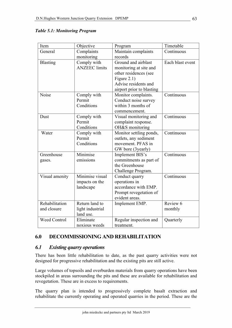
D.N.Hughes Western Junction Quarry Extension DPEMP
john miedecke and partners pty ltd March 2019
63
Table 5.1: Monitoring Program
Item Objective Program Timetable General Complaints
monitoring Maintain complaints records
Continuous
Blasting Comply with ANZEEC limits
Ground and airblast monitoring at site and other residences (see Figure 2.1) Advise residents and airport prior to blasting
Each blast event
Noise Comply with Permit Conditions
Monitor complaints. Conduct noise survey within 3 months of commencement.
Continuous
Dust Comply with Permit Conditions
Visual monitoring and complaint response. OH&S monitoring
Continuous
Water Comply with Permit Conditions
Monitor settling ponds, outlets, any sediment movement. PFAS in GW bore (3yearly)
Continuous
Greenhouse gases.
Minimise emissions
Implement BIS’s commitments as part of the Greenhouse Challenge Program.
Continuous
Visual amenity Minimise visual impacts on the landscape
Conduct quarry operations in accordance with EMP. Prompt revegetation of evident areas.
Continuous
Rehabilitation and closure
Return land to light industrial land use.
Implement EMP. Review 6 monthly
Weed Control Eliminate noxious weeds
Regular inspection and treatment.
Quarterly
6.0 DECOMMISSIONING AND REHABILITATION
6.1 Existing quarry operations There has been little rehabilitation to date, as the past quarry activities were not designed for progressive rehabilitation and the existing pits are still active.
Large volumes of topsoils and overburden materials from quarry operations have been stockpiled in areas surrounding the pits and these are available for rehabilitation and revegetation. These are in excess to requirements.
The quarry plan is intended to progressively complete basalt extraction and rehabilitate the currently operating and operated quarries in the period. These are the

D.N.Hughes Western Junction Quarry Extension DPEMP
john miedecke and partners pty ltd March 2019
64
western pit and the current operating (Eastern Pit). The pit which is the site of the crushing plan and stockpile area is currently not planned for closure as it will remain in operation.. The existing operations are conducted in accordance with the Environmental Management Plan – Operations 2010 (Miedecke, 2012).
The approved closure and rehabilitation plan for the existing quarry is shown in Figure 2.8.
The recommended rehabilitation plan is as follows (in accordance with the Quarry Code Of Practice):
• Salvage and recycling of redundant plant and equipment;• Profile and contour ripping;• Coverage with previously stockpiled materials from the stockpiles, and• Planting of tree seedling, seed and fertilizer application.
6.2 Quarry extension 6.2.1 Land form
The quarry extension area is in the form of a pit, with a relatively level base. The Quarry Plans discussed in Section 2.4 show an advancing face with final benches formed on both the north and south edges being established. These are approx 6m high by 4-5m wide to allow effective rehabilitation and these can be progressively revegetated (Figure 2.15). These can be a mix of pasture and/or native vegetation. Guidelines are set out below.
Rehabilitation will not be possible on the pit floor until closure. It is planned that the quarry floor would be left as a level compacted surface suitable for industrial and/or commercial use.
Figure 6.1 shows a conceptual closure plan for the Pit
6.2.2 Pasture revegetation
Once the topsoil has been re-spread it will need to be cultivated preferably with agricultural tines. Cultivation will occur in autumn, (two weeks following knock-down herbicide application) and immediately prior to sowing. Rocks will be present and seed application will be best completed using an agricultural spinner (also used for fertilizer application).
Basalt soils, particularly sub-soils are acidic and Ag-Lime application will be required at the rate of 10 tonne /ha. Ag-Lime is best applied by spreader trucks (e.g. Altrac Spreading).
Once the lime, seed and fertilizer have been applied, the surface will be harrowed.
Follow up weed control in the pasture will be required.
The proposed pasture species to cope with freer draining basalt topsoil and subsoils mix is as follows:
• Cover Crop of Cereal Rye (ryecorn) 40 kg/ha

JOHN MIEDECKE AND PARTNERS PTY LTD
Bis Western Junction Quarry Extension
F I G 6 . 1
Quarry Conceptual Closure Plan
W1
Quarry Floor - levelled and com-pacted as hardstand ( industrial
use)
Quarry wall benches shallowheights and depth.
RehabilitatedFigure 2.15
Quarry wall benches shallowheights and depth.
RehabilitatedFigure 2.15
Pit drainage directed to settlingpond and the supply pond
W2

D.N.Hughes Western Junction Quarry Extension DPEMP
john miedecke and partners pty ltd March 2019
65
• Ryegrass var Victorian 12 kg/ha• Ryegrass var Tama 08 kg/ha• Cocksfoot var Porto 05 kg/ha• White Clover var Huia 03 kg/ha• Sub-Clover var Trikkala 02 kg/ha
The recommended fertilizer is 14:16:11 at 500 kg/ha initially. The fertilizer should be applied by tractor and spinner.
Follow-up maintenance lime and fertilizer requirements should be based on future soil analysis.
6.2.3 Tree and Grass Species suitable for planting
The following species are able to cope with the conditions created following quarry development and final landform creation and will establish a self-sustaining stable community that will encourage a succession towards pre-disturbance vegetation.
The method of establishment will be by direct planting of native seedlings.
The recommended seedling species is from the list below:
• Acacia dealbata Seedling• Acacia mearnsii Seedling• Allocasuarina verticillata Seedling• Bursaria spinosa Seedling• Dodonea viscosa Seedling• Eucalyptus amygdalina Seedling• Eucalyptus globulus Seedling• Eucalyptus viminalis Seedling• Lomanadra longifolia Plugs• Poa labillardierei Plugs
All seedlings will be guarded, staked and fertilised when planted.
If browsing by animals is a problem, tree guards should be utilised with all seedlings while animal exclusion fencing can be utilised where it can be practically constructed.
6.2.4 Fertiliser
Fertiliser to be applied are a N:P:K fertiliser mix of 8:4:10 at 300 kg/ha. Based on annual monitoring inspections, maintenance fertilizer application may be required.
All grass plugs will be accompanied with 5 grams of Osmocote and seedlings should be planted with a 20 g Agriform fertiliser tablet or equivalent.
6.2.5 Maintenance
Periodic inspection and maintenance will be required. It is recommended that this be yearly.

D.N.Hughes Western Junction Quarry Extension DPEMP
john miedecke and partners pty ltd March 2019
66
6.2.6 Weed control
Bis has contracted Woodlands Corporation (Aust) Pty Ltd to control weeds on the Lease. Quarterly site inspections are made (including pathogens). Gorse, blackberries, thistles, flatweeds and rice grass occur on the lease and are being treated.
Vehicles and machinery are washed according to the weed and hygiene guidelines when transferring to and from susceptible or risky sites (Appendix E).
7.0 COMMITMENTS
The quarry will be operated in compliance with this DPEMP, the Quarry Code of Practice, Tasmanian State Policies and legislative and regulatory requirements.
It will also be operated in accordance with the planning and environmental conditions of the land use permit which will be issued by the Northern Midlands Council and the EPA. The Mining Lease will also have conditions determined by MRT.
The specific commitments associated with the potential impacts and their management measures are summarised in Table 6.1.
8.0 CONCLUSIONS
This development proposal and environmental management plan has been prepared to support a development application for the operation of the quarry (already permitted) at production rates of up to 320,000 m3 per year..
The pit will provide construction materials essential for the local community and the short term supply of bulk fill for the nearby highway upgrade.
It will continue to operate to the States social and economic benefit without any significant adverse environmental effects.
The potential impacts from the ongoing operations are well understood and will be similar in nature to those experienced previously over the past 36 years. They will result in direct physical impacts on the proposed location and limited off site effects.
The DPEMP has identified and assessed the potential impacts associated with the operations, in accordance with the DPEMP guidelines provided by EPA. It also demonstrates that appropriate operational and management measures have been identified and proposed to mitigate the potential impacts and to ensure minimal risk to the environment and human health.
The DPEMP demonstrates that the proposed activity will be compliant with Tasmanian Policies, Legislation and Regulations, and provides a monitoring program which will ensure compliance with standards and regulations.

Table 6.1: SUMMARY OF COMMITMENTS
Potential Impacts
Management measure commitments Timeframe
1 Residential amenity
Maintain a complaints register to record all complaints from the public.
As received.
2 Blasting Noise and Vibration
Advise Airport and residents within a 1km radius, (or as agreed) 24 hours in advance Monitor blasting to ensure compliance with standards.
Every blast (1mths approx).
3 Noise Emissions – onsite
Maintain attenuation distances to neighbours. Monitor noise emissions after operations commence. Noise attenuation on drill rig if needed.
Ongoing. Ongoing.
Ongoing..
4 Noise Emissions – offsite
Hours of operations to permit conditions No transportation on Sundays or gazetted public holidays. Transport road trucks maintained in good condition.
Continuous.
5 Water Management
Monitor and maintain settling basins and improve as necessary. Direct all runoff to Briarly Creek storage pond. Monitor groundwater inflows and well for PFAS
Continuous.
3yearly
6 Air Emissions onsite
Operate water sprays on crushing equipment Minimise surface disturbance. Progressive rehabilitation of disturbed areas Watering of internal roads. Maintain Quarry roads routinely.
As needed
Ongoing. Ongoing. As needed.
7 Air Emissions offsite
Transport trucks will be tarpaulin covered if required.
As needed. Ongoing.
8 Attenuation zone
Cooperate with Council to monitor a suitable attenuation zone.
As required.
9 Visual Management
Revegetate overburden and topsoil stockpiles.
Ongoing.
10 Weeds Yearly weed surveys and appropriate control. Washdown of equipment if from weed infected areas.
Ongoing.
11 Revegetation Strip and stockpile topsoil and overburden as per the guidelines. Revegetate quarry walls progressively.
Ongoing.

D.N.Hughes Western Junction Quarry Extension DPEMP
john miedecke and partners pty ltd March 2019
67
REFERENCES
Anon. 2008. Basalt at Breadalbane. MRT, 2008
EPA ,2017. Quarry Code of Practice, 3rd Edition,. EPA Tasmania, May 2017 http://epa.tas.gov.au/Documents/Quarry_Code_of_Practice.pdf
Miedecke, 2012. Environmental Management Plan – Operations 2010 (John Miedecke and Partners Pty Ltd, 2012)