wes marshall, p.e. university of connecticut february 2007 ce 276 site design chapter 3 –slope...
Post on 21-Dec-2015
228 views
TRANSCRIPT

Wes Marshall, P.E. University of ConnecticutFebruary 2007
CE 276Site Design
Chapter 3 –Slope Formula Application

What did we talk about last week?
Plotting Contours Interpolation
Mathematical Equations Graphical Method Cross-Section Method
Slopes & Calculating Slopes Slope Analysis Plan

Calculating Slope
S = DE/L = Rise / Run S = Slope (or gradient) DE = Difference in elevation between the end
points of a line L = Horizontal distance
Ris
e
Run

Other Ways to Express Slope
Slope is often described as a ratio such as 2:1
This equates to 2 units of horizontal distance for every 1 units of vertical elevation
Slope can also be shown in degrees, minutes, and seconds

Chapter 3Slope Formula Application

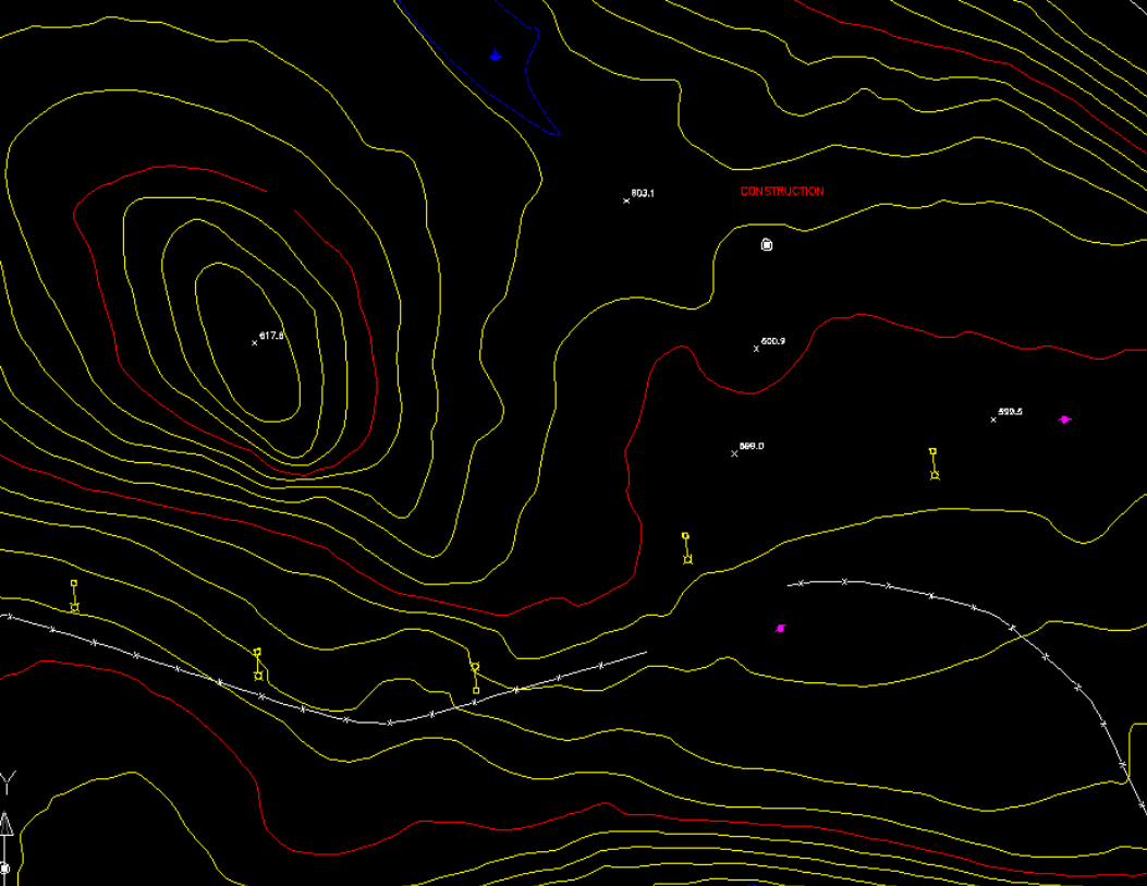
Slope Analysis
A slope analysis is used to depict the steepness of the terrain It should be used in conjunction with other
information (i.e. wetlands, vegetation, soils, etc.) to establish site constraints
Helps determine the best areas for locating buildings, roads, parking lots, and other uses on a particular site

Slope Analysis
Requires the following information:
Horizontal ScaleContour IntervalPercent Slope Categories


Slope Analysis
Being able to quickly & legibly create a slope analysis plan by hand is an important skill that can be used during design charrettes & client/public participation meetings when using a computer is not practical

Slope Analysis
Grading

Grading
Objectives of grading:
To change the form of the natural landscape to serve a particular use
To slope the surface in order to ensure proper drainage of storm water

Computers in Grading
Useful tool in topography analysis We already discussed the Slope Analysis
Plan, but there are other applications such as:Elevation PlansAspect (slope orientation) Plans3-D ViewsCross-SectionsCut & Fill Volumes

Computers in Grading
Contour Plan of Mount St. Helens 20 m contour lines
and 100 m index lines.

Computers in Grading
Slope Analysis Plan

Computers in Grading
DEM classified into 200 m classes
Digital elevation data can be used to derive many different types of analyses including:
Contours Slope Aspect surface hydrology watershed boundaries

Computers in Grading
Aspect Plan Indicates the
direction a slope faces (derived from the DEM)

Computers in Grading
3-D Model of Slope Analysis

Grading Around Buildings
Storm water should be directed away from buildings in order to: Avoid leakage into interior spaces Avoid saturating the soils (which reduces
the bearing capacity of the soil) Avoid moisture on the buildings
Drainage away from a building is often called positive drainage

Grading Around Buildings
Given: Spot Elevations
on building corners
Slope away from building (i.e. 3%)
Find: Contours
Building
Path/Road Layout & Grading
The design of a road often may not exceed a maximum gradient This may be due to:
ADA accessibility constraintsZoning codesRoad guidelines, or Commonsense

Example
Design a path from Point A to the Dock with a maximum slope of 4%

Example
S = DE L
0.04 = 1 L
L = 25 feet d

Example
Draw an arc of radius = 25’ at the proper scale from Point A
Mark intersections with next contour
Anything within shaded area is longer than 25’ & thus steeper than 4%

Example
Continue strategy on a contour-by-contour basis until reaching dock
Path should depend upon overall design intent, views, soils, etc.

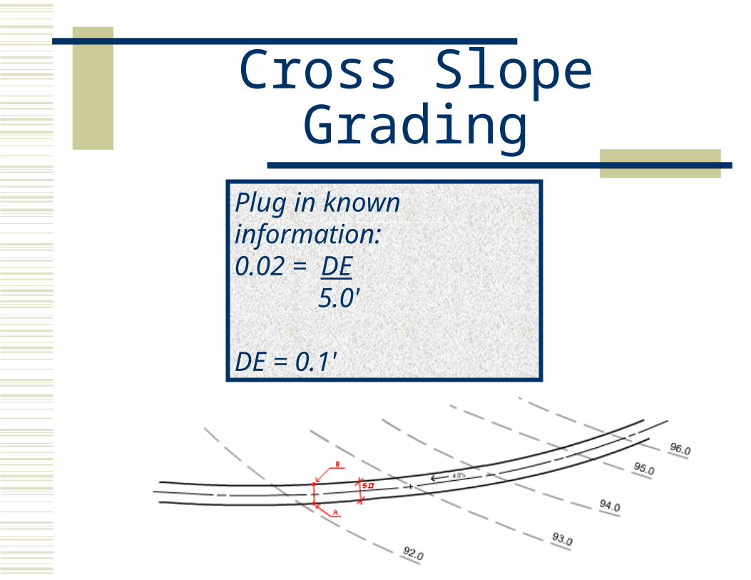
Cross Slope Grading
Cross slopes Prevents ponding of surface water Required on paths, driveways,
roads and other flat areas Also done on roads & paths
Sheds water to gutters or into the grass in order to keep the higher central surface from becoming inundated with water
Typically 1% to 2%

Cross Slope Grading
Step 1 Find the difference in elevation from
one side of the path to the other For this example, use a slope of 2%

Cross Slope Grading
Slope(S) = Difference in Elevation(DE) Horizontal Distance(L)
Cross Slope Grading
Plug in known information:0.02 = DE 5.0'
DE = 0.1'

Cross Slope Grading
S = 4%
B C
Step 2 Find the distance along the path necessary
to reach the point at the same elevation ofthe original contour

Cross Slope Grading
Distance from
pt. B to pt. C.
S = 4%
B C
the distance along the path necessary to reach the point at the same elevation as the original 92.0 contour
=

Cross Slope Grading
S = 4%
B CL = 2.5’
Plug in known information:0.04 = 0.1 L
L = 2.5

Cross Slope Grading
Combine steps to simplify the equation Can calculate a number of perpendicular
offsets quickly and efficiently
S = 4%
B CL = 2.5’

Cross Slope Grading
Perpendicular offset = location of the initial elevation on the other side of the path (or parking lot, road, terrace, etc.) Used whenever there are two slopes involved
rather than just one
S = 4%
B CL = 2.5’

Cross Slope Grading
S = 4%
B CL = 2.5’
DE = L S
DE = (Path Width)(Cross Slope)S = Longitudinal SlopeL = Perpendicular Offset

Cross Slope Grading
Step 3 Connect the points with the same elevation
This is the beginning of your proposed contour

Cross Slope Grading
Step 4 Connect either end of the diagonal line with the
existing contour line Make a smooth transition and place heavy tabs or
dots at the point at which they connect Continue this process for the rest of the contours

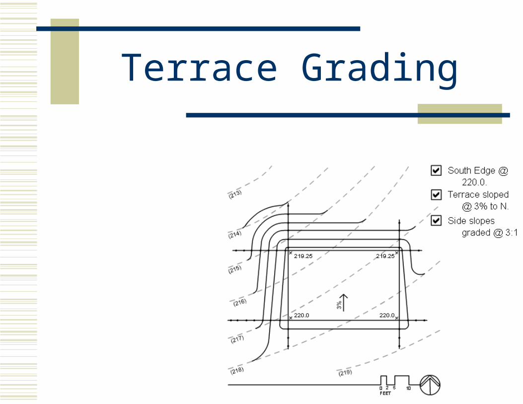
Terrace Grading
Another common grading problem Required on most hillside environments 3 Types
On Fill
In Cut
Partially on fill & partially in cut

Terrace Grading
Terrace measuring
25’ by 40’ South edge at
elevation 220.0’ Slope downward at
3% toward the north for drainage

Terrace Grading
Side slopes will be graded at a ratio of 3:1
This equates to 1 foot drop for every 3 feet of horizontal distance

Terrace Grading
One reason for a relatively steep is to return to the existing grade in the shortest distance possible
Why? This reduces the
area of disturbance caused by grading
Can reduce cost

Terrace Grading
Make a checklist of the criteria looking at the problem description:
South edge @ 220.0’
Terrace sloped @ 3% to North
Side slopes graded @ 3:1
Terrace Grading
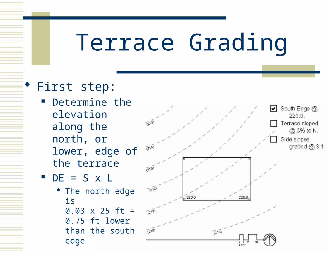
First step: Determine the
elevation along the north, or lower, edge of the terrace
DE = S x L The north edge is
0.03 x 25 ft = 0.75 ft lower than the south edge

Terrace Grading
220.0 - 0.75 = 219.25’
Thus, the spot elevations along north side of terrace are 219.25’

Terrace Grading
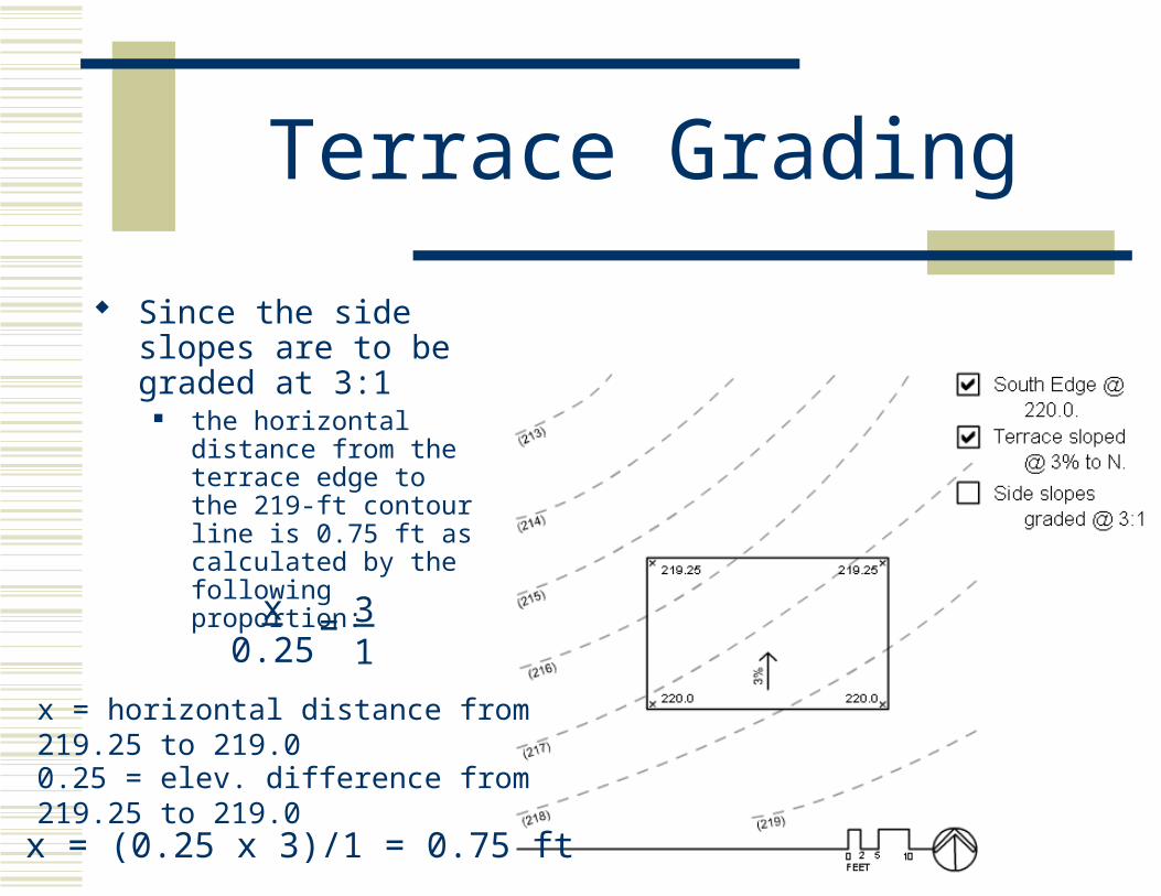
Next Step: Determine the
distance from the north edge of the terrace to the 219-ft contour line
Terrace Grading
Since the side slopes are to be graded at 3:1
the horizontal distance from the terrace edge to the 219-ft contour line is 0.75 ft as calculated by the following proportion:
x = horizontal distance from 219.25 to 219.0
0.25 = elev. difference from 219.25 to 219.0
31
=
x = (0.25 x 3)/1 = 0.75 ft
x0.25

Terrace Grading
This distance is marked off along lines drawn perpendicular to the terrace at the northeast and northwest corners

Terrace Grading
From the point of the 219 spot elevation:
The whole number spot elevations (i.e. 218, 217, 216, etc.) can be located by progressing along the line in 3-ft increments
For every 3 ft of horizontal distance, there is a 1-ft vertical drop
These points are used for the construction of the proposed contour lines.
Terrace Grading
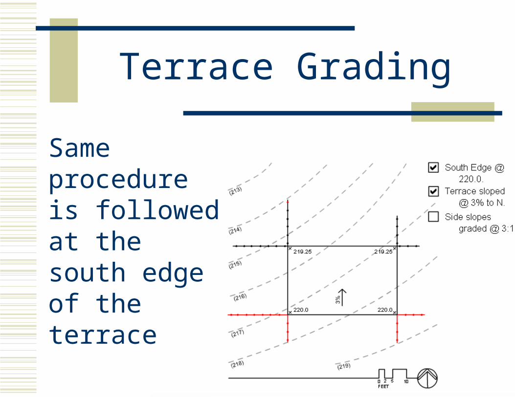
Same procedure is followed at the south edge of the terrace

Terrace Grading
Lines are drawn perpendicular to the terrace at the southeast and southwest corners

Terrace Grading
Since the elevation of the south edge is already at the whole number, 220…
The remaining whole number spot elevations can be located by progressing out from the edge in 3-ft increments

Terrace Grading
Begin with the 219’ contour line
Draw straight lines through the 219-ft spot elevations until the lines of adjacent sides intersect
The proposed 219-ft contour line is a closed contour since it never intersects with the 219-ft contour line already existing on the site

Terrace Grading

Terrace Grading
Proceed with the proposed 218’ contour line following the same technique:
The new 218’ contour line intersects the existing 218’ contour line at two points

Terrace Grading

Terrace Grading
Continue successively lower contour lines (217, 216, 215, etc.) until the point is reached where existing contours are no longer disturbed

Terrace Grading
Terrace Grading
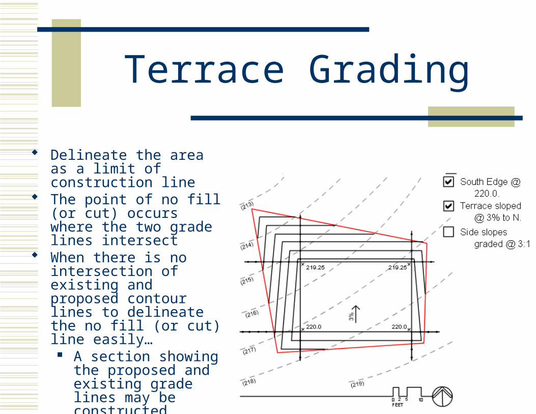
Delineate the area as a limit of construction line
The point of no fill (or cut) occurs where the two grade lines intersect
When there is no intersection of existing and proposed contour lines to delineate the no fill (or cut) line easily…
A section showing the proposed and existing grade lines may be constructed

Terrace Grading
Shaping the side slopes
What is shown is difficult to construct and maintain
It usually does not blend well with the surrounding landscape
Thus, the contours are given a smoother and more rounded appearance
Terrace Grading

Road Grading
TerminologyCrown = Difference in elevation
between the edge and the centerline of a roadway
Purpose: Allows water to drain from centerVisually separate opposing lanes of traffic

Crowns
Crowns are typically achieved by having the center of the road or path higher than the two edges

Crowns
Parabolic
Tangential
Reverse(infrequently used)
Section Plan
Crowns
Crowns can be characterized by:
Height
Ratio
Percentage
Road Grading
Terminology Curb = Vertical separation at the
edge of a roadway
Purpose: To direct & restrict storm runoff To provide vertical separation and safety for
pedestrians, bicyclists, etc.

Barrier Curb
Curbs
Beveled
Rounded
MountableNon-mountable

Road Grading
Terminology Swale = Constructed or natural drainage
channel with a vegetated surface
Gutter = Paved swale
Purpose: To intercept, direct, and control
storm water runoff

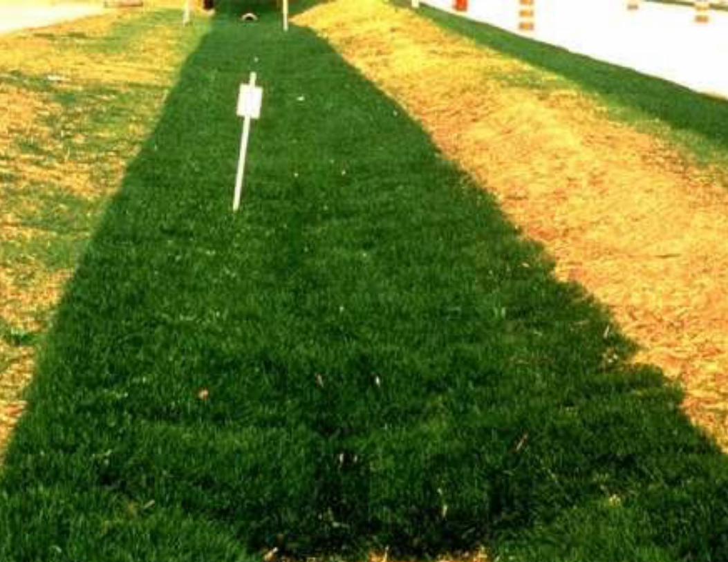
Swales
Swales are often found along roads for drainage
Swales are most often characterized by their depth

Swales
Vegetated Parabolic Swale
Paved Gutter
Combinationcurb & gutter

Swales
All 3 swales shown below have 3% grade & 15’ width
6” Deep
12” Deep
18” Deep

Swales
Swales are designed to convey water as part of an OPEN storm water system They are not meant to be continuously wet
Typically have parabolic cross-section
Typically lined with grass


Tricks to Drawing Contour Lines
Turn the plan so that you are looking in the downhill direction If drawn correctly, the contour lines should
look like a cross section with an exaggerated vertical scaleA swale should look like a valleyA crown should look like a ridgeThe shoulder should slope away from the road

Road Grading
Road grading with swales & curbs can be a little tricky
This figure depicts the plan & section for all 3 components (road, swale, curb) together
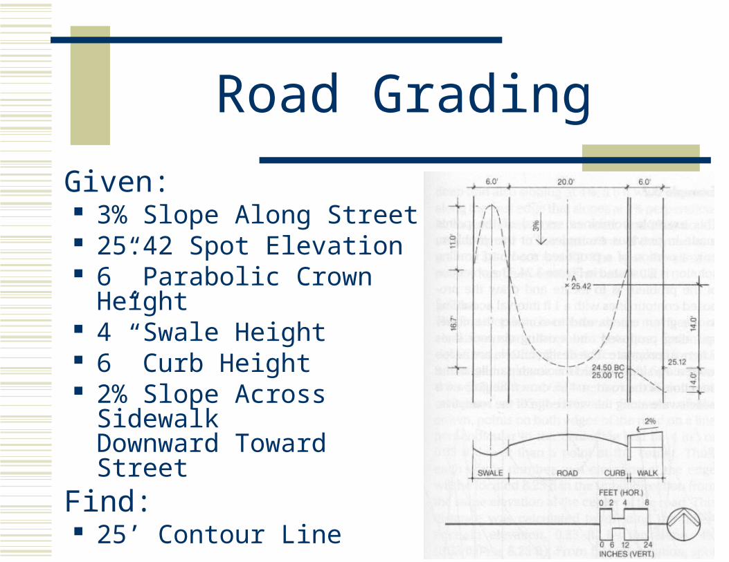
Road Grading
Given: 3% Slope Along Street 25.42 Spot Elevation 6” Parabolic Crown
Height 4” Swale Height 6” Curb Height 2% Slope Across Sidewalk
Downward Toward StreetFind: 25’ Contour Line

Road Grading