welds errors
TRANSCRIPT
7/31/2019 Welds Errors
http://slidepdf.com/reader/full/welds-errors 1/8
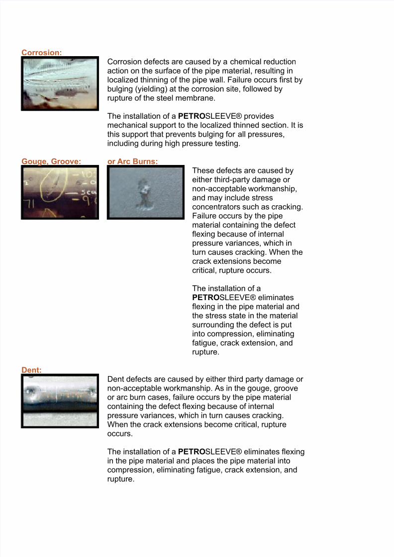
Corrosion:Corrosion defects are caused by a chemical reductionaction on the surface of the pipe material, resulting inlocalized thinning of the pipe wall. Failure occurs first bybulging (yielding) at the corrosion site, followed by
rupture of the steel membrane.
The installation of a PETROSLEEVE® providesmechanical support to the localized thinned section. It isthis support that prevents bulging for all pressures,including during high pressure testing.
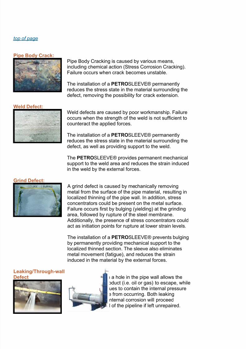
Gouge, Groove: or Arc Burns:These defects are caused byeither third-party damage or non-acceptable workmanship,
and may include stressconcentrators such as cracking.Failure occurs by the pipematerial containing the defectflexing because of internalpressure variances, which inturn causes cracking. When thecrack extensions becomecritical, rupture occurs.
The installation of aPETROSLEEVE® eliminatesflexing in the pipe material andthe stress state in the materialsurrounding the defect is putinto compression, eliminatingfatigue, crack extension, andrupture.
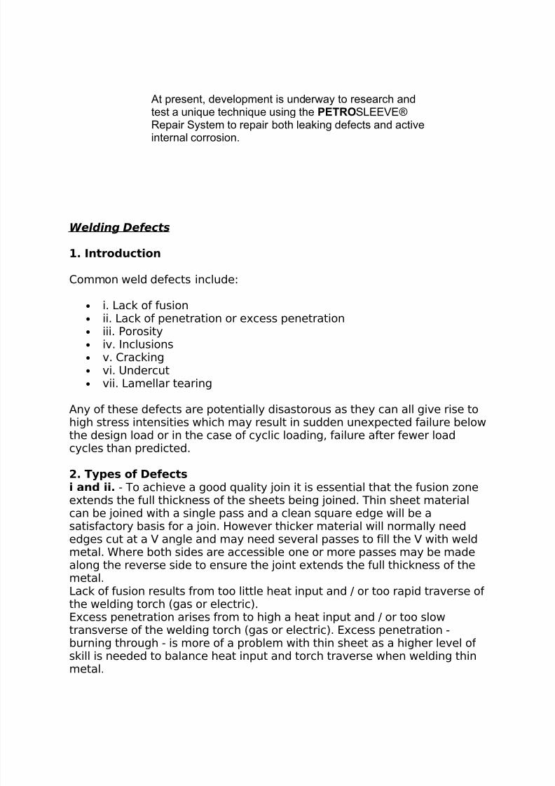
Dent:Dent defects are caused by either third party damage or
non-acceptable workmanship. As in the gouge, grooveor arc burn cases, failure occurs by the pipe materialcontaining the defect flexing because of internalpressure variances, which in turn causes cracking.When the crack extensions become critical, ruptureoccurs.
The installation of a PETROSLEEVE® eliminates flexingin the pipe material and places the pipe material intocompression, eliminating fatigue, crack extension, andrupture.
7/31/2019 Welds Errors
http://slidepdf.com/reader/full/welds-errors 2/8
top of page
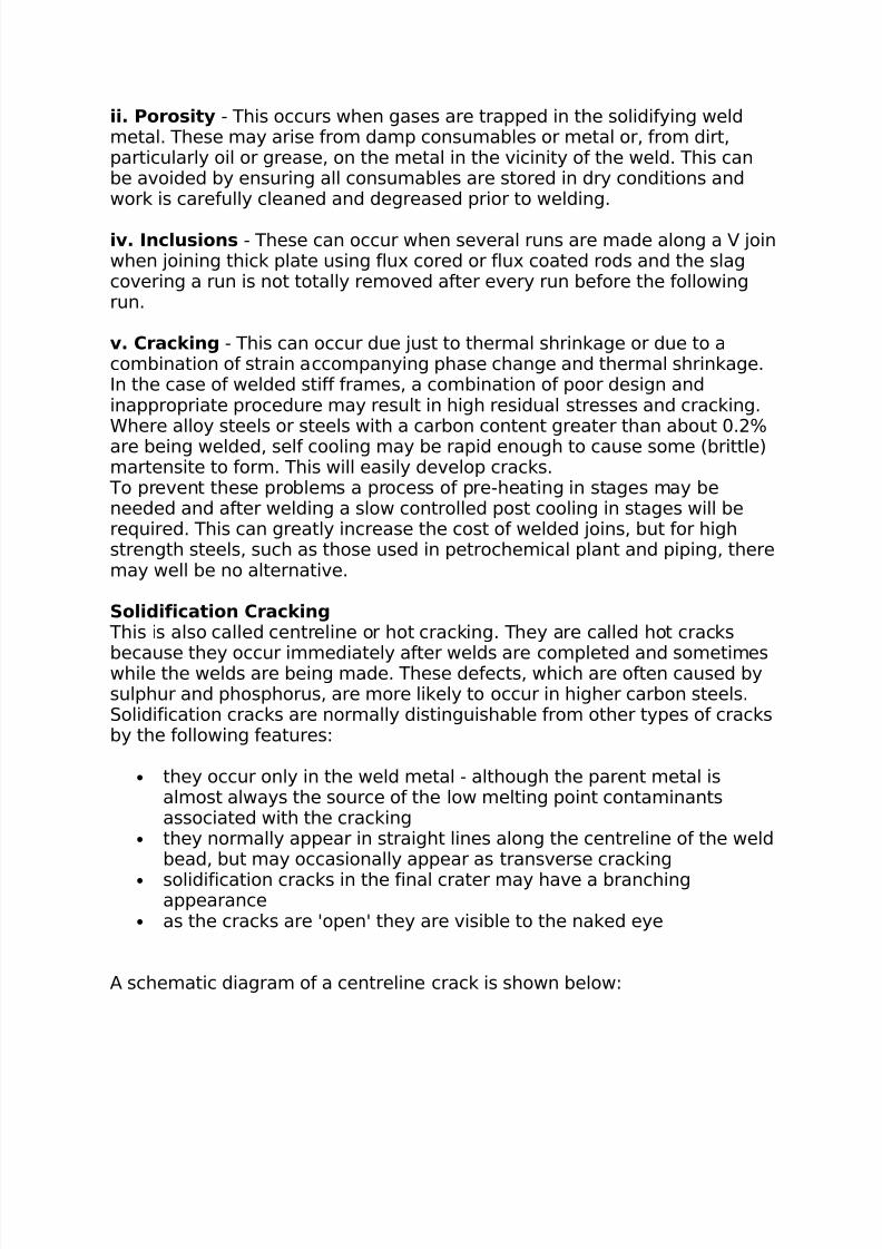
Pipe Body Crack:
Pipe Body Cracking is caused by various means,including chemical action (Stress Corrosion Cracking).Failure occurs when crack becomes unstable.
The installation of a PETROSLEEVE® permanentlyreduces the stress state in the material surrounding thedefect, removing the possibility for crack extension.
Weld Defect:Weld defects are caused by poor workmanship. Failureoccurs when the strength of the weld is not sufficient to
counteract the applied forces.
The installation of a PETROSLEEVE® permanentlyreduces the stress state in the material surrounding thedefect, as well as providing support to the weld.
The PETROSLEEVE® provides permanent mechanicalsupport to the weld area and reduces the strain inducedin the weld by the external forces.
Grind Defect: A grind defect is caused by mechanically removingmetal from the surface of the pipe material, resulting inlocalized thinning of the pipe wall. In addition, stressconcentrators could be present on the metal surface.Failure occurs first by bulging (yielding) at the grindingarea, followed by rupture of the steel membrane. Additionally, the presence of stress concentrators couldact as initiation points for rupture at lower strain levels.
The installation of a PETROSLEEVE® prevents bulging
by permanently providing mechanical support to thelocalized thinned section. The sleeve also eliminatesmetal movement (fatigue), and reduces the straininduced in the material by the external forces.
Leaking/Through-wallDefect A leak occurs when a hole in the pipe wall allows the
liquid or pipeline product (i.e. oil or gas) to escape, whilethe pipe wall continues to contain the internal pressurepreventing a rupture from occurring. Both leakingdefects and active internal corrosion will proceed
through the the wall of the pipeline if left unrepaired.
7/31/2019 Welds Errors
http://slidepdf.com/reader/full/welds-errors 3/8
At present, development is underway to research andtest a unique technique using the PETROSLEEVE®Repair System to repair both leaking defects and active
internal corrosion.
Welding Defects
1. Introduction
Common weld defects include:
• i. Lack of fusion• ii. Lack of penetration or excess penetration• iii. Porosity• iv. Inclusions• v. Cracking• vi. Undercut• vii. Lamellar tearing
Any of these defects are potentially disastorous as they can all give rise tohigh stress intensities which may result in sudden unexpected failure belowthe design load or in the case of cyclic loading, failure after fewer loadcycles than predicted.
2. Types of Defects i and ii. - To achieve a good quality join it is essential that the fusion zoneextends the full thickness of the sheets being joined. Thin sheet materialcan be joined with a single pass and a clean square edge will be asatisfactory basis for a join. However thicker material will normally neededges cut at a V angle and may need several passes to fill the V with weld
metal. Where both sides are accessible one or more passes may be madealong the reverse side to ensure the joint extends the full thickness of themetal.Lack of fusion results from too little heat input and / or too rapid traverse of the welding torch (gas or electric).Excess penetration arises from to high a heat input and / or too slowtransverse of the welding torch (gas or electric). Excess penetration -burning through - is more of a problem with thin sheet as a higher level of skill is needed to balance heat input and torch traverse when welding thinmetal.
7/31/2019 Welds Errors
http://slidepdf.com/reader/full/welds-errors 4/8
ii. Porosity - This occurs when gases are trapped in the solidifying weldmetal. These may arise from damp consumables or metal or, from dirt,particularly oil or grease, on the metal in the vicinity of the weld. This canbe avoided by ensuring all consumables are stored in dry conditions andwork is carefully cleaned and degreased prior to welding.
iv. Inclusions - These can occur when several runs are made along a V joinwhen joining thick plate using flux cored or flux coated rods and the slagcovering a run is not totally removed after every run before the followingrun.
v. Cracking - This can occur due just to thermal shrinkage or due to acombination of strain accompanying phase change and thermal shrinkage.In the case of welded stiff frames, a combination of poor design andinappropriate procedure may result in high residual stresses and cracking.Where alloy steels or steels with a carbon content greater than about 0.2%are being welded, self cooling may be rapid enough to cause some (brittle)martensite to form. This will easily develop cracks. To prevent these problems a process of pre-heating in stages may beneeded and after welding a slow controlled post cooling in stages will berequired. This can greatly increase the cost of welded joins, but for highstrength steels, such as those used in petrochemical plant and piping, theremay well be no alternative.
Solidification Cracking This is also called centreline or hot cracking. They are called hot cracks
because they occur immediately after welds are completed and sometimeswhile the welds are being made. These defects, which are often caused bysulphur and phosphorus, are more likely to occur in higher carbon steels.Solidification cracks are normally distinguishable from other types of cracksby the following features:
• they occur only in the weld metal - although the parent metal isalmost always the source of the low melting point contaminantsassociated with the cracking
• they normally appear in straight lines along the centreline of the weldbead, but may occasionally appear as transverse cracking
• solidification cracks in the final crater may have a branchingappearance
• as the cracks are 'open' they are visible to the naked eye
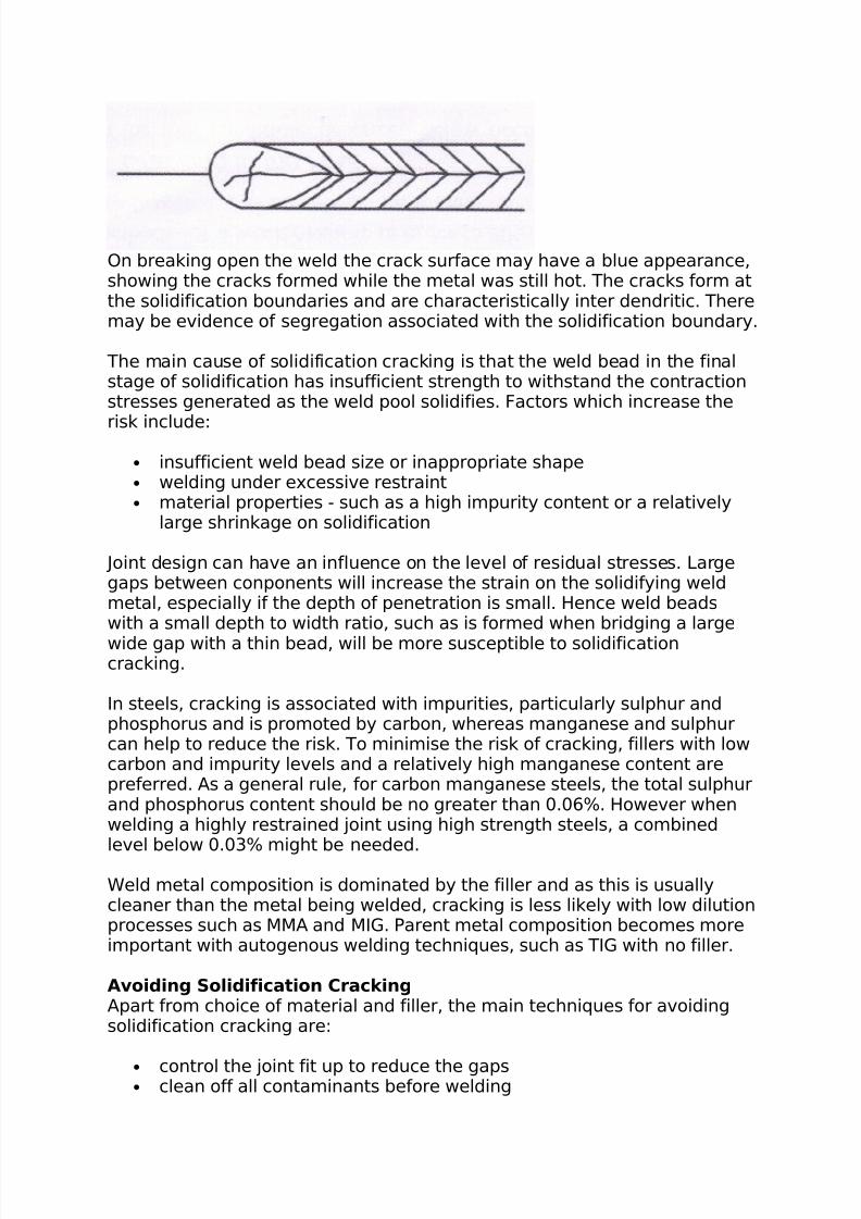
A schematic diagram of a centreline crack is shown below:
7/31/2019 Welds Errors
http://slidepdf.com/reader/full/welds-errors 5/8
On breaking open the weld the crack surface may have a blue appearance,showing the cracks formed while the metal was still hot. The cracks form atthe solidification boundaries and are characteristically inter dendritic. Theremay be evidence of segregation associated with the solidification boundary.
The main cause of solidification cracking is that the weld bead in the finalstage of solidification has insufficient strength to withstand the contractionstresses generated as the weld pool solidifies. Factors which increase the
risk include:
• insufficient weld bead size or inappropriate shape• welding under excessive restraint• material properties - such as a high impurity content or a relatively
large shrinkage on solidification
Joint design can have an influence on the level of residual stresses. Largegaps between conponents will increase the strain on the solidifying weldmetal, especially if the depth of penetration is small. Hence weld beadswith a small depth to width ratio, such as is formed when bridging a large
wide gap with a thin bead, will be more susceptible to solidificationcracking.
In steels, cracking is associated with impurities, particularly sulphur andphosphorus and is promoted by carbon, whereas manganese and sulphurcan help to reduce the risk. To minimise the risk of cracking, fillers with lowcarbon and impurity levels and a relatively high manganese content arepreferred. As a general rule, for carbon manganese steels, the total sulphurand phosphorus content should be no greater than 0.06%. However whenwelding a highly restrained joint using high strength steels, a combinedlevel below 0.03% might be needed.
Weld metal composition is dominated by the filler and as this is usuallycleaner than the metal being welded, cracking is less likely with low dilutionprocesses such as MMA and MIG. Parent metal composition becomes moreimportant with autogenous welding techniques, such as TIG with no filler.
Avoiding Solidification Cracking Apart from choice of material and filler, the main techniques for avoidingsolidification cracking are:
• control the joint fit up to reduce the gaps• clean off all contaminants before welding
7/31/2019 Welds Errors
http://slidepdf.com/reader/full/welds-errors 6/8
• ensure that the welding sequence will not lead to a buildup of thermally induced stresses
• choose welding parameters to produce a weld bead with adequatedepth to width ratio or with sufficient throat thickness (fillet weld) toensure the bead has sufficient resistance to solidificatiuon stresses.
Recommended minimum depth to width ratio is 0.5:1• avoid producing too large a depth to width ratio which will encourage
segregation and excessive transverse strains. As a rule, weld beadswith a depth to width ratio exceeds 2:1 will be prone to solidificationcracking
• avoid high welding speeds (at high current levels) which increasesegregation and stress levels accross the weld bead
• at the run stop, ensure adequate filling of the crater to avoid anunfavourable concave shape
Hydrogen induced cracking (HIC) - also referred to as hydrogencracking or hydrogen assisted cracking, can occur in steels duringmanufacture, during fabrication or during service. When HIC occurs as aresult of welding, the cracks are in the heat affected zone (HAZ) or in theweld metal itself.
Four requirements for HIC to occur are:
• a) Hydrogen be present, this may come from moisture in any flux orfrom other sources. It is absorbed by the weld pool and diffuses int othe HAZ.
•
b) A HAZ microstructure susceptible to hydrogen cracking.• c) Tensile stresses act on the weld• d) The assembly has cooled to close to ambient - less than 150oC
HIC in the HAZ is often at the weld toe, but can be under the weld bead orat the weld root. In fillet welds cracks are normally parallel to the weld runbut in butt welds cracks can be transverse to the welding direction.
vi Undercutting - In this case the thickness of one (or both) of the sheetsis reduced at the toe of the weld. This is due to incorrect settings /
procedure. There is already a stress concentration at the toe of the weldand any undercut will reduce the strength of the join.
vii Lamellar tearing - This is mainly a problem with low quality steels. Itoccurs in plate that has a low ductility in the through thickness direction,which is caused by non metallic inclusions, such as suphides and oxidesthat have been elongated during the rolling process. These inclusions meanthat the plate can not tolerate the contraction stresses in the shorttransverse direction.Lamellar tearing can occur in both fillet and butt welds, but the most
vulnerable joints are 'T' and corner joints, where the fusion boundary isparallel to the rolling plane.
7/31/2019 Welds Errors
http://slidepdf.com/reader/full/welds-errors 7/8
These problem can be overcome by using better quality steel, 'buttering'the weld area with a ductile material and possibly by redesigning the joint.
3. Detection Visual Inspection
Prior to any welding, the materials should be visually inspected to see thatthey are clean, aligned correctly, machine settings, filler selection checked,etc.As a first stage of inspection of all completed welds, visual inspected undergood lighting should be carried out. A magnifying glass and straight edgemay be used as a part of this process.
Undercutting can be detected with the naked eye and (provided there isaccess to the reverse side) excess penetration can often be visuallydetected.
Liquid Penetrant Inspection Serious cases of surface cracking can be detected by the naked eye but formost cases some type of aid is needed and the use of dye penetrantmethods are quite efficient when used by a trained operator. This procedure is as follows:
• Clean the surface of the weld and the weld vicinity• Spray the surface with a liquid dye that has good penetrating
properties• Carefully wipe all the die off the surface•
Spray the surface with a white powder• Any cracks will have trapped some die which will weep out and
discolour the white coating and be clearly visible
X - Ray Inspection Sub-surface cracks and inclusions can be detected 'X' ray examination. Thisis expensive, but for safety critical joints - eg in submarines and nuclearpower plants - 100% 'X' ray examination of welded joints will normally becarried out.
Ultrasonic Inspection
Surface and sub-surface defects can also be detected by ultrasonicinspection. This involves directing a high frequency sound beam throughthe base metal and weld on a predictable path. When the beam strikes adiscontinuity some of it is reflected beck. This reflected beam is receivedand amplified and processed and from the time delay, the location of a flawestimated.Porosity, however, in the form of numerous gas bubbles causes a lot of lowamplitude reflections which are difficult to separate from the backgroundnoise.Results from any ultrasonic inspection require skilled interpretation.
7/31/2019 Welds Errors
http://slidepdf.com/reader/full/welds-errors 8/8
Magnetic Particle Inspection This process can be used to detect surface and slightly sub-surface cracksin ferro-magnetic materials (it can not therefore be used with austeniticstainless steels). The process involves placing a probe on each side of the area to be
inspected and passing a high current between them. This produces amagnetic flux at right angles to the flow of the current. When these lines of force meet a discontinuity, such as a longitudinal crack, they are divertedand leak through the surface, creating magnetic poles or points of attraction. A magnetic powder dusted onto the surface will cling to theleakage area more than elsewhere, indicating the location of anydiscontinuities. This process may be carried out wet or dry, the wet process is moresensitive as finer particles may be used which can detect very smalldefects. Fluorescent powders can also be used to enhance sensitivity whenused in conjunction with ultra violet illumination.
4. Repair Any detected cracks must be ground out and the area re-welded to give therequired profile and then the joint must be inspected again.