msatcs302a – detail bolts & welds - australian ... · pdf filemsatcs302a –...
TRANSCRIPT
MEM30001A
2011
Use computer aided drafting systems to
produce basic engineering drawings.

MSATCS302A – Detail bolts & welds
BlackLine Design 1st February 2012 – Version 2 Page 2 of 24
First Published February 2011
2nd Edition February 2013
This work is copyright. Any inquiries about the use of this material should be
directed to the writer.
Edition 1 – February 2011
Edition 2 – February 2013
MSATCS302A – Detail bolts & welds
BlackLine Design 1st February 2012 – Version 2 Page 3 of 24
Conditions of Use:
Unit Resource Manual
Manufacturing Skills Australia Courses
This Student’s Manual has been developed by BlackLine Design for use in the Manufacturing
Skills Australia Courses.
All rights reserved. No part of this publication may be printed or transmitted in any form
by any means without the explicit permission of the writer.
Statutory copyright restrictions apply to this material in digitally and hard copy.
Copyright BlackLine Design 2012
MSATCS302A – Detail bolts & welds
BlackLine Design 1st February 2012 – Version 2 Page 4 of 24
Feedback:
Your feedback is essential for improving the quality of these manuals.
Please advise the appropriate industry specialist of any changes, additions, deletions or
anything else you believe would improve the quality of this Student Workbook. Don’t
assume that someone else will do it. Your comments can be made by photocopying the
relevant pages and including your comments or suggestions.
Forward your comments to:
BlackLine Design
Sydney NSW 2000

MSATCS302A – Detail bolts & welds
BlackLine Design 1st February 2012 – Version 2 Page 5 of 24
Aims of the Competency Unit
This unit covers the skills and knowledge required to detail bolts and welds for structural
steelwork connections consistent with design specifications.
This unit applies to a structural steel detailer who has to detail various types of bolts and
welds for structural steelwork connections. The detailing may be done manually or by using
CAD and/or proprietary steel detailing software.
The unit may apply to structural steel detailing carried out for residential, commercial,
industrial or mining fabrication and construction projects. The unit assumes that knowledge
of basic technical drawing conventions and procedures such as view, dimensioning, drawing
layout, etc. is already held.
Work is conducted according to defined procedures. Work may be conducted in small to
large scale enterprises and may involve individual and team activities.
This unit requires the application of skills associated with planning and organising to
complete structural steel detail drawings. Communication and numeracy skills are used to
refer to patterns and specifications and complete and label sketches. Self management skills
are used to ensure conformance of own work to quality standards
Unit Hours
27 Hours
Prerequisites:
MEM09002B Interpret technical drawing
MEM05051A Select welding processes
MSATCS301A Interpret architectural and engineering design
specifications for structural steel detailing
MSATCS302A – Detail bolts & welds
BlackLine Design 1st February 2012 – Version 2 Page 6 of 24
MSATCS302A – Detail bolts & welds
BlackLine Design 1st February 2012 – Version 2 Page 7 of 24
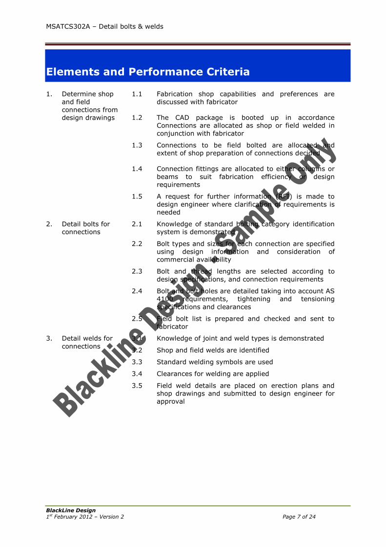
Elements and Performance Criteria
1. Determine shop
and field
connections from
design drawings
1.1
Fabrication shop capabilities and preferences are
discussed with fabricator
1.2
The CAD package is booted up in accordance
Connections are allocated as shop or field welded in
conjunction with fabricator
1.3
Connections to be field bolted are allocated and
extent of shop preparation of connections decided
1.4 Connection fittings are allocated to either columns or
beams to suit fabrication efficiency or design
requirements
1.5 A request for further information (RFI) is made to
design engineer where clarification of requirements is
needed
2. Detail bolts for
connections
2.1 Knowledge of standard bolting category identification
system is demonstrated
2.2 Bolt types and sizes for each connection are specified
using design information and consideration of
commercial availability
2.3 Bolt and thread lengths are selected according to
design specifications, and connection requirements
2.4 Bolt and bolt holes are detailed taking into account AS
4100 requirements, tightening and tensioning
specifications and clearances
2.5 Field bolt list is prepared and checked and sent to
fabricator
3. Detail welds for
connections
3.1 Knowledge of joint and weld types is demonstrated
3.2 Shop and field welds are identified
3.3 Standard welding symbols are used
3.4 Clearances for welding are applied
3.5 Field weld details are placed on erection plans and
shop drawings and submitted to design engineer for
approval
MSATCS302A – Detail bolts & welds
BlackLine Design 1st February 2012 – Version 2 Page 8 of 24
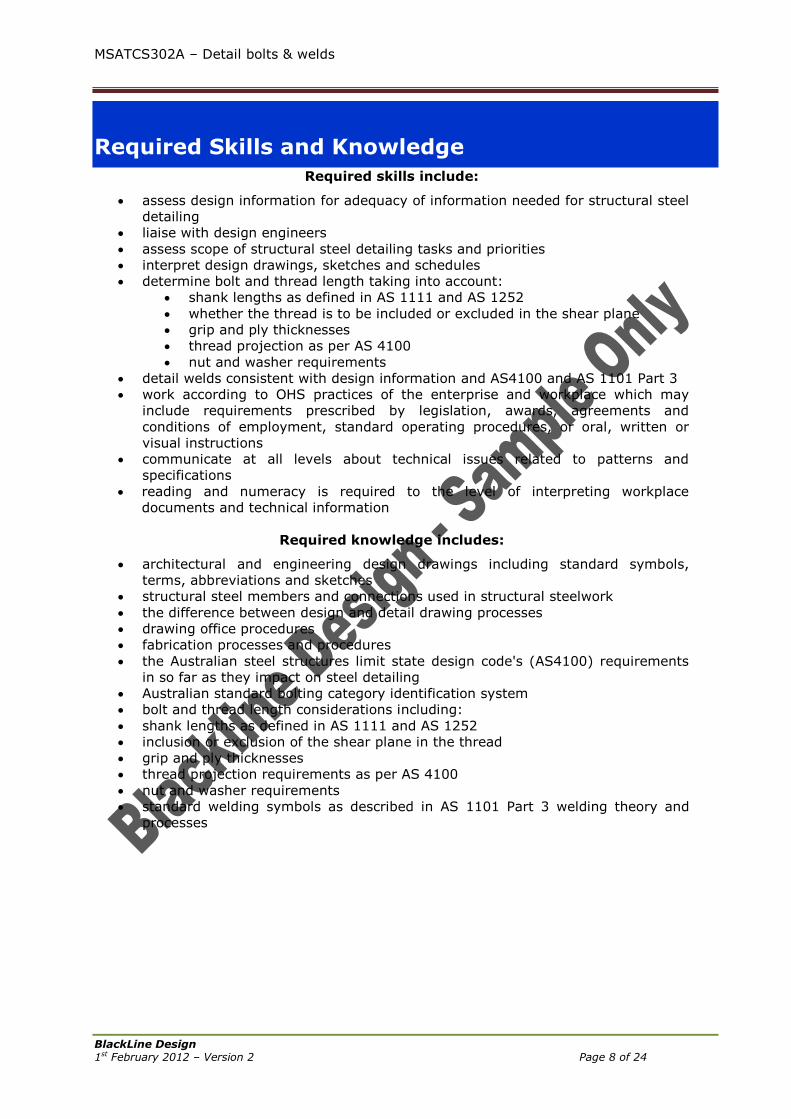
Required Skills and Knowledge
Required skills include:
assess design information for adequacy of information needed for structural steel
detailing
liaise with design engineers
assess scope of structural steel detailing tasks and priorities
interpret design drawings, sketches and schedules
determine bolt and thread length taking into account:
shank lengths as defined in AS 1111 and AS 1252
whether the thread is to be included or excluded in the shear plane
grip and ply thicknesses
thread projection as per AS 4100
nut and washer requirements
detail welds consistent with design information and AS4100 and AS 1101 Part 3
work according to OHS practices of the enterprise and workplace which may
include requirements prescribed by legislation, awards, agreements and
conditions of employment, standard operating procedures, or oral, written or
visual instructions
communicate at all levels about technical issues related to patterns and
specifications
reading and numeracy is required to the level of interpreting workplace
documents and technical information
Required knowledge includes:
architectural and engineering design drawings including standard symbols,
terms, abbreviations and sketches
structural steel members and connections used in structural steelwork
the difference between design and detail drawing processes
drawing office procedures
fabrication processes and procedures
the Australian steel structures limit state design code's (AS4100) requirements
in so far as they impact on steel detailing
Australian standard bolting category identification system
bolt and thread length considerations including:
shank lengths as defined in AS 1111 and AS 1252
inclusion or exclusion of the shear plane in the thread
grip and ply thicknesses
thread projection requirements as per AS 4100
nut and washer requirements
standard welding symbols as described in AS 1101 Part 3 welding theory and
processes
MSATCS302A – Detail bolts & welds
BlackLine Design 1st February 2012 – Version 2 Page 9 of 24
Table of Contents
Conditions of Use: ............................................................................................. 3 Unit Resource Manual .................................................................................. 3 Manufacturing Skills Australia Courses ........................................................... 3
Feedback: .......................................................................................................... 4
Acknowledgement: ............................................................................................ 4
Table of Contents .............................................................................................. 5
Lesson Program:................................................................................................ 8
Terminology: ..................................................................................................... 9
Australian Standard Codes: ..............................................................................12
Lesson 1 – Bolts ...............................................................................................13 Required Skills .......................................................................................... 13 Required Knowledge .................................................................................. 13 Introduction: ............................................................................................ 13 Types of Bolts: .......................................................................................... 14 Dimensions of Bolts: .................................................................................. 15 Identification of Bolts: ................................................................................ 15 Bolting Categories: .................................................................................... 15 Bolt Length Selection: ................................................................................ 16
Plain Shank Lengths: ............................................................................. 16 Threads Included in Shear Plane: ............................................................ 16 Threads Excluded From Shear Plane: ...................................................... 14
Thread Projection: ..................................................................................... 19 Available Bolt Sizes: .................................................................................. 19 Coronet Load Indicators: ............................................................................ 20 Bolt Designation on Drawings: .................................................................... 22 Skill Practice Exercise MSATCS302-SP-101: ................................................. 23
Lesson 2 – Hole Details ....................................................................................26 Required Skills .......................................................................................... 26 Required Knowledge .................................................................................. 26 Bolt Holes: ............................................................................................... 26 Minimum Edge Distance: ............................................................................ 27 Maximum Edge Distance: ........................................................................... 27 Minimum Pitch of Bolts: .............................................................................. 28 Maximum Pitch of Bolts: ............................................................................. 28 Washer Requirements: ............................................................................... 28 Indication on Drawings: ............................................................................. 28 Skill Practice Exercise MSATCS302-SP-201 to MSATCS302-SP-205: ................ 29
MSATCS302-SP-201:............................................................................. 29 MSATCS302-SP-202:............................................................................. 29 MSATCS302-SP-203:............................................................................. 29 MSATCS302-SP-204:............................................................................. 30 MSATCS302-SP-205:............................................................................. 30
Lesson 3 – Welding Symbols ............................................................................31 Required Skills .......................................................................................... 31

MSATCS302A – Detail bolts & welds
BlackLine Design 1st February 2012 – Version 2 Page 10 of 24
Required Knowledge .................................................................................. 31 Welding: .................................................................................................. 31 Welding Processes: .................................................................................... 32 The Welding Symbol: ................................................................................. 32
Cranked Arrow: .................................................................................... 33 Weld Symbols and Applications: .................................................................. 34
Fillet Weld: .......................................................................................... 34 Square Butt: ........................................................................................ 34 Bevel Butt: .......................................................................................... 35 “V” Butt: .............................................................................................. 36 “J” Butt: .............................................................................................. 37 “U” Butt: ............................................................................................ .38
Supplementary Welding Symbols: ............................................................... 38 All Around Weld: ................................................................................... 38 On-Site Weld: ...................................................................................... 39 Stud Weld:........................................................................................... 39 Plug & Slot Welds: ................................................................................ 40 Bead Weld: .......................................................................................... 41 Surfacing: ............................................................................................ 41 Backing Bar: ........................................................................................ 42 Flush, Convex & Concave Surface Contour: .............................................. 43 Tail: .................................................................................................... 44
Ancillary Welding Symbols: ......................................................................... 44 Intermittent Weld: ................................................................................ 44 Staggered Weld: ................................................................................... 44 Compound Weld: .................................................................................. 45
Skill Practice Exercise MSATCS302-SP-301 to MSATCS302-SP-303: ................ 46 MSATCS302-SP-301:............................................................................. 46 MSATCS302-SP-302:............................................................................. 47 MSATCS302-SP-303:............................................................................. 48
Practice Competency Test: ...............................................................................49
Addendums: .....................................................................................................50 Addendum 1 – Metric Hexagon Commercial Bolts & Set Screws: ...................... 50 Addendum 2 – High Strength Structural Bolts: .............................................. 51 Addendum 3 – Coronet Load Indicators ........................................................ 52 Addendum 4 – Flat Round Washers for High Strength Bolts: ........................... 53 Addendum 5 – Minimum Thread Lengths: ..................................................... 54

MSATCS302A – Detail bolts & welds
Lesson 1 – Bolts
BlackLine Design 1st February 2012 – Version 2 Page 11 of 24
Lesson 1 – Bolts
Required Skills Name the Australian standards used for bolts in the construction of steel structures.
Specify the two types of bolts used in the construction of steel structures.
Identify Commercial and High Strength Structural bolts.
Select bolts to suit specific bolt categories.
Calculate the length of a bolt to conform to structural requirements and Australian
Standards.
Required Knowledge Australian Standards.
Types of bolts and materials.
Interpreting detail and design drawings to determine lengths of bolts.
Reading tables associated with structural steel sections.
Introduction: Bolts are used to connect beams, girders, trusses, columns, and other structural and non-
structural members which form a complicated structure are designed to support certain
loads. Each of these members must transmit its load through structural joints to supporting
members.
Joints are formed by bolting or welding two or more members together where the
connection material, dimensions, angles, plates and/or structural sections are detailed.
The two methods for connecting structural and non-structural members in this unit are
Bolting and Welding:
Bolts:
Bolting creates a flexible or rigid connection that can be assembled or disassembled
as required. Bolts are used widely for making connections in structural steelwork,
especially field connections. An understanding of all aspects of the use of bolts is
vital to the designing, detailing, fabrication and erection of steel structures.
Welds:
Welding forms a rigid connection and is the process in which fusion (melting) occurs
by heating with an electrical arc that is generated between an electrode/rod and the
surfaces of the parent materials.
Bolts and welds are normally designed and specified by an engineer. The selection of the
bolt is determined by:
The nature of the forces to be resisted.
Design capacity of available bolt types.
Ammount of joint slippage desired.
Degree of flexibility/rigidity desired in the joint.
Cost of the installed fastener.
MSATCS302A – Detail bolts & welds
Lesson 1 – Bolts
BlackLine Design 1st February 2012 – Version 2 Page 12 of 24
Types of Bolts: Two types of metric bolts are used in the fabrication, erection of structural steel structures
in Australia.
1. Commercial (Strength Grade 4.6) bolts to AS/NZS1111
2. High strength structural (Steel Grade 8.8) bolt to AS/NZS1252
Commercial bolts are made of low carbon steel with mechanical properties similar to that of
Grade 250 (MPa) material.
High strength bolts are made by heat treating, quenching and tempering medium carbon
steel. Accordingly, heating or welding a commercial bolt will cause no significant change in
its properties (strength) but either process will cause a significant degradation in the
mechanical properties of high strength structural bolts.
Structural steelwork uses a limited range of size of bolts. Commercial bolts are commonly
used in the following diameters:
M12 – purlin, and girt applications.
M16 – cleats and relatively lightly loaded brackets.
M20 – general structural connections and holding down bolts.
M24 – general structural connections and holding down bolts.
M30 – holding down bolts.
M36 – holding down bolts.
The high strength structural bolt is most commonly used in the following diameters:
M16 – designed connections in small members.
M20 – flexible and rigid connections.
M24 – flexible and rigid connections.
M30 & M36 and larger – these sizes should be avoided when full tensioning is
required, since on-site tensioning can be difficult and may require special equipment.
Dimensions of Bolts:
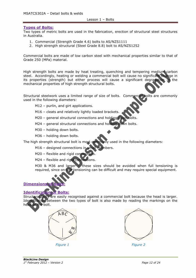
Identification of Bolts: Structural bolts are easily recognised against a commercial bolt because the head is larger.
Identification between the two types of bolt is also made by reading the markings on the
head of the bolt.
Figure 1
Figure 2
MSATCS302A – Detail bolts & welds
Lesson 1 – Bolts
BlackLine Design 1st February 2012 – Version 2 Page 13 of 24
Figure 1 shows a High Strength Bolt where the manufacturer’s name, the grade and three
radial lines are displayed on the head while Figure 2 is a Commercial bolt with no
distinguishing data.
Bolting Categories: A standard bolting category identifying system is used throughout Australia for use by steel
designers and detailers.
Category 4.6/S refers to commercial bolts of Strength Grade 4.6 and tightened to a
snug-tight condition with a standard torque wrench.
Category 8.8/S refers to any bolt of Strength Grade 8.8 and tightened to a snug-
tight condition with a standard torque wrench.
Category 8.8/T and 8.8/TB (or 8.8T both types) refer specifically to high strength
structural bolts of Strength Grade 8.8 and fully tensioned in a controlled manner to
the requirements of AS4100.
The system of category designation identifies the bolt being used by its strength grade
designation (4.6 or 8.8) and the installation procedure by a supplementary letter (s = snug,
T = full tensioning). For 8.8/S categories, the type of joint is identified by an additional
letter (F = friction type joint, B = bearing type point).
High strength bolts can be specified in three ways:
Snug tightened – category 8.8/S.
Fully tensioned, friction type – category 8.8/TF.
Fully tensioned, bearing type – category 8.8/TB
The level of tensioning is the same for both 8.8/TF and 8.8/TB categories.
In practice, 8.8/S category would mainly be used in flexible joints where the extra capacity
of the stronger bolt (compared to 4.6/S category) makes it economical. It is recommended
that 8.8/TF category be used only on rigid joints where a no-slip joint is essential. 8.8/TF is
the only category requiring attention to the faying surfaces. Design engineers’ drawings
and workshop detail drawings should both contain notes summarising the category
designations.
Bolting
Category
Method of
Tensioning
Minimum Bolt
Tensile
Strength
(MPa)
Minimum
Bolt Yield
Strength
(MPa)
Bolt Name Bolt Standard
Specification
4.6/S Snug
400 240 Commercial AS/NZS1111
8.8/S
830 660
High
Strength
Steel
AS/NZS1252 8.8/T**
Full
Tensioning
** Includes 8.8/TF (friction type joint) and 8.8/TB (bearing type joint)
Bolt Length Selection: The responsibility for selecting bolt lengths for each connection usually rests with the steel
detailer. In selecting bolt lengths, consideration must be given to whether the sheer plane
cuts across the threaded or unthreaded section of the bolt. The advantages and
disadvantages of both must be clearly understood by the steel detailer. Most connections
are designed on the basis of threads being included in the shear plane. Where designers
specifically require threads to be excluded, the steel detailer must take additional care when
calculating bolt lengths to ensure this requirement is met.
MSATCS302A – Detail bolts & welds
Lesson 1 – Bolts
BlackLine Design 1st February 2012 – Version 2 Page 14 of 24
Plain Shank Lengths:
Plain shank bearing lengths for each type of bolt are defined in the relevant Australian
Standards (AS/NZS1111 and AS/NZS1252) as the distance from the bearing surface of the
bolt head to the last scratch of the thread.
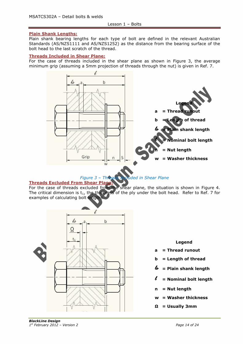
Threads Included in Shear Plane:
For the case of threads included in the shear plane as shown in Figure 3, the average
minimum grip (assuming a 5mm projection of threads through the nut) is given in Ref. 7.
Legend
a = Thread runout
b = Length of thread
ls = Plain shank length
l = Nominal bolt length
n = Nut length
w = Washer thickness
Figure 3 – Threads Included in Shear Plane
Threads Excluded From Shear Plane:
For the case of threads excluded from the shear plane, the situation is shown in Figure 4.
The critical dimension is t1, the thickness of the ply under the bolt head. Refer to Ref. 7 for
examples of calculating bolt lengths.
Legend
a = Thread runout
b = Length of thread
ls = Plain shank length
l = Nominal bolt length
n = Nut length
w = Washer thickness
Ω = Usually 3mm
MSATCS302A – Detail bolts & welds
Lesson 1 – Bolts
BlackLine Design 1st February 2012 – Version 2 Page 15 of 24
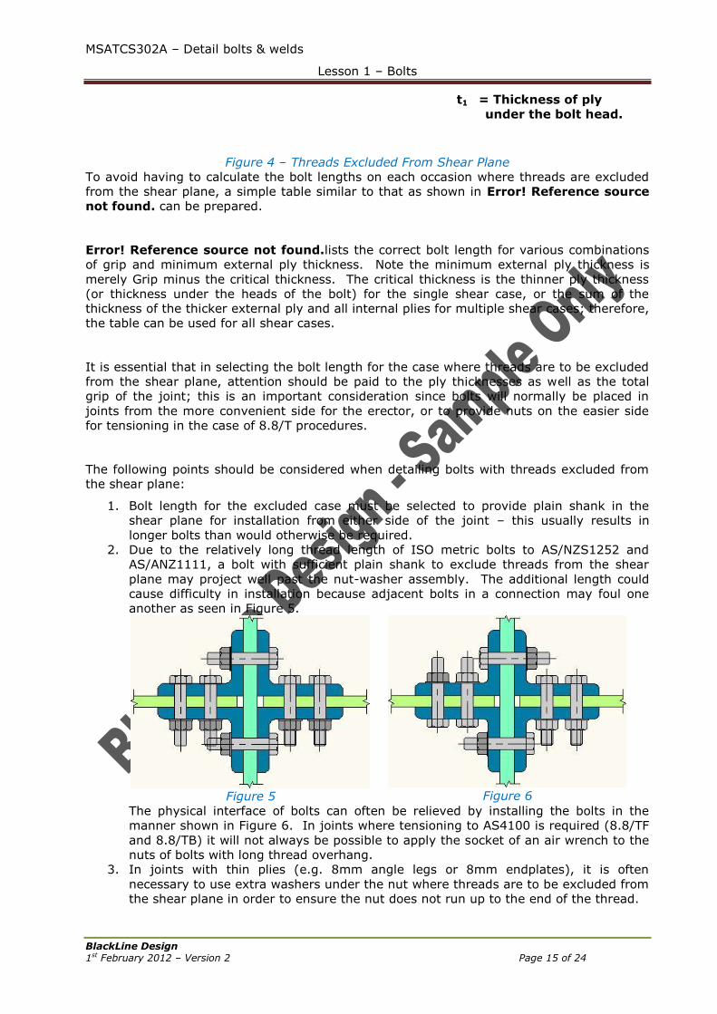
t1 = Thickness of ply
under the bolt head.
Figure 4 – Threads Excluded From Shear Plane
To avoid having to calculate the bolt lengths on each occasion where threads are excluded
from the shear plane, a simple table similar to that as shown in Error! Reference source
not found. can be prepared.
Error! Reference source not found.lists the correct bolt length for various combinations
of grip and minimum external ply thickness. Note the minimum external ply thickness is
merely Grip minus the critical thickness. The critical thickness is the thinner ply thickness
(or thickness under the heads of the bolt) for the single shear case, or the sum of the
thickness of the thicker external ply and all internal plies for multiple shear cases; therefore,
the table can be used for all shear cases.
It is essential that in selecting the bolt length for the case where threads are to be excluded
from the shear plane, attention should be paid to the ply thicknesses as well as the total
grip of the joint; this is an important consideration since bolts will normally be placed in
joints from the more convenient side for the erector, or to provide nuts on the easier side
for tensioning in the case of 8.8/T procedures.
The following points should be considered when detailing bolts with threads excluded from
the shear plane:
1. Bolt length for the excluded case must be selected to provide plain shank in the
shear plane for installation from either side of the joint – this usually results in
longer bolts than would otherwise be required.
2. Due to the relatively long thread length of ISO metric bolts to AS/NZS1252 and
AS/ANZ1111, a bolt with sufficient plain shank to exclude threads from the shear
plane may project well past the nut-washer assembly. The additional length could
cause difficulty in installation because adjacent bolts in a connection may foul one
another as seen in Figure 5.
Figure 5
Figure 6
The physical interface of bolts can often be relieved by installing the bolts in the
manner shown in Figure 6. In joints where tensioning to AS4100 is required (8.8/TF
and 8.8/TB) it will not always be possible to apply the socket of an air wrench to the
nuts of bolts with long thread overhang.
3. In joints with thin plies (e.g. 8mm angle legs or 8mm endplates), it is often
necessary to use extra washers under the nut where threads are to be excluded from
the shear plane in order to ensure the nut does not run up to the end of the thread.

MSATCS302A – Detail bolts & welds
Lesson 1 – Bolts
BlackLine Design 1st February 2012 – Version 2 Page 16 of 24
Figure 7
Figure 8
In Figure 8, the nut has been tightened to the end of the thread but there is a large
gap between the washer and the connection resulting in the connection being loose
which could cause failure in the connection. In Figure 7, additional washers have
been added under the bolt head to move the thread into the connection to ensure a
correct tightness is attained.
4. As the location of the plain shank relative to the shear plane position is critical for
the threads excluded case, such a joint is very sensitive to the bolt length selection;
this means that bolts have to be selected usually in length increments of 5mm and
results in the stocking of a great number of bolt lengths and the subsequent difficulty
in discharging correct bolts for a particular joint on site. Alternately, excessive
‘sticking-through’ must be accepted.
Thread Projection: AS4100 requires that the length of a bolt be such that at least one clear thread projects
through the nut and that at least one thread plus the thread run-out is clear beneath the
nut after tightening to either /S or /T bolting category.
t = minimum one thread (one pitch)
Figure 9 – AS4100 Minimum Requirements for Thread Projection
The methods of calculation to meet the requirements are presented in Ref. 7.
The minimum projection through the nut of at least on thread pitch is intended to ensure
that full engagement of the nut thread is achieved. While this is accepted good practice for
/S bolting category, it is crucial with /T category in order to achieve the specified minimum
bolt tension.
MSATCS302A – Detail bolts & welds
Lesson 1 – Bolts
BlackLine Design 1st February 2012 – Version 2 Page 17 of 24
The clearance under the nut is intended to ensure that a nut is never tightened against the
thread run-out on the bolt which constitutes the end of the threaded portion of the bolt. If
the clearance is not provided, the nut will not sit firmly against the washer and, in the case
of /T category, the necessary turn-of-nut may not have been achieved.
Available Bolt Sizes: Where possible, bolt sizes that are readily available should be used. Table 1 provides a
summary of readily available commercial grade bolt sizes, i.e. bolt diameter and length
options while Table 2 shows the same information for high strength structural bolts.
Diamet
er
mm
Nominal Lengths
4
0
4
5
5
0
5
5
6
0
6
5
7
0
7
5
8
0
8
5
9
0
9
5
10
0
11
0
12
0
13
0
14
0
15
0
M12 X X X X X X X X X X X X X X X X X X
M16 X X X X X X X X X X X X X X X X X X
M20 X X X X X X X X X X X X X X X X X X
M24 X X X X X X X X X X X X X X X X
M30 X X X X X X X X X X X X
M32 X X X X X X X X X
Usually supplied as full thread bolts
Table 1 – Readily Available Commercial Grade Bolt Sizes
Diamete
r
mm
Nominal Lengths
4
5
5
0
5
5
6
0
6
5
7
5
7
5
8
0
8
5
9
0
9
5
10
0
11
0
12
0
13
0
14
0
15
0
M16 X X X X X X X X X X X X X X X X X
M20 X X X X X X X X X X X X X X X X X
M24 X X X X X X X X X X X X X X X X X
M30 X X X X X X X X X X X X X X X X
M36 X X X X X X X X X X X X
Bolts with shortened thread lengths
Minimum body length = 0.5 x bolt diameter
Table 2 - Readily Available Structural High Strength Grade Bolt Sizes
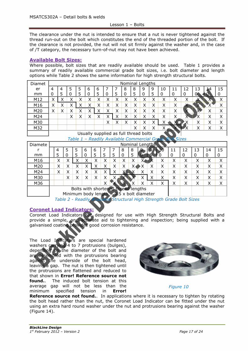
Coronet Load Indicators: Coronet Load Indicators are designed for use with High Strength Structural Bolts and
provide a simple, and accurate aid to tightening and inspection; being supplied with a
galvanised coating provides good corrosion resistance.
The Load Indicators are special hardened
washers carrying 4 to 7 protrusions (bulges),
depending on the diameter of the bolt and
are assembled with the protrusions bearing
against the underside of the bolt head,
leaving a gap. The nut is then tightened until
the protrusions are flattened and reduced to
that shown in Error! Reference source not
found.. The induced bolt tension at this
average gap will not be less than the
minimum specified tension in Error!
Reference source not found.. In applications where it is necessary to tighten by rotating
the bolt head rather than the nut, the Coronet Load Indicator can be fitted under the nut
using an extra hard round washer under the nut and protrusions bearing against the washer
(Figure 14).
Figure 10
MSATCS302A – Detail bolts & welds
Lesson 1 – Bolts
BlackLine Design 1st February 2012 – Version 2 Page 18 of 24
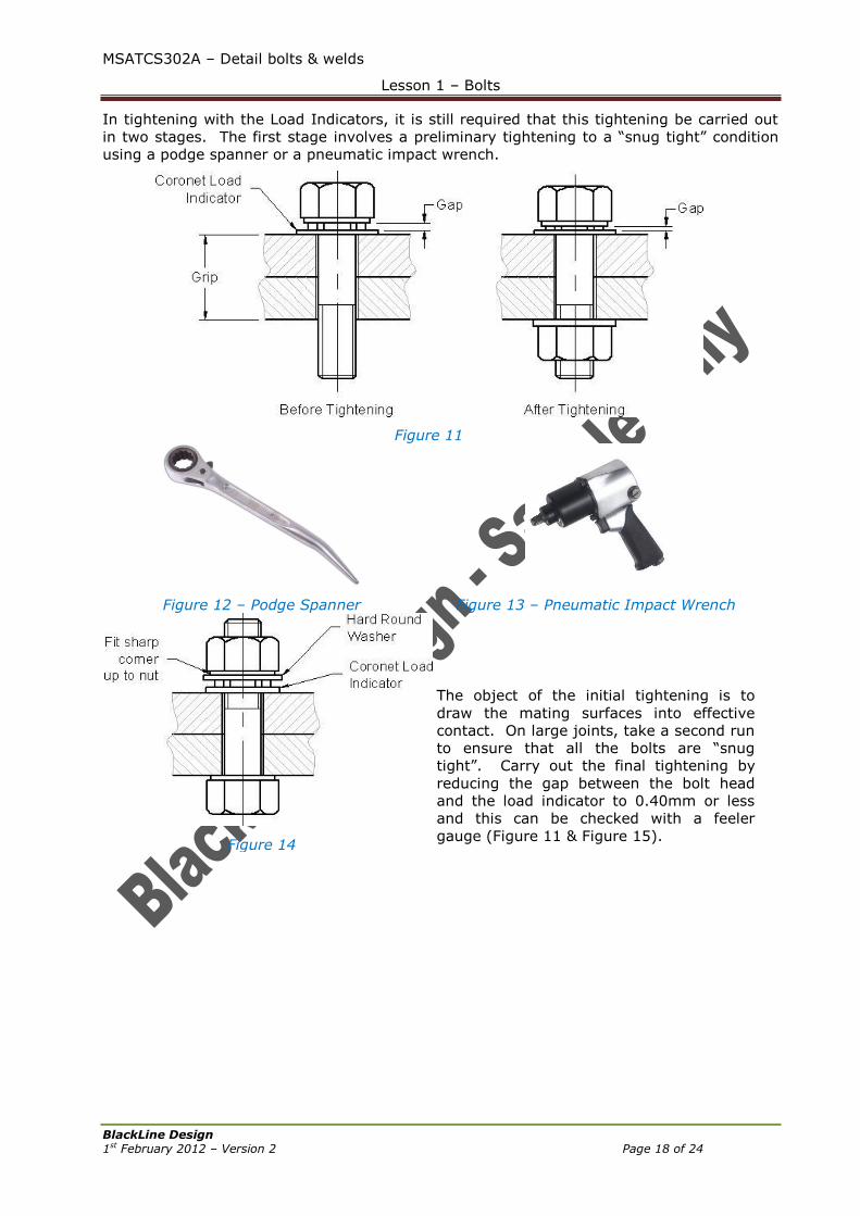
In tightening with the Load Indicators, it is still required that this tightening be carried out
in two stages. The first stage involves a preliminary tightening to a “snug tight” condition
using a podge spanner or a pneumatic impact wrench.
Figure 11
Figure 12 – Podge Spanner
Figure 13 – Pneumatic Impact Wrench
Figure 14
The object of the initial tightening is to
draw the mating surfaces into effective
contact. On large joints, take a second run
to ensure that all the bolts are “snug
tight”. Carry out the final tightening by
reducing the gap between the bolt head
and the load indicator to 0.40mm or less
and this can be checked with a feeler
gauge (Figure 11 & Figure 15).
MSATCS302A – Detail bolts & welds
Lesson 1 – Bolts
BlackLine Design 1st February 2012 – Version 2 Page 19 of 24
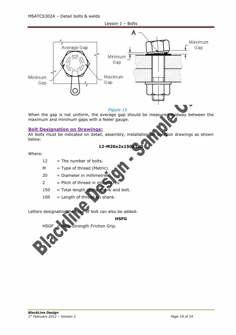
Figure 15
When the gap is not uniform, the average gap should be measured midway between the
maximum and minimum gaps with a feeler gauge.
Bolt Designation on Drawings: All bolts must be indicated on detail, assembly, installation on erection drawings as shown
below:
12-M20x2x150x100
Where:
12 = The number of bolts.
M = Type of thread (Metric).
20 = Diameter in millimetres.
2 = Pitch of thread in millimetres.
150 = Total length of the shank and bolt.
100 = Length of thread on shank.
Letters designating the type of bolt can also be added:
HSFG
HSGF = High Strength Friction Grip.
MSATCS302A – Detail bolts & welds
Lesson 1 – Bolts
BlackLine Design 1st February 2012 – Version 2 Page 20 of 24
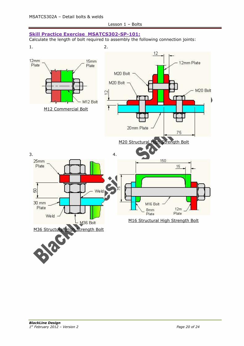
Skill Practice Exercise MSATCS302-SP-101: Calculate the length of bolt required to assembly the following connection joints:
1.
M12 Commercial Bolt
2.
M20 Structural High Strength Bolt
3.
M36 Structural High Strength Bolt
4.
M16 Structural High Strength Bolt
MSATCS302A – Detail bolts & welds
Lesson 1 – Bolts
BlackLine Design 1st February 2012 – Version 2 Page 21 of 24
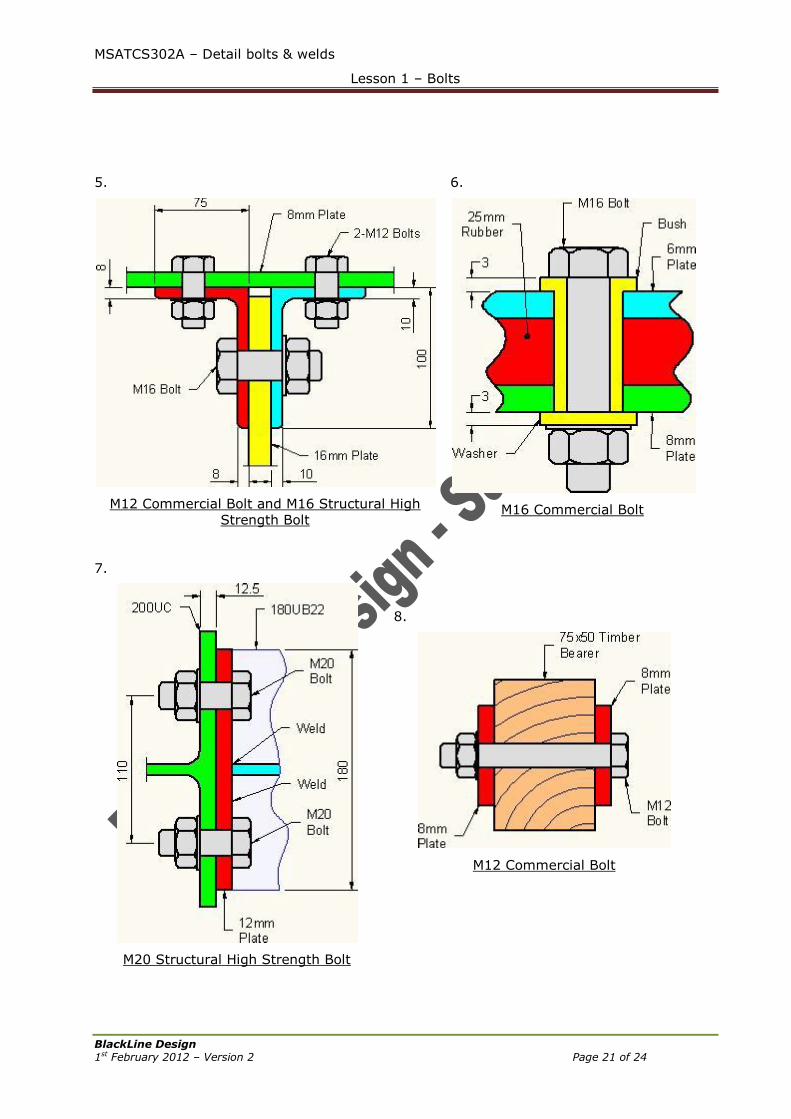
5.
M12 Commercial Bolt and M16 Structural High
Strength Bolt
6.
M16 Commercial Bolt
7.
M20 Structural High Strength Bolt
8.
M12 Commercial Bolt

MSATCS302A – Detail bolts & welds
Lesson 1 – Bolts
BlackLine Design 1st February 2012 – Version 2 Page 22 of 24
9.
M12 Commercial Bolt
10.
M20 Structural High Strength Bolt
MSATCS302A – Detail bolts & welds
Lesson 1 – Bolts
BlackLine Design 1st February 2012 – Version 2 Page 23 of 24
Addendums:
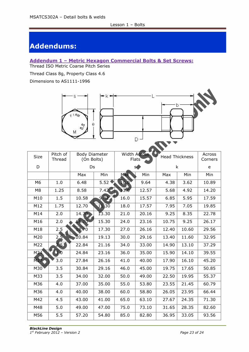
Addendum 1 – Metric Hexagon Commercial Bolts & Set Screws: Thread ISO Metric Coarse Pitch Series
Thread Class 8g, Property Class 4.6
Dimensions to AS1111-1996
Size Pitch of
Thread
Body Diameter
(On Bolts)
Width Across
Flats Head Thickness
Across
Corners
D Ds s k e
Max Min Max Min Max Min Min
M6 1.0 6.48 5.52 10.0 9.64 4.38 3.62 10.89
M8 1.25 8.58 7.42 13.0 12.57 5.68 4.92 14.20
M10 1.5 10.58 9.42 16.0 15.57 6.85 5.95 17.59
M12 1.75 12.70 11.30 18.0 17.57 7.95 7.05 19.85
M14 2.0 14.70 13.30 21.0 20.16 9.25 8.35 22.78
M16 2.0 16.70 15.30 24.0 23.16 10.75 9.25 26.17
M18 2.5 18.70 17.30 27.0 26.16 12.40 10.60 29.56
M20 2.5 20.84 19.13 30.0 29.16 13.40 11.60 32.95
M22 2.5 22.84 21.16 34.0 33.00 14.90 13.10 37.29
M24 3.0 24.84 23.16 36.0 35.00 15.90 14.10 39.55
M27 3.0 27.84 26.16 41.0 40.00 17.90 16.10 45.20
M30 3.5 30.84 29.16 46.0 45.00 19.75 17.65 50.85
M33 3.5 34.00 32.00 50.0 49.00 22.50 19.95 55.37
M36 4.0 37.00 35.00 55.0 53.80 23.55 21.45 60.79
M36 4.0 40.00 38.00 60.0 58.80 26.05 23.95 66.44
M42 4.5 43.00 41.00 65.0 63.10 27.67 24.35 71.30
M48 5.0 49.00 47.00 75.0 73.10 31.65 28.35 82.60
M56 5.5 57.20 54.80 85.0 82.80 36.95 33.05 93.56
MSATCS302A – Detail bolts & welds
Lesson 1 – Bolts
BlackLine Design 1st February 2012 – Version 2 Page 24 of 24
M64 6.0 65.20 62.80 95.0 92.8 41.95 39.05 104.86
All dimensions are in millimetres. See Error! Reference source not found. for nominal
thread lengths.