welding symbols ch. 38. types of drawings –working drawings – drawing of objects used to produce...
TRANSCRIPT
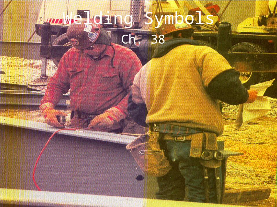
Welding SymbolsCh. 38

• Types of drawings– Working drawings – drawing of objects used to produce
projects/structures in the shop
– Assembly drawings – shows the object to be made as it would appear in a fully assembled, ready to use form.
– Detail drawings are made of each different part in the assembly process.
• The Theory of Orthographic Projection– Presenting an object and all of its sides and makeup on a flat
piece of paper.
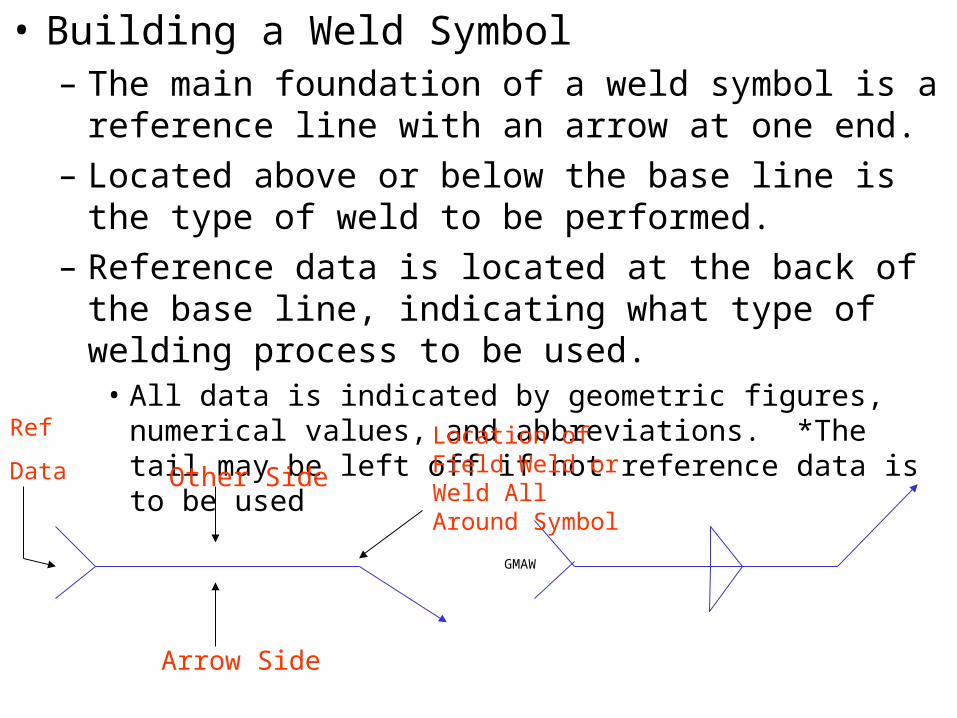
• Building a Weld Symbol– The main foundation of a weld symbol is a reference line
with an arrow at one end.
– Located above or below the base line is the type of weld to be performed.
– Reference data is located at the back of the base line, indicating what type of welding process to be used.
• All data is indicated by geometric figures, numerical values, and abbreviations. *The tail may be left off if not reference data is to be used
GMAW
Other Side
Arrow Side
Ref
Data
Location of Field Weld or Weld All Around Symbol

• The most important factor in a welding symbol is the type of weld, in relationship with the type of joint to be used.– There are five main types of joints
• Butt, Corner, Lap, T, & Edge
• Welds are classified into fillet, plug, spot, seam, or groove – They are broken down further with each weld having its own symbol.

QUIZ

• The direction of the arrow is not important, it may run up or down.
• When both sides of the joint are to be welded the symbol appears above and below the line.
• Combining Weld Symbols– Some joints may require more than one type of weld on a particular joint.

• Size of fillet welds– The width of a fillet weld is shown to the left of the weld symbol and is
expressed in fractions, decimals, or metric units.
– The length of the weld is shown to the right of the weld symbol. When both sides are to be welded the same both are shown.
3/810
3/8 10
¼ ¼

• When a fillet weld with unequal legs is required, the size of the legs is placed in parentheses.
• The length & pitch increments of intermittent welds are shown to the right of the weld symbol. The first figure represents the length of the weld section and the second figure the pitch (center-to-center spacing)
(1/4x1/2)
3/8 6 - 10
Length Pitch

Size of groove welds
• There are several types of groove welds. Their sizes (effective throat in fractions, decimals or millimeters) are shown here.– For a single-groove and symmetrical double-groove welds which extend
completely through the metal being joined, no size is included on the weld symbol.
– For groove welds which extend only partly through members being joined or on nonsymmetrical double-groove joints, weld size (effective throat) is shown in parentheses to the left of the weld symbol.
.38mm
EFFECTIVE THROAT (.38)

• A dimension not in parentheses when placed to the left of the weld symbol indicates the depth of the bevel only. When both the effective throat and bevel depth are indicated, the groove bevel depth is located to the left of the effective throat size.
• Root opening of groove joints is shown inside the weld symbol. The included angle of the bevel is placed below or above the weld symbol.
.25 (.38)
.38 Effective Throat
.25
Groove
Depth
1/16
60°
1/16
60°
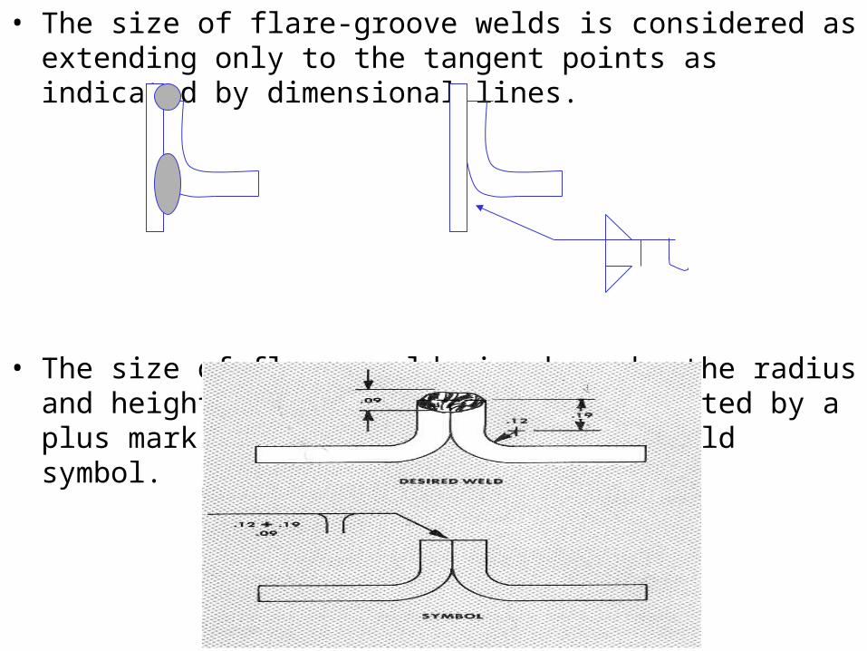
• The size of flare-groove welds is considered as extending only to the tangent points as indicated by dimensional lines.
• The size of flange welds is shown by the radius and height of the flange and is separated by a plus mark placed to the left of the weld symbol.

• The size of plug welds is shown to the left of the weld symbol, the depth, when less than full, on the inside of the weld symbol, the center-to-center spacing (pitch) to the right of the weld symbol, and the included angle of countersink below the symbol.


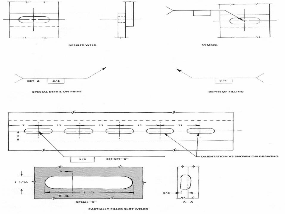
• Slot welds – length, width, spacing angle of countersink and location of slot welds are not shown on the symbol. This data is included by showing a special detail on the print. If the slots are partly filled, the depth of filling is shown inside.

• Size of spot welds– Spot welds are dimensioned either by size or strength.
Size is designated as the diameter of the weld.


• Size of seam welds– Seam welds are dimensioned either by size or strength.
The length of the seam weld is placed to the right of the weld symbol. The pitch of intermittent seam welds is shown to the right of the length dimension.


• Weld-all around symbol– When a weld is to extend completely around a joint, a
small circle is placed where the arrow connects the reference line.

• Field weld symbol– Welds to be made in the field are shown by a darkened
triangular flag at the juncture of the reference line and arrow. The flag always points toward the tail of the arrow.
• Field welds are welds not to be performed in the shop or at the place of initial construction.

• Reference Tail– The tail is included only when some definite welding
specifications, procedure, weld or cutting process needs to be called out.
• Examples: AC/DC welding, SMAW, & GMAW etc.


• Back or Backing Welds– Refers to the weld made on the opposite side of the
regular weld. Back welds are occasionally specified to insure adequate penetration and provide additional strength to a joint. This particular symbol is included opposite the weld symbol. No dimensions of back or backing welds except height of reinforcement is shown on the weld symbol.

• Melt-thru welds– When complete joint penetration of the weld through the
material is required in welds made from one side only, a special melt-thru weld symbol is placed opposite the regular weld symbol. No dimension of melt-thru, except height of reinforcement, is shown on the symbol.

• Surfacing welds– Welds whose surfaces must be built up by a single or
multiple passes welding are provided with a surfacing weld symbol. The height of the built-up surface is indicated by a dimension placed to the left of the surfacing symbol.


Chapter Review1. Indicate the meaning of the following symbols.
1. A = fillet both sides, B= fillet arrow side weld all around, C= fillet other side
2. What type of weld do these symbols indicate?
2. A = seam, B = plug, C = fillet, D = v-groove

3. How would you interpret these symbols?
3. A = the size of the bead is ¼, fillet weld on the arrow side, B = fillet weld 3 ½ long or length of the bead, C = plug or slot weld ¼ depth.
4. These symbols represent what weld specifications?
4. A = .25” size in diameter spot weld arrow side, B = V-groove arrow side, C = u-groove other side

5. What do welds designated with the following symbols represent?
5. A = v- groove arrow side 3/8 size of bevel depth ¼ is effective throat size, B = square joint arrow side & an edge flange joint on the other side, C = square groove with 1/16 gap in the metal
6. What is the meaning of each of these symbols?
6. A = v-groove arrow side & 1/8 root opening v-groove other side, B = fillet arrow side ½ is the size of the bead with the length of 6.
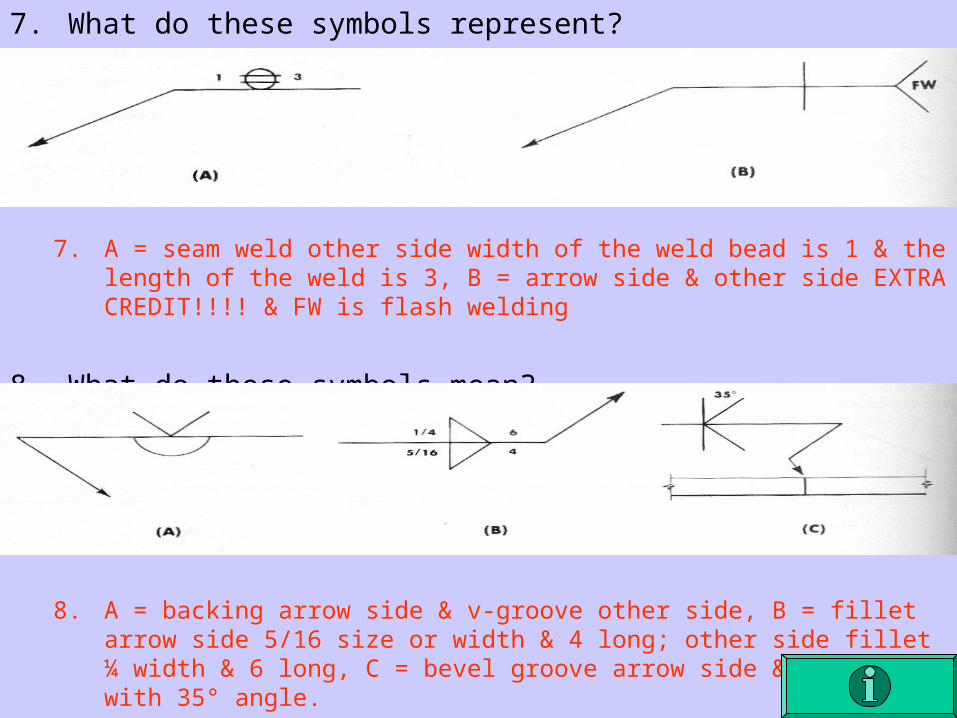
7. What do these symbols represent?
7. A = seam weld other side width of the weld bead is 1 & the length of the weld is 3, B = arrow side & other side EXTRA CREDIT!!!! & FW is flash welding
8. What do these symbols mean?
8. A = backing arrow side & v-groove other side, B = fillet arrow side 5/16 size or width & 4 long; other side fillet ¼ width & 6 long, C = bevel groove arrow side & other side with 35° angle.