weld symbols on drawings
TRANSCRIPT

Section
- ----......
5. WELD SYMBOLS 3, ANSI/AWS SPECIALS
6. LOCATION OF SYMBOLS 1, BUTT WELDS
7. LOCATION OF SYMBOLS 2, BUTT WELDS
8. LOCATION OF SYMBOLS 3, FILLET WELDS
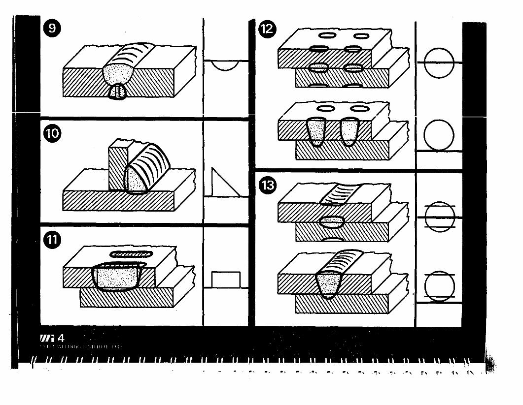
9. SUPPLEMENTARY SYMBOLS 1, WELD SURFACE SYMBOLS
10. SUPPLEMENTARY SYMBOLS 2
11. SUPPLEMENTARY SYMBOLS 3, ANSI/AWS
12. DIMENSIONS 1, BUTT WELD METAL
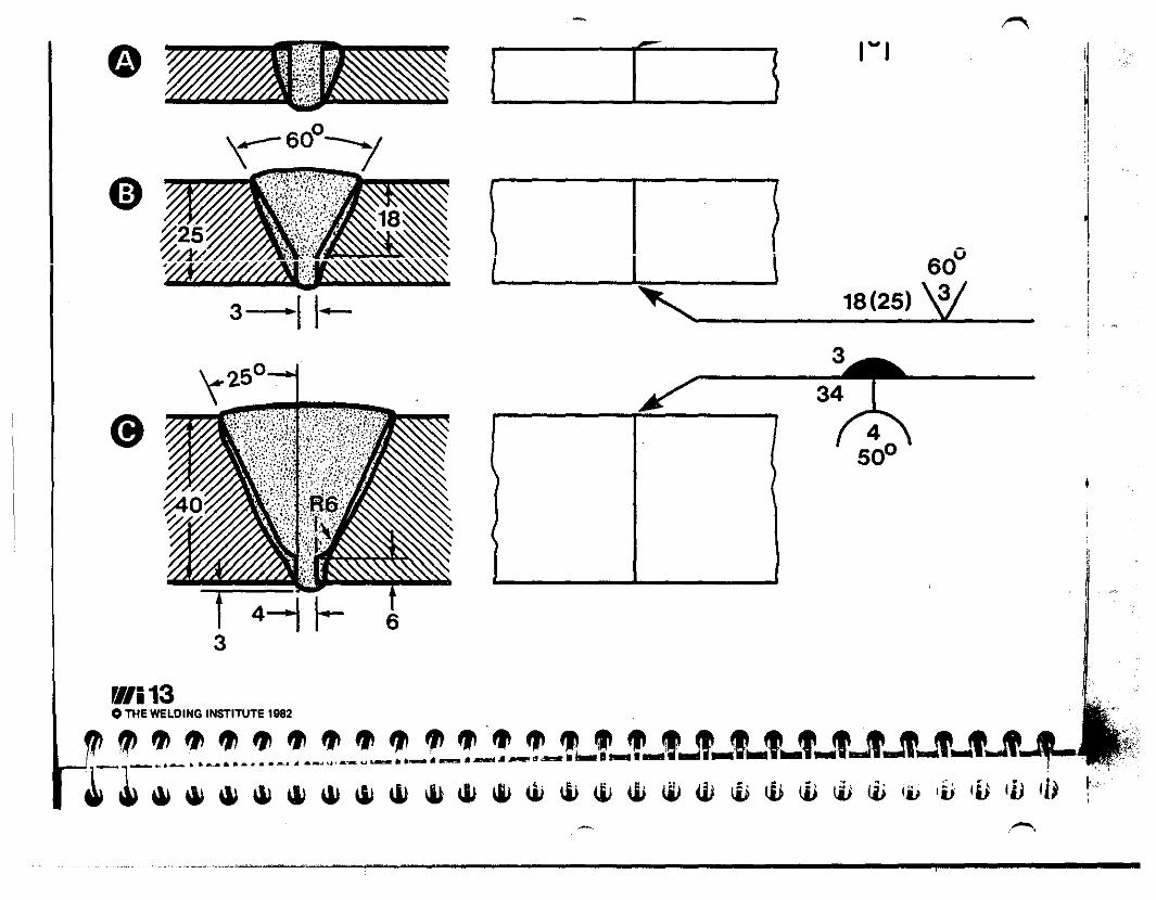
13. DIMENSIONS 2, BUTT WELD PREPARATION, ANSI/AWS
14. DIMENSIONS 3, FILLET WELD, TRANSVERSE
15. DIMENSIONS 4, FI LLET WELD, TRANSVERSE
16. DIMENSIONS 5, FILLET WELD, LONGITUDINAL, ISO/BS
17. DIMENSIONS 6, FILLET WELD, LONGITUDINAL, ANSI/AWS
18. PROCESS IDENTIFICATION
19. STUD WELDS
20. SPOT AND SEAM WELDS
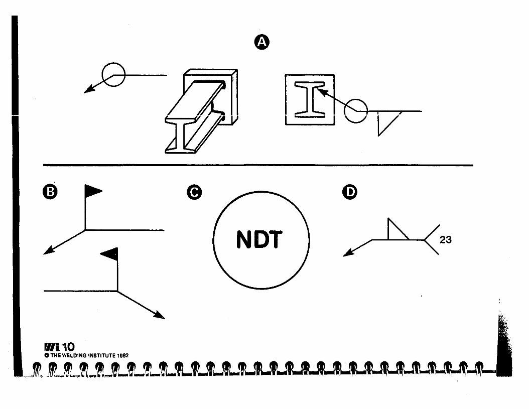
21. NONDESTRUCTIVE TESTING SYMBOLS, ANSI/AWS
22. EXERCISE 1, FLANGE ENDED PIPE
23. EXERCISE 2, VESSEL
24.. EXERCISE 3, TANK
25. EXERCISE 4, BEAM
1. THE NEED TO SPECIFY WELDS
2. THE ADVANTAGES OF SYMBOLS
3. WELD SYMBOLS 1, BUTT/GROOVE WELDS
WELD SYMBOLS ON DRAWINGS
SET D

-
BOLT WELDjHERE /HERE
I 1-.-.,,: :-_-.:--=..\ I J)'
...--- _"---- ----;.I
U U U U
rt/i1o THE WELDING INSTITUTE 1982

1-6PREPARATIONFULLPENETRATIONWELD
IT t..l-:/,.:.....---_I
.ut.Jt.Jt.~., ..I I;~,.....,.
6[7
1----- _
1------- ,
M15X25 BOLT
W/i2 ~OTHE WELDING INSTITUTE 1982
'LH>_~_?~"_t_t_Lt-r...'_t.JLfIW!
(9--f ----t

-
II
,~-_., ...~- .._-----,-------------------------

-

Arrow line y,..._--=-'---(5) "ReferenceARROW SIDE line
OTHER SIDE
M6 'o THE WELDING INSTITUTE 1982 ii
, ~ ••• " " " •• .,,, "4t" "..... "4\ .... it .. " " ". E.

-OTHER SIDESYMBOL
ARROW SIDESYMBOL
n...-.-.../
TITLE
3rd ANGLE
--
"/i 7C THE WELDING INSTITUTE 1982
_~a....I'I ....~_"-f..L'L"_L,,-,...t_'_J"...t.'....,... '.~-'-'~~~~~WWW~W~~www~ili~W~~~~w~W '
..............~'~._............---------------~--

W/i8OTHE WELDING INSTITUTE 1982

v
~-
-") \r,'. oJ
[Iii 9o THE WELDING INSTITUTE 1982
.' _"'_,~~f~LLLL~"'~'"'. !! ' ,
~~~~~~~~~~~~W~~~~~~
~/i10o THE WELDING INSTITUTE 1982
IJ~, ,I I '-J V

- .--
M
MR
,M
~1i11OTHE WELDING INSTITUTE 1982
.-oIIl"""lII_~~tt.~a-L!Jl.tJL'_'_Lf...'--'-'..AUI!-'-'-'-1t~, ;
~ ~ ~ \l) \l) ~ ~ ~ I&) ~ ~ W ~ II) tJj \II W IV tli tli lJ) 111 ij; Iii IlJ

v --~~P
12
8
8
W/i12o THE WELDING INSTITUTE 1982 , ;,""~ ~~_.~.,~._~_!_~_?J_~_,_,_,_,_,_,.Jt_""'_'.Jt.Jt~~-L'"
-G
c=
'''''' If I {:1I
:1
1
0\ I i
i
i( I \ 60° ,
"- 18(25) W
Hi
I
./i13o THE WELDING INSTITUTE 1982 . ~,
11'_"_!_~ __~_.!_.~__!__!~~-~_~_~_T_'l-T_1'_'Jt_,-,-,-,-,-,-,-,,,,,,-+ '..~ ~ ~ ~ ~ \ll ~ \ll ~ ~ ~ ~ iii w IV W W W W W W W ti; 11) IV tjj Ii) Ii) 11$ t
"-'-"'-~~'--....,----------------,.------

14 20t\.
~/i14oTHE WELDING INSTITUTE 1882
2019f'\.19

2020
3,4,5,6,8,10,12,16,18,20,22,25
,\
6) (10x20)
.~~fA_'-'~'~L~,-,...'.JL'-'-''''''-I-f-'-If1~~ ,~ \il \il ~ \II \il Ii; ~ ~ \l;. Ii; U; \iJ \i} Ii; Ii> w \i,l ~ I;; Ii) til i~ I;) I~ iZi I
~/i15C THE WELDING INSTITUTE 1982
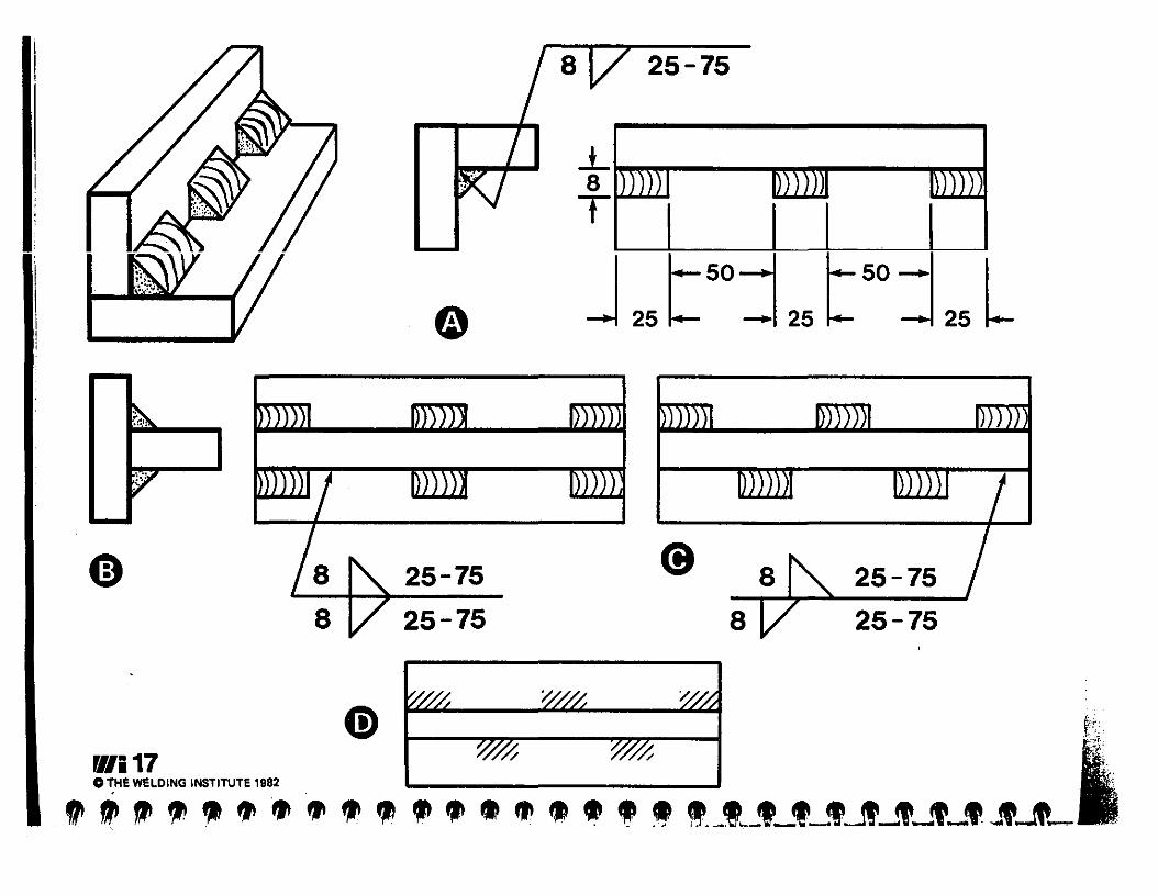
25-75
25-75
25-7525-75
25-75
~.. ~l.
V,

~/i18C THE WELDING INSTITUTE 1982
ARCWELOJNGSHIELOEOMETAL ARC WELDING
FLUX CORED ARC WELDINGSUBMERGED ARC WELDING
GAS METAL ARC WE LOING
GAS TUNGSTEN ARC WELDING" PLASMAARCWF=LD!I\!G
,RESISTANCE WELDING';iJ;';·F{I~SISTANCESF'.OTWELDING
RES.iSTANCESEAMWE LDI NG'PROJECTIONWELDINGFLASHWELDING
OXYFUEL GAS WELDINGOXYACETYLENE WELDING
FRICTION WELDINGFORGE WE1.DING
. THERMITWELDINGELECTROSLAG WELDING
"'STUDARC WELDINGBRAZINGSOLDERING
~.
a111'lIa ~~
AWSMAW
FCAWSAW
GMAW
GTAW
RWRSW
RSEWRPW
FW
OFWOAW
FRWFOW
TWESW
SWBS

Be)~3 ~--
........Nn I
PTPRT
RTUTVT
SymbolAET
ETLT
MT
- ------+-1-...... - __I- ......-
- -----.""
-RT PT
____ P VT+UT
Type of testACOUSTIC EMISSIONEDDY CURRENTLEAKMAGNETIC PARTICLENEUTRON HAuiOuHAPHiCPENETRANTPROOFRADIOGRAPHICULTRASONICVISUAL
W/i 21c THe We~DING INSTITUTe 1982 ,,"
I ''''fIl ••• fJI.fJ\'''''II~tI\tI\~~~(t.ftfi\~~~~~~~ ~- _. __ .i_ ... .. ~--- .. -. -~ ~ i ::: :'; ",",',

------
4..........~~~ ..........~Ll_i.
~~lt
All dimensions in millimetres
FLANGE ENDED PIPE
~::::t------ - ~-~8"---..-j
Single 'J' welds 10 deep
~/i 22C TH E WE LD ING INSTITUTE 1982

SECTION 23: EXERCISE 2, VESSEL
23 (Base transparency+2 overlays)
BASE TRANSPARENCYSymbols representing ",!elds to be made: letters in circles are for ease of reference below only.
Problem 1. Describe welds to be made, with sketches where necessary.
Comments1 The standard used for welding symbols has not been identified: there are six <;i~d" ;"d;~~~:~~~
that it is to ANSI/AWS.A: process abbreviation in fork is alphabetical.B, C, 0: 3 x 'melt-thru' symbols.Band 0: 2 x 'radiographic test' symbol.
2 A: stud arc welding, confirmed by studs on drawing.
3 Band 0: single-V butt weld with melt-thru, ground flush inside and radiographed.
4 C: single-bevel butt weld, stub pipe only bevelled, (set-on branch), with melt-thru, ground flushinside.
5 E: fillet weld, of 6mm leg length, both sides of joint. See sketches on overlay (a) forinterpretation.
a OVERLAY: possible interpretations of flange to tube joint E.F: this is consistent with the weld symbol, but the view does not show the expected projectionof the tube through the flange: also a form unlikely to be used, because of clearance problems.G, H: consistent with weld symbol and drawing. To decide between these two, it would benecessary to have details of the flange.
Problem 2. Modify symbols to conform to BS 499: Part 2: 1980, with joint as at H.
b OVERLAY: symbols to BS, solution to problem 2.I: symbol replacing A.J: symbol replacing B: note that BS can only specify NOT, not specifically radiography. Asthere is no 'melt·thru' symbol, only full penetration and a flat rear face can be specified: thesymbol requirements would be met by welding to produce a substantially flat surface, withoutfurther treatment.K: symbol replacing C }L: symbol replacing 0 see comments on J aboveM: Symbol replacing E
--

VESSEL
MATERIAL:STAINLESS STEELBODY6mmFLANGE 20mm
All dimensioN In millimetre.
\.J....._--+-__L/
<9_
/
~/i23o THE WELDING INSTITUTE 1982

SECTION 25: EXERCISE 4, BEAM
Problem. Sketch in welding details and symbols to BS 499: Part 2: 1980 (or other standard asinstructed).
B We cannot use a 'weld all round' symbol for the end flange joints, as it cannot go over top andbottom of the flanges, and it is interrupted by the cope·holes.
------ _ •• -_."-'-.' .. . " .' • I , . 1. _ L I __ 1\
UVt:t1LAY: ~ULU IIUI~. \LtHl~l~ III (,;1Il;1t:::J dlt: "':11 Icn:::I-';IIl:'c UCIVV·Y viil"Y·'.
BASE TRANSPARENCYSketch of beam, not to scale, to be assembled by manual metal arc welding in the shop and on site.
a
CommentsA Cope·holes have been introduced to avoid the need to dress welds where they meet other welds,
and to avoid welding up into corners, often a site for defects.
o A suggestion to be taken seriously! Apart from simplifying the drawing, complete shopfabrication can considerably reduce the costs of welding and of quality assurance.
C Similarly to B, the web-to·flange joints are in four sections, needing four arrows if they are to beshown individually.
The spacing in BS is not the pitch (here 300mm) but the distance between the ends of weldelements, here (300-100) = 200mm.
25 (Base transparency andoverlay)

f.>.
Ii""",,:
".' .....,\
SECTION X-X
Not to scale
FLANGES 15mmWEB 10mmEND PLATES 20mm
x
SKETCH FOR BEAM
xI
I
I
·1Top flange wold -I flnlshod flush
~- - tI
• 500mm
L_ I! -
End flanges: 12mm flll.t w.ldII' round (lnsld.)FI.nge.to....b: 12mm fllI.t w.lds100mm long, 300mm pitch .ochsid., alternately aach sid•.
...·--10·0m
.----5·1m1+--- 4·9m
~/i25C THE WELDING INSTITUTE 1982

aoctI· AND COllttlI·FUIIGI wne ........ ../
~'I .J-,." II\ ......... _..n ........-· .. _ ....
w .....'~ I- 'UII WlLDlIIIG ,,,....""""" ' ., _.04 ---~W1!C!P J·t•••It 1.... Ill"/" ~~""""OC' Y ./...'tlM....... ,....... _1"._.
_"".-c.....,. C••ll.ftl.--1Pf." ........___fli
-"' ,.-.._ --_..-......,..,.......''''-WOf ....-0 SYlllOI.
S·,··...·..·..........." .. -'-11. ""·COOl'OI,.It-S "==<::- ""...·, ••.. 1 , ~I'. S" ,
~':'.-..: :":..,;·t· 'l ..... '.:: ::::.::....... .J _.
......... _ ••,_, I_..... _.J 4'·
ll ..~~(,vGJlOOv( WUI)ING ""10\. 'NDIUIIIIIG !tOOl It(N(1I'u1Qtl
) •. l;X .......~. ;..... ";.,~;..."o........... '" •.,~__,................
l _, "."0.'- '-.,.- ._,
~ /A-.~ ~._, ~ .•.•., .
,~ , .HI .' ,
11_11&0 1111[..1"1111 PIU.a WlLDlIIIG "lIIOI...... " ~ ·_1 .--<,...J;.,C~, - ..
~.-t'-/'i".f=;<.' l£oo.. tSI '"
/ W·-·'---" , ..".111..1 _...-_.•_-...-....
·.O'HI,\I" _.nr<~...... lilt _.
''''11 "" - r-<_.- ., - .' .. -IOtll 11111 M
_. _.wII'
_. _.
..--._..,-_._._11.........-.......•...-Supplementary Symbols Used with Welding Symbols .
fIIlLl,l"lN IVIlSOL
.... " .... , -....'.... ' -(;...._fO ,'.' "'400"
/----1f(~_-<~ , , ...
_..
:.r-. ~~F--- .- ....._. E=.-=. =:
>~
._-::;-:::-::=..-.--.-c..-::z..E-====_..-..
.!-ti'·,·.. ,,-- _."., ,.. '..........., ,......._ , ......,'... , ""' .
---:'\.-.-~::::::e:-=-....-.......:.:::l..----
ru "Ill
"~IO _.-