welding - design, procedures, inspection (1)
TRANSCRIPT

TM 5-805-7
TECHNICAL MANUAL
WELDING
DESIGN, PROCEDURES AND INSPECTION
HEADQUARTERS, DEPARTMENT OF THE ARMY
20 MAY 1985

T M 5 - 8 0 5 - 7
REPRODUCTION AUTHORIZATION/RESTRICTIONS
This manual has been prepared by or for the Government and is public prop-erty and not subject to copyright.
Reprints or republications of this manual should include a credit substantiallyas follows: “Department of the Army Technical Manual TM 5-805-7, Welding:Design, Procedures and Inspection. ”

T M 5 - 8 0 5 - 7
WELDING: DESIGN, PROCEDURES AND INSPECTION
Chapter 1. INTRODUCTION
Purpose and scope . . . . . . . . . . . . . . . . . . . . . . . . . . . . . . . . . . . . . . . . . . . . . . . . . . . . . . . . . . . . . . . . . . . . . . . . . . . . . . . . . . . . . . . . . . . . . . . . . . . . . . . . . . . . . . . . . . . . . . . . .Welding applications . . . . . . . . . . . . . . . . . . . . . . . . . . . . . . . . . . . . . . . . . . . . . . . . . . . . . . . . . . . . . . . . . . . . . . . . . . . . . . . . . . . . . . . . . . . . . . . . . . . . . . . . . . . . . . . . . . . . .
Chapter 2.. DESIGN AND INSPECTION RESPONSIBILITIES
Designer responsibilities . . . . . . . . . . . . . . . . . . . . . . . . . . . . . . . . . . . . . . . . . . . . . . . . . . . . . . . . . . . . . . . . . . . . . . . . . . . . . . . . . . . . . . . . . . . . . . . . . . . . . . . . . . . . . . . .Contractor responsibilities . . . . . . . . . . . . . . . . . . . . . . . . . . . . . . . . . . . . . . . . . . . . . . . . . . . . . . . . . . . . . . . . . . . . . . . . . . . . . . . . . . . . . . . . . . . . . . . . . . . . . . . . . . . . .Inspection requirements . . . . . . . . . . . . . . . . . . . . . . . . . . . . . . . . . . . . . . . . . . . . . . . . . . . . . . . . . . . . . . . . . . . . . . . . . . . . . . . . . . . . . . . . . . . . . . . . . . . . . . . . . . . . . . . .
Chapter 3. WELDING PROCESSES
General . . . . . . . . . . . . . . . . . . . . . . . . . . . . . . . . . . . . . . . . . . . . . . . . . . . . . . . . . . . . . . . . . . . . . . . . . . . . . . . . . . . . . . . . . . . . . . . . . . . . . . . . . . . . . . . . . . . . . . . . . . . . . . . .Processes . . . . . . . . . . . . . . . . . . . . . . . . . . . . . . . . . . . . . . . . . . . . . . . . . . . . . . . . . . . . . . . . . . . . . . . . . . . . . . . . . . . . . . . . . . . . . . . . . . . . . . . . . . . . . . . . . . . . . . . . . . . . . . . . Shielded metal-arc (SMAW) . . . . . . . . . . . . . . . . . . . . . . . . . . . . . . . . . . . . . . . . . . . . . . . . . . . . . . . . . . . . . . . . . . . . . . . . . . . . . . . . . . . . . . . . . . . . . . . . . . . . . . . . . . .Gas metal-arc (GMAW) . . . . . . . . . . . . . . . . . . . . . . . . . . . . . . . . . . . . . . . . . . . . . . . . . . . . . . . . . . . . . . . . . . . . . . . . . . . . . . . . . . . . . . . . . . . . . . . . . . . . . . . . . . . . . . . . . .Flux-cored arc welding (FCAW) . . . . . . . . . . . . . . . . . . . . . . . . . . . . . . . . . . . . . . . . . . . . . . . . . . . . . . . . . . . . . . . . . . . . . . . . . . . . . . . . . . . . . . . . . . . . . . . . . . . .Gas tungsten-arc (GTAW) . . . . . . . . . . . . . . . . . . . . . . . . . . . . . . . . . . . . . . . . . . . . . . . . . . . . . . . . . . . . . . . . . . . . . . . . . . . . . . . . . . . . . . . . . . . . . . . . . . . . . . . . . . . . . .Submerged arc (SAW) . . . . . . . . . . . . . . . . . . . . . . . . . . . . . . . . . . . . . . . . . . . . . . . . . . . . . . . . . . . . . . . . . . . . . . . . . . . . . . . . . . . . . . . . . . . . . . . . . . . . . . . . . . . . . . . . . . . .Exothermic welding . . . . . . . . . . . . . . . . . . . . . . . . . . . . . . . . . . . . . . . . . . . . . . . . . . . . . . . . . . . . . . . . . . . . . . . . . . . . . . . . . . . . . . . . . . . . . . . . . . . . . . . . . . . . . . . . . . . . . . .Arc-stud welding . . . . . . . . . . . . . . . . . . . . . . . . . . . . . . . . . . . . . . . . . . . . . . . . . . . . . . . . . . . . . . . . . . . . . . . . . . . . . . . . . . . . . . . . . . . . . . . . . . . . . . . . . . . . . . . . . . . . . . . . . . .Process selection . . . . . . . . . . . . . . . . . . . . . . . . . . . . . . . . . . . . . . . . . . . . . . . . . . . . . . . . . . . . . . . . . . . . . . . . . . . . . . . . . . . . . . . . . . . . . . . . . . . . . . . . . . . . . . . . . . . . . . . . . . . .
Chapter 4. WELDING OF STAINLESS STEEL
General . . . . . . . . . . . . . . . . . . . . . . . . . . . . . . . . . . . . . . . . . . . . . . . . . . . . . . . . . . . . . . . . . . . . . . . . . . . . . . . . . . . . . . . . . . . . . . . . . . . . . . . . . . . . . . . . . . . . . . . . . . . . . . .Weldability of stainless steels . . . . . . . . . . . . . . . . . . . . . . . . . . . . . . . . . . . . . . . . . . . . . . . . . . . . . . . . . . . . . . . . . . . . . . . . . . . . . . . . . . . . . . . . . . . . . . . .Joint design . . . . . . . . . . . . . . . . . . . . . . . . . . . . . . . . . . . . . . . . . . . . . . . . . . . . . . . . . . . . . . . . . . . . . . . . . . . . . . . . . . . . . . . . . . . . . . . . . . . . . . . . . . . . . . . . . . . . . . . . . . . . . . . ..Methods of welding stainless steels . . . . . . . . . . . . . . . . . . . . . . . . . . . . . . . . . . . . . . . . . . . . . . . . . . . . . . . . . . . . . . . . . . . . . . . . . . . . . . . . . . . . . . . . . . . . . . . . .Shielded metal-arc (SMAW) . . . . . . . . . . . . . . . . . . . . . . . . . . . . . . . . . . . . . . . . . . . . . . . . . . . . . . . . . . . . . . . . . . . . . . . . . . . . . . . . . . . . . . . . . . . . . . . . . . . . . . . . . . .Gas metal-arc (GMAW) . . . . . . . . . . . . . . . . . . . . . . . . . . . . . . . . . . . . . . . . . . . . . . . . . . . . . . . . . . . . . . . . . . . . . . . . . . . . . . . . . . . . . . . . . . . . . . . . . . . . . . . . . . . . . . . . . .Flux-cored arc welding (FCAW) . . . . . . . . . . . . . . . . . . . . . . . . . . . . . . . . . . . . . . . . . . . . . . . . . . . . . . . . . . . . . . . . . . . . . . . . . . . . . . . . . . . . . . . . . . . . . . . . . . . .Submerged arc (SAW) . . . . . . . . . . . . . . . . . . . . . . . . . . . . . . . . . . . . . . . . . . . . . . . . . . . . . . . . . . . . . . . . . . . . . . . . . . . . . . . . . . . . . . . . . . . . . . . . . . . . . . . . . . . .Special considerations in welding stainless steels . . . . . . . . . . . . . . . . . . . . . . . . . . . . . . . . . . . . . . . . . . . . . . . . . . . . . . . . . . . . . . . . . .. . . . . .
Chapter 5. WELDING CARBON STEEL AND LOW-ALLOY STEELS
General . . . . . . . . . . . . . . . . . . . . . . . . . . . . . . . . . . . . . . . . . . . . . . . . . . . . . . . . . . . . . . . . . . . . . . . . . . . . . . . . . . . . . . . . . . . . . . . . . . . . . . . . . . . . . . . . . . . . . . . . . . . . Weldability of carbon and low-alloy steels . . . . . . . . . . . . . . . . . . . . . . . . . . . . . . . . . . . . . . . . . . . . . . . . . . . . . . . . . . . . . . . . . . . . . . . . . . . . . . . . . . . . . .Joint design . . . . . . . . . . . . . . . . . . . . . . . . . . . . . . . . . . . . . . . . . . . . . . . . . . . . . . . . . . . . . . . . . . . . . . . . . . . . . . . . . . . . . . . . . . . . . . . . . . . . . . . . . . . . . . . . . . . . . . . . . . . . .Methods of welding carbon steels and low-alloy steels . . . . . . . . . . . . . . . . . . . . . . . . . . . . . . . . . . . . . . . . . . . . .
Shielded metal-arc (SMAW) . . . . . . . . . . . . . . . . . . . . . . . . . . . . . . . . . . . . . . . . . . . . . . . . . . . . . . . . . . . . . . . . . . . . . . . . . . . . . . . . . . . . . . . . . . . . . . . . . . .&metal-arc (GMAW) . . . . . . . . . . . . . . . . . . . . . . . . . . . . . . . . . . . . . . . . . . . . . . . . . . . . . . . . . . . . . . . . . . . . . . . . . . . . . . . . . . . . . . . . . . . . . . . . . . . . . . . . . . . . . . . . . .Flux-cored arc welding (FCAW) . . . . . . . . . . . . . . . . . . . . . . . . . . . . . . . . . . . . . . . . . . . . . . . . . . . . . . . . . . . . . . . . . . . . . . . . . . . . . . . . . . . . . . . . . . . . . . . . . . . .Submerged arc (SAW) . . . . . . . . . . . . . . . . . . . . . . . . . . . . . . . . . . . . . . . . . . . . . . . . . . . . . . . . . . . . . . . . . . . . . . . . . . . . . . . . . . . . . . . . . . . . . . . . . . . . . . . . . . . . . . . . . . . . .
Paragraph Page
1-11-2
2-12-22-3
3-13-23-33-43-53-63-73-83-93-10
4-14-24-34-44-54-64-74-84-9
5-15-25-35-45-55-65-75-8
1-11-1
2-12-32-5
3-13-13-2
3-123-213-223-233-263-283-30
4-14-14-54-54-54-64-64-74-7
5-15-15-35-35-35-45-45-5

T M 5 - 8 0 5 - 7
Paragraph Page
.Chapter 6.
Chapter 7.
Chapter 8.
Chapter 9.
Appendix A.Appendix B.Bibliography
Figure3-1.3-2.3-3.3-4.3-5.3-6.3-7.3-8.3-9.3-10.3-11.3-12.
3-13.3-14.
3-15.3-16.
WELDING ALUMINUM ALLOYS
General . . . . . . . . . . . . . . . . . . . . . . . . . . . . . . . . . . . . . . . . . . . . . . . . . . . . . . . . . . . . . . . . . . . . . . . . . . . . . . . . . . . . . . . . . . . . . . . . . . . . . . . . . . . . . . . . . . . . . . . . . . . . . . . . ���Ôñ}�HWeldability of aluminum alloys . . . . . . . . . . . . . . . . . . . . . . . . . . . . . . . . . . . . . . . . . . . . . . . . . . . . . . . . . . . . . . . . . . . . . . . . . . . . . . . . . . . . . . . . . . . . . . . . . . . . . .Joint design . . . . . . . . . . . . . . . . . . . . . . . . . . . . . . . . . . . . . . . . . . . . . . . . . . . . . . . . . . . . . . . . . . . . . . . . . . . . . . . . . . . . . . . . . . . . . . . . . . . . . . . . . . . . . . . . . . . . . . . . . . . . . . . . ����Methods of welding aluminum alloys . . . . . . . . . . . . . . . . . . . . . . . . . . . . . . . . . . . . . . . . . . . . . . . . . . . . . . . . . . . . . . . . . . . . . . . . . . . . . . . . . . . . . . . . . . . . . .Gas metal-arc (GMAW) . . . . . . . . . . . . . . . . . . . . . . . . . . . . . . . . . . . . . . . . . . . . . . . . . . . . . . . . . . . . . . . . . . . . . . . . . . . . . . . . . . . . . . . . . . . . . . . . . . . . . . . . . . . . . . . . . .Gas tungsten-arc (GTAW) . . . . . . . . . . . . . . . . . . . . . . . . . . . . . . . . . . . . . . . . . . . . . . . . . . . . . . . . . . . . . . . . . . . . . . . . . . . . . . . . . . . . . . . . . . . . . . . . . . . . . . . . . . . . . .
WELDING FOR SPECIAL APPLICATIONS
General . . . . . . . . . . . . . . . . . . . . . . . . . . . . . . . . . . . . . . . . . . . . . . . . . . . . . . . . . . . . . . . . . . . . . . . . . . . . . . . . . . . . . . . . . . . . . . . . . . . . . . . . . . . . . . . . . . . . . . . . . . . . ........����ÔñReinforcing steel bars . . . . . . . . . . . . . . . . . . . . . . . . . . . . . . . . . . . . . . . . . . . . . . . . . . . . . . . . . . . . . . . . . . . . . . . . . . . . . . . . . . . . . . . . . . . . . . . . . . . . . . . . . . . . . . . . . . . .Rail . . . . . . . . . . . . . . . . . . . . . . . . . . . . . . . . . . . . . . . . . . . . . . . . . . . . . . . . . . . . . . . . . . . . . . . . . . . . . . . . . . . . . . . . . . . . . . . . . . . . . . . . . . . . . . . . . . . . . . . . . . . . . . . . ����Ôñ}�Hæ�¨���üwSteel castings . . . . . . . . . . . . . . . . . . . . . . . . . . . . . . . . . . . . . . . . . . . . . . . . . . . . . . . . . . . . . . . . . . . . . . . . . . . . . . . . . . . . . . . . . . . . . . . . . . . . . . . . . . . . . . . . . . . . . . . . . . . . . . . . �Dissimilar combinations . . . . . . . . . . . . . . . . . . . . . . . . . . . . . . . . . . . . . . . . . . . . . . . . . . . . . . . . . . . . . . . . . . . . . . . . . . . . . . . . . . . . . . . . . . . . . . . . . . . . . . . . . . . . . . . . .Coated and clad materials . . . . . . . . . . . . . . . . . . . . . . . . . . . . . . . . . . . . . . . . . . . . . . . . . . . . . . . . . . . . . . . . . . . . . . . . . . . . . . . . . . . . . . . . . . . . . . . . . . . . . . . . . . . . . .
INSPECTION PROCEDURES
General . . . . . . . . . . . . . . . . . . . . . . . . . . . . . . . . . . . . . . . . . . . . . . . . . . . . . . . . . . . . . . . . . . . . . . . . . . . . . . . . . . . . . . . . . . . . . . . . . . . . . . . . . . . . . . . . . . . . . . . . . . . . . . . . ���Ôñ}�HQualification of personnel . . . . . . . . . . . . . . . . . . . . . . . . . . . . . . . . . . . . . . . . . . . . . . . . . . . . . . . . . . . . . . . . . . . . . . . . . . . . . . . . . . . . . . . . . . . . . . . . . . . . . . . . . . . . . .Inspectors . . . . . . . . . . . . . . . . . . . . . . . . . . . . . . . . . . . . . . . . . . . . . . . . . . . . . . . . . . . . . . . . . . . . . . . . . . . . . . . . . . . . . . . . . . . . . . . . . . . . . . . . . . . . . . . . . . . . . . . . . . . . . . . . ����Ôñ}Inspection . . . . . . . . . . . . . . . . . . . . . . . . . . . . . . . . . . . . . . . . . . . . . . . . . . . . . . . . . . . . . . . . . . . . . . . . . . . . . . . . . . . . . . . . . . . . . . . . . . . . . . . . . . . . . . . . . . . . . . . . . . . . . . . . ����ÔVisual inspection . . . . . . . . . . . . . . . . . . . . . . . . . . . . . . . . . . . . . . . . . . . . . . . . . . . . . . . . . . . . . . . . . . . . . . . . . . . . . . . . . . . . . . . . . . . . . . . . . . . . . . . . . . . . . . . . . . . . . . . . . . . .Magnetic particle inspection . . . . . . . . . . . . . . . . . . . . . . . . . . . . . . . . . . . . . . . . . . . . . . . . . . . . . . . . . . . . . . . . . . . . . . . . . . . . . . . . . . . . . . . . . . . . . . . . . . . . . . . . . .Penetrant inspection . . . . . . . . . . . . . . . . . . . . . . . . . . . . . . . . . . . . . . . . . . . . . . . . . . . . . . . . . . . . . . . . . . . . . . . . . . . . . . . . . . . . . . . . . . . . . . . . . . . . . . . . . . . . . . . . . . . . . .Radiographic inspection . . . . . . . . . . . . . . . . . . . . . . . . . . . . . . . . . . . . . . . . . . . . . . . . . . . . . . . . . . . . . . . . . . . . . . . . . . . . . . . . . . . . . . . . . . . . . . . . . . . . . . . . . . . . . . . . .Ultrasonic inspection . . . . . . . . . . . . . . . . . . . . . . . . . . . . . . . . . . . . . . . . . . . . . . . . . . . . . . . . . . . . . . . . . . . . . . . . . . . . . . . . . . . . . . . . . . . . . . . . . . . . . . . . . . . . . . . . . . . . .Destructive testing . . . . . . . . . . . . . . . . . . . . . . . . . . . . . . . . . . . . . . . . . . . . . . . . . . . . . . . . . . . . . . . . . . . . . . . . . . . . . . . . . . . . . . . . . . . . . . . . . . . . . . . . . . . . . . . . . . . . . . . .Leak testing . . . . . . . . . . . . . . . . . . . . . . . . . . . . . . . . . . . . . . . . . . . . . . . . . . . . . . . . . . . . . . . . . . . . . . . . . . . . . . . . . . . . . . . . . . . . . . . . . . . . . . . . . . . . . . . . . . . . . . . . . . . . . . . . ����
SAFETY
General . . . . . . . . . . . . . . . . . . . . . . . . . . . . . . . . . . . . . . . . . . . . . . . . . . . . . . . . . . . . . . . . . . . . . . . . . . . . . . . . . . . . . . . . . . . . . . . . . . . . . . . . . . . . . . . . . . . . . . . . . . . . . . . . ���Ôñ}�HHazards . . . . . . . . . . . . . . . . . . . . . . . . . . . . . . . . . . . . . . . . . . . . . . . . . . . . . . . . . . . . . . . . . . . . . . . . . . . . . . . . . . . . . . . . . . . . . . . . . . . . . . . . . . . . . . . . . . . . . . . . . . . . . . . . ���Ôñ}�H
REFERENCESQUALIFICATION TESTING
LIST OF FIGURES
6-16-26-36-46-56–6
7-17-27-37-47-57-6
8-18-28-38-48-58-68-78-88-98–108-11
9-19-2
Schematic drawing of SMAW equipment.Schematic drawing of the SMAW process.Travel speed limits for current levels used for l/8-inch-diameter E601O SMAW electrode.Travel speed limits for current levels used for l/8-inch-diameter E6011 SMAW electrode.Travel speed limits for current levels for l/8-inch-diameter E6013 SMAW electrode.Travel speed limits for current levels used for l/8-inch-diameter E7018 SMAW electrode.Travel speed limits for current levels used for l/8-inch-diameter E7024 SMAW electrode.Travel speed limits for current levels used for 5/32-inch-diameter E8018 SMAW electrode.Travel speed limits for current levels used for l/8-inch-diameter El 1018 SMAW electrode.Three types of free-flight metal transfer in a welding arc.The GMAW processes.Voltage versus current for E70S-2 l/16-inch-diameter electrode and shield gas of argon with 2 percent oxygen
addition.Voltage versus current for E70S-2 l/16-inch-diameter electrode and carbon dioxide shield gas.Voltage versus current for E70S-3 l/16-inch-diameter electrode and shield gas of argon with 2 percent oxygen
addition.Voltage versus current for E70S-3 l/16-inch-diameter electrode and carbon dioxide shield gas.Voltage versus current for E70S-4 l/16-inch-diameter electrode and carbon dioxide shield gas.
6-16-16-36-36-36-4
7-17-17-27-27-37-3
8-18-18-18-18-28-38-68-8
8-128-198-24
9-19-1
A-1B-1
BIBLIO-1
Page3-13-23-33-43-53-63-73-83-9
3-103-113-13
3-143-15
3-163-17
ii

T M 5 - 8 0 5 - 7
Page
3-17.3-18.
3-19.3-20.3-21.3-22.3-23.3-24.3-25.3-26.3-27.4-1.8-1.8-2.8-3.8-4.8-5.8-6.8-7.8-8.8-9.8-10.8-11.8-12.8-13.8-14.8-15.8-16.8-17.
Table3-1.3-2.4-1.8-1.8-2 v
8-3.8-4.
Voltage versus current for E70S-6 1/16-inch-diameter electrode and carbon dioxide shield gas.Voltage versus current for E110S 1/16-inch-diameter electrode and shield gas of argon with 2 percent oxygen
addition.The output current wave form of the pulsed-current power supply.Steps in short-circuiting metal transfer.Cross sections of flux-cored wires.The CTAW process.The SAW process.Automatic SAW equipment and controls for automatic welding in the flat position.Thermit welding crucible and mold.Steps in stud welding operation.Stud welding equipment.Schaeffler’s diagram for the microstructure of stainless steel welds.Gages for measuring fillet weld contour.Weld nomenclature.Disruption of magnetic field by weld-metal defect.Magnetic field created around a weld as current is passed between two test prods.Major steps of fluorescent penetrant inspection.Radiographic setup.Details of penetrameters.A scan presentation on cathode ray tube.Straight beam inspection techniques used in scanning a tee weld.Scanning procedure using angle beam and straight beam on a corner weld.Several uses of the IIW block.Scanning procedures for welds not ground flush.Scanning procedures for welds ground flush.Tensile test specimens.Guided bend test jig.Free bend test.Transverse fillet-weld shear specimen.
LIST OF TABLES
Established voltage limits.Summary of welding processes and application.Austenitic stainless steels most commonly used for cryogenic and vacuum environment equipment.Uses of various inspection techniques.Characteristics of radioisotope sources.Comparison of ultrasonics with other techniques.Frequency-application chart.
3-183-19
3-203-213-223-243-253-263-273-283-294-38-38-48-58-78-8
8-108-118-148-158-168-178-188-188-208-218-228-23
Page3-123-31
4-88-28-9
8-138-14

TM 5-805-7
CHAPTER 1
INTRODUCTION
1-1. Purpose and scopeThis manual contains criteria and basic data forwelded construction design, construction methods,and inspection procedures for Army construction.This manual covers only the following welding pro-cesses and materials commonly used for field con-struction projects: shielded metal-arc, gas metal-arc,gas tungsten-arc, flux-cored arc, submerged arc,exothermic, and arc stud welding processes. Discus-sions of physics, chemistry, and metallurgy are lim-ited to areas helpful in selecting welding processes,materials, and inspection procedures for the applica-tions listed in paragraph 1-3. For supplementalinformation, see the American Welding Society(AWS) Welding Handbook (available in five sections)and TM 9-237. Appendix A lists other works, codes,and specifications which are referenced in this man-ual; designers should note that there are differencesamong the documents’ requirements. Therefore,when this material is used, the editions which applyto a given design must be specified.
1-2. Welding applicationsThis manual discusses the following materials.
a. Steel.(1) Structural carbon steel welded to structural
carbon steel.
(2) Structural carbon steel welded to high-strength, low-alloy steel.
(3) High-strength, low-alloy steel welded tohigh-strength, low-alloy steel.
(4) Carbon or high-strength, low-alloy steels forall types of piping systems.
(5) Concrete reinforcing steel.(6) Rails.(7) Steel castings, e i ther carbon or high-
strength, low-alloy.b. Stainless steels.
(1) Cryogenic vessels and piping materials usedfor storage and transport of extremely low-tempera-ture liquids.
(2) Vacuum chambers.(3) All other uses.
c. Nickel steels and nickel alloys for cryogenicvessels and piping systems.
d. Aluminum alloys for cryogenic vessels, pipingsystems, and other uses.
e. Carbon and high-strength, low-alloy steelswelded to stainless steels. An example of this use iswhen steel supports or stiffeners are attached tostainless steel vessels.
1-1

I
T M 5 - 8 0 5 - 7
CHAPTER 2
DESIGN AND INSPECTION RESPONSIBILITIES
2-1. Designer responsibilitiesa. The designer must specify the base metal for
the s t ructure , according to des ign and servicerequirements and provide essential metallurgicaland design information in the specifications. Weld-ing process and filler metals are selected by thefabricator or, in some cases, specified by the designoffice to fit the material requirements; these itemsshould be included in the specifications and indi-cated on the drawings. The joint designs must beshown on the drawings by a standard welding sym-bol or by detailed drawings of the weld joints.
b . The des igner must determine the weldingrequirements, and must develop or select the appro-priate welding sections of the contract for each proj-ect. These decisions are based on instructions fromthe using agency. The designer must develop con-tract specifications that ensure the contractor knowsthe welding quality that must be maintained. Thedesigner uses the following criteria to determine therequired degree of control over welding quality.
(1) Strict control over welding procedures andoperations is required in five cases (listed in order ofincreasing importance):
(a) Distress in one member could cause atleast partial collapse or failure with some hazard tolife and property; application of the design load mayapproach 10,000 cycles over many years.
(b) Some of the welds required for structuralintegrity are highly stressed; application of thedesign load may exceed 10,000 cycles over manyyears.
(c) Empirical design requirements compen-sate for overloads, abuse, mishandling, “acts ofGod,” and similar hazards; application of the designload may be on the order of 100,000 cycles.
(d) Failure of welds or components could becatastrophic, as in structures such as bridges or high--pressure gas piping systems; fatigue of materialsmust be careful ly cons idered or appl ica t ion ofdesign load is on the order of 2 million cycles.
(e) Applications require the highest quality ofmaterial and workmanship throughout, such as fornuclear, space, and ballistic applications and for sys-tems subjected to hazardous chemicals, or extremepressures or temperatures.
(2) Less control over welding procedures andoperations is needed where:
(a) Stress levels are low.(b) WeIds are subjected only occasionally to
design loads.(c) The structure is composed of multiple
components, and distress in one member will causeinconvenience rather than collapse or catastrophicfailure.
c. The designer must establish the inspection pro-cedures needed to determine the weld quality. Thedesigner must be familiar with the destructive andnondestructive methods of evaluating weld qualityand must know their capabilities and limitations.Procedures to qualify inspectors must be specified.
d. The designer must establish the acceptancerequirements for the welded joints, and must iden-tify the applicable military standards, specifications,and codes for meeting these requirements. Whenstandards, codes, and other specifications are cited,the contract specification must list the paragraphs orparts of the publications which are applicable orexcluded. The designer must use only the mostrecent codes and specifications.
e. The designer must indicate on the plans orspecifications the extent of inspection and testingrequired for the various applications and conditions.Although the inspection and testing needed dependprimarily on the design requirements, the followinggeneral guidelines should be considered.
(1) Apply value engineering — in short, do notspecify unnecessary testing.
(2) Follow design criteria and codes that specifythe extent of inspection and testing required relativeto working stresses, joint efficiencies, or conditionsof use.
(3) Inspect visually in noncritical applications orcondi t ions ; very l i t t le o ther tes t ing should berequired.
(4) Identify the critical joints and welds andchoose those to be tested. The criticality of eachweld should determine the extent of nondestructiveand destructive tests; these tests supplement thequality control provided by qualified procedures,qualified welders and operators, and visual inspec-tion. The weld can be critical because of highstresses, impact, vibration, temperature, safety,insurance against operational failure, hard-to-weldmaterial, or a combination of these factors. In a mul-tistory office or warehouse building with structural
2-1

TM 5-805-7
steel framing, for example, testing would be donemainly at the highly stressed joints. In a critical pip-ing system, however, either all joints would benondestructively tested or a uniformly applied ran-dom test procedure would be used.
(5) Determine the extent of random testing inpiping, tanks, and other elements that have uniformjoints and des ign levels . This number can beexpressed as a percentage of all welds in the system,coupled with a finite test increment. However, theextent of random testing in large steel structureswith a variety of welds and widely varying designstresses should not be expressed this way. Thedesigner is responsible for specifying the appropri-ate tests for critical and noncritical welds. To insureclarity in bidding and inspection documents, thelocation, numbers, and minimum increment lengthsof the random tests should be clearly outlined.
f. The designer must indicate in the specificationwhat to do when welds fail to meet acceptancerequirements.
g. The designer must design the weld so that theoperator can reach the weld joint easily. If the jointis located so that the welder cannot observe thewelding operation easily or position the welding gunor electrode properly, a poor weld may result. Insuch cases, it may be hard or impossible to repairany weld defects.
(1) The dimensions and shape of the joint sur-faces should allow the weld metal to penetrate thejoint fully. If pieces of different thicknesses are to bejoined, the edge of the thicker piece should betapered to the thickness of the thinner piece. Thetapered transitions must conform to the require-ments of the following publications, as applicable:AWS D1.1; the American Society of MechanicalEngineers (ASME) Boiler and Pressure Vessel Code,Section III or Section VIII; or the American NationalStandards Institute (ANSI) Standard B 31.1.
(2) Good joint design practices for vessels areshown in section VIII of the ASME Boiler and Pres-sure Vessel Code; for piping in appendix D of ANSIB31.1; and for structural work in the American Insti-tute of Stee] Construction’s (AISC) Manual of SteelConstruction and AWS Dl.1.
(3) In some welding operations, some type ofweld joint backing is used to support the moltenweld metal and prevent excessive penetration. Back-ing strips, when used, must be of material similar tothe base metals which are penetrated by the weldmetal. Nonconsumable” ‘backing rings in piping sys-tems should notessary. Instead,
be permitted unless absolutely nec-penetration can be controlled by
altering the joint design (increasingdecreasing the root opening) or byble insert rings.
(4) If the joint is welded from
the root face orusing consuma-
both sides, thereverse side of the root pass (the side opposite thaton which the weld was deposi ted) should bechipped, ground, or gouged out to sound metalbefore any welding is done from the second side.This operation will prevent lack of fusion at the rootof the joint. The reverse side of single “V” weldjoints may also be ground out and rewelded toimprove the contour. Complete penetration groovewelds must be welded from both sides unless aproper backup plate is used.
h. The designer must decide which welds are tobe peened and which are not and indicate them onthe drawings. Peening is the mechanical working ofmetals by hammer blows. This technique is usefulfor reducing distortion and residual stresses causedby shrinkage of the weld metal as it cools. However,the technique can be harmful if extreme care is notused. Since it can cause cracking, overlapping, orother defects, peening is not permitted on surfacepasses of the weld joints. Intermediate passes maybe peened only with the contracting officer’s per-mission. Peening of stainless steel welds is not per-mitted because it causes hardening of the weldmeta l . Care should be taken to prevent peening when slag is removed from the surface pass withchipping hammers.
i. The designer must determine if the shape of theweld surface and its height above the base metal( re inforcement) a re impor tant and indica te theshape on the drawings. An abrupt change in contourbetween the weld surface and the base metal mayresult in stress concentrations high enough to causefailure under service loadings. Therefore, the weldsurface should blend smoothly into the surface ofthe base metal. If necessary, the edges of the weldshould be ground to achieve a smooth blend ofsurfaces.
(1) Undercut at the edge of the weld can berepaired by grinding if the depth of undercut doesnot exceed 1/1 6 inch. If undercut is deeper than1/16 inch, it should be repaired by adding weldmetal to this area and then grinding the surface to asmooth, even contour.
(2) Grinding also should be used to removeoverlap at the weld edges and any abrupt ridges orvalleys in the weld surface.
(3) The maximum amount of weld reinforce-ment should be between 1/32 and 1/8 inch.
2-2

TM 5-805-7
2-2. Contractor responsibilitiesa. The contractor must develop a qualified weld-.
ing procedure, provide qualified welders and weld-ing operators, and produce satisfactory weldment.
(1) The construction drawings and specifica-tions ordinarily indicate the location of the weldjoints and the type of joint required, but the con-tractor must handle the details of producing theweld — for example, the equipment used, numberof passes, choice of electrode, and welding process.Therefore , the contrac tor must unders tand theobjective of the plans and, if necessary, seek guid-ance from the contracting officer and the weldingengineer or metallurgist assigned to the project.Those concerned should meet to discuss the status ofthe welding program as work progresses.
(2) All welding procedures used for any of the,applications covered by this manual and all weldersand welding operators assigned to these construc-tion operations must be qualified before productionwelding is begun. The contractor must conduct allqualification, testing and maintain records showingthe testing procedures used and the results of thesetests. These records must always be available to theinspector and the cont rac t ing off icer or h isrepresentative.
b. The contractor must make sure the weldingequiprnent is serviced and maintained properly toproduce the required current output, voltage con-trol, and filler wire feed rate for automatic and semi-automatic processes. Storage and handling of fluxand coated electrodes must also be done properly.
(1) Flux must be kept free of dirt, mill scale, andother foreign material. Flux fused during previouswelding operations should not be reused. If there isno moisture in the flux or on the work during weld-ing, the quality of submerged-arc weld metal is com-parable to that obta ined wi th low-hydrogenelectrodes. Packaged flux must be stored in a warm,dry room. Loose flux stored in open containersshould be subject to the same drying conditions aslow-hydrogen electrodes.
(2) Excessive moisture in the electrode coatingsreleases hydrogen during welding, and thereforeadversely affects the quality of the weld. Since thismoisture may be absorbed from the atmosphere,packaged electrodes should be stored in a dry, warmroom, and loose electrodes should be stored in dry-ing bins or a holding oven kept at the manufacturer’srecommended temperature.
(a) With low-hydrogen electrodes, the coat-ings have few hydrogen-producing constituents.Special care is taken in manufacturing and packagingthese electrodes to maintain a low content of freeand combined moisture. If these electrodes absorb
much moisture from the atmosphere, they no longerfunction as low-hydrogen electrodes. The rate ofmoisture absorption depends on the coating compo-sition and the relative humidity.
(b) The electrode manufacturer should beasked for recommendations about bake time, hold-ing oven temperature , and maximum allowableexposure time for the particular electrode type,quality of weld required, and relative humidity. Ifthis information is unavailable, a general rule is tolimit atmospheric exposure to 4 hours for electrodesremoved from the bake oven, from holding ovens, orfrom hermetically sealed metal containers. In criti-cal welding applications or when the relative humid-ity is 75 percent or higher, the exposure time mayhave to be reduced to as little as 1/2 hour. Elec-trodes which have been wet must not be used.
c. The contractor must ensure tack welding andjigging is done properly. Parts to be welded must beheld in position before, during, and after welding tokeep them correctly aligned and to minimize distor-tion caused by shrinkage of the weld metal as itcools. To do this, tack welding is frequently usedeither alone or as a supplement to various jigs, fix-tures, and clamps. Tack welds, which are subject tocracking if they are too small, can be a source ofdefects when subsequent welds are made. There-fore, tack welds should always be inspected and, ifcracked, ground out before subsequent welding.Sound tack welds should be ground to a smooth con-tour that blends evenly into the base metal. This willease complete melting of the tack weld into the sub-sequent weld. Before welding is begun, the piecesshould be aligned so that afterward the abuttingedges of the parts are within the offset tolerancesspecified in the contract.
d. The contractor must take precautions againstadverse weather conditions.
(1) Welding should not be done if the surfacesare wet or covered with snow, ice, or frost. Localpreheating of the joint area can be used to dry thejoint surfaces. If rain or snow is falling, the joint willhave to be sheltered so that the area will stay dryduring welding.
(2) Welding will not be done in windy or draftylocations unless curtains or protective screens areused. Most arc welding processes incorporate ashield of gas or vaporized electrode coating to pro-tect the arc and molten weld metal from the air. Ifthe welding is done in a windy or drafty location,this shield can be blown away, and an unsatisfactoryweld will result.
(3) Welding should not be done if the tempera-ture at the weld site is below 00 F. If the tempera-ture is between O and 32°F, the joint area should be
2-3

TM 5-805-7
preheated to 70oF or higher for welding and kept atthis temperature throughout the welding operation.preheating of structural steel must conform to AWSD1.1.
e. The contractor must insure proper repair weld-ing. Defective welds must be repaired by removingthe defects from the weld joint and rewelding thejoints. Defects may be removed mechanically bygrinding, chipping, or machining, or by arc or flameg o u g i n g . A combinat ion of methods i s of tenrequired. For example, if the defects are removedby flame or arc gouging, the cut surface may need tobe cleaned mechanically and smoothed before therepair weld is made.
(1) Flame- or arc-cut surfaces of stainless steeland nickel steel have a heavy scale or oxide coatingthat must be removed before welding to keep itfrom affecting the quality of the repair weld. Also,heat from the gouging operation can affect strengthby causing metallurgical changes in the weld metaladjacent to the cut surfaces. Therefore, an addi-tional 1/8 inch of metal should be mechanicallyremoved from these cut surfaces.
(2) Defects in aluminum alloys must be removedonly by mechanical means.
(3) Extra care must be used when removingcracks from welds. Nondestructive inspection maynot indicate the true length of the crack, which maybe too narrow to be detected with the test methodbeing used. So, one should remove not only the weldmetal in the crack, but also some sound metal ateach end of the crack. The amount removed shouldbe twice the base metal thickness or 2 inches,whichever is less at each end of the crack. After themetal is taken out and before repairs, welds shouldbe inspected again to insure that the full length ofthe crack has been removed.
(4) Repair welding must be done by a qualifiedwelder using only qualified welding procedures.The repair work might be easier with a smallerdiameter electrode or filler wire than was used tomake the original weld.
f. On critical welds or when requested by inspec-tors or the contracting officer, the contractor musthave a welder or welding operator apply a predeter-mined identification mark to the completed weldjoint. This mark is normally made on the base metalnext to the weld metal. Materials may be marked byany method acceptable to the inspector as long as itdoes not cause notches or sharp discontinuities thatcould fail under service loading. The identifyingmark must remain legible until acceptance of theweld metals or the structure in which the weld isconta ined. When requested, the welder should
apply a mark that will remain legible for the life ofthe structure.
g. The contractor must set up procedures for preheating, postheating, and stress relieving. Theconditions to which a weldment will be exposed dur-ing service operations determine the thermal treat-ment necessary. For a broad coverage of thermaltreatment, see the AWS Welding Handbook, Volume1, “Fundamentals of Welding.” Since preheatingand post-weld heat treatment affect the physicalproperties of the weld, the procedures must be setup in detail by the contractor or fabricator andincluded in the welding procedure qualification.
(1) Preheating is the application of heat to abase metal before welding or cutting. Preheatingmay be used during welding to help complete thewelded jo int . The need for and temperature ofpreheating depend on several factors, such as thechemical analysis of the material, degree of restraintof the parts being joined, physical properties at ele-vated temperatures, material thickness, and ambienttemperature.
(a) Preheating may be required or recom-mended for welding performed under codes or spec-ifications such as those of AWS, ASME, or theAmerican Petroleum Ins t i tu te (API) . However ,preheating does not necessarily assure satisfactorycompletion of the welded joint, and requirements must be suited to the individual materials andapplications.
(b) Preheating may vary from a temperaturewhich is warm to the touch of the hand when weld-ing outdoors in winter, to as high as 6000 F whenwelding highly hardenable steels. When the ambienttemperature is less than 32 “F, local preheat of theweld joint area to 700 F is recommended.
(2) Post-weld heat treatment (or postheating) isa general term covering treatments done after weld-ing to restore the properties of the base metal and toproduce the desired microstructure in the base andfiller metals. Post-weld heat treatment may requirenormalizing, full annealing, quenching and temper-ing, or solution and precipitation treatments.
(3) Stress relief heat treatment is the uniformheating of a structure (or part of it) to a temperaturebelow the critical range, but high enough to relievemost of the residual stresses; this is followed by uni-form cooling. Stress relieving should not be con-f u s e d w i t h o t h e r p o s t - w e l d h e a t t r e a t m e n tprocesses, which may or may not prevent the needfor stress relieving, depending on the maximumtemperature attained in the post-weld heat treat-ment and the rate of cooling from this temperature.
2-4

T M 5 - 8 0 5 - 7
2-3. Inspection requirements
Inspection is done to meet contract quality specifi-cations and to maintain quality control on the weld-ers and welding operators. Effective inspectionrequires cooperation between the welder or weldingoperator and the inspector. Inspectors should alwaysencourage the welders and welding operator tocheck their own work and to report questionablewelds or welding procedures. There must also be amutual understanding between contractor and gov-ernment supervisory personnel. Inspection costsmoney, but good inspection often saves more than itcos ts by reducing expensive , t ime–consumingrejects or repairs, and by detecting promptly unsat-isfactory welding procedures or poor workmanship.Most inspections are to be done by the contractors(fabricators) since they will gain or lose from thequality of the product. They can also take immediatecorrective action when defective weldments arefound. When contractors do their own inspections,the inspection personnel should be organizationallyseparate from the production personnel; inspectionpersonnel should answer not to the project superin-tendent but to a quality control element of the orga-nization. Contractors may employ independentcommercial inspection and testing laboratories toperform these services, especially when the contrac-tor’s production or qual i ty requirements varywidely . I f the contrac tor has provided re l iableinspectors, the government can simply spot check tomake sure the inspection methods were adequate.Government inspection can be done either by gov-ernment personnel or by an independent commer-cial inspection or testing laboratory. The choice willdepend on a number of factors, such as availabilityof qualified personnel and equipment, length of theproject, cost of inspection, location of the project,and criticality of inspection or testing requirements.When qualified government personnel are available,they should do the inspection and testing. This isdesirable from the standpoints of administrative con-trol, maintenance of qualified government inspec-tion personnel, and personal interest in the qualityof the product. When circumstances require workby a commercial laboratory, these inspectors act asagents for the government.
a. Contractual relations.(1) Designers, contractors, inspectors, welders,
and welding operators should cooperate. The qual-ity of the welding depends largely on the skill of thecontractor’s personnel, the proper choice of materi-als, and the adequacy of the welding procedure. Thecontractor depends on the inspectors for decisionsabout whether the completed welds are acceptable.
(2) Inspectors should develop a clear under-standing of the specified requirements, interpretcontract provisions consistently, and avoid eitherfavoring the contractor or making unreasonabledemands. In short, they should be absolutely fair toboth the government and the contractor.
(3) Although inspectors usually make the finaldecision about the quality of a weld, they should nottake over the role of supervisors for the contractor.Acceptability of welds should not be left to discre-tion, but be based on meeting the specified require-ments. Competent contractor supervision should beprovided to see that the welding procedures arebeing followed and that the requests made by theinspectors are carried out. As much as possible, theinspector should ask the contractor’s supervisorypersonnel to regulate operations, and should notgive orders directly to workmen.
(4) A thorough knowledge of the work is thebest assurance of a satisfactory job and a good work-ing relationship between the government and thecontractor. The inexperienced inspector may unwit-tingly penalize both contracting parties by undulyemphasizing insignificant but costly details of thework, thus imposing a needless hardship on the con-tractor with little benefit to the government. At thesame time, the inspector might overlook other oper-ations that may be vitally important to the job — forexample, overemphasis on the strength of the weldwhen appearance is most important, and vice versa.
b. Inspection force. On a large project, govern-ment inspection of welding operations is assigned toan inspection section headed by an experiencedsupervisor. This differs from an isolated job of weld-ing where inspection may be the responsibility ofone or two individuals. On a large project where theinspection of all welding is given to a specializedteam, assignments in the early stages of constructionmay be arranged so that inexperienced inspectorscan watch the actions and decisions of experiencedpersonnel. This procedure will help train a compe-tent team that will operate efficiently at a later stageof work. This approach is not possible, however, onsmall projects with only one inspector. Only exper-ienced construction personnel should be assigned insuch cases.
c. Inspector’s duties. The inspector must examinein detail each phase of the welding operation tomake sure the work is being done right. The inspec-tor must observe such requirements as procedureand welder qualifications, joint design and prepara-tion, alignment, electrode size and type, weldingequipment, and technique. When an assignment isrotated, a new inspector must learn about the proce-dures being followed and the status of welding and
2-5

T M 5 - 8 0 5 - 7
inspection before assuming inspectionresponsibility.
d. Supervision. Good supervision of inspectors isimportant to satisfactory welding operations on alarge project. Even the most experienced inspectorcan do little unless properly instructed in the workand given the fullest support in dealings with weld-ing personnel. The supervisor must clarify theresponsibilities of each part of the organization andoutline the limits of each inspector’s authority. Thesupervisor should tell the inspector about all deci-sions on acceptance requirements and other issues.
It is good supervisory practice to circulate memo-randa outlining all project decisions made by thosein authority and summarizing matters which inspec-tors can still decide with some flexibility. Beforedecisions are made about construction methods, theopinions of the inspectors assigned to the workshould be considered. Occasional meetings betweeninspectors and supervisors to d iscuss any jobproblems, practices, and requirements are helpfuland often necessary.

T M 5 - 8 0 5 - 7
CHAPTER 3
WELDING PROCESSES
3-1. GeneralThis chapter conta ins genera l requi rements forwelding processes that may be used for the applica-tions covered in paragraph 1-2.
3-2. Processesa. The welding processes covered by this design.
manual are as follows:(1) Shielded metal-arc (SMAW)(2) Gas metal-arc (GMAW)
(a) Free-flight transfer(b) Pulsed-current out-of-position welding(c) Short circuiting
(3) Flux-cored arc welding (FCAW)(4) Gas tungsten-arc (GTAW)(5) Submerged-arc (SAW)(6) Exothermic (Thermit)(7) Arc stud (STUD)
b. Basically, in the electric welding processes, anarc is produced between an electrode and the workpiece (base metal). The arc is formed by passing a-
current f rom the e lec t rode to the work p iecethrough a gap. The current melts the base metal andthe electrode if it is a consumable type, creating amolten pool. On solidifying, the weld is formed. Analternate method employs a nonconsumable elec-trode such as a tungsten rod. In this case, the weld isformed by melting and solidifying the base metal atthe joint. In some instances, additional metal isrequired and is added to the molten pool from afiller rod.
c. Electrodes which become the deposited weldmetal are available in various diameters and lengths.In welding, the molten pool must be protected fromthe ambient atmosphere to prevent contamination.There are three ways to do this. Two involve a flux;in one, the flux is part of the electrode, either as acoating on the wire or as the core of a hollow wire.The second method uses a granulated flux that isappl ied separa te ly before welding. The th i rdmethod involves a gas such as helium, argon, or car-bon dioxide. In addition to shielding, the flux may
3 - 1

TM 5-805-7
function as a deoxidizer to purify the depositedmetal or to form slag to protect the weld metal fromoxidation. The flux may contain ionizing elements toprovide smoother operation, alloying elements toprovide higher s t rength , and i ron powder toincrease production rates. The selection of elec-trodes for a specific job can be based on the follow-ing eight factors:
(1) Base metal strength properties(2) Base metal composition(3) Welding position(4) Welding current(5) Joint design and fit-up(6) Thickness and shape of base metal(7) Service conditions and/or specifications(8) Production efficiency and job conditions
The AWS publishes a group of specifications for fil-ler metals (electrodes) and recommends the weldingprocess for which they are to be used. In addition,AWS D1.1 describes the welding procedures to beused with the various welding processes.
d. Welding material — electrodes, welding wire,and fluxes — must produce satisfactory welds whenused by a qualified welder or welding operator usingqualified welding procedures. Welding materialsmust comply with the applicable requirements ofAWS D1.1, ASME Boiler and Pressure Vessel Code,Section II, or other requirements in the contractspecifications.
3-3. Shielded metal-arc (SMAW)
This i s the most widely used method for genera l –
welding application; it may also be referred to asmetallic-arc, manual metal-arc, or stick-electrodewelding.
a. Advantages. The SMAW process can be used forwelding most structural and alloy steels. Theseinclude low-carbon or mild steels; low-alloy, heat-treatable steels; and high-alloy steels such as stain-less steels. SMAW is used for joining common nickelalloys and can be used for copper and aluminumalloys. This welding process can be used in all posi-tions — flat, vertical, horizontal, or overhead — andrequires only the simplest equipment. Thus, SMAWlends itself very well to field work (fig 3-l).
b. Disadvantages. SMAW is clearly inferior toGMAW if one compares the cost of the time andmaterials needed to deposit the weld metal. SMAWdeposits the weld more slowly than does GMAW. Inaddition, slag removal, unused electrode stubs, andspatter add a lot to the cost of SMAW; the latter twoitems account for about 44 percent of the consumedelectrodes. Another potential cost is the entrapmentof slag in the form of inclusions which may have tobe removed.
c. Process principles. The SMAW process pro-duces an arc between the base metal and the elec- trode. The electrode, put in a hand-held clamp, is
3-2

T M 5 - 8 0 5 - 7
“
3-3

3-4

T M 5 - 8 0 5 - 7
3 - 5

T M 5 - 8 0 5 - 7
24
3-6

28-
26
24
22
20
8
6
4
2
TM 5-505-7
3-7

T M 5 - 8 0 5 - 7
3-8

T M 5 - 8 0 5 - 7
struck against the base metal and withdrawn to cre-ate a gap. The molten portion of the electrode fusesinto the molten pool of the base metal, producingthe weld (fig 3-2). Since SMAW is a manual process,the operator is primarily responsible for quality ofthe weld. Most of the melted electrode metal istransferred to the work piece; the rest is thrown freeof the weld as spatter or is vaporized. Of thatvaporized, some escapes into the surrounding air,becomes oxidized, and appears as smoke or fumes.The electrode used for SMAW has a special coveringwhich serves several purposes. Part of the coveringcontains gas-producing compounds that , whenheated, produce a gaseous envelope around the arcthat displaces air and stabilizes the arc. The coveringalso protects the molten weld metal from contamina-tion by air. Without this stabilization, the arc wouldbe erratic, would often short out, and generallywould be hard to control. Different gas-producingcompounds are used in the coating, depending onthe type of current — alternating (AC) or direct
(DC). The covering also contains slag-forming mate-rials that mix with the molten weld metal and pickup impurities from the weld metal. This cleaningaction improves the quality of the weld. Most of theelectrode coating does not become vaporized butinstead is melted by the arc heat and forms a moltenslag cover over the top of the weld bead. This mol-ten slag cover helps to control the shape of the weldbead. It also helps to hold the molten weld metal inplace during out-of-position welding (i.e., welding inthe overhead, vertical, or horizontal positions).Chapters 4 and 5 discuss the numbering system,color coding, flux composition, and other data con-cerning welding electrodes. In shielded metal-arcwelding, five distinct forces are responsible for thetransfer of molten filler metal and molten slag to thebase metal.
(1) Gravity. Gravity is the principal force which.accounts for the transfer of filler metal in flat posi-tion welding. In other positions, the surface tensionis unable to retain much molten metal and slag in the
3-9

crater. Therefore, smaller electrodes must be usedto avoid excessive loss of weld metal and slag.
(2) Gas expansion. Gases are produced by theburning and volatilization of the electrode coatingand are expanded by the heat of the boiling elec-trode tip. The coating extending beyond the metaltip of the electrode controls the direction of therapid gas expansion and directs the molten metalglobule into the weld metal pool formed in the basemetal.
(3) Electromagnetic forces. The electrode tip isan electrical conductor, as is the molten metal glob-ule at the tip. Therefore, the globule is affected bymagnetic forces acting at 90 degrees to the directionof the current flow. These forces produce a pinchingeffect on the metal globules and speed up the sepa-ration of the molten metal from the end of the elec-trode. This is particularly helpful in transferringmetal in horizontal, vertical, and overhead positionwelding.
(4) Electrical forces. The force produced by thevoltage across the arc pulls the small, pinched-offglobule of metal, regardless of the position of weld-ing. This force is especially helpful when one uses
direct-current, straight-polarity, mineral-coatedelectrodes, which do not produce large volumes ofgas.
(5) Surface tension. The force which keeps thefiller metal and slag globules in contact with moltenbase or weld metal in the crater is known as surfacetension. It helps to retain the molten metal in hori-zontal, vertical, and overhead welding, and to deter-mine the shape of weld contours.
d. Equipment, T h e e q u i p m e n t n e e d e d f o rshielded metal-arc welding is much less complexthan that needed for other arc welding processes.Manual welding equipment includes a power source(transformer, DC generator, AC generator, or DCrectifier), electrode holder, cables, connectors,chipping hammer, wire brush, and electrodes.
e. Welding parameters. Welding voltage, current,and travel speed are very important to the quality ofthe deposited SMAW bead. Table 3-1 shows voltagelimits for some SMAW electrodes. The current limitsare shown in the appendix to AWS A5.1. Figures 3-3through 3-9 show the travel speed limits for theelectrodes listed in table 3-1.
3 - 1 0

T M 5 - 8 0 5 - 7
WIRE DRIVE MAY BE LOCATEDIN WELDING GUN HANDLEOR AT WIRE REEL
3-11

TM 5-805-7
“Note all electrodes 1/8-inch diameter except E8018, which is5/32-inch diameter.
3-4. Gas metal-arc (GMAW)GMAW is a process in which an electric arc is estab-lished between a solid, consumable, spool-fed elec-trode and the work piece. The arc, electrode tip,and molten weld metal are shielded from the atmos-phere by a gas. This welding process has been com-monly called metal-inert-gas welding (MIG). Thereare two main types of metal transfer: free flight andshort circuiting. Free-flight transfer can be pro-jected or spray, repelled, and gravitational or globu-lar. These three forms of free-flight transfer arebasically for flat position welding (fig 3-10). A modi-fication of free-flight transfer is pulsed current,which can be used in all welding positions. Theshort-circuiting transfer, sometimes called short-arc,uses a low current and is for welding thin materialsin all positions. All the GMAW processes use basi-cally the same equipment, as shown in figure 3-11.AWS D1.1 describes electrodes, shielding gas, andwelding procedures for GMAW using s ingleelectrodes.
a. Free-flight transfer gas metal-arc welding.(1) Advantages. The major advantage of free-
flight transfer welding is that high-quality welds canbe produced much fas ter than with SMAW orGTAW. Since a flux is not used, there is no chancefor the entrapment of slag in the weld metal. The gasshield protects the arc so that there is very little lossof alloying elements as the metal transfers across thearc. Only minor weld spatter is produced, and this iseasily removed. The free-flight process is versatileand can be successfully used with a wide variety ofmetals and alloys: aluminum, copper, magnesium,nickel, and many of their alloys, as well as iron andmost of its alloys. The process can be operated inseveral ways, including semi- and fully automatic.GMAW is widely used by many industries for weld-ing a broad var ie ty of mater ia ls , par ts , andstructures.
(2) Disadvantages. The major disadvantage offree-flight transfer is that it cannot be used in verti-cal or overhead welding due to the high heat inputand the fluidity of the weld puddle. In addition, the
3-12
equipment is complex compared with that for theSMAW process.
(3) Process pr inc ip les . In f ree- f l igh t t ransfer , –
the liquid drops that form at the tip of the consuma-ble electrode are detached and travel freely acrossthe space between the electrode and work piecebefore plunging into the weld pool (fig 3-l0). Whenthe transfer is gravitational, the drops are detachedby gravity alone and fall slowly through the arc col-umn, In the projected type of transfer, other forcesgive the drop an initial acceleration and project itindependently of gravity toward the weld pool, Dur-ing repelled transfer, forces act on the liquid dropand give it an initial velocity directly away from theweld pool. The gravitational and projected modes offree-flight metal transfer may occur in the gas metal-arc welding of steel, nickel alloys, or aluminumalloys using a direct-current, electrode-positive(reverse polarity) arc and properly selected types ofshielding gases. At low currents, wires of thesealloys melt slowly. A large spherical drop forms atthe tip and is detached when the force due to gravityexceeds that of surface tension. As the currentincreases, the electromagnetic force becomes signif-icant and the total separating force increases. Therate at which drops are formed and detached alsoincreases. At a certain current, a change occurs inthe character of the arc and metal transfer. The arccolumn, previously bell-shaped or spherical andhaving relatively low brightness, becomes narrowerand more conical and has a bright central core. Thedroplets that form at the wire tip become elongateddue to magnetic pressure and are detached at amuch higher rate. When carbon dioxide is used asthe shielding gas, the type of metal transfer is muchdifferent. At low and medium reversed-polarity cur-rents, the drop appears to be repelled from the workelectrode and is eventually detached while movingaway from the work piece and weld pool, Thiscauses an excessive amount of spatter. At higher cur-rents, the transfer is less irregular because otherforces, primarily electrical, overcome the repellingforces. Direct current reversed-polarity is recom-mended for the GMAW process. Straight polarityand alternating current can be used, but require pre-cautions such as a special coating on the electrodewire or special shield gas mixtures.
(4) Equipment. The equipment needed forsolid-wire, free-flight transfer welding includes apower supply, a welding gun, a mechanism for feed-ing the electrode filler wire, and a set of controls (fig3-11). Two types of power sources are used for free-flight transfer welding –- constant current or con-stant voltage. Motor genera tor or DC rect i f ierpower sources of either type may be used. Both

T M 5 - 8 0 5 - 7
3 - 1 3

T M 5 - 8 0 5 - 7
3-14

TM 5-805-7
3 - 1 5

3-16

T M 5 - 8 0 5 - 7
3-17

3-18

manual and automatic welding guns are available.The manual welding guns have many designs. All themanual guns have a nozzle for directing the shield-ing gas around the arc and over the weld puddle.The filler wire passes through a copper contact tubein the gun, where it picks up the welding current.Some manual welding guns contain the wire-drivingmechanism within the gun itself. other guns requirethat the wire-feeding mechanism be located at thespool of wire, which is some distance from the gun.In this case, the wire is driven through a flexibleconduit to the welding gun. Another manual gundesign combines feed mechanisms within the gunand at the wire supply itself’. Argon is the shieldinggas used most often. Small amounts of oxygen (2 to 5percent) frequently are added to the shielding gaswhen steel is welded. This stabilizes the arc andpromotes a better wetting action, producing a moreuniform weld bead and reducing undercut. Carbondioxide is also used as a shielding gas because it ischeaper than argon and argon-oxygen mixtures.
Electrodes designed to be used with carbon dioxideshielding gas require extra deoxidizers in their for-mulation because in the heat of the arc, the carbondioxide dissociates to carbon monoxide and oxygen,which can cause oxidation of the weld metal.
(5) Welding parameters. Figures 3-12 through3-18 show the relationship between the voltage andcurrent levels, and the type of transfer across thearcs.
b. Pulsed-current GMAW process.(1) Advantages. This process is useful when low
heat input is required — when one is working withthin materials or doing out-of-position welding, forexample. In the lower heat-input range, pulsed cur-rent has the advantage of the continous projectedspray-transfer process. High-quality welds can beproduced in mild and low-alloy steels. In the weld-ing of aluminum, larger diameter wires can be used;welds with less porosity are produced because thereis less hydrogen and oxygen pickup on the wiresurface.
3-19

T M 5 - 8 0 5 - 7
(2) Disadvantages. The major disadvantage ofthis process is the complex power supply required inaddition to the GMAW wire feeder and weldingtorch.
(3) Process principles. Pulsed-current GMAW isa modification of the process used to obtain spray-type transfer with average current levels in the glob-ular-transfer range. This process provides a higherratio of heat input to metal deposition rate than theshor t -c i rcui t ing process . Pulsed-current GMAWoperates at heat inputs between those used for spraytransfer and short-circuiting transfer, with someoverlap in the ranges. In this process, the current ispulsed back and forth between projected-transferand gravitational-transfer ranges by electronicallyswitching the current level back and forth betweenthem. Figure 3-19 shows the current output-waveform and metal-transfer sequence. Pulsed-currentwelding is also known by the trade name “pulsed-arc. ”
(4) Equipment. The power sources for pulsedcurrent combine a three-phase, full-wave trans-former-rectifier power supply, and a single-phase,half-wave pulse unit. These units are connected inparallel, but are electronically switched in operationto give the output waveform shown in figure 3-19.
I 2 34
Standard GMAWin this process.
wire feeder and torches are used
c. Short-circuiting transfer GMAW welding.(1) Advantages. The short-circuiting process is
widely used for quickly welding thin materials (up to1/4 inch) in all positions; it causes little distortionand few metallurgical defects. This process is usedon carbon and low-alloy steels, and less often onstainless steel and aluminum; it is also used for out-of-position welding of thicker materials.
(2) Disadvantages. Generally, welds made withthe short-circuiting process are of slightly poorerquality than those produced by the spray-transfermethod. This may not cause trouble if high-qualitywelds are not required.
(3) Process principles. The short-circuitingtransfer variation of the GMAW process is generallysimilar to spray-transfer welding. The main differ-ence is the way the molten metal is transferred fromthe end of the electrode wire to the weld puddle. Inspray-transfer welding, drople ts are t ransfer redthrough the arc. With the short-circuiting process,metal transfer occurs during repetitive short circuitscaused when the molten metal from the electrodecontacts the weld puddle. The welding current iswell below the transition level required for spray
5

T M 5 - 8 0 5 - 7
transfer. As the end of the filler wire melts, it formsa ball (fig 3-20). This becomes larger until it touchesthe weld puddle, extinguishing the arc and creatinga short circuit. The arc length is deliberately keptshort so that the metal ball touches the puddlebefore it separates from the end of the filler wire.When the short circuit occurs, the welding currentincreases rapidly, causing the drop of molten metalto be “pinched” from the end of the filler wire. Thearc is reinitiated and the process repeated. Theshort-circuiting action is very rapid; as many as 200short circuits per second may occur. This process isalso known as “short arc, ” dip-transfer, or fine wirewelding,
(4) Equipment. Short-circuiting transfer weld-ing uses the same constant voltage equipment asdoes spray transfer. The power source must have adevice that inserts a variable but controlled amountof inductance into the electrical circuit. This induc-tance controls the rate of current increase when theshort circuit occurs and permits the arc to restartwithout weld-metal spatter.
(a) Short-circuiting welding requires a smallerdiameter filler wire (0.030-inch diameter, for exam-ple) than i s genera l ly used for spray- t ransferwelding.
(b) The shielding gas used for short-circuitingwelding depends on the metal being welded. Argon,helium, or mixtures of these are used for weldingaluminum. Carbon dioxide, a mixture of carbondioxide and argon, or argon with a small oxygenaddition is used when welding mild or low-alloysteel. For stainless steel, argon with oxygen or car-bon dioxide additions is used.
3-5. Flux-cored arc welding (FCAW)
Flux-cored, tubular-electrode welding has evolvedfrom the GMAW process to improve arc action,metal transfer, weld-metal properties, and weldappearance.
a. Advantages. The major advantages of flux-coredwelding are reduced cost and higher depositionrates than either SMAW or solid wire GMAW. Thecost is less for flux-cored electrodes because thealloying agents are in the flux, not in the steel fillerwire as they are with solid electrodes. Flex-coredwelding is ideal where bead appearance is importantand no machining of the weld is required. Flex-cored welding without carbon dioxide shielding canbe used for most mild steel construction applica-tions, The resulting welds have higher strength butless ductility than those for which carbon dioxideshielding is used. There is less porosity and greaterpenetration of the weld with carbon dioxide shield-ing, The flux-cored process has increased tolerancesfor scale and dirt; there is less weld spatter than withsolid-wire GMAW.
b. Disadvantages. Most low-alloy or mild-steelelectrodes of the flux-cored type are more sensitiveto changes in welding conditions than are SMAWelectrodes. This sensitivity, called voltage tolerance,can be decreased if a shielding gas is used, or if theslag-forming components of the core material areincreased. A constant-potential power source andconstant-speed electrode feeder are needed to main-tain a constant arc voltage.
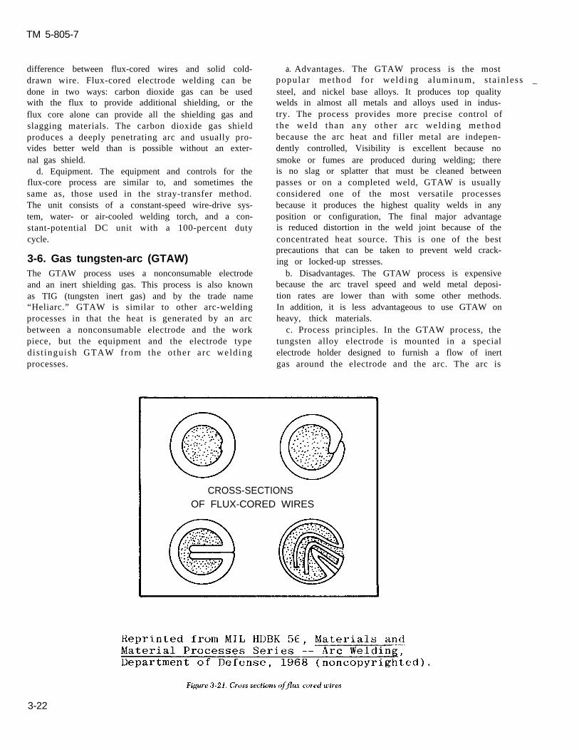
c. Process principles. The flux-core welding wire,or electrode, is a hollow tube filled with a mixture ofdeoxidizers, fluxing agents, metal powders, andferro alloys, as shown in figure 3-21. The closureseam, which appears as a fine line, is the only visible
I 2 3 4 5 6
3-21
TM 5-805-7
difference between flux-cored wires and solid cold-drawn wire. Flux-cored electrode welding can bedone in two ways: carbon dioxide gas can be usedwith the flux to provide additional shielding, or theflux core alone can provide all the shielding gas andslagging materials. The carbon dioxide gas shieldproduces a deeply penetrating arc and usually pro-vides better weld than is possible without an exter-nal gas shield.
d. Equipment. The equipment and controls for theflux-core process are similar to, and sometimes thesame as, those used in the stray-transfer method.The unit consists of a constant-speed wire-drive sys-tem, water- or air-cooled welding torch, and a con-stant-potential DC unit with a 100-percent dutycycle.
3-6. Gas tungsten-arc (GTAW)The GTAW process uses a nonconsumable electrodeand an inert shielding gas. This process is also knownas TIG (tungsten inert gas) and by the trade name“Heliarc.” GTAW is similar to other arc-weldingprocesses in that the heat is generated by an arcbetween a nonconsumable electrode and the workpiece, but the equipment and the electrode typedis t inguish GTAW from the other arc weldingprocesses.
a. Advantages. The GTAW process is the mostpopular method for welding a luminum, s ta in less _steel, and nickel base alloys. It produces top qualitywelds in almost all metals and alloys used in indus-try. The process provides more precise control ofthe weld than any other arc welding methodbecause the arc heat and filler metal are indepen-dently controlled, Visibility is excellent because nosmoke or fumes are produced during welding; thereis no slag or splatter that must be cleaned betweenpasses or on a completed weld, GTAW is usuallyconsidered one of the most versatile processesbecause it produces the highest quality welds in anyposition or configuration, The final major advantageis reduced distortion in the weld joint because of theconcentrated heat source. This is one of the bestprecautions that can be taken to prevent weld crack-ing or locked-up stresses.
b. Disadvantages. The GTAW process is expensivebecause the arc travel speed and weld metal deposi-tion rates are lower than with some other methods.In addition, it is less advantageous to use GTAW onheavy, thick materials.
c. Process principles. In the GTAW process, thetungsten alloy electrode is mounted in a specialelectrode holder designed to furnish a flow of inertgas around the electrode and the arc. The arc is
CROSS-SECTIONSOF FLUX-CORED WIRES
3-22

T M 5 - 8 0 5 - 7
struck between the base metal and the electrode byone of two methods. In the first, called a scratchstart, the operator actually touches the work piecewith the tungsten and withdraws slightly. The sec-ond method uses high-frequency discharge from theelectrode to the work piece to establish the arc. Thisis better for welds that have to be very clean; ascratch start could leave particles of tungsten in theweld, causing brittle spots. After the arc is started,the filler metal, if required, is fed into the weld poolnear the arc, as shown in figure 3-22. The moltenweld metal, the adjacent base metal, and the elec-trodes are protected by a flowing gaseous envelopeof inert gas: generally argon, helium, or a mixture ofthe two. Most GTAW is done manually, but for pro-duction or assembly type welds such as long buttwelds, the system can be entirely automated. AC isused generally for aluminum and magnesium, whileDC straight polarity is used for all other metals.
d. Equipment. The equipment includes an electri-cal power source, electrode holder (torch), tungstenor tungsten alloy electrodes, gas flow regulatingequipment, and usually a remote rheostat for off-onswitching and current control (fig 3-22).
(1) There are AC and DC power units withbuilt-in high frequency generators designed specifi-cally for GTAW. These automatically control gasand water flow when welding begins and ends. How-ever, power supplies without these controls can alsobe used.
(2) If the electrode holder (torch) is water-cooled, a supply of cooling water is needed. Elec-trode holders are made so that electrodes and gasnozzles can be readily changed, either for differentsizes or for replacement.
(3) Mechanized GTAW equipment may includeelectronic devices for checking and adjusting thewelding torch level, equipment for work handling,provisions for initiating the arc and controlling gasand water flow, and filler metal feed mechanisms.
3-7. Submerged arc (SAW)In the SAW process, the arc is not visible, but issubmerged under a layer of granulated flux (fig 3-23). This process can be used with either a singleelectrode wire or many. AWS D1.1 describes theprocedure, equipment, electrodes, and flux usedwith SAW.
a. Advantages. SAW is an efficient process thatcan be used on nearly all ferrous metals. Welds ofvery good quality are produced in a wide range ofmetals thicker than 1/1 6 inch. Carbon, alloy, orstainless steels up to l/2-inch thick are welded inone pass, while thicker materials require morepasses. Weld metal deposition rates, arc travel
speeds, and weld completion rates are better thanthose for other processes. There is no visible arc andno weld spatter, and the deep penetrating effect ofconcentrated heat allows narrow welding grooves.Thus, it takes less filler metal to make a joint withSAW than with other welding processes , Theunfused flux can be recovered and recycled whenthe welding is finished.
b. Disadvantages. The basic limitation of SAW isthat it can only be used in the flat position and forhorizontal fillet welds. Welds can be made in thehorizontal position, but since the granular fluxneeded to shield the weld metal must be in place infront of the electrode, complicated dams and sup-ports may be required to contain the flux. Theequipment used in this process can be hand-held,but is usually mechanized, making it heavy and cum-bersome and thereby limiting its use to fabricationshops. The fused flux must be removed by chippingand wire brushing.
c. Process principles. SAW takes place beneaththe flux covering without sparks, spatter, smoke, orflash. The electrode and weld pool are completelycovered at all times during welding. The flux makespossible these special operating conditions, whichdistinguish SAW from other processes. When cold,the flux does not conduct electricity; therefore, thewelder must establish a conductive path for startingthe arc. This can be done by scratch starting wherethe electrode touches the base plate or by buryingsome steel wool in the flux at the starting point. Inthe molten state, the flux becomes highly conduc-tive. Once the arc is started, the heat produced bythe current causes the surrounding flux to becomemolten. This forms a conductive path, which is keptmolten by the continued flow of welding current.The buried part of the flux is melted; the visible partremains unchanged in both appearance and proper-ties, and can be reused. All currents and polaritiesare used, depending on the desired penetration andbead shape, Reverse polarity provides the best beadshape and penetration, while straight polarity giveshigher deposition rates but less penetration. Alter-nat ing current provides penet ra t ion somewherebetween the two and is preferred for multi-wirewelding. The fused flux is chipped off the weld anddiscarded.
(1) The welding electrodes must be positionedproperly. Flux is fed in front of and around the elec-trode by a hopper. The arc is struck and the elec-trodes moved along the weld. The operator watchesthe ammeter and voltmeter readings to control cur-rent and voltage adjustments. A variable-speedmotor controls the electrode feed; a power-operated
3-23

TM 5-805-7
3-24

carriage controls the travel rate. Unused flux is fedback into the hopper.
(2) Moderately thick sections of material (up to1 inch) with a carbon content up to 0.35 percent canbe welded without precautions such as preheatingand postweld heat treatment. Preheating is gener-ally needed when the carbon content is over 0.35percent.
(3) Low-alloy steels maybe welded if the weld.area is preheated to slow the rate of cooling. Thismust be done to avoid cracking in the weld and heat-affected zone.
(4) When certain quenched and tempered struc-tural steels (ASTM A 514 and A 517) are welded,the heat input must be closely controlled to makesure strength and notch toughness are retained inthe heat-affected zone. To keep a high level ofstrength and notch toughness, heat must dissipate
rapidly so that desirable microstructure form. Any-thing that delays cooling, such as preheating or highwelding heat inputs, should be avoided.
d. Equipment. Both semi-automatic and automaticSAW equipment is available; the type used generallydepends on the work to be done, and on economicfactors. Semi-automatic equipment is better forrepair welding and for welding that cannot be doneautomatically because of the geometry of the part.Figure 3-24 shows the equipment needed for auto-matic SAW; included are a power source, wire feed-ing system, flux feeding system, and a welding torch.
(1) The power supply may be DC constant cur-rent, DC constant voltage, or AC. The power supplyand wire-drive mechanism must be designed tooperate together so that the arc length can be con-trolled effectively. SAW generally is done at highercurrents (500 to 1000 amperes) than other types ofarc welding, so the power supply must have a highcurrent rating at high duty cycles.
3-25

T M 5 - 8 0 5 - 7
(2) The electrodes used with SAW are generallybare rods or wire in coils. The choice of electrodedepends on the way the alloying elements are intro-duced into the weld. One method is to use mild-steel electrodes with fluxes containing the alloy.Another method often used requires special alloysteel electrodes and neutral flux, and includes low-carbon steel, low-carbon alloy steel, special alloysteels, high-carbon steels, stainless steels, and non-ferrous alloys.
(3) The fluxes are granulated, fusible mineralmaterials of various compositions and particle sizes.The choice of flux depends on the welding proce-dure, joint configuration, and composition of thebase metal to be welded. The flux may includealloying elements.
3-8. Exothermic weldingIn exothermic welding, heat is generated by thechemical reaction between a combination of alumi-num and iron oxide. This mixture is placed in a hop-per above a mold which surrounds the joint, and isthen ignited. A chemical reaction occurs, and themolten metal and slag drop through the hopper.Since the molten metal is heavier than the slag, itsettles to the bottom of the mold and touches the
3-26
steel joint. The molten metal melts the surface of themetal and fuses with it, forming the weld. This pro-cess, commonly referred to as “thermit welding, ” isused for joining reinforcing rods, rails, large castingsor forgings, and for repairing large structural shapes.Historically, thermit welding was largely confined tostructures made of iron and steel. But recently, thesubstitution of a copper oxide for iron oxide has ledto many applications within the electrical industry
such as joining or repairing electrical connectors,cables, bus bars, and bus tubes. Thermit welding isalso used for welding pipe. In this application thethermi t does not mix with the pipe metal, butmerely furnishes the heat to melt the pipe ends,which are then butted together as they melt.
a. Advantages.(1) The welder needs very little instruction or
experience to produce good welds rapidly.(2) Large sections may be fusion welded, and
large quantities of filler metal may be depositedquickly. Thermit welding can be roughly comparedto a foundry casting operation. The one difference isthat the metal being poured is considerably hotterthan when melted in a furnace. The completed weldleft in the mold cools slowly, reducing residual stress.

T M 5 - 8 0 5 - 7
b. Disadvantages. Molds are needed to hold themolten metal around the weld joint. For one-of-a-kind jobs, such as repairs, the molds must be con-structed individually, and a suitable wax or plasticform filler materials must be inserted in the gap toinsure proper clearance between the parts.Preformed permanent molds are used for repetitivejobs — welding rails or reinforcing rods, forexample.
c. Process principles. Thermit welding is based onthe fundamental principle that aluminum is morechemically active than iron. The welding processconsists of mixing the iron oxide and aluminum, bothin powder form, and placing them in a hopper orcrucible above a mold which surrounds the jointarea. (The joint to be welded must be cleaned, prop-erly spaced, and preheated. ) An ignition powder,such as a mixture of barium peroxide and aluminumpowder, is placed on top of the thermit, and a fuse isinserted into the powder. The reaction starts after
the fuse ignites the mixture; this happens at about2000 “F. The reaction is nonexplosive and takesabout 30 seconds; once the mixture starts to burn, itis self-propagating. When the reaction is complete,the molten metal has reached a temperature ofa p p r o x i m a t e l y 4 5 0 0 oF, which is nearly 1 6 0 0 oFhigher than the temperature of ordinary moltensteel. The metal is poured into the mold to form theweld (fig 3-25). The mold is allowed to remain inposition for several hours to permit solidificationand to anneal the weld. The deposited metal coolsuniformly and is comparatively free from stresses.The mold is then removed and the gates and risersare cut away, Excess weld can be ground ormachined. Although the principal application ofthermit welding has been with the aluminum andiron oxide mixture on steel structures, other metalsor their oxides may be included in the thermit mix-ture. Chromium, nickel, manganese, tungsten, tita-nium, molybdenum, and cobalt can be used. These
3-27

T M 5 - 8 0 5 - 7
elements alloy with iron and are used when higherstrength, ductility, or hardness is required. Theyalso permit control of the temperature and time ofthe reaction. Cast iron can be welded with a specialthermit mixture.
d. Equipment. Thermit welding kits are available.They consist of a permanent mold, prepackagedthermit charges, consumable tapping discs, chargesof ignition powder, and fuses. An individually con-structed mold requires wax or foam filler, sand mold(a special mixture of silica sand and plastic clay), andgates, risers, pouring gates, and a slag basin (fig 3-25).
3-9. Arc-stud weldingArc-stud welding is an arc welding process in whichan electric arc is struck between a metal stud andanother piece of metal. When the surfaces to be
jointed are proper ly heated, they are broughttogether under pressure. A ceramic ferrule sur-rounding the stud can provide partial shielding. The process is generally referred to as “stud welding. ”AWS D1.1 descr ibes s tud welding procedures ,equipment, workmanship, qual i ty control , andinspection requirements.
a. Advantages. Arc-stud welding has many advan-tages and uses. With this process, there is no need todrill or punch holes, nor to fasten an object mechan-ically to a main structure with bolts, rivets, orscrews. Arc-stud welding is widely accepted by allthe metal-working industries. Since virtually everyphase of the operation is automatic, no previouswelding experience is necessary. Inexperiencedoperators can be trained quickly, and once theequipment is set for a particular job, high-qualitywelds are quickly and easily made. The welding gun
b. Trigger is depressed
3-28

TM 5-805-7
CONTROL
3-29

TM 5-805-7
is light and easy to handle, making the equipmentvery portable.
b. Disadvantages. Since this is a versatile process,there are no real disadvantages; however, there aresome limitations on its use. Stud welding is approvedfor use on low-pressure heating boilers built underthe ASME Boiler and Pressure Vessel Code for allapplications except stay bolts. This includes coverplates, clean-out or access doors, and studded open-ings for boiler-tubing water-heater coils. Stud weld-ing is approved for use on nonpressure parts onpower boilers and unfired vessels.
c. Process principles. In the arc-stud welding pro-cess, the flux-coated stud is inserted into a collet orchuck which is an integral part of the gun. A porce-lain ferrule surrounds each stud to shield the arc,hold the molten pool in place, and help form anacceptable fillet shape. The flux on the end of thestud helps the operator control the arc and makestud welds in any position. The operator places thegun in the proper position, and spring pressure fromthe gun holds the stud against the work piece. Whenthe trigger is depressed, it completes an electric cir-cuit, causing the collet to withdraw the stud fromthe work piece a preset distance, creating a gap andan electric arc. At the end of an automatically timedinterval, the molten end of the stud is plunged intothe molten pool which has formed on the surface ofthe plate. The process is similar to conventionalmeta l l ic -arc welding because , in ef fec t , the s tudserves as a consumable e lec t rode whi le the currentis flowing. The molten metal quickly solidifies andthe collet releases the stud (fig 3-26). The operatorremoves the gun and is ready for the next weldingoperation, all within seconds. Stainless steel, magne-sium, and aluminum can be welded with basicallythe same equipment as that used for steel — exceptinert gas must be fed through the gun to protect theweld.
(2) Low-alloy steels may be satisfactorily stud,welded without preheating if the carbon content isheld to 0.15 percent maximum. To prevent cracking in the heat-affected zone, preheating is necessarywhen the carbon content exceeds 0.15 percent.
(3) The heat-treatable, high-strength, low-alloystructural steels require more attention since theyusually are hardenable enough to form martensite inthe heat-affected zone. These steels are quite sensi-tive to underbead cracking, and the weld area isusually low in ductility. Preheating to about 700°Fis recommended when steels of this category arestud welded.
d. Equipment. The equipment for stud weldingconsists of a DC power source; stud welding gun;welding cables; ferrules for shielding the arc; andcontrols, including timing devices. The equipment isusually portable, but stationary equipment for large-scale operations is used widely.
(1) The power source is a normal weldingmachine adapted for stud welding. The cables aremade the same way as standard welding cables. Thegun is designed to assure correct alignment and holdthe stud. This gun has a trigger to start current flowand a timing device that withdraws the stud at theproper time to create the arc, moves the stud intothe molten pool, and holds it until the molten poolsolidifies (fig 3-27).
(2) A ferrule is used with each stud. It shields ‘ - -
the arc, protects the welder, and eliminates the needfor a full face helmet. The ferrule concentrates heatduring welding and confines molten metal to theweld area. It helps prevent both oxidation of themolten metal during the arcing cycle and charring ofthe work piece.
(3) Studs are available in a variety of shapes,sizes, and diameters. Some are designed for thread-ing or riveting, others serve as nails. Studs are avail-able as straight and bent shapes, hooks, or eyebolts.
(1) In practice, the same restrictions apply bothto the metal-arc welding of carbon steels and to stud 3-10. Process selectionwelding. Carbon steels with a carbon content up to Table 3-2 is a selection guide for the welding pro-
0.30 percent may be welded without preheating. cesses discussed in this chapter. This table is based
When the carbon content exceeds 0.30 percent, on the particular applications encountered in field
particularly in heavy sections, preheating is advisa- welding.
ble to prevent cracking in the heat-affected zone. Insome cases, a combination of preheating and post-heating has proven helpful.
3-30

T M 5 - 8 0 5 - 7
Table 3-2. Summary of welding processes and application
Conditions
Materialscommonlywelded
3-31

TM 5-805-7
CHAPTER 4
WELDING OF STAINLESS STEEL
4-1. General
Stainless steels were originally developed because oftheir outstanding resistance to corrosion. They alsoexhibit good mechanical properties, which can be asimportant to the life of the structure as the corrosionresistance. There are four types of stainless steel:martensitic, ferritic, austenitic, and precipitationhardened. These steels exhibit a wide range ofmechanical properties both at room temperaturesand at cryogenic tempera tures (be low – 1 5 0degrees F). The stainless steels commonly used arecovered in specifications of ASTM, the AmericanIron and Steel Institute (AISI), the Society of Auto-motive Engineers (SAE), ASME, API, and the mili-tary or other Federal agencies. Commonly usedstainless steels are the austenitic class that meetspecifications for AISI grades in the 200 and 300series. Martensitic stainless steels in the AISI 400series are also used. When designing for 400 seriesstainless steels, one must use extra care because oftheir sensitivity in heat treating. Stainless steels thatconform to other specifications can be used whereparticular requirements must be met. Stainless steelwelding electrodes are specified by AWS or militarydocuments. Commonly used welding electrodes forfabrication meet specifications AWS A5.4, A5.9,A5.11, A5.14, and A5.22.
4-2. Weldability of stainless steels
The austenitic chromium-nickel steels are oftenused for cryogenic and vacuum systems. These steelsare characterized by their corrosion resistance, low-magnetic permeability, good high- temperaturestrength, and excellent low-temperature ductilityand notch toughness. Some of the austenitic steels,however, do have characteristics that restrict theiruse in cryogenic applications (table 4-1). But theaustenitic steels are considered the most weldable ofthe high alloy steels. Three basic factors affect theweldability of stainless steels: (1) the chemical com-position of the base metal and the weld metal, (2)the microstructure of the base metal and the weldmetal, and (3) the use of the correct welding proce-dures and techniques
a. Chemical composition. The major constituentsin stainless steels are iron, carbon, manganese,
silicon, chromium, and nickel. The chromium is pri-marily responsible for the stain and corrosion resis-tance of these steels. It has an affinity for oxygen andforms a thin, impervious, protective, oxide layer.Chromium also has an affinity for carbon and formschromium-carbides rapidly between 8 0 0 a n d1600°F.
(1) When chromium-carbides are formed, theytie up much of the chromium and severely reducethe corrosion resistance of the steel. Typically, thiscan happen in a zone next to and on either side ofthe weld joint. This phenomenon, known as sensiti-zation, occurs because a region next to the weld isheated to between 800 and 1600 “F by the weldingarc. If the weld joint is subjected to a corrosiveenvironment, knife-line attack results. Three tech-niques are used to mitigate sensitization. Thesemethods can be expensive and should be used onlywhen sensitization is a problem.
(a) Extra-low carbon (less than 0.03 percentcarbon) grades of steel can be used. This carboncontent is the maximum amount that is soluble instainless steels and does not easily come out ofsolution.
(b) Stabilizing elements such as columbiumand tantalum can be used. These form carbides pref-erentially over chromium, thereby tying up thecarbon.
(c) A post-weld heat treatment can be used.The most common heat treatment technique is tosolution anneal at 1900°F, then water quench. Thistechnique puts all the carbon in solution and keeps itthere by rapidly cooling through the 1600 to 800oFrange.
(2) In a fully austenitic stainless steel weld (suchas a type 310), the ductility and soundness of theweld depend on the carbon to silicon ratio. Ideally,this ratio should be about 1:2. An increase in siliconabove this ratio causes fissuring (microcracking) inthe weld metal and a rapid loss of ductility. Anincrease in the carbon ratio causes a less severedecrease in ductility without affecting weld sound-ness. With fully austenitic stainless steels, the car-bon to silicon ratio must be closely controlled. Thistends to limit the use of such steels when weld jointswith the best quality and ductility are required.
b. Microstructural effects. Two microstructuralfactors affect the quality of austenitic stainless steel
4-1

T M 5 - 8 0 5 - 7
weld joints: ferrite content in weld metal and basemetal, and grain growth in weld metal and the heat-affected zone. The following discussion describesmethods of controlling these factors. Designers canuse this information to specify the proper base mate-rials, and welding procedures and materials.
(1) Ferrite content.(a) Fully austenitic weld joints often tend to
develop microcracks and fissures during welding. Toprevent this, designers should select filler metals orelectrodes that will form an austenitic weld depositcontaining a small percentage of ferrite. Such weldsare highly resistant to cracking. However, if the fer-rite content becomes too high in cryogenic applica-tions, the weld metal’s impact strength at servicetemperatures can be seriously reduced. For theseapplications. the ferrite content of the weld metalshould be within the range of 4 to 10 percent.
(b) The actual ferrite content depends on thecompositions of the base metal and filler metal orelectrode, and the extent to which the weld metaldeposit is diluted by the welded parent metal. ASchaeffler diagram (fig 4-1) can help designers esti-mate both the percentage of ferrite in the welddeposit and the filler metal composition necessary toform the required ferrite in the weld metal. Thisdiagram is used to predict the amount of ferrite instainless steel weld metal on the basis of weld metalcomposition. The diagram shows how the micro-structure of the weld deposit is affected by the alloyelements in stainless steel that act like nickel, andthose that act like chromium. The nickel equivalentgroup which is the austenite former includes nickel,- -carbon, and manganese; an allowance is also madefor the nitrogen content. The chromium equivalentgroup which is the ferrite former includes chro-mium, molybdenum, silicon, and columbium. Thenickel equivalent is the ordinate of the diagram, andthe chromium is the abscissa.
(c) To estimate the microstructure of the weldmetal, the designer uses the following formulas tocalculate the nickel and chromium equivalents:
nickel equivalent = % nickel + 30 X %carbon + 0.5 X %manganese
chromium equiva lent = 70 chromium + %molybdenum + 1.5X % silicon + 0.5X % columbium.
The nickel and chromium equivalents are calculatedfor both the base and weld metal . The valuesobtained are then plotted on the Schaeffler diagram,and a line is drawn between the two points to indi-cate the possible ferrite percentages that could be in
the weld metal because of base metal dilution. Forexample, if type 302 stainless steel is welded usingtype 308 electrode, then the nickel equivalent for the 302 stainless is 12, and the chromium equivalentis 18.25. When this point is plotted, it is totally inthe austenitic region, so there will be no ferrite. Thetype 308 electrode will have a nickel equivalent of12, and a chromium equivalent of 21, thus putting itclose to the 10 percent ferrite line.
(d) The Schaeffler diagram can predict notonly the amount of ferrite in the microstructure, butalso the electrode composition that will preventexcessive ferrite or martensite content in stainlesssteel weld metal. In addition, the diagram is helpfulin estimating the trend of the microstructure devel-oped when dissimilar steels are welded. If pieces ofcarbon steel and stainless steel are to be weldedtogether, the compositions of the two can be markedon the diagram; the tie line drawn between themindicates t h e m i c r o s t r u c t u r e that may beencountered.
(2) Grain growth. The toughness and ductility ofthe heat-affected zone and the weld metal may bereduced somewhat because of grain growth causedby the welding heat. However, unless extremelyhigh welding heats are used or very heavy weldpasses are deposited, the problem of decreasedtoughness and ductility resulting from grain growthis not serious. If impact testing of sample weld joints indicates that the notch toughness of the weld metalor heat-affected zone has suffered, the welding pro-cess should be modified to decrease the heat inputto the joint and thus restrict the amount of graingrowth.
c . Preweld and postweld heat t rea t ing. Weldjoints in stainless steel are neither preheated norpostheated. These techniques make the joints coolslowly and could cause sensitization, with a resultingloss of notch toughness. However, rapid coolingafter welding prevents sensitization of the weldmetal and heat-affected zone. In multipass welds,the maximum in terpass tempera ture should be300 “F. Stress relieving of austenitic stainless steelweld joints also should be avoided because it seldomworks and sensitization can occur easily.
d. Weld cracking.(1) Weld cracking in austenitic stainless steels
can be divided into four types: crater cracks, starcracks, hot cracks or microfissures, and root cracks.All four types of cracking are believed to be mani-festations of the same basic kind of cracking —namely hot cracking, or in its earliest stage, microfis-suring. Hot cracking presented many difficultiessome years ago, but now it can be prevented in
4-2

TM 5-805-7
weldments. Hot cracks occur intergranularly; appar-ently, the segregation of low melting constituents inthe grain boundaries induces fissuring susceptibility.
(a) The formation of microfissures seems todepend on five factors: the microstructure of theweld metal; the composition of the weld metal, par-ticularly the level of residual elements; the amountof stress imposed on the weld as it cools through thehigh temperature range; the ductility of the weldmetal at high temperatures; and the presence ofnotches that form incipient cracks at the edge of theweld.
(b) For many years,. it was believed thatmicrofissures only developed in the as-depositedweld metal shortly after solidification. However,more recent work has clearly shown that microfis-sures can occur in the heat-affected zones of previ-ously deposited sound weld beads.
(2) The micros t ruc ture of the weld meta lstrongly affects microfissuring susceptibility. Weldmetal having a wholly austenitic micro-structure is alo t more sens i t ive to condi t ions tha t promotemicrofissuring than weld metal containing somedelta or free ferrite in the austenitic matrix. As dis-cussed in a above, the chemical composition —— bothal loy content and res idual e lement content —strongly influences rnicrofissuring susceptibility ofthe wholly austenitic stainless steel weld metals.Microfissuring is reduced by a small increase in car-bon content, a substantial increase in manganese, oran increase in the nitrogen content. The residualelements that influence cracking most often areboron, phosphorus, sulfur, selenium, silicon, colum-bium, and tantalum.
(3) In welding austenitic stainless steels, two dif-ferent practices are now used, depending on themicrostructure expected in the weld metal.
(a) Whenever possible, ferrite-containing aus-tenitic weld structure is used. The filler metal mustbe selected carefully and the welding procedureplanned in detail to secure the small, but important,amount of delta ferrite. The Schaeffler diagram, dis-cussed in b above, has been used frequently fordetermining whether a specified weld compositionwill contain enough ferrite.
(b) When a wholly austenitic weld structuremust be used, welding materials containing the low-est possible amount of recognized crack promotersshould be selected. In addition, the amount of alloyelements known to improve crack resistance shouldbe increased. Even with the best materials and themost favorable welding procedure, wholly austeniticdeposits are more crack sensitive than the ferrite-containing types. Therefore, all phases of weldingand inspection need greater care.
(4) Base metal heat-affected zone cracking inwelded austenitic stainless steels can be a problemin heavier sections (more than 1-inch thick). Suchcracking can have two causes. One is an intergranu-lar form of hot shortness in a heat-affected zoneduring welding. The weld metal cracks because ofgrain boundary liquation or embrittlement at or nearwelding temperatures. The other cause for crackingis a complex phenomenon involving strain-inducedprecipitation in the heat-affected zone during post-weld heat treatments or service at high tempera-tures (above 450 oF). A change in mechanicalproperties thus results in stress-rupture failureunder certain conditions. In this form of failure, thekey to the problem is the precipitation of colum-bium carbides in the stressed heat-affected zones. Aslittle as 0.1 percent columbium as a residual elementcan produce strain-induced precipitation and causewelded heavy sections to fail by cracking during ser-vice at high temperatures. A t i tan ium-s tabi l izedstainless steel, such as type 347, can be used to helpkeep a nonstabilized stainless steel from cracking.
e. Other weld defects. Defects besides crackingoccur in the weld metal if an incorrect weld processor technique is used. These defects include porosity,slag inclusions, incomplete fusion, inadequate jointpenetration, and undercutting.
(1) Porosity is a cavity-type discontinuityformed by gas entrapped during solidification. Thegases that form porosity are either driven from solu-tion in the weld metal because of low volubility atlower temperatures, or are produced by chemicalreactions in the molten weld pool. These gases aretrapped in the weld metal because solidificationoccurs before the gases have time to rise to the sur-face of the pool. Porosity will form less often if veryhigh currents or long arc lengths are avoided. Thewelding contractor must make sure these variablesare taken into account when the procedure is devel-oped and the welder qualification tests are con-ducted. This i s especia l ly t rue for the SMAWprocess because high currents and long arc lengthsconsume large amounts of deoxidants in the elec-trode covering, leaving little to combine with theexcess gases in the weld pool. Moreover, the typeand distribution of porosity will give some indica-tions of its cause. The types of porosity arc classifiedin the acceptance standards of the various codes(ASME, API, or AWS, as applicable). Generally, thetypes of porosity depend on the distance betweenindividual pores or groups of pores.
(a) Uniforrnly scattered porosity can be foundin many weldments and is of little concern becausethere is usually enough sound metal between thepores.
4-4

TM 5-805-7
(b) Clustered porosity is often associated withchanges in arc conditions. For instance, areas wherethe arc has been started or stopped frequently con-tain cluster porosity.
(c) Linear porosity is usually found in the rootpass and is considered a special case of inadequatejoint penetration.
(2) Slag inclusions are oxides or nonmetallicsolids that become trapped in solidifying metal. Theinclusions either can be completely surrounded byweld metal or can be between the weld metal andthe base plate. In the SMAW process, chemical reac-tions between the weld metal and the coating mate-r ia ls produce a nonmeta l l ic s lag tha t has lowvolubility in the weld metal and generally will floatto the surface. Sometimes, the slag is forced into theweld metal by the stirring action of the arc, or flowsahead of the arc and is covered by the weld metal.Proper cleaning and preparation of the weld joint orproper manipulation of the electrode will reduce thenumber of slag inclusions. The welding contractorcan make sure these precautions are included whenwelding procedures are developed and welder quali-fication tests are conducted.
(3) Incomplete fusion occurs when two weldbeads, or the base metal and a weld bead, have notfused together. This is caused by failure to raise theadjoining material to the fusion temperature or fail-ure to dissolve any oxides or other foreign materialon the surface to which the new weld bead mustfuse. Incomplete fusion can be prevented by follow-ing the approved welding procedure, which shouldinclude cleaning of the preceding bead and contigu-ous base metal in the weld joint. Particular careshould be used in welding stainless steel because thehigh temperature increases the amount of chromiumoxide formed and the steel becomes hard to weldwith the increased oxide layer.
(4) Inadequate joint penetration occurs whenthe fusion of the weld and the base metal at the rootof the joint is less than specified by design. Poorpenetration affects weld joints that will be stressedin service; the root forms a notch that acts as a stressconcentrator, which leads to early failure of thejoint. Although a poorly cleaned joint may causeinadequate penetration, poor heat transfer condi-tions in the joint are more often at fault. Heat trans-fer can be increased by using wider angles for V-grooves or a larger root opening.
(5) Undercutting refers to either a sharp recessin the side wall of a weld joint or reduced thicknessof the base plate at the toe of the last weld bead on
high voltages, as well as low current and fast travel
speeds, may increase the tendency to undercut. Ifundercutting is a sharp recess in the joint side wall,it should be smoothed out by grinding or chippingbefore the next weld bead is placed. AWS specifica-tions and the ASME Boiler and Pressure Vessel Codeimpose limitations on undercutting.
4-3. Joint designWeld joints are prepared either by plasma-arc cut-ting or by machining or grinding, depending on thealloy. Before welding, the joint surfaces must becleaned of all foreign material, such as paint, dirt,scale, or oxides. Cleaning may be done with suitablesolvents (e. g., acetone or alcohol) or light grinding.Care should be taken to avoid nicking or gougingthe joint surface since such flaws can interfere withthe welding operation.
4-4. Methods of welding stainless steelsStainless steels are readily weldable in the field bySMAW, GMAW, FCAW, and SAW processes.GTAW can be used for field fabrication, but it is aslow process. SMAW is used most often because theequipment is portable and easy to use. GMAW,FCAW, and SAW are being used more often in thefield because they are economical and produce high-quality welds. Manufacturers’ recommendations forwelding stainless steel should be followed. Theseinclude recommendations on joint designs, preheattemperatures, any associated post-weld heat treat-ment, and shielding gas.
4-5. Shielded metal-arc (SMAW)SMAW has been the preferred method of weldingbecause of its versatility, simplicity of equipment,and wide selection of electrodes available — all ofwhich are important for field welding applications.AWS A5.4 is the specification for stainless steelSMAW electrodes.
a. Electrode classification system. The SMAWelectrode classification code contains an E and threenumbers, followed by a dash and either a 15 or 16(EXXX-15), The E designates that the material is anelectrode, and the three digits indicate composition.Sometimes there are letters following the three dig-its; these letters indicate a modification of the stan-dard composition. The 15 or 16 specify the type ofcurrent with which these electrodes may be used.Both designations indicate that the electrode is usa-ble in all positions: flat, horizontal, overhead, andvertical.
(1) The 15 indicates that the covering of this
electrodes are usable with DC reverse-polarity only.
4-5

TM 5-805-7
(2) The designation 16 indicates electrodes thathave a lime- or titania-type covering with a largeproportion of titanium-bearing minerals. The cover-ings of these electrodes also contain readily ionizingelements — such as potassium — to stabilize the arcfor AC welding.
b. Chemical requirements. The SMAW electroderequirements for the nickel-chromium austeniticstainless steels are included in AWS A5.4. Thechemical requirements are based on the as-depos-ited weld metal chemistry. Chemical requirementsdo not change when a 15 or 16 electrode is used.
c. Weld metal mechanical properties. The AWSrequires the deposited weld metal to have a mini-mum tensile strength of 60,000 to 100,000 psi, withminimum elongations of 20 to 35 percent. Thedetailed requirements are in AWS A5.4.
d. Recommended filler metals for austenitic stain-less steels. The Welding Handbook, section 4, “Met-als and Their Weldability, ” chapter 64, “The 4-10Percent Chromium-Molybdenum Steels and theStraight Chromium Stainless Steels, ” has a table giv-ing a complete list of base metals by AISI numberand recommended filler metals to join the base met-als. This table lists not only the chromium stainlesssteels, but also heat-resisting stainless steels and allthe austenitic stainless steels. If the type of stainlesssteel is not listed, then manufacturers’ recommenda-tions should be followed. An appendix to AWS A5.4describes the intended uses of the electrodes.
4-6. Gas metal-arc (GMAW)
GMAW is being used more often for shop and fieldApplications because it offers much less downtimefor electrode changes, less loss resulting from stubends and spatter, and minimal interpass cleaningcompared to the SMAW process. GMAW can bedone in all positions by using either short-circuitingtransfer or a pulsed voltage power supply. GMAWhas slightly less versatility than SMAW because thewelding gun is bulkier than the electrode holder forthe SMAW; furthermore, the equipment is morecomplex and expensive, and requires somewhatmore skill by the operator,
a. Electrode classification system. The classifica-tion code for GMAW electrode wire consists of an E,an R, and three digits: ERXXX. The letter E indi-cates that this is an electrode material, and the Rindicates that it is a welding rod. Since these fillermetals are used for the atomic hydrogen and GTAWmethod as well as for SAW and GMAW, both lettersare used. The three-digit number, such as 308 inER308, designates the chemical composition of thefiller metal. An “Si” after the classification indicates
that the rod or electrode contains between 0.5 and 1percent silicon rather than the standard 0.25 to 0.60percent silicon. An “L” indicates that this electrodehas a carbon content not exceeding 0.03 percent.The specifications for these electrodes are containedin AWS A5.9.
b. Chemical requirements. The chemical require-ments for the GMAW electrodes are in AWS A5.9.The proportions of elements are similar in elec-trodes and base metal with the same designation. Allchemical analyses are based on the as-manufacturedelectrode wire.
c. Weld metal mechanical properties. The all-weldmetal tensile properties for the chromium-nickelaustenitic stainless steel electrodes are presented inthe appendix of AWS A5.9. These mechanicalproperties are the same as those required for theSMAW electrodes.
d. Shielding gas. Two types of shield gas are usedwith the GMAW process: pure argon and argon plus2 percent oxygen. The minimum thickness whichcan be welded using this process is about 1/8 to 3/16inch.
e. Recommended filler metals for chromium-nickel stainless steels. The austenitic stainless steelsare listed by AISI specification numbers in the table“Covered Elect rodes Recommended for WeldsBetween Stainless and Heat-Resisting Steels” in theWelding Handbook, section 4, chapter 64. If steelsother than those listed are used, then the manufac-turer’s recommendation for weld metals and preheattemperatures should be followed. An appendix toAWS A5.9 describes the intended uses of the elec-trode types.
4-7, Flux-cored arc welding (FCAW)
FCAW uses equipment similar to that of GMAW,and offers the advantages of high deposition andfluxing ingredients. This process is used primarily inthe flat and horizontal positions, but can be used inother positions if the proper electrode diameter andwelding currents are selected. Flux-cored, corro-sion-resisting chromium and chromium-nickel steelelectrodes are specified by AWS A5.22.
a. Electrode classification system. The FCAWelectrodes are classified similarly to the GMAWelectrodes. In the code EXXXT-Y, the EXXX desig-nation is the same as for the GMAW electrodes andcan be any of the material classification numberspreviously noted. The letter T indicates a continu-ous tubular electrode with a powdered flux withinthe tube. The suffix Y can be any number from 1 to 3or the letter G. The numbers indicate the externalshielding medium to be used during welding. A “ 1”
4-6

designates an electrode using carbon dioxide shield-ing gas. A “ 2“ designates an electrode using a mix-
ture of argon plus 2 percent oxygen. A “3”designates an electrode using no external shieldinggas because the shielding is provided by the corematerial. The “G” indicates an electrode with anunspecified method of shielding; no requirementsare imposed on it.
b. Chemical requirements. A table in AWS A5.22presents the deposited weld metal’s chemical analy-s i s for aus teni t ic chromium-nickel s ta in less s tee lFCAW electrodes. All classifications of the FCAWelectrodes have chemical requirements except the Gclassification, and those requirements are only asagreed on between the supplier and the purchaser.
c . Weld meta l mechanical proper t ies . Theall–weld metal tensile requirements for the austen-itic chromium-nickel stainless steel FCAW elec-trodes are presented in a table in AWS A5.22. Thetensile strength minimums vary from 60,000 to80,000 psi, with a minimum elongation between 20and 35 percent. The G classification of the elec-trodes does not have any requirements except thosethe supplier and purchaser agree on.
d. Shielding gas. The FCAW electrodes can usethree types of shielding: carbon dioxide, argon plus2 percent oxygen, or inner shield. The inner shieldmethod uses gas-producing materials within the coreof the electrode. The shielding gas for the G desig-nation electrode is not specified.
e. Recommended filler metals for austenitic chro-mium-nickel stainless steeIs. The recommended fil-ler metal/base metal combinations for the AISI-designated stainless steels are in a table in the Weld-ing Handbook, section 4, chapter 64. If stainlesssteels other than those listed are to be used, thenmanufacturers’ recommendations for weld metalshould be followed. An appendix to AWS A5.22 forFCAW electrodes lists the intended uses of theelectrodes.
4-8. Submerged arc (SAW)
The SAW process is limited to flat position and hori-zontal fillet welds because a granulated flux is usedto protect the arc and the molten weld metal. SAWelectrodes are specified by AWS A5.9. This is thesame specification for the GMAW electrodes. ForSAW, DC reverse polarity or AC may be used. Basicfluxes are generally recommended to minimizesilicon pickup and the oxidation of chromium andother elements. In general, electrodes having asilicon content of 0.6 percent or less are desirablefor submerged arc welding since the fluxes usually
result in some silicon pickup. The material classifica-tion, chemical requirements, and mechanical prop-erty requirements are the same as those for theGMAW electrodes in the as-welded condition. Therecommended filler metals for the austenitic chro-mium-nickel stainless steel are the same as those forthe GMAW electrode and are listed in the table inthe Welding Handbook, section 4, chapter 64, asnoted in the above discussion of the recommendedfiller metals for other processes.
4-9. Special considerations in weldingstainless steels
a. Effects of thermal properties of stainless steelon welding conditions and distortion. The thermalproperties (coefficients of thermal conductivity andexpansion, and melting point) of stainless steel differsomewhat from those of carbon steels. The differ-ences affect the welding operations, and steps mustbe taken to compensate for the effects of these ther-mal properties. These steps are discussed in para-graph 7-5.
b. Welding characteristics.(1) Generally, austenitic stainless steel can be
welded with about 20 percent less heat input thancarbon steels. There are several reasons for this.Stainless steels have a higher electrical resistivitythan do carbon steels. As a result, stainless steels gethotter than carbon steels when the same weldingcurrent is used. Thus, a given amount of stainlesssteel can be melted with less current than the sameamount of carbon steel. In addition, less heat or cur-rent is needed to melt austenitic stainless steelsbecause they have lower melting points than carbonsteel. Finally, the heat conductivity y of these stainlesssteels is lower than that of other steels. Therefore,the heat built up in the metal from the weldingoperation flows away from the weld at a slower rate.The result is that during welding, higher tempera-tures are reached in a shorter time.
(2) When welded, austenitic stainless steelstend to warp and buckle more than carbon steel.This is because the coefficient of thermal expansionof austenitic stainless steel is about 1-1/2 times aslarge as that of carbon steel. This problem is furtheraggravated by stainless steel’s lower thermal con-ductivity, which tends to concentrate welding heatin a smaller area. To keep warping and buckling to aminimum, jigs and fixtures, carefully selected weld-ing sequences, and accurate fitup generally have tobe used. Preheating to reduce distortion should beavoided when welding austenitic stainless steel sincethis could lead to sensitization of portions of theweld joint.
4-7

T M 5 - 8 0 5 - 7
(3) Special precautions are required if tack of the weld. It should be inspected to ensure that itwelding is used to control distortion and maintain is sound and does not contain tiny cracks or porosity,joint alignment. If these precautions are not taken, The surface of the tack weld should be ground to atack welds can be a source of weldmetal cracking, smooth, concave contour so that it will be com-porosity, incomplete penetration, or lack of fusion. pletely melted into the final weld.A tack weld must be of the same quality as the rest
Table 4-1. Austenitic stainless steels most commonly used for cryogenic and uacuurn environmcnt equipment
4--8

CHAPTER 5
WELDING CARBON STEEL AND LOW-ALLOY STEELS
5-1. GeneralThe steels commonly used in constructing buildings,bridges, and piping systems are covered in specifica-tions of ASTM, AISI, ASME, SAE, and APL Thesespecifications often refer to the same types of steels,although they put different restrictions on the chem-ical analysis and mechanical properties. Commonlyused materials for welded construction in buildingsand bridges meet specifications ASTM A 36, A 203,A 242, A 440, A 441, A 514, A 517, A 572, orA 588; and for piping systems, specifications ASTMA 53, A 106, A 134, A 139, A 671, A 672 or A 691or API 5L, 5LX, or 2H. Carbon or low-alloy steelswhich conform to any of many other specifications(including military and Federal) can be used whereparticular requirements must be met. Welding elec-trodes for steel are specified by MIL-E-22200. Com-monly used welding electrodes for constructionmeet specifications AWS A5.1, A5.5, A5.17, A5.18,and A5.20, and A5.23.
5-2. Weldability of carbon and low-alloysteelsThe AWS defines weldability as “the capacity of ametal to be welded under the fabrication conditionsimposed into a specific, suitably designed structureand to perform satisfactorily in the intended ser-vice” (AWS A3.0, p. 55). Given this definition, it isclear that many things affect the weldability of aspecific steel, including joint design, welding pro-cess, base metal chemistry, weld metal chemistry,mechanical properties, and impact properties. Gen-erally, steels specified for welded building andbridge construction and for piping systems are weld-able, with good mechanical properties obtained byproper attention to welding procedures and elec-trode selection. AWS D1.1 contains a selectionguide in the Technique section that matches elec-trode types with various ASTM and API steels. Man-ufacturers’ recommendations should be followed indeveloping welding procedures , including heattreatment and stress relief for high-strength/low-alloy steels conforming to ASTM A 514, A 517, orA 710.
a. Welding procedures The welding procedure touse is governed by the base plate, the structurebeing welded, the position of the weld (i.e., flat,
overhead, horizontal, or vertical), and the chemicalcomposition of the metal. Carbon levels in the basemetal govern the level of preheat temperature used.As a rule, the higher the carbon level, the higher thepreheat temperature used. Recommended preheatpractices are given in AWS D1.1. Improper weldingcan introduce into the weld joint defects such asporosity, slag inclusions, incomplete fusion, inade-quate joint penetration, undercutting, and cracking.Limitations on these various defects are governed byAWS D1.1, the ASME Boiler and Pressure VesselCode, or MIL-R-11468, where the acceptance leveldepends on the application.
b. Cracking. Cracking is one of the flaws thatoccurs most often in weldments. Cracks occur whenthe temperature of the cooling weld and base plateis within either of two ranges. One is at or slightlybelow the solidification temperature of the weldmetal, and the other is from about 4000 F to ambienttemperature. The high temperature cracking iscalled hot tearing and occurs because the metal isweak and has limited plasticity at this temperature.Fillet welds, weld craters, and the heat-affectedzone display this type of cracking. Low-temperaturecracking, or cold cracking, occurs in root passes ofbutt welds and in the heat-affected zone, and isinvariably associated with the presence of hydrogenas a dissolved impurity.
(1) Hot tearing. High-temperature cracks areintercrystalline tears that occur at or near the rangeof solidification for the metal. They are attributed tothe presence of low-freezing compounds such asiron sulfide, or solid impurities that have little or notensile strength or plasticity at high temperatures.These tears are in the metal that is last to freeze inthe weld deposit. Sulfur contributes significantly tohot tearing, while silicon, phosphorus, carbon, cop-per, and nickel have a lesser role. Manganese, on theother hand, has a beneficial effect on hot ductilitybecause it has a greater affinity to sulfur than irondoes. Manganese sulfides form; these have a highermelting temperature than steel and produce globu-lar inclusions rather than the intergranular film thatiron sulfide forms. If the ratio of manganese to sulfurin steel is 60 or greater, then hot tearing is not likelyto occur. Electrodes recommended by AWS D1.1 orthe ASME Boiler and Pressure Vessel Code, as
5-1

T M 5 - 8 0 5 - 7
appropriate, will produce a weld deposit with mini-mum hot cracking tendencies. Preheating, control-ling interpass temperature, and welding with as littlerestraint as possible are other ways to control hotcracking, particularly in a section thickness greaterthan 1/2 inch.
(2) Cold cracking.(a) Cold cracking occurs in the heat-affected
zone and weld metal . This may be caused bymechanical ef fec ts , a l loy content , or hydrogenpickup from moisture in the electrode flux or onsurfaces of the weld jo in t . Mechanical ly , h ighshrinkage stresses are induced in the weld metal bythe cooling weld and the restraining action of thebase metal. These stresses act in directions paralleland perpendicular to the weld and their magnitudemay be great enough to cause cracking.
(b) In any thickness of steel, cold crackingmay also occur ‘in the heat-affected zone because ofalloy content. This is called underbead cracking.The higher the alloy content, the greater the ten-dency. Susceptibility to underbead cracking maybeestimated from a steel’s “carbon equivalent, ” whichis determined from the formula:
As the C.E. increases, so does the susceptibility ofthe steel to cold cracking. As a steel’s alloy content,or C. E., increases, its capability to form a hardenedmicrostructure such as martensite when cooled rap-idly also increases. Certain areas of the weld joint,particularly those next to the base metal heat-affected zone, may cool rapidly enough to produce ahardened structure which becomes a “metallurgicalnotch. ” This hardened zone may be brittle, with acharacteristic low notch toughness. Increasing theheat input or the preheat/interpass temperature willslow the cooling rate. However, high-strength, low-alloy steels should be preheated carefully so thesteel in the heat-affected zone will not be weakened.This precaution also applies to the use of interpasstemperature, air-arc gouging, post weld heating, andheat input during welding. Removal of defects,when repair is permitted, should be by grinding orair-arc gouging followed by grinding to limit theheat input effects of the gouging. Steel manufactur-ers should be consulted for recommendations aboutweld repairs. Few of the steels used in bridge orbui ld ing const ruct ion and piping sys tems haveenough alloying elements to create a problem withhardening in the heat-affected zone. Occasionally,
however, a designer might specify a steel that canharden quickly enough to require preheat ing.Prehea t tempera tures for many of the s tee ls are
listed in the following documents: structural steels— AWS D1.1; piping materials — ANSI B31.1; fer-rous materials — ASME Boiler and Pressure VesselCode, section HI, appendix III, “Other Applica-tions, ” and the text Weldability of Steels, edited byStout and Doty (1971).
(c) Hydrogen also contributes to cold crack-ing. Three factors act simultaneously in hydrogen-induced cracking: dissolved hydrogen, tensi lestresses, and a low-ductility microstructure such asmartensite. The source of hydrogen is the shield gas,flux, or surface contamination. The hydrogen is car-ried as a diatomic molecule to the arc and is con-ver ted to the monatomic or ionized s ta te . Themonatomic hydrogen readily dissolves in the moltenweld metal. The exact mechanism by which hydro-gen causes cold cracking has not been ful lyexplained. But many investigators believe that as theweld metal cools, it becomes supersaturated, andthe hydrogen diffuses to a highly stressed area suchas the heat-affected zone or the atmosphere. Oncein the heat-affected zone, it is theorized that thehydrogen embrittles the metal. Some low-alloysteels, such as ASTM A 514 or A 517, will transformto martensite under rapid cooling conditions, and atthe same time will entrap some or all of the hydro-gen present. However, hydrogen has low volubilityin the martensitic structure and tends to migrate toany neighboring discontinuities. Along with externalforces, the hydrogen enlarges these flaws to a criti-cal size. Regardless of the mechanism by whichhydrogen embrittles the carbon and low-alloy steels,however, precautions should be taken against itsentrainment. Joint design and attention to joint fit-up can reduce the chances of cold cracking. To con-trol hydrogen-induced cracking, a post-weld tem-perature of 300 to 400 “F for up to 10 hours(depending on weld thickness) is recommended.This technique should be specified with cautionbecause of the risks noted in (3) below. Cleaningjoints to remove hydrogen-containing materials suchas oil and grease, and using of low hydrogen elec-trodes are also recommended to limit the source ofhydrogen.
(3) Reheat cracking. Reheat cracking occurs insteels containing carbide-forming alloy elementssuch as vanadium or molybdenum. When a post-weld heat treatment is used, these materials oftenexhibit precipitation of alloy carbides that make thegrains of the heat-affected zone stronger than thegrain boundaries. If there are stresses, the grain
5-2

T M 5 - 8 0 5 - 7
boundary region must adjust to relieve them. Exten-sive deformation in the grain boundary region mayinduce cracking, especially in the heat-affectedzone. The risk of reheat cracking can be reduced byusing electrodes that do not have yield strengthsmuch higher than that of the base plate, by avoidinghighly rigid joint details in thick plate, by grindingbutt welds flush, and by smoothing the contour offillet welds, especially the toe of the weld. The AWSD1.1 section “Workmanship — Stress Relief HeatTreatment,” and ASME Boiler and Pressure VesselCode, section VIII, “Procedures on Post-Weld HeatTreatment” conta in recommended pract ices forheat-treating welds for stress relief. The stress-reliefheat treatment of quenched and tempered ASTM A514 and A 517 steels is not usually recommendedbut may be required to maintain dimensional stabil-ity during machining.
c. Other defects. Other defects can be introducedinto the weld metal if the proper weld process ortechnique is not used. These defects include poros-ity, slag inclusions, incomplete fusion, inadequatejoint penetration, and undercut. Each of these isdescribed in paragraph 4-2e.
5-3. Joint designWeld joints are prepared either by flame cutting ormechanically by machining or grinding, dependingon the joint details. Before welding, the joint sur-faces must be cleared of all foreign materials such aspaint, dirt, scale, or rust. Suitable solvents or lightgrinding can be used for cleaning. The joint surfaceshould not be nicked or gouged since they can inter-fere with the welding operation.
5-4. Methods of welding carbon steelsand low-alloy steelsCarbon and low-alloy steels are readily welded inthe f ield by SMAW, GMAW, FCAW or SAW.SMAW is used most often because the equipment issimple and portable. GMAW, FCAW, and SAW arebeing used more often in the field because of weldquality and economics. Standard joint designs forthese processes are in the AWS D1.1 sect ion“Design of Welded Connections,” and ASME Boilerand Pressure Vessel Code, subsection B, “JointDeta i ls for Pressure Vessels . ” Recommendedpreheat temperatures for commonly used steels arealso given in the codes; these figures are based onplate thickness and the ambient temperature. Rec-ommended preheat tempera tures forare listed in the AWS D1.1 section,and appendix R of the ASME BoilerVessel Code.
various steels“Technique,”and Pressure
5-5. Shielded metal-arc (SMAW)
SMAW has been the preferred method of weldingbecause of its versatility, the simplicity of its equip-ment, and the wide selection of electrodes, All ofthese characteristics are important for field weldapplications. AWS A5.1 and A5.5 specify mild steeland low-alloy steel SMAW electrodes.
a. Electrode classification system. The AWS hasdeveloped a classification system which describessome of the characteristics of steel welding elec-trodes. The SMAW classification codes are made upof an E and four and five numbers (EXXYZ). The Eindicates that the material is an electrode. The firsttwo digits, xX, give the minimum tensile strength ofthe weld deposit in 1000 pounds per square inch(psi); that is, an electrode with an E70YZ classifica-tion would have a minimum tensile strength of70,000 psi. The tensile strength designation starts at60 and increases by 10 to 120. The number repre-sented by Y can be either 1 or 2 and designates theproper welding positions for this electrode type. A 1means that the electrode can be used in all positions:flat, horizontal, vertical, and overhead; a 2 indicatesthat it can be used only on flat or horizontal filletwelds, The last term in the classification, Z, can beany number from O through 8. These numbers, iden-tified in AWS A5.1, indicate major coating constitu-ents and welding current types.
b . Chemical requirements . The AWS dividesSMAW electrodes into two groups: mild steel (AWSA5.1) and low-alloy steel (AWS A5.5). The E60XXand E70XX electrodes are in the mild steel specifi-cation. The chemical requirements for E70XX elec-trodes are listed in AWS A5.1 and allow for widevariations of composition of the deposited weldmetal. There are no specified chemical require-ments for the E60XX electrodes. The low-alloyspecification contains electrode classificationsE70XX through El 20XX. These codes have a suffixindicating the chemical requirements of the class ofelectrodes — for example, E7010-A1 or E8018-C1.The composition of low-alloy E70XX electrodes iscontrolled much more closely than that of mild steelE70XX electrodes. Low-alloy electrodes of the low-hydrogen classification (EXX15, EXX16, EXX18)require special handling to help the coatings frompicking up water. Manufacturers’ recommendationsabout storage and rebaking must be followed forthese electrodes. AWS A5.5 provides a specific list-ing of chemical requirements.
c. Weld metal mechanical property requirements.The AWS requires the deposited weld metal to haveminimum tensile and impact strengths. The detailedrequirements for mild steel electrodes are listed in
5-3

T M 5 - 8 0 5 - 7
AWS A5.1, and for low-alloy steel electrodes inAWS A5.5.
d. Recommended filler metals for commonly usedsteels. Commonly used ASTM and API steels, andmatching filler metal requirements are listed in thetable “Matching Filler Metal Requirements” of AWSD1.1. This document lists the steel and minimumpreheat and interpass temperatures for differentplate thicknesses and welding processes. If a steel isnot listed, manufacturers’ recommendations shouldbe followed. AWS A5.1 contains the intended use ofthe electrodes as an appendix. Chemical composi-tion also should be considered when low-alloy elec-trodes are specified.
5-6. Gas metal-arc (GMAW)
GMAW is being used more often for shop and fieldapplications because it is more economical thanSMAW. With GMAW, there is much less downtimefor electrode changes, much less loss due to stubends and spatter, and much less interpass cleaningrequired. GMAW is also slightly less versatilebecause the welding gun is bulkier than the elec-trode holder for SMAW. However, GMAW can beused in all positions with either short-circuitingtransfer or a pulsed voltage power supply. Theequipment is more complex and more expensivethan that for SMAW, and requires more skill on thepart of the operator.
a. Electrode classification system. The classifica-tion codes for GMAW electrode wire consist of an Eand four digits in the configuration EXXY-Z. As withSMAW, the E indicates an electrode, and XX givesthe deposited tensile strength in 10,000-psi incre-ments. The tensile strength designations range from70 to 110. The next digit, Y, can be either an S or aU. The S indicates a solid bare wire, while U meansthat the solid wire has an emissive coating thatallows the use of DC straight polarity. The finaldigit, Z, can be any number from 1 through 6 or theletter G. The numbers indicate chemical analysis,particularly carbon and silicon. The G classificationhas no chemical requirements. The letter B at theend of the code, such as E70S-1B, indicates a low-alloy steel electrode. Only the E70S-X and E70U-1electrodes are specified by AWS AS.18.
b. Chemical requirements. The chemical require-ments for the GMAW electrodes are presented inAWS AS. 18. The E70S-G and E70S-GB electrodeshave no chemical requirements, except that no addi-tions of nickel, chromium, molybdenum, or vana-dium are allowed. Chemical requirements for thehigher-strength low-alloy electrodes are in MIL-E-18193, MIL-E-19822, MIL-E-23765/1, and MIL-E-
23765/2. All chemical analyses are based on the as-manufactured electrode wire.
c. Weld metal mechanical properties. The all-weld metal tensile properties for the E70 electrodes arepresented in AWS A5.18.
d. Shielding gas. Two shield gasses are used withGMAW—carbon dioxide, and argon plus 1 to 5 per-cent oxygen addition. Carbon dioxide is used forshort-circuiting transfer and for flat-position weld-ing. Argon-oxygen shield gas is used with pulsedvoltage out-of-position welding and spray transferwelding. The GMAW electrodes and recommendedshield gases are listed in AWS A5.18.
e. Recommended filler metals for commonly usedsteels. The table “Matching Filler Metal Require-ments” in AWS D1.1 lists commonly used steels byASTM and API specification numbers, and givesmatching filler metal requirements and classifica-tions. In addition, AWS D1.1 lists the steels and theminimum preheat and in terpass tempera tures fordifferent plate thicknesses and welding processes. I fsteels other than those listed are used, manufactur-ers’ recommendations for weld metals and preheattemperature should be followed. The intended usesof the electrode types are indicated in an appendixto AWS A5.18.
5-7. Flux-cored arc welding (FCAW)FCAW which uses equipment similar to that ofGMAW, is advantageous because it provides highdeposition and fluxing ingredients. This process isprimarily for flat and horizontal welds, but can beused in other positions if the proper electrode diam-eter and welding currents are selected. Mild steelFCAW electrodes are specified by AWS A5.20.Low-alloy FCAW electrodes are available; manufac-turers’ recommendations for their use should befollowed.
a. Electrode classification system. The FCAWelectrodes are classified similarly to the GMAWelectrodes. In the code EXXT-Y, the EXX designa-tion is the same as for SMAW and GMAW electrodesand can be either E60T-Y or E70T-Y. The letter Tindicates a continuous tubular electrode with a pow-dered flux filling the tube. The suffix Y, which canbe any number from 1 through 8 or the letter G,indicates the deposited weld metal chemistry andshielding gas used.
b. Chemical requirements. The deposited weldmetal chemical analysis for mild steel FCAW elec-trodes is in AWS A5.20. There are no chemicalrequirements for E70T-2, E70T-3, and E70T-Gelectrodes.
c . Weld meta l mechanica l proper t ies . The a l l -weld —
metal tensile and impact requirements for the mild
5-4

T M 5 - 8 0 5 - 7
s teel FCAW elect rodes are presented in AWSA5.20.
d. Shielding gas. The FCAW electrodes use car-bon dioxide for shielding gas or contain in the fluxgas-producing compounds that protect the arc fromatmospheric contamination. The E60T-7, E60T-8,E70T-4, and E70T-6 electrodes need no externalshield gas. The E70T-1 and E70T-2 electrodes needadditional shielding from carbon dioxide. The E70T-5 electrode can be used with or without carbondioxide as a separate shield gas. The shielding gasfor the E70T-G electrode is not specified.
e. Recommended filler metals for commonly usedsteels. Commonly used steels are listed by ASTMand API specification numbers in the table “Match-ing Filler Metal Requirements” of AWS D1.1. Thisspecification also gives the matching filler metalrequirements and the electrode classifications thatmeet those requirements. Electrodes E70T-2 andE70T-3 are not recommended by the AWS Code.The table “Minimum Preheat and Interpass Temper-ature” in AWS D1.1 categorizes commonly usedsteels, plate thicknesses, and welding processes withtheir associated preheat and interpass temperatures.If steels other than those listed are to be used, manu-facturer’s recommendations for weld metal andpreheat temperatures should be fol lowed. AWSA5.20 for FCAW electrodes contains an appendixthat lists the intended use of the electrodes.
5-8. Submerged arc (SAW)SAW is limited to flat and horizontal fillet weldingbecause a granulated flux is used to protect the arcand the molten weld metal. SAW electrodes and fluxfor mild steel are specifed by AWS A5.17. Low-alloyweld metal is specified in AWS A5.23.
a. Material classification. The classification systemfor submerged arc electrodes and fluxes has twoparts; the first refers to the flux and the second tothe electrode. Thus, the classification has the follow-ing: FXX-EXXX. The F indicates that the material isa flux. The first number indicates the minimumdeposited weld metal tensile strength in l0,000-psiincrements. This digit can be any number from 6 to12. The last number of this part indicates the impactrequirements of the deposited weld metal. Examplesof flux designations are F61, F86, or F128. The nextpart of the classification begins with an E anddesignates an electrode. For mild steel, a three- tofive-digit code is used. The first digit, either an L,
M, or H, indicates the relative manganese content ofthe electrode wire. The next one or two digits givethe nominal carbon content of the electrode wire.The code may be followed by a K, which shows thewire was made from a silicon-killed heat of steel.Examples of mild steel codes would be EL8K orEM 12. Low-alloy electrodes have similar coding sys-tems, with the E again indicating an electrode. Thenext two or three digits indicate the as-manufac-tured wire chemistry. The final part indicates thedeposited weld metal chemistry. This part of thecoding system applies to low-alloy classificationonly; the suffix N indicates the material is nucleargrade. Examples of SAW classifications are F70-EL12-Al , combinat ion for carbon-molybdenumlow-alloy steels; F86-EB2-B2, combination for chro-mium-molybdenum low-al loy s tee ls ; or F61-EM12K, combination for mild steel.
b. Chemical requirements. The electrode chemi-cal composition requirements are presented in AWSA5.17 for mild steel and AWS A5.23 for low-alloysteels. The deposited weld metal chemical require-ments are presented in AWS A5.23 for alloy steels.The only chemical composition requirement forfluxes is that the combination of a flux and low-alloysteel electrode produce a specified deposited weldmetal chemistry.
c. Weld metal mechanical properties. The all-weldmetal tensile and impact requirements for mild andlow-alloy steel welds are presented in AWS A5.17and A5.23, respectively. The EXXX after the fluxdesignation means that the flux will produce theses t rengths when used in combinat ion wi th anyelectrode.
d. Recommended filler metal for commonly usedsteels. The table “Matching Filler Metal Require-ments” in AWS D1.1 lists the ASTM and API classifi-cations of commonly used steels, the matching fillermetal requirements, and the electrode classificationsthat meet these requirements. The table “MinimumPreheat and Interpass” in AWS D1.1 lists the steels,the minimum preheat and interpass temperaturesfor a range of plate thicknesses, and the variouswelding processes. If steels other than those listedare to be used, then manufacturer’s recommenda-tions for weld metals and preheat temperaturesshould be followed. The appendices of AWS A5.17and A5.23 list usages and choice of fluxes for theSAW process.
5-5
T M 5 - 8 0 5 - 7
CHAPTER 6
WELDING ALUMINUM ALLOYS
6-1. GeneralThe aluminum alloys commonly used in constructingpressure vessels, cryogenic vessels, piping systems,and accessories are specified by the Aluminum Asso-ciation, Inc. (AA), ASTM, and military or other Fed-eral specifications. Aluminum welding electrodesand filler rods are specified in AWS A5.10 or mili-tary documents.
6-2. Weldability of aluminum alloysa. Introduction. Most aluminum alloys can be
joined by either GMAW or the GTAW processes.The weldability of aluminum alloys is essentially thesame for both processes. The most easily weldedalloys are those of the non-heat-treatable lXXX,3XXX, and 5X X X ser ies , and the heat - t rea table6XXX series; of the 7XXX series, only two alloys(7005 and 7039) were developed specifically forwelding.
(1) Non-heat-treatable alloys. The compositionof non-heat-treatable aluminum alloys determinestheir relative mechanical strength, which increaseswith cold work (H temper) or strain hardening.Alloys in the annealed (O temper) condition have theweakest mechanical properties. Magnesium-contain-ing alloys (5XXX) are typically given a low-tempera-ture s tabi l iza t ion t rea tment . This lowers thestrength slightly but increases ductility and pro-duces some precipitation. Reheating or annealingweakens strain-hardened material.
(2) Heat-treatable alloys. Appropriate solution,quenching, and precipi ta t ion react ions produceheat-treatable alloys with maximum strength. Thisage-hardening mechanism requires an alloying ele-ment with appreciable solid volubility in aluminumat elevated temperatures, but with limited solubili-ties at lower temperatures. Typically, thermal treat-ments first involve solution heat treatment; that is,heating to the 900 to 1000 oF range but below theeutectic melting temperature. At these tempera-tures, the maximum amount of solute is taken intosolution (W temper). By quenching from the solu-tion treating temperature, a nonequilibrium, super-saturated solid solution is obtained. Quenching rateis critical for some alloy compositions, particularlythrough the 550 to 750 ‘F range. The degree ofquench sensitivity depends on alloy composition.Some precipitation from the supersaturated solid
solution at room temperature strengthens the alloy.However, this natural aging will approach a maxi-mum strength in time (T4 temper). Of course, therate of natural aging and the strengths producedvary with alloy composition. Holding at reducedtemperatures will slow precipitation of the materialundergoing natural aging. If the material which hasbeen solution heat treated and quenched is heatedtypically to the 300 to 500oF range, desirable pre-cipitation occurs. This markedly increases the alloy’smechanica l proper t ies (T6 temper) . Heat ing a thigher temperatures (500 to 800 “F) results in non-strengthening precipitation of the solute element.This annealing treatment tends to produce an equi-l ibr ium s t ruc ture wi th h igh duct i l i ty and lowstrength (O temper).
b . Welding procedures . Welding proceduresshould be qualified before work proceeds on thes t ructure (chapter 2) . The welding proceduresdepend on the base pla te , the s t ructure beingwelded, the position of the weld (i.e., flat, overhead,horizontal, or vertical), and the chemical composi-tion of the metal. For proper welding, aluminummust be clean. All foreign matter must be removedfrom the joint area so that the contaminants do notbecome fluid from the heat of welding and flow intothe joint. Cleaning is most effective just beforewelding; however, the welding supervisor can set asuitable time limit based on shop conditions andrequirements of the product. Three methods arecommonly used to clean aluminum: solvent decreas-ing, mechanical c leaning, and chemical e tchcleaning.
(1) Solvent decreasing to remove grease, oil,dirt, and loose particles is most effective when themetal surface is smooth and when contaminants arenot tightly adhered. Solvents include a wide range ofcommercial products — e.g., acetone and cloro-thene NU. But one should not use hydrocarbonssuch as carbon tetrachloride and trichloroethylene;these break down in the presence of the welding arcto form highly toxic gases such as phosgene. Safetyprecautions should be observed when using allsolvents.
(2) Mechanical methods of cleaning includewire brushing, scraping, filing, planing, grinding,and rubbing with steel wool. Because these methodsare costly, they should be used only for the weld
6-1

TM 5-805-7
areas. wire brushing may be done with a hard brushor power rotary brush. Both types should have stain-less steel bristles. These brushes must be kept clean;when the br is t les become di r ty , they must bedegreased with solvents like those discussed above.Before brushing, the joint area should be degreased.If this is done, the brush will stay clean and will notdrive contaminants into the aluminum surface. Burnishing the aluminum surface can also entrap con-taminants; therefore, only light pressure should beused for power brushing. Cleaning by grinding isbest done with an open-coat aluminum oxide disk(80 grit). This process is especially useful for removing the heavy oxide film associated with water stain-ing; wire brushing and chemical etching are noteffective. After mechanical cleaning, the metalshould be degreased.
(3) Chemical etching, which is useful for batchcleaning, produces a surface free from contaminantsand heavy oxide films. However, etched surfacestend to be more absorptive than before. Thus, theycan be recontaminated if not protected and shouldbe cleaned just before welding.
(4) Following improper procedures — particu-larly when cleaning — can produce defects in theweld joint. These include porosity, tungsten inclu-sions, incomplete fusion, inadequate joint penetra-tion, undercutting, and cracking. Limitations onvarious defects are governed by the ASME Boilerand Pressure Vessel Code or military specifications;whether a defect is severe enough to be unaccept-able depends on the funct ion of the f in ishedproduct.
c. Cracking. Sensitivity to weld cracking largelydepends on the weld metal’s composition. Both basemetal and filler alloy composition affect the result-ing weld bead composition, and the welding heatinput affects the relative percentages of base metaland filler metal in the weld bead. Furthermore, jointdesign can significantly influence the relative per-centage of base metal melted. In most alloy systems,there are one or more regions of maximum cracksensitivity. If the base metal composition has a highcracking sensitivity, then filler alloys containinghigh percentages of magnesium are used. Thischanges the composition so that the weld metal isless sensitive to cracking. Minor alloying elementsalso change weld crack sensitivity. In particular,grain-refining elements such as Titanium and Zirco-nium are frequently added to reduce the crackingtendencies of filler alloys. Minor amounts of copperin an aluminum-magnesium-zinc al loy great lyincrease crack sensitivity. The copper contributes tothe formation of low-melting phases that segregateat grain boundaries. Shrinkage stresses during weld
solidification can then cause boundary separationbefore this low-melting phase solidifies.
(1) Crater cracks. Crater cracks are most oftenencountered in aluminum welding. These are smallchecks or crow’s foot defects which occur duringsolidification after the welding arc has been brokenSuch cracks may be small but are very serious sincethey are usually at the end of a weld, where stressconcentration or “end effect” is most pronounced.The number of crater cracks can be limited withgood welding practice. This usually involves propermanipulation of the torch or filler, or both. Thetechnique most often used is to break and restart thearc several times so that the shrinkage pipe in thecenter is filled. In addition, run-out tabs are oftenused to prevent crater cracks. The welder shouldcheck carefully for these cracks, and should removethem before rewelding. It is very hard to remove acrater crack by remelting the weld.
(2) Longitudinal cracking. Cold longitudinalcracks are not usually found in aluminum welds, buthot cracks can sometimes occur when the metal ispassing between the liquidus and solidus tempera-tures. These cracks usually are caused by incorrectfiller alloy, too low or too high a welding rate, andincorrect edge preparation or joint spacing. Coldcracks which occur below the solidus temperatureusually result w-hen too small a weld bead is laiddown. Cold cracks can be eliminated by a weld beadlarge enough to withstand the cooling stressesencountered during solidification.
d. Other defects. Other defects can be introducedinto the weld metal if an improper weld process ortechnique is used. These defects include porosity,tungsten inclusions, incomplete fusion, inadequatejoint penetration, and undercut. Paragraph 4-2e dis-cusses incomplete fusion, inadequate joint penetra-tion, and undercutting. This information applies toaluminum as well as stainless steel.
(1) Porosity. Shrinkage porosity, associated withoverheating, and gas porosity are common defects inwelds. Spherical gas pores are found most often :
hydrogen is accepted as the major cause of porosityin aluminum welds. Hydrogen usually results fromwater or hydrocarbon contamination of the baseplate, filler wire, shielding gas, or arc column. Thesize and number of gas pores for an existing hydro-gen concentration vary with the weld metal’s solidi-fication rate. Porosity formation is a nucleation andgrowth process. At fast solidification rates, there isnot enough time for the nucleation step, and nopores can be seen -- even at high hydrogen concen-trations. At slower solidification rates, pore nuclea-tion and some growth occur, but the bubbles aretrapped in the freezing metal before escaping. At
6-2

T M 5 - 8 0 5 - 7
slower and slower solidification rates, more time isavailable for pores to grow and for gas to escapefrom the molten pool. When solidification rates areslow enough, all gas escapes and no porosity remainsin the weld bead. Random, scattered porosity that isusually detected radiographically has little effect onthe mechanical properties. Of course, largeramounts of gross porosity reduce the metal’s cross-sectional area and lower the weld’s strength.Aligned or layered porosity has a greater effect onmechanical properties. Microporosity, too small tobe detected by standard radiographic techniques,typically occurs in layers along the weld fusion line.This defect lowers mechanical propertiesconsiderably.
(2) Tungsten inclusions. Tungsten inclusionsoccur only when the GTAW process is used. Thetungsten becomes trapped in the molten weld metalbecause of two transfer processes. If the electrode’sdiameter is too small, the welding current melts toomuch of the end, and any mechanical jostling of thetorch will cause a droplet of tungsten to be trans-ferred to the weld puddle. Tungsten also can betransferred if the electrode is touched to the weldmetal. To prevent tungsten inclusions, electrodeswith the correct diameter and with the proper taperground on the end should be used.
6-3. Joint design
Weld joints are prepared mechanically by machin-ing, grinding, or plasma cutting. Before welding, thejoint surfaces must be cleared of all foreign materialssuch as paint, dirt, scale, or oxide; solvent cleaning,light grinding, or etching can be used. The jointsurfaces should not be nicked or gouged since thiscan hinder welding. The AWS Welding Handbook,Chapter 69, “Aluminum and Aluminum Alloys” hasa section on designing joints for welding. The theoryand practice of designing aluminum structures arediscussed; joint accessibility, edge preparation, andstress distribution are covered.
6-4. Methods of welding aluminum alloys
The best welds result from careful cleaning of thejoint, proper selection of filler wire, and good weld-ing practice. Aluminum alloys can be welded by sev-eral processes. The choice depends on conditionssuch as thickness and size of parts, location and posi-tion of weld, number of similar welds, productionrate required, finish and appearance desired, andtype of aluminum alloy. The welding processeswhich have been successful are gas, carbon arc,atomic hydrogen, GTAW, and GMAW. The inert
shielded-arc welding process can be used in all posi-tions, including overhead. Aluminum alloys for cryo-genic applications are welded by either the GTAWor the GMAW processes. This manual discusses onlythe inert shielded-arc welding processes, the mostversatile and commonly used for field fabrication.Preheating the weld joint before welding is not rec-ommended. But if ambient temperatures are low, apreheat of not more than 300 “F can be applied tothe joint before welding. The properties and metal-lurgy of aluminum alloys are almost always affectedadverse ly by e levated temperatures , Thereforepreheating is not recommended, and welding heatshould be applied as briefly as possible.
6-5. Gas metal-arc (GMAW)
Use of GMAW is increasing for shop and field appli-cations because of the economics of the process.There is less downtime for electrode changes, muchless loss due to stub ends and spatter, and much lessinterpass cleaning required. GMAW can be used inall positions, with either short circuiting transfer or apulsed voltage power supply. No flux is required forwelding aluminum with the GMAW process. Thiseliminates costly flux removal and the possibility ofpost-weld corrosion due to flux residue. Anotheroutstanding characteristic of the GMAW process isits use of high welding current densities. Currentdensities on the wire commonly range from 60,000to 300,000 amperes per square inch. These highcurrent densities, coupled with a very efficient heattransfer in the arc, result in higher welding speeds,less distortion, lower welding costs, better mechani-cal strength, and better corrosion resistance thancan be obtained with any other arc welding processon aluminum. High current densities and the effi-cient heat transfer in the arc also produce deep pen-etration. This makes the process good for fillet weldsand reduces the need for edge preparation. Formore details, refer to chapter 3.
a. Electrode classification system. The classifica-tion codes for GMAW electrode wire consist of an E,an R, and four digits in the configuration ERXXXX.The prefix R indicates that the material is suitablefor use as a welding rod, and the prefix E indicatessuitability as an electrode. These filler metals can beused as electrodes in GMAW and as welding rods inGTAW; both letters (ER) indicate suitability eitheras a welding rod or an electrode. So, an electrodewhich meets the test prescribed in AWS A5.10always can be used as either an electrode or a weld-ing rod. The four numbers in the electrode classifi-cation system refer to the alloy chemistry of the rodor electrode. For example, an ER1100 classification
6-3

TM 5-805-7
would be an electrode or rod having a chemicalmake-up equivalent to the 1100 alloy of aluminum.
b. Chemical requirements. AWS A5.10 containsthe chemical requirements for GMAW electrodes.The proportions - of elements are similar in elec-trodes and base metals with the same designation.All chemical analyses are based on the as-manufac-tured electrode wire.
c. Weld metal mechanical properties. For alumi-num weld metal, AWS A5.10 specifies only ductilityas measured by the bend test, but not strength orimpact resistance levels.
d. Shielding gas. Helium and argon are the shieldgases for the CMAW process. Argon is used moreoften now, but the availability and use of helium areincreasing rapidly. Because of helium’s low density,a greater volume is required to produce the neces-sary shielding. But deeper weld penetration is possi-ble because of helium’s higher ionization potential.Argon is better for manual welding because of thearc instability y with pure helium. Helium/argon mix-tures are being used more for semiautomatic weld-ing, while both mixtures and pure helium are widelyused for automatic welding. To obtain adequateweld penetration, helium alone — or a mixture ofhelium and argon — may be preferred for weldingvery heavy sections (more than 2 inches), This mix-ture, 75 percent helium and 25 percent argon, iscommonly used and is available premixed.
e. Recommended filler metals for aluminum alloywelding. The aluminum alloys are listed by the AAspecification numbers in the table entitled “Guide tothe Choice of Filler Metal for General PurposeWelding,” appendix 1 of AWS A5.10. They are alsoin the AWS Welding Handbook, Chapter 69, “Alu-minum and Aluminum Alloys” and ASM MetalsHandbook, Volume 6, Arc Welding of AluminumAlloys.
6-6. Gas tungsten-arc (GTAW)GTAW of aluminum is done with AC and superim-posed high frequency in an atmosphere of argon gas.In some industries, GTAW with DC straight polarityand helium gas is receiving increased attention. DCGTAW is done only with very low currents becauseof overheating in the electrode. However, this pro-cess is seldom used because of the accumulation oftungsten inclusions noted in paragraph 6-2. As withthe GMAW process, GTAW does not use fluxes; thewelding arc in argon gas removes the aluminumoxide film from the surface of the metal, and theargon shield prevents it f rom reforming. GTAWwelds have good appearance and require little, ifany, grinding or finishing. The GTAW process can
produce X-ray quality welds in all the weldable alu-minum alloys. Under proper conditions, GTAWwelds may have a sounder structure than weldsmade with most other processes. Excellent penetra-tion is easily obtained on butt welds that have beenproper ly prepared . However , care and exper ienceare required to obtain adequate penetration on filletand lap welds since there is a tendency to bridge theroot unless adequate current and a shor t a rc a remaintained, AC GTAW is usually confined to thick-
nesses below 1/4 inch. The GMAW process or DCstraight polarity GTAW is generally for thicker sec-tions. GTAW welding is normally used for most pipewelding, for joints where abrupt changes in direc-tion of the weld are encountered, and almost alwaysfor weld ing a luminum less than 1 /16- inch th ick .High quality welds can be made in all positions. Foradditional information on welding process, see chap-ter 3.
a. Electrode classification system. The classifica-tion code for the GTAW filler rod consists of an E,an R, and four digits in the configuration ERXXXX.The letter E indicates that this is an electrode mate-rial, and the R indicates that it is a welding rod.Since these filler metals can be used as GMAW elec-trodes as well as filler rods for GTAW, both lettersare used. The four-digit number, such as 1100 inER1100, designates the chemical composition of thefiller metal. The specification for these electrodes isin AWS A5.10.
b. Chemical requirements. The chemical composi-tions for GTAW welding rods are listed in AWSA5.10. The proportions of elements are similar inelectrodes and base metals with the same four-digitdesignation. All chemical analyses are based on theas-manufactured welding rod.
c. Weld metal mechanical properties. For alumi-num weld metal, AWS A5.10 specifies only ductilityas measured by the bend test, but not strength orimpact resistance levels.
d. Shielding gas. Two shield gases are used withthe GTAW process: pure argon and pure helium.Argon is for thicknesses of 1/4 inch and less. Purehelium is for thicker material when DC straightpolarity is used, and for machine welds.
e . Recommended f i l le r meta ls for a luminumalloys. The aluminum alloys are listed by AA specifi-cation numbers in the table entitled “Guide to theChoice of Filler Metal for General Purpose Weld-ing” in AWS A5.10, Appendix 1. A comprehensivelist is also in the AWS Welding Handbook, Chapter69, “Aluminum and Aluminum Alloys” and ASMHandbook, Volume 6, “Arc Welding of AluminumAlloys.”
6-4

TM 5-805-7
CHAPTER 7
WELDING FOR SPECIAL APPLICATIONS
7-1. General
This chapter discusses welding applications for con-crete reinforcing steel bars, railroad and crane rails,castings, and composite materials. For these applica-tions welding procedures must be qualified by suit-able tests (appendix B), and persons skilled in thespecific process being used must do the welding.
7-2. Reinforcing steel bars
The widespread use of large-diameter and high-strength reinforcing bars has made welded splicesvery important. Welding is required where it is hardor impractical to overlap bars and rely on the sur-rounding concrete to transmit the load from one barto the other. Yet many of the reinforcing steels areclassified as hard to weld because of unfavorablechemical composition (a high carbon equivalent).Some specifications prohibit arc welding of reinforc-ing s teels whose carbon contents exceed 0 .50
- - percent.a. Procedures. Welded splices in reinforcing steel
bars have been used successfully since the middle1930s. SMAW and thermit welding have been themost popular methods of joining reinforcing bars forfield construction; the pressure gas and SAW pro-cesses are for shop welding. GMAW and FCAW alsohave been used successfully in the past few years,
(1) When reinforcing bars for concrete are to bewelded, one must determine the steel’s compositionand matching welding procedures, However, it ishard to positively identify new and used reinforcingbars, especially those to which splices are beingmade so that a structure can be enlarged or modi-fied. Even after positive identification of the rein-forcing bar, the question of steel chemistry mayremain; reinforcing bars usually conform to ASTMstandards, which base the requirements on physicalproperties and often do not specify steel chemistry.
(2) Welding should conform to AWS D12.1.This specification deals with permissible stresses,including unit stresses in welds; effective weld areas,lengths, and throat thicknesses; structural details forwelding transitions in bar sizes, splice qualifications,indirect butt splice details, and lap welded splicedetails; and interconnections of precast members.AWS D12.1 also discusses workmanship, technique,qualification, and inspection of the joints.
b. Strength requirement, The strength of weldedsplices in reinforcing steel bars can be determinedby the ultimate strength method or the workingstress method. AWS D12.1, table 2-2, describes thetype of joint and weld, the base metal used, and thetwo methods of determining strength for both directand indirect butt splices. The requirement for transi-tion strength levels is also discussed in AmericanConcrete Institute (ACI) 318.
c. Welding processes. Joints in reinforcing steelbars can be made in several ways: SMAW, GMAW,FCAW, thermit welding, or pressure gas welding.AWS D12.1, section 5, details the procedures to beused with the various welding processes. AWSD12.1, table 5.1, shows the various types of elec-trode materials to be used with the three arc weld-ing processes. Thermit and pressure gas welding donot require these filler metals. AWS D12.1, table5.2, shows the preheat temperatures to be used forvarious carbon equivalents for reinforcing bars ofdifferent sizes.
d. Mechanical butt splices. Butt splices in rein-forcing steel bars can also be made mechanically. Asplicing method has been developed which uses theexothermic process; molten filler metal is put in theannular space between the bar and high-strengthsteel sleeve with an inside diameter larger than theoverall diameter of the bar. Since the strength of thejoint does not depend on fusion of the filler metal tothe reinforcing steel or the sleeve, this is classified asa mechanical joint rather than a welded splice,
e. Contract specifications. Contract specificationsshould include requirements for procedure qualifi-cation, welder or welding operator qualification, andinspection. The inspection should cover the materi-als, the equipment necessary to conduct the weldingprocedure, the qualifications of the welder or weld-ing operator, and the completed work and records,The qualification tests must be conducted on thesame material that will be used in the actual con-struction. Requirements for the welding procedureshould cover the material specification, the weldingprocess to be used, the position of the weld, thefiller metal classification, and the type of pass (sin-gle- or multi-pass). The procedure should alsoinclude requirements for a preheat-interpass tem-pera ture and a pos t -weld heat t rea tment , i frequired.
7-1

T M 5 - 8 0 5 - 7
7-3. Rail intervals along the track, allow 3/8-inch movement
a. Advantages of welding. Welding railroad and of each rail end without bending the joint bolts.These buffer ra i l s make adjus tments eas ier when ‘ -
crane rail joints offers several advantages. Continu-ous rails need less maintenance and wear less than continuously welded rail is laid at temperatures
rails that have joint ends with bolted connections. above or below the mean.
Loads roll smoothly from joint to joint. Most railroadrail is welded in-shop in l/4-mile lengths by eitherpressure gas welding or flash welding. Welding inthe field can be done using the exothermic processdescribed in the AWS Welding Handbook, section 2.
b. Exothermic welding. Exothermic welding is theonly rail welding process covered in this manual,since the other processes are primarily limited toshop welding. For exothermic welding, the ends ofthe rails must be clean; the joint faces parallel, prop-erly gapped, and aligned; and the joint preheated.However, production joints made in the shop or inthe field do not necessarily produce consistentstrength, so the following precautions should betaken.
(1) Detailed welding procedures must be pre-pared. All procedures for production welding mustbe qualified before welding starts. Completed weldsshould be visually inspected. If there are blowoutsor voids, the welded joint should be replaced.
(2) Visual inspection must not be used foracceptance of the completed weld. Internal defectssuch as lack of fusion, slag inclusion, porosity, andcracks might not be visible. Unfortunately, no meth-ods are entirely suitable for inspecting rail weldsmade by the exothermic process.
(3) Radiographic and ultrasonic inspection mustbe included in contract specifications. However,these approaches are not completely satisfactory. Inradiographic examination, excess metal must beremoved from the web of the rail and the jointground smooth. However, since varying thicknessesare still involved, this method is hard to use andresults may be inconclusive. portable ultrasonicinspection equipment is commercially available; butit is very sensitive if improperly set up and mayindicate nonexistent or insignificant defects. Mag-netic particle inspection is used for gas-pressure-welded and flash-welded rail but is not as suitablefor rail welds made by the exothermic process. Rail-road personnel generally use Sperry Rail Detectorcars to inspect rails when the track is being used.
(4) Room for thermal expansion must be pro-vided when continuously welded rail is designed andconstructed. This is normally done by restrainingthe rail by joint-bar friction at the ends and thensubjecting it to accumulated restraint from succes-sive ties. Rails are usually laid so as to give zerorestraint at the anticipated mean temperature. Shortbuffer rails, which are frequently installed at regular
7-4. Steel castingsGenerally, the weldability of steel castings is compa-rable to that of wrought steels. Cast steels are usu-ally welded in order to join one cast item to anotheror to a wrought steel item, and to repair defects indamaged castings. The weldability of steels is pri-marily a function of composition and heat treatment.Therefore, the procedures and precautions requiredfor welding wrought steel also apply to cast steels ofsimilar composition, heat treatment, and strength.Welding cast steels can sometimes be simplified byfirst considering the load in the area being weldedand the actual strength needed in the weld. Castingsare often complex; a specific analysis may berequired only for part of the entire structure. Whenwelding a section of steel casting that does notrequire the full strength of the casting, one cansometimes use lower-strength weld rods or wires, orthe part being welded to the casting can be of lowerstrength and leaner analysis than the cast steel part.Under such conditions, the deposited weld metalusually has to match only the strength of the lower-strength member. With heat-treatable electrodes,the necessary welding somet imes can be donebefore final heat-treating. After being subjected toan austenitizing treatment (heating above the uppercritical temperature), weld deposits with carboncontents less than 0.12 percent usually have lowermechanical properties than they have in the as-welded or stress-relieved condition.
a. Weld joint design for structural welds. Jointdesigns for cast steel weldments are similar to thoseused for wrought steel. AWS D1.1, Section 2 con-tains design criteria for welded connections and alist of prequalified joint designs. Any other type ofjoint design must be qualified before being used inthe structure. When designing a welded connection,one should consider the type of weld process thatwill be used, the strength of the filler metal, and thewelder’s access to the joint,
b. Recommended filler metals. The choice of elec-trode filler metal is based on the type of cast steelbeing used, the strength needs of the joint, and thepost-weld heat treatment. When welding carbon orlow-alloy cast steels, the electrodes recommendedfor comparable wrought steel plate should be used,When cast austenitic stainless steels are joined toeither cast or wrought ferritic materials, the properfiller metal depends on the service conditions. If the
7-2

TM 5-805-7
service temperature is low (below 600 oF) and thestresses are moderate, a high-alloy austenitic stain-less steel, such as Type 309 or 310, is generallyused. For service conditions under higher tempera-tures and stress, the high-nickel welding materials(70 percent Nickel-15 percent Chromium) are bet-ter because their thermal expansion is closer to thatof the ferritic materials. High-nickel weld metalretards carbon migration; and this weld metal shouldbe used with a technique to reduce nickel’s dilutionof the ferritic material.
7-5. Dissimilar combinationsFabrication procedures often combine cast austen-itic and ferritic steels, or cast austenitic materialsand wrought ferritic materials. Each combinationpresents distinct problems. Dissimilar metals areoften used for surfacing cast carbon steels. Here theproblem is to select a process and technique causingminimum dilution. This insures f reedom fromunderbead and weld cracking and improves thequality of the surfacing deposit. The proper tech-niques and materials are similar to those for wroughtmaterials. AWS, sources of welding equipment, andmetal suppliers can provide more information aboutthe successful welding and satisfactory services ofweldments of many of these combinations. Data not
a v a i l a b l e f r o m t h e s e s o u r c e s m a y h a v e t o b eobtained by testing.
7-6. Coated and clad materialsa. Composite materials. Composite materials are
often used in structures to obtain special properties.Generally, a thick supporting layer of base metal isbonded to a thin layer of another metal, often moreexpensive, which has the desirable properties.These may include corrosion resistance, thermal orelectrical conductivity, abrasion resistance, or deco-rative appeal. The composites may be obtained by
several processes, such as plating, cladding, lining,and weld overlay. When welding before coating,one must consider how the weld metal and coatingmetal can affect each other. For example, the weld-ing operation may damage the coating, or the coat-ing may adversely affect the weld. When weldingcladplate and applied-liner construction, the opera-tor must control the dilution of weld metal wherethe two metals meet. Joint penetration, electrodeselection, welding process, and welding techniquesare important considerations in welding clad materi-als and applied liners. Detailed information is in theAWS Welding Handbook, section 5.
b . Galvanized s teel . When poss ible , weldingshould be done first, since galvanizing over welds iseasy. Steel already galvanized can be welded witheither the electric arc or gas welding processes, butthe zinc coating next to the weld maybe damaged somuch that it will not protect the steel. Thus, a coat-ing must be applied to the welded joint to protect itfrom corrosion. The joint might be designed so thatthe galvanized steel is subjected to tensile stressesduring welding or upon cooling. The stressed metalcould fracture when the molten zinc or zinc vaporpenetrates into the welded joint. Before welding,therefore, the zinc should be removed from all jointsand surfaces of strength members. This should bedone far enough from the expected toes of the weldto prevent such embrittlement. Light-gauge galva-nized sheet metal may be welded by GMAW with-out substantially damaging the galvanized coating;this can be done with phosphor-bronze filler metal,or the carbon arc process can be used with or with-out silicon-bronze filler metal. More information onwelding zinc-coated steel is in AWS D19.0.
7-3

CHAPTER 8
INSPECTION PROCEDURES
8-1. GeneralWeld joints are inspected for two reasons. First,inspection is used to determine the quality of spe-cific joints and to insure this quality meets the appli-cable specifications. Weld defects are detected andtheir location noted, so the unacceptable part of theweld can be removed and replaced with sound weldmetal. The second need for weld inspection is just asimportant but is less frequently recognized. Weldinspection serves as a quality control on the weldingoperators or welding procedures. Records of howoften various types of defects occur can show whenchanges in welding procedures are needed, whenpoor welding practices are being used, or when thewelders or welding operators should be requalified.A responsible fabricator will depend on inspectionrecords to provide advance notice that the weldingoperations need attention. The fabricator will beable to correct problems soon enough to prevent thelost time and high costs of frequent repairs.
8-2. Qualification of personnelPersonnel doing nondestructive testing must bequalified according to the current requirements ofthe ASNT SNT-TC-1A. If applicable, nondestructivetesting personnel can be certified under MIL-STD-410, or MIL-STD-271.
8-3. InspectorsThe inspector must uphold all quality criteria asdefined in applicable specifications and standardsand must judge whether the weldments inspectedconform in all respects to the specifications. Theinspector must know the limitations of the testingmethods, the material, and the welding process. Ide-ally, the inspector also must have integrity and bewilling to accept the responsibilities of the position.
8-4. InspectionVirtually every inspection method available hasbeen used to examine welds: visual, magnetic parti-cle, liquid penetrant and ultrasonic, destructive,leak testing, and radiographic --- X-rays and radio-isotopes . Acoust ic emiss ion and eddy currentinspection have been used in production testing, butare not yet being used in field inspections. Table 8-1
lists the advantages and disadvantages of variousinspection techniques. The method and extent of theinspection vary with the nature of the work and thecriticality of certain joints. The following factorsshould be considered in selecting nondestructivetest methods for weldments:
—Material to be tested.—Joining process.—Geometry of material.—Possible or expected defects and thei r
orientation,—Economic considerations.
Some weldments may require combinations of twoor more inspection methods to provide adequateevaluation. Questionable results from one methodoften may be verified by another method. Destruc-tive testing is used primarily for the qualification ofwelding procedures, welders, welding operators,and sometimes for quality control.
a. Inspection procedures. The quality, integrity,properties, and dimensions of materials and compo-nents can be inspected with methods that do notcause damage. The following are nondestructive testmethods:
—Visual inspection.—Penetrant inspection.—Magnetic particle inspection.—Radiographic inspection.—Ultrasonic inspection.—Leak testing.
It is particularly important to inspect tank welds androot passes of multi-pass welds before more weldmetal is deposited. These welds are thinner than thesubsequent weld passes and therefore more likely tocrack. If there is a crack, it may propagate withsubsequent passes. If this happens, the entire weldmust be removed and the joint rewelded. It is lessexpensive and quicker to replace defective tackwelds and root passes before more weld metal isadded. Thus, these welds should be inspected assoon as they are made. Follow-up inspection of rootpasses is important because subsequent passes mayseal a crack so tightly that it cannot be detected byvisual inspection. Inspection of the completed weldwould indicate it is sound.
8-1

TM 5-805-7
b. Repair of defective welds. When a defectiveweld is removed and the joint rewelded, the repairweld should be inspected in the same way as theoriginal weld. The surfaces of the joint from whichthe defective metal was removed should beinspected to make sure the defect is completelygone. Cracks should be checked very carefully. Ifpart of a crack is allowed to remain, it may propa-gate through a repair weld; this must be avoided. Aseries of inspections and metal removals may beneeded.
8-5. Visual inspectionVisual inspection, which is the most widely usedinspection method, is also the quickest, easiest, andcheapest. The only equipment commonly used is amagnifying glass (1 OX or less) and a flashlight orextension. Other tools, such as a borescope and den-tal mirrors, are useful for inspection inside vessels,pipe, or confined areas. Visual inspection is alwaysrequired in weld evaluation. However, it will notreveal interval defects or minute surface defects.
a. Examination prior to welding. Before welding,the faces and edges should be examined for lamina-tions, blisters, scabs, and seams. Heavy scale, oxidefilms, grease, paint, oil, and dirt should be removed.
8-2
Edge preparation, alignment of parts, and fit-upshould be checked. Welding specifications shouldbe specific and state that all weld joints must beinspected for compliance with requirements forpreparation, placement of consumable inserts, align-ment, fit-up, and cleanliness.
b. Examination of welds during welding. Specifi-cations should state that welds must be examined forconformance to the qualified welding procedure,detection of cracks in root pass, weld bead thick-ness , s lag and f lux removal , and preheat andinterpass temperatures, where applicable.
c. Examination of welds after welding. Specifica-tions should state that welds must ‘be examined forcracks, contour and finish, bead reinforcement,undercutting, overlap, and size of fillet welds. Aweld is considered acceptable by visual inspectionif:
(1) The weld has no surface flaws such as cracks,porosity, unfilled craters, and crater cracks, particu-larly at the end of welds.
(2) The weld metal and base metal are fused.The edges of the weld metal should blend smoothlyand gradually into the adjacent base metal. Thereshould be no unacceptable overlap or undercut.
—

(3) The weld profiles conform to referencedstandards and specifications. The faces of fillet weldsmay be slightly convex, flat, or slightly concave, asdetermined by use of suitable gages or templates (fig8-1). The minimium size of each fillet leg is speci-fied on the applicable drawings or welding proce-dure. For butt welds, the amount of weld beadreinforcement or the height of the surface of theweld above the base metal surface should be nogreater than the welding specification allows (fig8-2). (These standards should be developed early ina job, and should represent acceptable, borderline,and rejectable conditions. When there are severalcritical joints, a separate standard may be preparedfor each.) The objective of all inspection methods isto reveal any flaws or defects that may affect a part’sservice performance. Therefore, a joint should becleaned to remove anything that would hinderinspection; e.g., slag and oxide films. Care should betaken when a cleaning method such as shot-blastingis used. Fine cracks and similar imperfections maybe sealed on the surface and made invisible. In vis-ual inspection, it is essential to correctly interpretand evaluate discrepancies in the appearance ofwelds. Thus, the inspector needs to understand thewelding process in order to evaluate the quality of aweld.
8-6. Magnetic particle inspectionMagnetic particle inspection is a nondestructivemethod of detecting cracks, seams, inclusions, segre-gations, porosity, lack of fusion, and similar flaws inferromagnetic materials such as steels and somestainless steel alloys. This method of inspection candetect discontinuities which may be too fine to beseen with the naked eye; it can also detect somesubsurface defects, depending on the depth of flaw
cle inspection is advantageous because it can beused on any magnetic material and is a rapid, inex-pensive, and very reliable method when used bytrained inspectors. The main disadvantage is that itapplies only to magnetic materials and is not suitedfor very small, deep-seated defects. The deeper thedefect is, the larger it must be for detection. Subsur-face defects are easier to find when they have acrack-like shape, such as lack of fusion in welds.Welds with rough surfaces may present difficulties.The process’ sensitivity is decreased by this rough-ness, which mechanically interferes with the patternformed by iron oxide particles (see a below).
a. Principles of magnetic particle inspection. Thepar t to be inspected i s magnet ized by pass ingthrough it a low-voltage, high-amperage electriccurrent, or by placing it in a magnetic field. Anydiscontinuities such as cracks or lack of fusion dis-rupt the magnetic field that has been established.Electrical poles form at the ends of the flaws (fig8-3). Fine magnetic particles applied to the surfaceof the part are attracted to these electrical poles.The concentration of particles can be seen and theflaw located.
(1) The ease with which a magnetic flux can bedeveloped in a material is known as its permeability.The property of any magnetic material to keep orretain a magnetic field after the magnetizing currentis removed is called retentivity. Metals which losemost of their magnetism as soon as the magnetizingcurrent is removed have low retentivity. Usually amagnetized metal that has high permeability has lowretentivity, while a metal with a low permeabilityhas high retentivity. Construction steels generallyhave low retentivity.
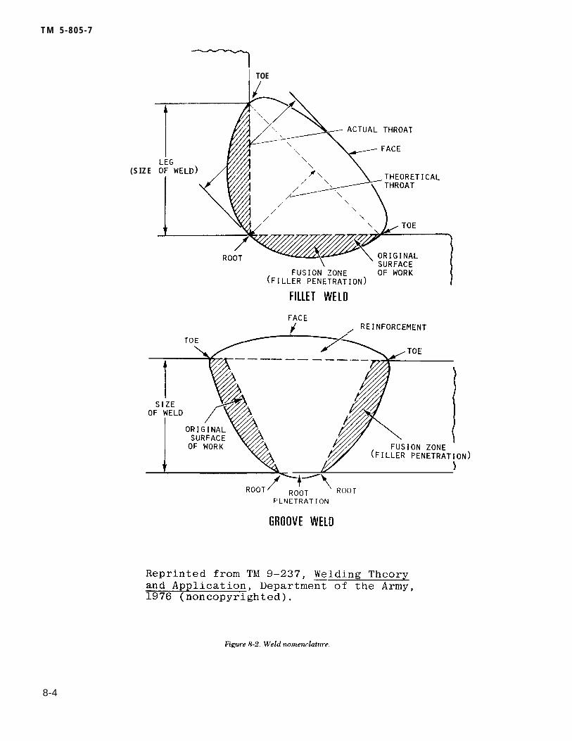
T M 5 - 8 0 5 - 7
I TOE
( S I Z E
8-4

T M 5 - 8 0 5 - 7
MAGNETICOF
LINESFORCE
(2) DC, AC, and half-wave rectified currentmay be used for magnetization. High-amperage,low-voltage current is usually employed. If only sur-face defects are to reinspected, AC can be used.DC isused for the detection of subsurface disconti-nuities because the current penetrates throughoutthe part. Maximum sensitivity is provided by usinghalf-wave rectified, single-phase current. The pul-sating field increases the particle mobility andenables the particles to lineup more readily in weak
(3) The magnetic particles may be applied tothe weld either as a dry powder or as a suspension ina light oil. The particles used are carefully selectediron oxide particles of the proper size, shape, mag-netic permeability, and retentivity. Dry particles arein powder form and may be obtained in gray, red, orblack for contrast. These particles are applied usinghand shakers, spray bulbs, shaking screens, or anairstream. Wet particles consist of particles sus-pended in a light petroleum oil or kerosene. They
leakage fields. The pulse peaks also produce a can be applied - b yhigher magnetizing force, which is needed in the from aerosol cans.inspection of welds.
dipping, immersing, or sprayingThe particles can be colored or
8-5

T M 5 - 8 0 5 - 7
have a fluorescent coating for viewing with ultravio-let light. Wet particles provide better control andstandardization of the concentration of magneticparticles through control of the concentration of sus-pension. The wet procedure is more sensitive for thedetection of extremely small discontinuities belowthe surface. Excess powder should be removed witha stream of air of just enough force to carry theexcess away without disturbing lightly held powderpatterns.
(4) A method of applying the bath or particlesafter the magnetizing current has been turned off iscalled the “residual method. ” This method of apply-ing the particles is effective on materials that willretain their magnetism, i.e., those having high reten-tivity. Steel that is relatively high in carbon andother alloys responds most favorably to this method.Most construction steels, however, have low reten-tivity and will not hold a strong enough magneticfield for this method. The recommended method forconstruction steels is the “continuous method”; mag-netizing is done at the same time the inspectionmedium or particles are applied. This method is par-ticularly useful when inspecting low carbon or alloysteels. Because of their low retentivity, the partscannot maintain enough residual magnetism to holdthe particles needed to indicate a defect. Whetherwet or dry continuous methods are used, the inspec-tor must be careful not to wash or shake off themagnetic particle indications. Excessive currentmust not be used during magnetizing because thismay produce irrelevant indications. Because of thestrong field produced, the continuous method isespecially useful in locating subsurface defects.
(5) When current is passed through a coil whichis wrapped around a material, a magnetic field isproduced in that material. This is called longitudinalmagnetization. When clamps or prods are used topass the current through the material, the procedureis called circular magnetization. The two methodsproduce magnetic fields in different directions,thereby permitting the inspector to examine a mate-rial for discontinuities in all directions.
b. Equipment. Var ious types of magnet iz ingequipment are available. Units with electromagnetsand permanent magnets are commonly used, but aredesigned for locating surface cracks. Although sucha unit can locate some subsurface defects, its depthof penetration is severely limited. Direct currentequipment provides the great depth of penetrationneeded to detect subsurface flaws. Some equipmenthas both full-wave and half-wave rectified directcurrent (HWDC). HWDC is particularly suitable foruse with dry particles because the pulsating fieldprovides excellent mobility to the powder particles,
Since most construction steels have low retentivity,demagnetization is generally not required; however,most magnetic particle inspection units can demag- netize after inspection.
c. Inspect ion procedures . The proceduresdecribed substantially conform to ASTM E 138 andASTM E 709. MIL-I-6868 and the ASME Boiler andPressure Vessel Code, section V, also outline inspec-tion procedures. The surface of the weld usuallydoes not require grinding or smoothing before test-ing. However, if the edges of the weld are undercutor-if the bead surface is extremely rough, the weldshould be ground smooth and the edges blendedinto the base metal surface before magnetic particleinspection. The surface should be cleaned of allgrease, oil, loose rust, or water because such materi-a ls in ter fere wi th the par t ic les which indica tedefects.
(1) The “prod method” of weld inspection iswidely used. Portable prod-type electrical contactsare pressed against the surface of the material nextto the weld, as shown in figure 8-4. The prodsshould not be spaced more than 8 inches apart. Ashorter prod spacing with a minimum of 3 inchesmay be used to increase sensitivity. When the prodsare positioned, the operator turns the current onand applies the magnetic particle powders. The cur-rent is turned off before the prods are removed inorder to prevent arcing. At least two separate exami- nations should be done for each area. The prods arerepositioned so that the lines of flux from one opera-tion are approximately perpendicular to the lines offlux from the previous operation. Contact clampssometimes can be used instead of prods.
(2) The weld must be examined immediatelyafter the excess powder has been removed andbefore the position of the prods is changed. Surfacedefects appear as sharp indications, while subsurfaceindications are broad, diffuse patterns.
(3) Acceptance standards are written based onthe object’s intended use. Standards vary, but mostspecify similar limits for possible defects.
8-7. Penetrant inspectionPenetrant inspection is a sensitive, nondestructivemethod of locating minute flaws open to the surface— for example, cracks, pores, and leaks. It is partic-ularly valuable for examining nonmagnetic materi-als, on which magnetic particle inspection cannot beused. Penetrant inspection is used extensively forexposing surface defects in aluminum, magnesium,and austenitic stainless steel weldments, and forlocating leaks in all welds. Dye penetrant proce-dures usually require ground surfaces, althoughsome “as-welded” surfaces can be inspected. —
8-6

T M 5 - 8 0 5 - 7
(Improper grinding can smear the surface and closesurface openings of the defects.) The efficiency ofthe method depends on the inspector’s ability torecognize and evaluate the visual indications offlaws.
a. Principles of liquid penetrant inspection. In liq-uid penetrant inspection, both visible and fluores-cent, the surface of a material is coated with a film ofpenetrating liquid (fig 8-5). The liquid is allowed toseep into any flaws that are open to the surface, andthe excess surface film is removed. A developer isthen applied; it draws the penetrant from a disconti-nuity to the surface so the inspector can see theflaw.
(1) Liquid penetrant inspection can be donequickly and easily; it costs less per foot of weldinspected than any other nondestructive methodexcept visual inspection. The initial cost of training,equipment, materials, and supplies is much less thanthat of any other inspection method. However, sur-face poros i ty and improper surface c leanl inessreduce the sensitivity of the inspection technique;contaminants such as water, oil, and grease cancover or fill discontinuities so the penetrant does notenter. Penetrant inspection methods are used tocheck nonporous materials for defects open to thesurface. The following surface defects can be foundwith penetrant inspection: all types of cracks in con-nection with welding, grinding, fatigue, forging,etc.; porosity; seams; laps; cold shuts; or lack ofbond between two metals. Since penetrant methodscan locate only surface defec ts , c leanl iness i sextremely important.
(2) penetrant inspection is equally applicable toboth large and small weldments. In the petrochemi-cal industries, pressure vessels and piping, which areof ten made of nonmagnet ic mater ia ls , can beinspected for surface cracks and porosity by thismethod. Penetrant inspection can be used to detectcracks, pores, and leaks through the lining in cladvessels. This method can be applied to all types ofwelded linings. Shallow cracks and porosity can bedistinguished from those that extend through thelining (leakers). The indications for all cracks andporosity bleed out rapidly or spread upon applica-tion of dry developer.
b. Equipment. The equipment used in penetrantinspection is portable: aerosol cans of cleaner, dye,and developer. When fluorescent penetrant is used,a black light source in the 36-angstrom unit rangeand a hood or dark area are required. Portableinspect ion k i t s for f ie ld use are commercia l lyavailable.
I n s p e c t i o n p r o c e d u r e s . T h e p r o c e d u r edescribed substantially conforms to ASTM E 165.
(1) Either the visible or fluorescent dye pene-t rant method can be used between a ser ies ofstringer welds or on a completed weld. There arethree types of penetrant: water washable, post emul-sifying, and solvent removable. Intermixing thesepenetrant materials is not permitted. Procedures forinspection depend on the specific type of penetrantand the method used; therefore, only a generalapproach is outlined in this manual.
8-7
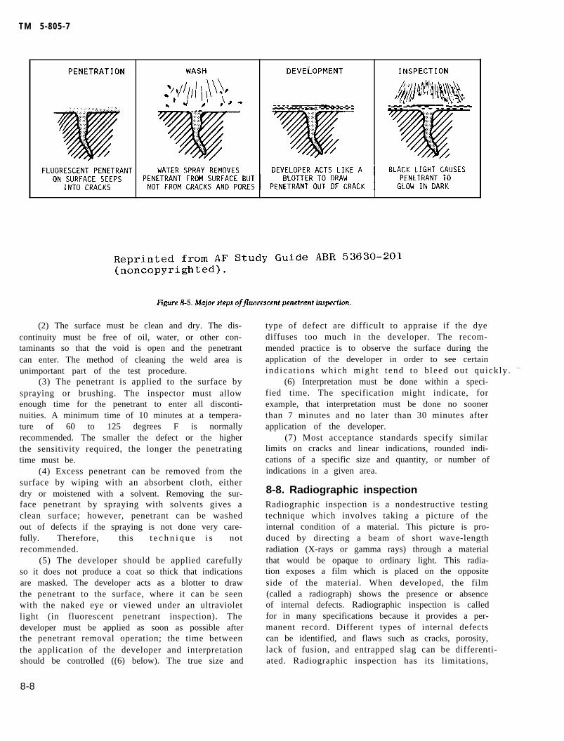
TM 5-805-7
(2) The surface must be clean and dry. The dis-continuity must be free of oil, water, or other con-taminants so that the void is open and the penetrantcan enter. The method of cleaning the weld area isunimportant part of the test procedure.
(3) The penetrant is applied to the surface byspraying or brushing. The inspector must allowenough time for the penetrant to enter all disconti-nuities. A minimum time of 10 minutes at a tempera-ture of 60 to 125 degrees F is normallyrecommended. The smaller the defect or the higherthe sensitivity required, the longer the penetratingtime must be.
(4) Excess penetrant can be removed from thesurface by wiping with an absorbent cloth, eitherdry or moistened with a solvent. Removing the sur-face penetrant by spraying with solvents gives aclean surface; however, penetrant can be washedout of defects if the spraying is not done very care-fully. Therefore, this t e c h n i q u e i s notrecommended.
(5) The developer should be applied carefullyso it does not produce a coat so thick that indicationsare masked. The developer acts as a blotter to drawthe penetrant to the surface, where it can be seenwith the naked eye or viewed under an ultravioletlight (in fluorescent penetrant inspection). Thedeveloper must be applied as soon as possible afterthe penetrant removal operation; the time betweenthe application of the developer and interpretationshould be controlled ((6) below). The true size and
type of defect are difficult to appraise if the dyediffuses too much in the developer. The recom-mended practice is to observe the surface during theapplication of the developer in order to see certainindica t ions which might tend to b leed out quickly . —
(6) Interpretation must be done within a speci-fied time. The specification might indicate, forexample, that interpretation must be done no soonerthan 7 minutes and no later than 30 minutes afterapplication of the developer.
(7) Most acceptance standards specify similarlimits on cracks and linear indications, rounded indi-cations of a specific size and quantity, or number ofindications in a given area.
8-8. Radiographic inspectionRadiographic inspection is a nondestructive testingtechnique which involves taking a picture of theinternal condition of a material. This picture is pro-duced by directing a beam of short wave-lengthradiation (X-rays or gamma rays) through a materialthat would be opaque to ordinary light. This radia-tion exposes a film which is placed on the oppositeside of the material. When developed, the film(called a radiograph) shows the presence or absenceof internal defects. Radiographic inspection is calledfor in many specifications because it provides a per-manent record. Different types of internal defectscan be identified, and flaws such as cracks, porosity,lack of fusion, and entrapped slag can be differenti- ated. Radiographic inspection has its limitations,
8-8
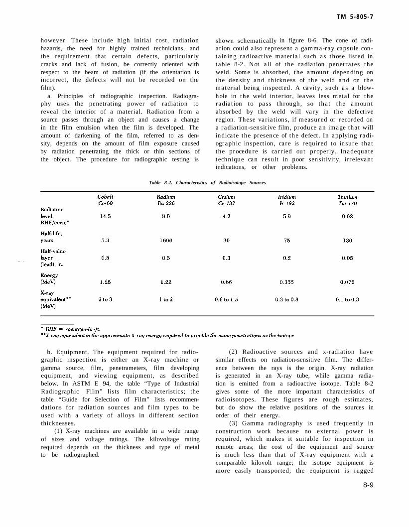
however. These include high initial cost, radiationhazards, the need for highly trained technicians, andthe requirement that certain defects, particularlycracks and lack of fusion, be correctly oriented withrespect to the beam of radiation (if the orientation isincorrect, the defects will not be recorded on thefilm).
a. Principles of radiographic inspection. Radiogra-phy uses the penetrating power of radiation toreveal the interior of a material. Radiation from asource passes through an object and causes a changein the film emulsion when the film is developed. Theamount of darkening of the film, referred to as den-sity, depends on the amount of film exposure causedby radiation penetrating the thick or thin sections ofthe object. The procedure for radiographic testing is
shown schematically
T M 5 - 8 0 5 - 7
in figure 8-6. The cone of radi-—ation could also represent a gamma-ray capsule con-taining radioactive material such as those listed intable 8-2. Not all of the radiation penetrates theweld. Some is absorbed, the amount depending onthe density and thickness of the weld and on thematerial being inspected. A cavity, such as a blow-hole in the weld interior, leaves less metal for theradiation to pass through, so that the amountabsorbed by the weld will vary in the defectiveregion. These variations, if measured or recorded ona radiation-sensitive film, produce an image that willindicate the presence of the defect. In applying radi-ographic inspection, care is required to insure thatthe procedure is carried out properly. Inadequatetechnique can result in poor sensitivity, irrelevantindications, or other problems.
Table 8-2. Characteristics of Radioisotope Sources
b. Equipment. The equipment required for radio-graphic inspection is either an X-ray machine orgamma source, film, penetrameters, film developingequipment, and viewing equipment, as describedbelow. In ASTM E 94, the table “Type of IndustrialRadiographic Film” lists film characteristics; thetable “Guide for Selection of Film” lists recommen-dations for radiation sources and film types to beused with a variety of alloys in different sectionthicknesses.
(1) X-ray machines are available in a wide rangeof sizes and voltage ratings. The kilovoltage ratingrequired depends on the thickness and type of metalto be radiographed.
(2) Radioactive sources and x-radiation havesimilar effects on radiation-sensitive film. The differ-ence between the rays is the origin. X-ray radiationis generated in an X-ray tube, while gamma radia-tion is emitted from a radioactive isotope. Table 8-2gives some of the more important characteristics ofradioisotopes. These figures are rough estimates,but do show the relative positions of the sources inorder of their energy.
(3) Gamma radiography is used frequently inconstruction work because no external power isrequired, which makes it suitable for inspection inremote areas; the cost of the equipment and sourceis much less than that of X-ray equipment with acomparable kilovolt range; the isotope equipment ismore easily transported; the equipment is rugged
8-9
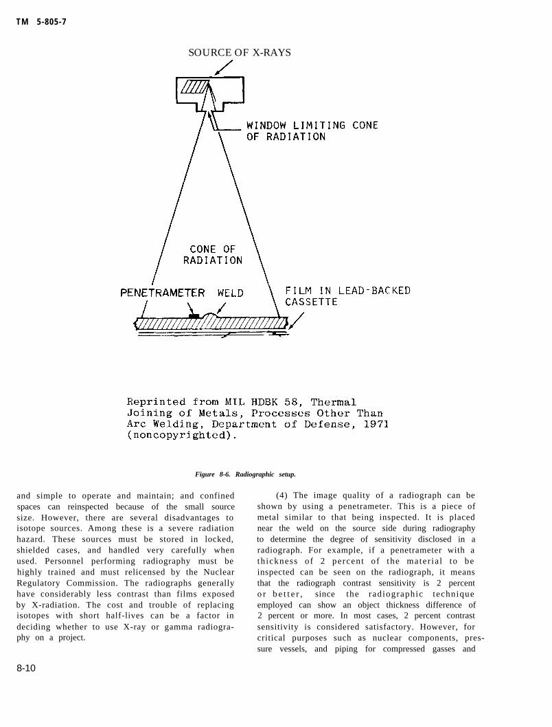
TM 5-805-7
SOURCE OF X-RAYS
Figure 8-6. Radiographic setup.
and simple to operate and maintain; and confinedspaces can reinspected because of the small sourcesize. However, there are several disadvantages toisotope sources. Among these is a severe radiationhazard. These sources must be stored in locked,shielded cases, and handled very carefully whenused. Personnel performing radiography must behighly trained and must relicensed by the NuclearRegulatory Commission. The radiographs generallyhave considerably less contrast than films exposedby X-radiation. The cost and trouble of replacingisotopes with short half-lives can be a factor indeciding whether to use X-ray or gamma radiogra-phy on a project.
(4) The image quality of a radiograph can beshown by using a penetrameter. This is a piece ofmetal similar to that being inspected. It is placednear the weld on the source side during radiographyto determine the degree of sensitivity disclosed in aradiograph. For example, if a penetrameter with ath ickness of 2 percent of the mater ia l to beinspected can be seen on the radiograph, it meansthat the radiograph contrast sensitivity is 2 percento r b e t t e r , since the radiographic techniqueemployed can show an object thickness difference of2 percent or more. In most cases, 2 percent contrastsensitivity is considered satisfactory. However, forcritical purposes such as nuclear components, pres- sure vessels, and piping for compressed gasses and
8-10


T M 5 - 8 0 5 - 7
bridges, a lower percentage is desired. In other clas-ses of work, a higher percentage maybe acceptable.To demonstrate detail sensitivity, holes in the pene-trameter are used; their diameters are, in terms ofeffect, artificial flaws of known dimensions. Theholes are usually expressed in the thickness of thepenetrameter. Construction details of penetrame-ters are shown in figure 8-7.
(5) The radiographic film must be Class 1, extrafine grain, and Class 2, fine grain. Both classes offilm give high contrast. Extra fine grain film hasgreater sensitivity than fine grain (i.e., revealsmaller discontinuities). However, exposure timesmay be as much as 50 percent longer since moreexposure to radiation is needed to develop an image.Film holders must be flexible, and intensificationscreens must be made of lead. Front screens shouldbe 0.005 inch and back screens 0.010 inch.
(6) Film processing equipment can be eithermanual or automatic. Processing systems should con-tain separate tanks for developing, short stop orwashing, fixing, and final washing. Film driers mustnot cause processing defects.
(7) A densitometer or a density strip is neededto make sure film density requirements have beenmet. Density, a measure of the degree of blackness,is a function of exposure time and intensity of theradiation to which film is subjected. The radiogra-pher controls these variables.
c. Inspection procedure. The procedure describedsubstantially conforms to ASTM E 94, ASTM E 142,and AWS D1.1. Procedures are also outlined inMIL-R-11470, MIL-STD-453, and the ASME Boilerand Pressure Vessel Code, section V.
(1) Radiographs must be made by either the X-ray or isotope radiation methods. If the level 2-2Tr a d i o g r a p h y - is required, all radiographs shouldreveal discontinuities with thicknesses equal to orgreater than 2 percent of the thickness of the thin-ner part joined by the weld being examined. In the“2-2T” designation, the first digit 2 means 2 percentsensitivity and 2T the diameter of the hole in thepenetrameter which must be clearly visible in theradiograph. Class 1 or 2 film must be used. The filmmust be clean and free of processing defects. It musthave a density of not less than 1.5 nor more than4.0, although densities within the range of 2.5 to 3.5are preferred. Radiographs will show:
(a) The smallest hole in each penetrameter asspecified in the specification.
( b ) T h e r a d i o g r a p h i d e n t i f i c a t i o n a n dlocation.
(2) Welds that are to be radiographed need notbe ground or otherwise smoothed for radiographictesting unless the surface irregularities interfere
with the desired radiographic image. When weldreinforcement or backing is not removed, shims ofthe mater ia l be ing radiographed must be p laced _under the penetrameter. These shims must make thetotal thickness of material between the penetrame-ter and the film at least equal to the average thick-ness of the weld measured through its reinforcementand backing.
(3 Pnetrameters must be placed on the side ofthe work near the radiation source adjacent and par-allel to the weld, A radiograph identification markand two location identification marks, all of whichare to show in the radiograph, must be placed on thematerial at each radiograph location.
(4) Film holders must be placed tightly againstthe test item whenever possible. Shielding beyondthe film holder should be provided when practical.The operator must use radiation detection devices,including survey meters, f i l m b a d g e s , a n ddosimeters.
(5) Film must be processed so that the radi-ographs are of h igh qual i ty . F i lms conta in ingmechanical, chemical, or other processing defectsthat could interfere with proper interpretation ofthe radiograph are not acceptable.
(6) Radiographs are viewed using a high-inten-sity light source that has adjustable levels from dimto a brightness that penetrates without difficultyradiographs with a density of 4.0. Radiographs mustbe checked for proper placement of identificationnumbers and penetrameters. All indications must beinterpreted and marked.
(7) The interpreter must be familiar with thestandards for acceptance or rejection. Most stan-dards agree about the types of discontinuities whichare not acceptable, but there are some differences.Defects such as cracks or zones of incomplete fusionor penetration would be cause for rejection. Poros-ity of one size or aggregate lengths might also because for rejection, while other sizes or lengthswould be acceptable. Reference radiographs areindicated in ASTM E 94, MIL-STD-779, and MIL-R-45774.
8-9. Ultrasonic inspectionUltrasonic inspection is a rapid, efficient, nonde-structive method of detecting, locating, and measur-i n g b o t h s u r f a c e a n d s u b s u r f a c e d e f e c t s i nweldments and/or base materials. An ultrasonic is anenergy wave form with frequencies above 20,000Hertz. The ultrasonic wave is introduced into thematerial being tested by a piezoelectric transducerplaced in contact with the test specimen. The ultra-sound enters the specimen and is reflected back tothe t ransducer when i t encounters an in ter face tha t
8-12

Table 8-3. Comparison of Ultrasonics With Other Techniques
Radiography1. Porosity 1.
2. Inclusions 2.
3. Large cracks 3.
4. Lack of fusion 4.
5. Lack of penetration 5.
6. Small cracks
could be a flaw or the back surface of the material.These vibrations are converted to electric signals,amplified, and displayed on a cathode ray tube(CRT) screen as indications. Because of the high fre-quency (above the range for the human ear), theshort wave-length allows small flaws to be detected.Ultrasonics is one of the most commonly used tech-niques for subsurface flaw detection in weldments.Ultrasonic inspection is specified to detect bothinternal and surface flaws in all types of weldedjoints. Defects such as slag inclusions, porosity, lackof fusion (cold shuts), lack of penetration (rootdefects), and longitudinal and transverse cracks canbe detected. Since only one inspection surface isusually required, many types of welded joints can besatisfactorily inspected. When a flaw is found, it canbe measured and evaluated. Dimensions such asdepth, width, and length can be measured if onesurface is accessible.
a . Pr inc ip les of u l t rasonic inspect ion . Mostultrasonic testing is performed with a single straightor angle beam transducer depending on the designof the weld joint to be inspected. The transducer,sometimes referred to as a crystal or search unit, cant ransform e lec t r ica l vol tage genera ted by theultrasonic unit into mechanical vibrations or ultra-sound. The t ransducer a lso can conver t thereturning vibrations from a test specimen into elec-trical energy; they are displayed in this form on theultrasonic unit’s CRT. This capability to convertfrom electrical energy to mechanical vibrations andback again is called the piezoelectric effect. Theelectrical signal striking the transducer, usually notmore than 1 microsecond in duration, makes thetransducer vibrate during the driving period. Theduration of the pulse is short, so that returning orreflected echoes from defects or boundaries lyingclose to the surface will appear as a separate indica-tion, as shown in figure 8-8. Such a presentation is
called an A-scan and is a “time versus amplitudedisplay.” From the pip or pulse location on the CRTtime line and its height of amplitude, the relativedepth and size of the discontinuity can be estimated.
(1) Ultrasonic inspection has many advantagesover other methods. It is fast, and the equipment iscompact and portable. Unlike radiographic inspec-tion, it involves no time delay while film is beingprocessed and poses no radiation hazard to personsworking in the inspection area. Indications of flawscan be seen immediately on the CRT. Both internaland surface flaws can be detected (though shallowsurface cracks are more easily and reliably detectedwith magnetic particle or liquid penetrant). Sincethere are no expandable materials, the inspectioncan be performed faster and at a lower cost thanradiography. Certain types of defects not readilydetectable by other inspect ion methods can befound by ultrasonics. By using calibrated standardsand a few calculations, the inspector can classify heindications as irrelevant, acceptable, or unaccept-able. Ultrasonic inspection has a higher sensitivitylevel than does radiographic inspection. Ultrasonicinspection is more sensitive to crack detection as themater ia l th ickness increases ; for radiographicinspection, the opposite is true. Table 8-3 comparesultrasonics and radiographic, magnetic particle, andliquid penetrant inspection.
(2) Ultrasonic inspection has some limitationsthat have restricted its use. Chief among these arethe difficulty in interpreting the oscilloscope pat-terns and the need for standards to calibrate theinstrument. This procedure produces no permanentrecords showing flaws and their location. A highdegree of operator skill and training is required tointerpret the oscilloscope patterns reliably. Flaws,such as cracks, oriented parallel to the sound beammay not be detec ted . This means a d i f ferentultrasonic inspection technique must be used. The
8 - 1 3
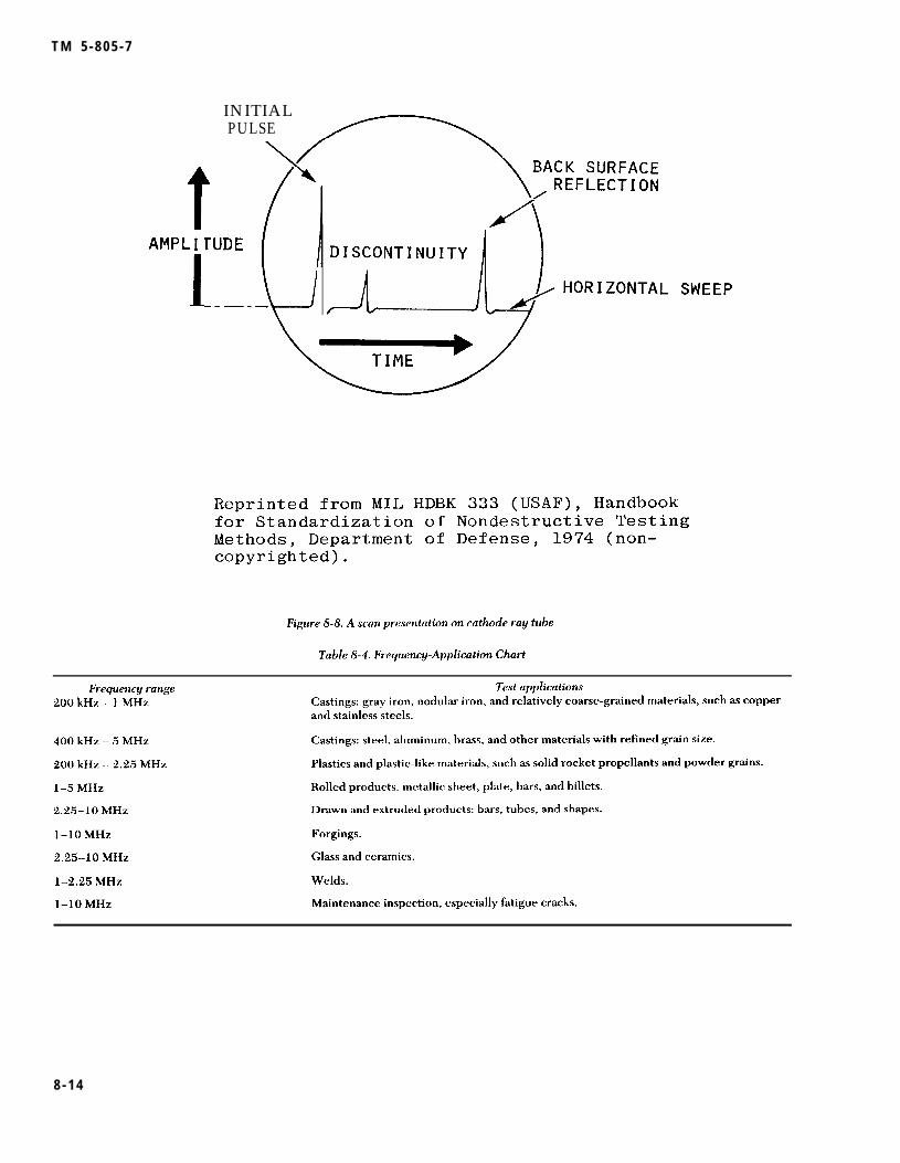
T M 5 - 8 0 5 - 7
INITIALPULSE
8 - 1 4

T M 5 - 8 0 5 - 7
surface of the material must be free from weld spat-ter and must be smooth enough to allow effectivecoupling between the transducer and the material.Surface roughness can cause scattering and absorp-tion of the sound. Also, a rough surface will createundue wear on the crystal surface of the transducer,causing premature failure. A viscous coupling agentsuch as glycerine is necessary to eliminate the com-pressible air which prevents sound (mechanicalvibrations) from entering the material from thetransducer. The coupling agent can be any liquid,grease, or paste which fills surface depressions orpits.
(3) Two important considerations in selecting atransducer are its diameter and operating frequency.The higher the frequency, the greater the sensitivitywill be. This advantage may be offset if lower fre-quencies are needed to penetrate coarse-grained orvery thick materials. Table 8-4 shows the ultrasonicfrequency ranges that may be used on var iousapplications.
(4) Transducers generally fall into three groups:straight beam, angle beam, and surface wave.
(a) Longi tudinal wave, somet imes ca l ledstraight beam, directs the sound waves into thematerial in a direction perpendicular to the surfaceof the part. This method is used mainly to detect
subsurface defects in base metals, but should bespecified for some weld inspection, as shown in fig-ure 8-9.
(b) The angle beam method, sometimes calledshear wave, is usually the required procedure forweld inspection. The vibrational wave is introducedinto the material at an angle of 30 to 80 degreesfrom the perpendicular to the material surface. Thisangle will vary with the material’s thickness. A lon-gitudinal transducer is mounted on plastic wedgescut at specific angles, usually 70, 60, or 45 degrees.By varying the position of the angle beam searchunit with respect to the weld, flaws at any location inthe weld joint can be detected, as shown in figure8-10.
(c) Surface waves are generated by mode con-version so that the refracted wave will travel alongthe surface. Surface waves follow curved surfacesand detect surface and near-surface defects. Thistechnique has many applications in industry, but isseldom used for weld inspection.
b. Equipment. The equipment for ultrasonic weldinspection is a pulse-echo-type ultrasonic test unitthat can generate, receive, and present on a CRTscreen pulses in the frequency range from 0.2 to 10megahertz.
8 - 1 5

INSPECTIONZONE
8 - 1 6

(1) Transducers will consist of straight beam andangle beam types in the frequency range of 2 to 2.4megahertz. Angle beam transducer angles of 70, 60,and 45 degrees are to be used.
(2) A coupling material is needed to exclude air.Typica l coupl ing mater ia ls inc lude water , o i l ,grease, pastes , and glycerine. General ly , therougher the surface, the more viscous the couplingagent required.
(3) Ultrasonic reference blocks are usuallyneeded to check the sensitivity and performance oful t rasonic ins t rumenta t ion and t ransducers forinspecting critical welds. Most standards are manu-factured with artificial defects in the form of drilledholes with flat, round, or conical bottoms or slotsmachined into the surface. AWS D1.1 recommendsseveral standards, the most common being the Inter-national Institute of Welding (IIW) reference blockshown in figure 8-11.
Inspect ion procedures . The proceduresdescribed conform to ASTM E 164 and AWS D1.1.Ultrasonic inspection procedures are also outlined inappendix U to the ASME Boiler and Pressure VesselCode, Section VIII, Division 1, and in Section V,Article 5. In ultrasonic inspection, the most impor-tant phase is the interpretation of indications. Inpreparing for an ultrasonic inspection, an operatormust consider certain parameters: type and size oftransducer, couplant, scanning procedures, peakingtechniques, frequency, pulse length, linearity of
indications, distance/time relationship, and sensitiv-ity/time relationship. Other parameters are speci-men properties, such as material sound/velocity;specific acoustic impedance; part geometry; mate-rial attenuation; and noise level. Each signal peakalong the scan line represents a place in time wherethe acoustic energy has encountered an interface ora multiple of a previously generated signal. Byknowing the beam path and spread, the operator caninterpret the signal and separate relevant from irrel-evant indications. The operator must considerampl i tude/d is tance response and ampl i tude/arearesponse when determining flaw size. The shape andorientation of the flaw also affect the signal ampli-tude. In attempting to determine flaw size, an opera-tor must watch both the flaw signal amplitude andthe loss of amplitude of the back reflection.
(1) Before any inspection, the ultrasonic unitmust be calibrated for sensitivity and horizontalsweep (distance); a calibration block or other recog-nized method must be used.
(2) The surface of the weld area to be inspectedmust be free of weld spatter (which will cause rapidwear of the transducer), grease, dirt, oil, and loosescale (which will cause scattering and attenuation).Tight layers of paint need not be removed unless thethickness exceeds 10 roils.
(3) A coupling agent must be used between thesearch unit and the metal. The base metal is firstexamined for lamella flaws using a straight beamsearch unit, and then is inspected using the angle

8 - 1 8

T M 5 - 8 0 5 - 7
beam. Where possible, all welds should be scannedfrom both sides on the beam face for longitudinaland transverse discontinuities. The search unit mustbe placed on the surface with the sound beam aimedabout 90 degrees to the weld and manipulated later-ally and longitudinally so that the ultrasonic beampasses through all of the weld metal.
(4) For welds not ground flush (fig 8-12), shearwave is used in four different scans. For longitudinalflaws, sound is directed into the weld from eachside. The transducer is oscillated to the left and rightwith an included angle of about 30 degrees. Todetect transverse defects, the transducer is placedon the base metal at the edge of the weld. It is thenpositioned so that the sound beam makes about a 15-degree angle to the longitudinal axis of the weld. Toscan, the search is moved along the weld edge fromboth sides. For welds ground flush (fig 8-13), scan-ning is done similarly. However, to detect longitudi-nal flaws the transducer is moved across the weld.And for transverse defects, the transducer is oscil-lated left and right through a 30-degree angle whilecontinuously advancing along the top of the weld.
(5) When an indication of a flaw appears on theCRT, the location and position of the transducer arerecorded. By using graphs, calculators, or guides,the operator can accurately locate the position ofthe defect in the weld. By using applicable chartsand attenuation factors, the weld discontinuity canbe accepted or rejected.
8-10. Destructive testingIn procedure qualification testing and weldingdevelopment work, metallographic specimens aresometimes removed from a structure to check thequality of the weldment. These tests are used todetermine visually the characteristics of the welds.Metallographic test samples are sections cut throughthe welds in any desired plane, then polished andetched to reveal the structure. These specimens maybe examined with the naked eye or with variousmagnifications, including microscopic, Among thecharacteristics that can be checked are the sound-ness, location, and depth of penetration of thewelds; the metallurgical structures of the weld,fusion zone, and heat affected zone; the extent anddistribution of undesirable inclusions in the weld;hardness gradients; and the number of weld passes.When metallographic specimens are removed fromany part of a structure, repairs must be made byqualified welders or welding operators usingaccepted welding procedures. Peening or heat treatment may be required to develop the full strength of
a. Test methods. There are three categories ofdestructive tests: chemical, hardness, and mechani-cal tests.
(1) Chemical tests. Chemical tests are generallyused to validate the chemical composition or thecorrosion resistance of the base and weld metals.Particular compositions of the metals involved, forexample, may be examined for conformance tospecifications. In addition, chemical analysis of theweld metal can show whether welding produced theexpected results, or whether it introduced undesir-able constituents into the weld metal. corrosiontests demonstrate a weldment’s capability to with-stand the corrosive environment to be encountered inservice. Because of the cost and time involved, aweldment usually cannot be tested for corrosionresistance by actual use under service conditions.Therefore, accelerated corrosion tests that can beconducted under laboratory conditions have beendeveloped.
(2) Hardness tests. Hardness tests measure theresistance of materials to wear. For most metals,ductility and corrosion resistance decrease as thehardness increases. Since each operation duringwelding has metallurgical effects, some specifica-tions call for an upper limit to the acceptable hard-ness of various areas of weld. Hardness testing isdone with equipment which, under a specific load,forces a small hardened steel ball or diamond pointinto the. surface of the metal. The depth of penetra-tion is either measured directly by the machine, orinferred from the dimensions of the impression. Byassociating a number with each possible impressiondepth, the inspector can develop a hardness scale.This testing approach is used by the three most com-mon hardness measuring devices: the Brinell,Rockwell, and Vickers hardness testers. Hardnessnumbers may vary from method to method becauseof differences in the formulas used to define hard-ness numbers, in the material type and shape used tomake the impression, and in the imposed load. How-ever, tables of approximately equivalent hardnessnumbers have been constructed.
(3) Mechanical tests. Mechanical tests (exclusiveof hardness) have been designed to test several weldproperties.
(a) Tensile tests are conducted on specimensmachined from a test weld and are used to measurethe strength of the weld joint. Specimens are usuallytaken perpendicular to the weld, which is centeredin the specimen (fig 8-14). However, specimens aresometimes taken along the weld and consist entirelyof weld metal. Specimens may have round or rectan-gular cross sections, depending on the requirementsof the applicable welding code. The testing machine

TM 5-805-7
applies a tensile force until the specimen ruptures.From readings on the machine and measurements ofthe specimen before and after the test, propertiessuch as yield point or yield strength, ultimatestrength, and ductility are calculated. The primarypurpose of the test is to demonstrate that the weldmetal deposited by the selected procedures meetsor exceeds the minimum values specified in theapplicable code or specifications.
(b) Guided bend tests indicate a weld’s ductil-ity. Test specimens are described as root-bend, face-bend, or side-bend, depending on the surfacestretched in bending. Rectangular test specimenssimilar to those prepared for tensile tests aremachined or ground to remove any weld reinforce-ment. A test jig, such as that shown in figure 8-15, isused to make the bend. with the plunger removed,the specimen is placed across the shoulders of thejig with the weld centered. The plunger is thenforced down until the specimen is bent into a U-shape. The elongation of the tension surface isdetermined by the relationship between the thick-ness of the specimen and the radius of the die. The
specimen fails if it has cracks or other open defectsgreater than a specified number and size, or if itfractures.
(c) Free bend tests, also for ductility, usespecimens similar to those for guided bend tests.Before the test, gage lines are inscribed across thewidth of the sample of deposited weld metal. Theselines mark off a distance about 1/8 inch less than thewidth of the weld. The sample is given an initialbend (fig 8-1 6) by supporting the ends or shoulderson rollers, then forcing the center down until thespecimen takes a permanent set. Next, a testingmachine or device (fig 8-16) is used to compress thesample longitudinally until a crack or depressionappears on the convex face of the specimen, or untilthe specimen is bent double. The load is removedimmediately if a defect appears before the specimenis bent double. Percent elongation is calculated fromthe initial and final distances between the gagemarks.
(d) Shear tests of fillet welds are conducted bypulling specimens apart in a testing machine. Thedimensions of the specimens make it easy to use the
8 - 2 0

T M 5 - 8 0 5 - 7
FORCE
+
test results to obtain shear strength in pounds perlinear inch of weld. Figure 8-17 shows the shear testspecimen and indicates where to machine specimensfrom test weldment.
(e) Nick-break tests are required in somewelding codes to detect weld defects. The nick-break test specimens similar to a rectangular ten-sile-test specimen, except that notches are cut at thecenter of the weld. The specimen is then brokeneither by pulling in tension or by bending. The spec-imen is forced to break in the weld metal because ofthe notches. After the specimen has been broken,the fracture surfaces are examined for weld-metaldefects. If there are more than the minimumallowed, the weld is rejected.
(f) Various types of impact tests are some-times used to test the fracture toughness of the weldmetal when low-alloy, high-strength steels are being
welded. These tests measure the weld metal’s capa-bility to resist crack propagation under low stress.
b . Sampl ing technique , Removal of samples bysectioning is an accepted method of weld inspectionapproved by various pressure-vessel codes. Because
the cavity must later be repaired by rewelding, themethod is sometimes considered a destructive test.Samples may be taken for chemica l ana lys is , e tchtests, subsize tension, or impact tests. The specificmethod of removing samples depends on the size ofspec imen needed; hole saws , bo l t cu t te rs , co ldchisels, or trepanning tools — a special power toolwith a hemispherical saw — are often used for sam-ple removal. The samples must be carefully selectedto be representative of the weld or base metal being
checked.
8-21

T M 5 - 8 0 5 - 7
1 INITIAL S E T
8 - 2 2

1
1/2”
r

TM 5-805-7
8-11. Leak testingLeak tests are similar to proof tests for closed pres-sure vessels; the container being tested is filled witha fluid at a specified pressure. The choice of liquidor gas depends on the purpose of the container andthe leakage that can be tolerated. For example, con-tainers that are watertight may not be oiltight orgastight. Leaks can be detected in several ways. Foroil or water, visual inspection of the outside of thepressure vessel may suffice. Leaking air or gas canbe detected by the sound of the escaping gas, by useof a soap film that forms bubbles as gas escapesbeneath it, or by immersion in a liquid in which theescaping gas forms bubbles. For hydrostatic or gastests, a pressure gage attached to the vessel indicatesleaks by the drop in pressure after the tests begin.Dyes introduced into liquids and tracers introducedinto gases can also indicate leakage. Weld defectsthat cause leakage are not always detected by theusual nondestructive testing methods. A tight crackor fissure may not appear on a radiograph, yet willform a leak path. A production operation, such asforming or a proof test, may make leaks develop inan otherwise acceptable weld joint. A leak test isusually done on the completed vessel if all of theweld joints can be inspected; at this stage there willbe no more fabricating operations after the inspec-tion. Inspection is easier if the vessel is empty, Themost common types of leak testing are discussedbelow.
a. The pressure-rise test method is used to seewhether any leaks exist. In this test, the part beinginspected is attached to a vacuum pump and evacu-ated to a pressure of ().5 psi absolute. when thispressure is reached, the connections to the vacuumpump are sealed off, and the internal pressure of thepart is measured immediately. The pressure is mea-sured again after at least 5 minutes (with the itemstill sealed off from the vacuum pump). If the pres-sure in the evacuated space remains essentially con-stant, the welds are free of leaks. If there is apressure rise, at least one leak is present, and thehelium-leak test described in b below must be used,
b. The helium-leak test is more precise than thepressure-rise method and is used to find the exactlocation of these leaks. Helium-leak testing is slow,however, so it normally is not used to inspect largeitems unless a leak definitely exists. This inspectionmethod requires the use of a helium mass spectrom-eter to detect the presence of helium gas. The massspectrometer is connected to the pumping systembetween the vacuum pump and the item beinginspected. Then the item is evacuated by a vacuumpump to a pressure of less than 50 microns of mer-cury. The mass spectrometer can detect helium in
the evacuateddirected at theatmosphere. If
space. A small jet of helium gas isside of the weld joint exposed to thethere is a leak, some of the helium is
sucked through it into the evacuated space, and the mass spectrometer immediately indicates the pres-ence of helium. Of course, if no leak is present, nohelium will enter the evacuated space and no indica-tion will appear on the mass spectrometer. To deter-mine the exact location of leaks, the jet of helium ismoved along the surface of the weld joint. At thesame time, an inspector carefully watches the massspectrometer. If there is an indication, the leak is atthe point where the helium jet is hitting the surfaceof the weld joint.
c. To detect leaks, the ultrasonic translator detec-tor uses the ultrasonic sounds of gas moleculesescaping from a vessel under pressure or vacuum.The sound created is in the frequency range of35,000 and 45,000 Hertz, which is above the rangeof human hearing and is therefore classified asultrasonic. Certain characteristics of these frequen-cies are useful for detections. They are outside therange of most plant and machine noise, and the shortwave length of these frequencies permits the use ofhighly directional microphones. Any system or ves-sel that can be pressurized or evacuated to a pres-sure of 3 psi can be inspected. The operator simplylistens to the translated ultrasonic sounds whilemoving a hand-held probe along the weld (in the same way that a flashlight. is used to illuminate thesuspected leak locations). The detectors are simpleto operate and require minimum operator training.
d. Some of the following tests — particularly theair-soap solution test — can be conducted on a ves-sel during or after assembly. The inspector canlocate large defects in order to reduce the timeneeded for final leak testing. After testing, vesselsshould be thoroughly cleaned to remove all traces ofsoap solution.
(1) Hydrostatic test. This test should conform tothe applicable requirements of a particular vessel orsystem. only distilled or deionized (demineralized)water having a pH of 6 to 8 and an impurity contentnot greater than 5 ppm is used. Traces of watershould be removed from the inside before final leaktesting is begun.
(2) Water submersion test. In this test, the ves-sel is completely submerged in clean water. Theinterior is pressurized with gas, but the design pres-sure must not be exceeded. The size and number ofany gas bubbles indicates the size of leaks,
(3) Soap solution test, In this test, the vessel issubjected to an internal gas pressure not exceedingthe design pressure. A soap or equivalent solution is
8-24

applied so that connections and welded joints can beexamined for leaks.
(4) Air-ammonia test. This test involves intro-ducing air into the vessel until so percent of thedesign pressure is needed. Anhydrous ammonia isthen introduced into the vessel until 55 percent ofthe design pressure is reached; air is then reintro-duced until the design pressure is reached. Eachjoint is carefully examined by using as a probe eithera swab wetted with 10N solution of muriatic acid(HCL), a sulphur candle, or sulphur dioxide. A wispof white smoke indicates a leak.
(5) Halide torch test. In this test, the vessel ispressurized to a value not exceeding the designpressure; a mixture of SO percent Freon and carbondioxide or 50 percent Freon and nitrogen is used.
Each joint is carefully probed with a halide torch todetect leaks, which are indicated by a change in thecolor of the flame.
(6) Halogen snifter test. A Freon inert gas mix-ture is introduced into the vessel until the designpressure is reached. About 1 ounce of Freon forevery 30 cubic feet of vessel volume is required.The inspector passes the probe of a halogen vaporanalyzer over the area to be explored. This probe isheld about 1/2 inch from the surface being testedand is moved at about 1/2 inch per second. Since theinstrument is responsive to cigarette smoke andvapor from newly dry-cleaned clothing, the airshould be kept clean where the test is being done. Inaddition, the test should be done in a substantiallydraft-free enclosure.
8-25

CHAPTER 9
SAFETY
9-1. GeneralThe safety of the welding operators, foreman, andinspectors at the construction job site is a primaryconsideration. All precautions must be taken toensure the safe completion of the construction proj-ect. The Occupational Safety and Health Adminis-tration (OSHA) of the U.S. Department of Labor hasissued Health and Safety Standards covering suchtopics as radiation protection, welding, cutting andheating, use of ladders and scaffolds, steel erection,and hearing and head protection. Most of the stan-dards for welding are in Code of Federal Regula-tions, Title 29, Chapter XVII, Part 1910.
9-2. Hazardsa. Welding and cutting. When welding and cutting
is being done, three major safety hazards must beconsidered and adequate precautions taken. First,the eyes and exposed skin must be protected fromthe intense light radiation and the heat of the weld-ing arc and flames. Second, welding, cutting, andgrinding operations must be prevented from causingfires. Third, care must be taken in handling, weld-ing, and cutting containers that have held combusti-ble or toxic materials. Cutting or welding also mustbe done carefully if materials in the fluxes, coatings,and base metals produce explosive or toxic fumeswhen heated. There are other safety considerations
for welding and cutting operations; all personnelinvolved should be familiar with the requirements ofthe OSHA safety standards. The AWS also publishesand distributes information on safe welding and cut-ting practices.
b. Radiographic inspection. Radiographic inspec-tion involves ionizing radiation. Individuals can beprotected from this radiation primarily by shieldingand distance. For information on safe proceduresand practices for radiography, refer to Title 10,Code of Federal Regulations; the American Societyfor Non-Destructive Testing; and AWS.
c. Noise levels. Hearing loss, either partial ortotal, is a direct result of working without proper earprotection at steel construction sites. Contractorsmust conform to OSHA standards for permissiblenoise levels and time durations.
d. Air quality. Welding and cutting operationsincrease dust and ozone levels near the construc-tion. Welding galvanized steel also releases zincoxide, which can be very hazardous to welding oper-ators and their assistants. Therefore, proper ventila-tion should be provided for all personnel at thewelding site. Particular attention should be paid tosafety when personnel are welding inside largetanks. There should always be ventilation for such anoperation.
9-1

TM 5-805-7
APPENDIX A
REFERENCES
‘ - - - -
Government Publications
Department of Defense.MIL-C-15726E Copper-Nickel Alloy, Rod, Flat Products (Flat Wire, Strip, Sheet, Bar and Plate),
and Forgings.MIL-E-22200F General Specification for Electrodes, Welding Covers.MIL-E-18193 Electrode, Welding, Carbon Steel and Alloy Steel, Bare, Coiled.MIL-E-19822A Electrodes, Welding, Bare, High-Yield Steel.MIL-E-23765/lD Electrodes and Rods-Welding, Bare, Solid, Mild and Alloy Steel.MIL-E-23765/2B Electrode and Rod-Welding, Bare, Solid, Low Alloy Steel.MIL-I-6868 Inspection Process, Magnetic Particle.MIL-R-11468 Radiographic Inspection, Soundness Requirements for Arc and Gas Welds in Steel,MIL-R-11470 Radiographic Inspection, Qualification of Equipment, Operators and Procedures.MIL-R-45774(2) Radiographic Inspection, Soundness Requirements for Fusion Welds in Aluminum
and Magnesium Missile Components.MIL-STD-00453B Radiographic Inspection.MIL-STD-271E Nondestructive Testing Requirement for Metals.MIL-STD-410D Nondestructive Testing Personnel Qualification and Certification (Eddy Current,
Liquid Penetrant, Magnetic Particle, Radiographic and Ultrasonic).MIL-STD-779 Reference Radiographic for Steel Fusion Welds, Vol. I, Vol. II, Vol. III.
Department of the Army.TM 9-237 Welding Theory and Application.
Nuclear Regulatory Commission.1717 H St., NW, Washington, D.C. 20555
General Services Administration (GSA).18th and F Streets, NW, Washington, D.C. 20405 Code of Federal Regulations, Title 10, Chapter I, Parts20 and 34, and Title 29, Chapter XVII, Part 1910, published by the Office of the Federal Register,National Archives and Records Service (Updated Annually)
Occupational Safety and Health Administration (OSHA),Bureau of National Affairs, 1231 25th St., NW, Washington, D.C. 20037
Nongovernment PublicationsAerospace Materials Specification (AMS), Society of Automotive Engineers, 400 Commonwealth Drive,
Warrendale, PA 15096AMS 2635B Radiographic Inspection (updated periodically).AMS 2640H Magnetic Particle Inspection (updated periodically).AMS 2645G Fluorescent Penetrant Inspection (updated periodically).AMS 2646B Contrast Dye Penetrant Inspection (updated periodically).
American Institute of Steel Construction (AISC), 400 N. Michigan Ave., 8th Floor, Chicago, IL 60611Manual of Steel Construction
Aluminum Association, inc. (AA), 818 Connecticut Avenue, NW Washington, DC 20006American Concrete Institute (ACI), P.O. Box 19150, Detroit, MI 48219
ACI 318-77 Building Code Requirements for Reinforced Concrete.American Iron and Steel Institute (AISI), 1000 16th Street, NW, Washington, DC 20036
Industry Practices for Ultrasonic Nondestructive Testing of Steel Tubular Products.Ultrasonic Inspection of Steel Products.
American National Standards institute (ANSI,, 1430 Broadway, New York, NY 10018ANSI B31.1-80 Power Piping.
A-1

T M 5 - 8 0 5 - 7
American Petroleum Institute (API), 1801 K Street, Washington, DC 20006API-STD-1104 API Specification for Field Welding of Pipelines.
American Society for Metals (ASM), Metals park, OH 44073Metals Handbook, ASM Handbook Committee, Volume 6: Welding and Brazing (9th
Ed., 1983).American Society for Nondestructive Testing (ASNT), 3200 Riverside Drive, Columbus, OH 43221
ASNT-TC-lA Recommended Pract ice Nondest ruct ive Tes t ing Personnel Qual i f ica t ion andCertification (updated periodically).
Nondestructive Testing Handbook, Vols. I and II, Robert McMaster, cd., The RonaldPress Co.
American Society for Testing and Materials (ASTM), 1916 Race Street, Philadelphia, PA 19103ASTM A514-82
ASTM A517/A517M-82ASTM A36-81ASTM A242-81ASTM A441-81ASTM A572-82
ASTM A53-82
ASTM A106-82ASTM A139-74
ASTM A691-81
ASTM A203-81ASTM A588-81
ASTM A134-80ASTM A671-80
ASTM A672-81
ASTM A710-79
ASTM E390-75ASTM E709-80ASTM E94-77ASTM E138-81ASTM E142-77ASTM E164-81ASTM E165-80
Specification for High-Yield Strength, Quenched and-Tempered Alloy Steel Plate,Suitable for Welding. (Rev. A)
Specification for Pressure Vessel Alloy Steel, High-Strength, Quenched and Tem-pered.
Specification for Structural Steel. (Rev. A)Specification for High-Strength Low-Alloy Structural Steel.Specification for High-Strength Low-Alloy Structural Manganese Vanadium Steel.Specification for High-Strength Low-Alloy Columbium-Vanadium Steels of
Structural Quality.Specification for Pipe, Steel, Black and Hot-Dipped Zinc-Coated Welded and
Seamless.Specification for Seamless Carbon Steel Pipe for High-Temperature Service.Specification for Electric-Fusion (Arc) -Welded Steel Pipe (Sizes 4 in. and over) (R
1980).Specification for Carbon and Alloy Steel Pipe, Electric-Fusion-Welded for High-
Pressure Services at High Temperatures.Specification for Pressure Vessel Plates Alloy Steel, Nickel.Speci f ica t ion for High-Strength Low-Alloy St ructura l S tee l wi th 50 ,000 ps i
Minimum Yield Point to 4 in. Thick.Specification for Pipe, Steel, Electric-Fusion (Arc) -Welded (Sizes NPS16 and over).Specification for Electric-Fusion-Welded Steel Pipe for Atmospheric and Lower
Temperatures.Specification for Electric-Fusion-Welded Steel Pipe for High-Pressure Service at
Moderate Temperatures.Specification f o r L o w C a r b o n Age-Hardening Nickel-Copper-Chromium-
Molybdenum-Columbium and Nickel-Copper-Columbium Alloy Steels.Radiographs for Steel Fusion Welds.Practice for Magnetic Particle Examination.Radiographic Testing, Standard for Recommended Practice.Standard Method for Wet Magnetic Particle Inspection.Standard Method for Controlling Quality of Radiographic Testing.Standard Recommended Practice for Ultrasonic Contact Examination of Weldments.Standard Recommended Practice for Liquid Penetrant Inspection Method.
American Society of Mechanical Engineers (ASME), United Engineering Center, 345 East Forty-SeventhStreet, New York, NY 10017
Boiler and Pressure Vessel Code (1974). Section II, Material Specification. SectionIII, Nuclear Power Plant Components.
Section V, Nondestructive Examination. Section VIII, Pressure Vessels. Section IX,Welding Qualification.
American Welding Society (AWS), P.O. Box 351040,550 LeJeune Road, Miami, FL 33135AWS A3.0-80 Welding Terms and Definitions Including Terms for Brazing, Soldering, Thermal
Spraying, and Thermal Cutting.AWS A5.1-81 Specifications for Carbon Steel Covered Arc Welding Electrodes.

T M 5 - 8 0 5 - 7
AWS A5.4-81
- AWS A5.5-81AWS A5.9-81
AWS A5.14-76AWS A5.17-80
AWS A5.18-79AWS A5.20-79AWS A5.22-80
AWS A5.23-80
AWS D1.1-83AWS A5.11-76AWS A5.10-80AWS D12.1-75AWS D19.0-72
Specification for Corrosion-Resisting Chromium and Chromium-Nickel SteelCovered Electrodes.
Specification for Low-Alloy Steel Covered Arc-Welding Electrodes.Speci f ica t ion for Corros ion-Resis t ing and Chromium-Nickel Stee l Bare and
Composite Metal Cored and Stranded Arc Welding Electrodes and Welding Rods.Specification for Nickel and Nickel Alloy Bare Welding Rods and Electrodes.Specification for Bare Carbon Steel Electrodes and Fluxes for Submerged Arc
Welding.Specification for Carbon Steel Filler Metals Gas Shielded Arc Welding.Specification for Carbon Steel Electrodes for Flux Cored Arc Welding.Specification for Flux-Cored Corrosion-Resisting Chromium and Chromium-Nickel
Steel Electrodes.Specification for Bare Low-Alloy Steel Electrodes and Fluxes for Submerged Arc
Welding.Structural Welding Code—Steel.Specifications for Nickel and Nickel Alloy Covered Welding Electrodes.Specification for Aluminum and Aluminum Alloy Bare Welding Rods and Electrodes.Reinforcing Steel Welding Codes. (superseded by AWS D1.4-79)Welding Zinc-Coated Material (superseded by AWS C2.2)
American Welding Society (AWS), P. O. Box 351040,550 LeJeune Road, Miami, FL 33135Welding HandbookVolume 1, Fundamentals of Welding, 6th Edition (1968)Volume 2, Welding Processes, 7th Edition (1978)Volume 3, Welding Processes, 7th Edition (1980)Volume 4, Metals and Their Weldability, 6th Edition (1968)Volume 5, Application of Welding, 6th Edition (1968)
Welding Research Council, 345 E. 47th Street, New York, NY 10017Weldability of Steels, Robert D. Stout and W. D’Orville Doty, 1971

TM 5-805-7
APPENDIX B
QUALIFICATION TESTING
B-1. GeneralA project manager must determine the ability of amanufacturer, contractor, fabricator, or erector toproduce quality welds consistently. Qualificationrequirements insure that properly trained weldingpersonnel use approved procedures and adequateequipment. The qualification requirement includesa wide range of materials, procedures, processes,equipment, and personnel. For a construction proj-ect, a weld quality assurance program uses qualifica-tion testing for the welding procedure and thewelding personnel.
B-2. Procedure qualificationa. Purpose. The purpose of the procedure qualifi-
cation test is to demonstrate that certain proceduresproduce welds of suitable mechanical properties andsoundness.
b. Method. Small test plates with the same chemi-cal composition as the production weldments arewelded with the proposed production procedure.The jo int geometry , welding process , weldingparameters, filler metals, shielding materials, andwelding position used to make the test plates arealso the same as or equivalent to those for the actualproduction weldment. The plates are then tested tosee whether the weld’s soundness and mechanicalproperties meet the acceptance standards of theproduction weld. The requirements for qualifying awelding procedure are governed by the codes con-cerning the weld’s specific application.
c. Testing.(1) The procedure qualification plates are usu-
ally tested nondestructively, with the same testsrequired for the production weld. The plate mustmeet the nondestructive test acceptance standardsof the code applicable to the weld’s specified use,
(2) Tensile and bend tests are normally used forprocedure qualification plates. Some welds alsorequire the nick-break test, impact tests, and metal-lographic examination.
(3) Tensile test specimens are removed so thatthe long axis of the specimen is transverse to thewelding direction and is centered on the weld’s cen-terline. The actual specimen geometry varies widelyto meet requirements of various welding codes. Thespecimens may be round or flat and may have areduced section; the flat specimen may have the
weld reinforcement removed. To be acceptable, thetensile specimens must exceed the minimumrequirements in the welding code for the type ofmaterial being used. The primary purpose of thetensile test is to demonstrate that the weld metaldeposi ted by the se lec ted procedure i s s t rongenough to meet the design requirements.
(4) Three types of bend tests are used for proce-dure qualification. Root-bend and face-bend testsare used on materials up to 3/8-inch thick. Side-bend tests are used for thicker materials. The namesof these procedures refer to the surface that isstretched in tension during bending. In the root-bend test, the root of the weld is placed in tension.In the face-bend and side-bend tests, the weldcrown and a transverse cross section, respectively,are put in tension during bending. The specimensare machined or ground to remove the weld rein-forcement and then bent around a die of specifiedradius. The amount of elongation of the tension sur-face is usually about 20 percent. The bend test indi-cates the ductility of the weld metal and detects thesmall defects in the weld that tend to open up andbecome readily visible. The acceptance criterion forbend tests is that no fissures exceeding a specifiedlength (usually 1/8 inch) be present on the tensionsurface after bending.
(5) Some welding codes require nick-break teststo detect weld defects. The nick-break test specimenis similar to a rectangular tensile-test specimen,except that notches are cut at the center of the weld.The specimen is then broken either by pulling it intension or by bending it. The notches cause thespecimen to break in the weld metal. After this, thef rac ture surfaces are examined for weld meta ldefects. If there are too many defects, the weld isrejected.
(6) Various types of impact tests are sometimesused to test the fracture toughness of the weld metalwhen low-alloy, h igh-s t rength s tee ls are beingwelded. These tests are designed to measure thecapability of the weld metal to resist crack propaga-tion under low-stress conditions.
(7) Metallographic examination involves polish-ing, etching, and examining weld sections under lowmagnification to detect porosity, cracks, or otherdefects in the weld metal. This test maybe requiredfor certain applications, particularly when the weld
T M 5 - 8 0 5 - 7
configuration does not allow meaningful test resultsto be obtained by the mechanical property testmethods discussed above.
d. Usefulness of procedure qualification. The pro-cedure qualification test is useful for demonstratingthe quality and properties of the weld before itsproduction. Since it is almost impossible to duplicateactual production welding conditions, this test isconducted under simulated conditions. In an actualwelding situation, conditions arise that could nothave been ant ic ipated when the procedure wasbeing qualified (e.g., abrupt weather changes) .Therefore, the production phase must be closelysupervised so that such conditions are noticed asthey occur. If these factors can alter the quality ofthe weld, they should be evaluated.
B-3. Welder and welding operatorqualification
a. General. Weld quality is determined by the spe-cific welding procedure and by the ability of thewelder or welding operator to apply that procedure.Welder qualification tests determine the operator’sability to produce sound welds that conform to theprocedure specification. The tests indicate whetherthe welder or welding operator can produce accept-able welds, but do not indicate whether he/she willproduce acceptable welds during actual production.Consequently, during the construction process, thew e l d s m u s t b e i n s p e c t e d b e f o r e a n d a f t e rcompletion.
b. Method. In personnel qualification testing, thewelder or welding operator is required to weld asmall test plate in a material which is the same as orsimilar to that of the actual production weldment.The qualified procedure for that weldment must beused. The qualification plate is then nondestruc-tively examined and destructively tested. Thesesteps insure that the weld soundness meets the mini-mum acceptance standards of the welding code gov-erning the particular application.
c. Testing. Testing methods used for personnelqualification tests usually include the nondestructiveexaminations applicable to the specific job and anycombination of the bend tests described previously.In some instances, nick-break tests may also berequired because they examine weld soundnessrather than weld metal properties. Tensile tests areusual ly not required for examining personnelqualifications.
d. Usefulness of personnel qualifications. The per-sonnel qualification tests assure a customer that thewelders have been screened and are capable of pro-ducing welds that conform to procedure and specifi-cation requirements. These tests do not guaranteethat the welder will produce satisfactory welds eachtime, but do tend to eliminate welders whose workis never acceptable. As with procedure qualifica-tions, the value of personnel qualifications increaseswhen the production welding conditions are simu-lated as closely as possible.

T M 5 - 8 0 5 - 7
BIBLIOGRAPHY
