weigl pro i/o · pdf fileweigl pro i/o's have been tested to comply with fcc and ... gmbh...
TRANSCRIPT

WeiglPro I/O
Instruction Manual

Weigl GmbH & Co KG
+43 650 84 333 48
www.WeiglControl.com
Weigl Control Worldwide (except Americas)
Weigl Works, LLC
+1 440 941 5849
www.WeiglWorks.com
Weigl Control Americas
Pro I/O
Version 1.09
© 2011 – 2017 – Weigl GmbH & Co KG

Table Of Contents
1 Important Information and Safety Tips 71.1 FCC and CE Compliance .......................... 101.2 FCC Instruction to User ............................ 101.3 FCC DECLARATION OF CONFORMITY... 121.4 CE DECLARATION OF CONFORMITY ..... 13
2 Warranty .............................................. 153 Pro I/O Front ....................................... 17
3.1 Pin Assignment FRONT ............................ 174 Pro I/O Rear......................................... 19
4.1 Pro I/O Analog 8 ....................................... 194.2 Pro I/O Digital 32 ...................................... 204.3 Pro I/O Digital 32 Positive Output ........... 214.4 Pro I/O DMX 512 ...................................... 224.5 Pro I/O Relay 8 .......................................... 234.6 Pro I/O Remote 16 .................................... 244.7 Pro I/O Servo ............................................ 254.8 Pro I/O CAN .............................................. 26
5 USB – driver installation ..................... 276 Pro I/O configuration .......................... 31
6.1 USB port configuration ............................ 316.2 Configuration via configurator ................. 316.3 Firmware update ....................................... 346.4 Firmware update via batch-file ................ 38
7 Network connection ............................ 417.1 Sub-Device-ID adjustments ..................... 417.2 Network connection between
ProCommander and Pro I/O .................... 41

7.3 Daisy chain connection ............................ 478 Appendix ............................................. 51
8.1 Measurements .......................................... 518.1.1 Pro I/O Analog 8, Pro I/O Digital 32,
Pro I/O Digital Positive Output, Pro I/O Relay 8 & Pro I/O Servo ................... 51
8.1.2 Pro I/O DMX 512 ............................... 528.1.3 Pro I/O DB37 & Pro I/O CAN ............ 53
8.2 Electrical and operating requirements .... 548.3 Pin assignment Pro I/O Analog 8 ............ 558.4 Pin assignment Pro I/O Digital 32 ............ 56
8.4.1 Open-Collector 1-8/ Open-Collector 9-16 ................................................... 56
8.4.2 Open-Collector 17-24/ Open-Collector 25-32 ................................................. 57
8.5 Pin assignment Pro I/O Digital 32 Positive Output (PNP) ............................................. 588.5.1 Open-Collector 1-8/ Open-Collector
9-16 ................................................... 588.5.2 Open-Collector 17-24/ Open-Collector
25-32 ................................................. 598.6 Pin assignment Pro I/O DMX 512 ............ 60
8.6.1 DMX-OUT .......................................... 608.6.2 DMX-IN ............................................. 61
8.7 Pin assignment Pro I/O Relay 8 ............... 628.8 Pin assignment Pro I/O Remote 16 ......... 638.9 Pin assignment Pro I/O Servo ................. 64
8.9.1 Servo Power ..................................... 648.9.2 Servo 1-8 ........................................... 648.9.3 RS485 ................................................ 65
8.10 Pin assignment Pro I/O CAN ................... 66

9 Glossar ................................................ 6710 F.A.Q. .................................................. 6911 Index .................................................... 71


7
Important Information and Safety Tips
1 Important Information and Safety Tips
The Weigl Pro I/O is an electronic device that can fail, in part or in full despite careful testing. Therefore, it must not be used in applications where personal safety could be at risk due to the malfunction of the device.
Weigl equipment is not designed, intended, authorized or warranted to be suitable in life support applications, devices, systems, or other critical applications. Inclusion of Weigl equipment in such applications is understood to be the full risk of the customer.
Weigl assumes no liability for applications assistance, customer produced design, software performance or infringements of patents or copyrights.
Weigl does not warrant or represent that any license, either expressed or implied, is granted under any patent right, copyright, mask work right, or other intellectual property right of Weigl covering or relating to any combination, machine or process in which Weigl products or services might be or are used.
ATTENTION!
The Pro I/O must not be directly connected to voltages greater than 24V.
It is important to read this manual and familiarize yourself with the function of the Pro I/O before working with the device. Failure to do so may cause damage to the Pro I/O or connected

8
Important Information and Safety Tips
components.
Only experienced personnel should connect the Pro I/O to other systems that comply with required safety regulations.
ATTENTION!
Please ensure that all the cables from and to the Pro I/O are laid carefully and that they aren't damaged at any time.
ATTENTION!
External power sources connected to the Pro I/O must not exceed the maximum allowable voltage (24V) and must be protected accordingly. In addition, correct polarity must be utilized to avoid damage to the Pro I/O. Failure to do so will void the warranty and Weigl GmbH & Co KG or Weigl Works, LLC will not be liable for any resulting damages.
When connecting solenoids, a freewheeling diode for each solenoid is required. They should be mounted as close as possible to the solenoid. Please refer to the wiring diagram in the manual. If this is not observed, the output driver will be destroyed, thus voiding the warranty.
ATTENTION!
The Pro I/O should not be exposed to extreme heat or humidity before, during or after installation.

9
Important Information and Safety Tips
If the device is used for outdoor installations, it must be protected with proper weather proofing enclosures. Direct sunlight may also lead to overheating.
ATTENTION!
Damages caused by improper handling, improper wiring or improper use will void warranty and Weigl GmbH & Co KG or Weigl Works, LLC cannot be held liable.
ATTENTION!
With the removal of the label of a Pro I/O, the warranty automatically will be void.
Weigl makes every effort to ensure that the information in this manual is accurate and complete. Please note that all information is subject to change.

10
Important Information and Safety Tips
1.1 FCC and CE Compliance
Weigl Pro I/O's have been tested to comply with FCC and CE requirements.
The Pro I/O is low voltage DC devices and therefore, neither UL nor CE require safety testing. For fireproofing or additional radio frequency interference shielding, the Pro I/O can be rack mounted in a 19" rack space with optional hardware.
1.2 FCC Instruction to User
This equipment has been tested and found to comply with the limits for a class B digital device, pursuant to part 15 of the FCC Rules. These limits are designed to provide reasonable protection against harmful interference in a residential installation. This equipment generates uses and can radiate radio frequency energy and if not installed and used in accordance with the instructions, may cause harmful interference to radio communications. However, there is no guarantee that interference will not occur in a particular installation. If this equipment does cause harmful interference to radio or television reception, which can be determined by turning the equipment off and on, the user is encouraged to try to correct the interference by one or more of the following measures:
• Reorient or relocate the receiving antenna.
• Increase the separation between the equipment and reconnect the equipment into an outlet on a circuit different from that to which the receiver is connected.

11
Important Information and Safety Tips
• Consult the dealer or an experienced radio/ TV technician for help.
This equipment has been verified to comply with the limits for a class B computing device, pursuant to FCC Rules. In order to maintain compliance with FCC regulations, shielded cables must be used with this equipment. Operation with non-approved equipment or unshielded cables is likely to result in interference to radio and TV reception. The user is cautioned that changes and modifications made to the equipment without the approval of manufacturer could void the user's authority to operate this equipment.
This device complies with Part 15 of the FCC Rules. Operation is subject to the following two conditions: (1) This device may not cause harmful interference and (2) this device must accept any interference received, including interference that may cause undesired operation. This Class B digital apparatus meets all requirements of the Canadian Interference-Causing Equipment Regulations.

12
Important Information and Safety Tips
1.3 FCC DECLARATION OF CONFORMITY
This device complies with Part 15 of the FCC Rules Class B.
Application of Council Directives: EMC Directive, 89/336/EEC
Manufacturer’s Name: Weigl GmbH & Co KG
Manufacturer’s Address: Limberg 3, 4201 Gramastetten, Austria
US Importer’s Name: Weigl Works, LLC
Importer’s Address: 441 W.Bagley Rd. #177 Berea, OH 44107
Type of Equipment: Entertainment and Lighting Control
Equipment Class: Commercial and Light Industrial
Model: Weigl ProCommander ES
Year of Manufacture: 2011
I the undersigned, hereby declare that the equipment specified above conforms to the above directive(s) and standard(s).
Place: Gramastetten
Date: December 13th, 2011
Full Name: Manfred Weigl

13
Important Information and Safety Tips
1.4 CE DECLARATION OF CONFORMITY
Weigl Pro I/O have been tested to comply with CE requirements.
Model: Weigl Pro I/O
This product herewith confirmed to comply with the requirements set out in the Council Directive on the approximation of the laws of the Member States relating to Electromagnetic Compatibility Directive 2004/108/EG. For the evaluation regarding EMC, the following standards were applied:
EN 61000-6-2:2005 – Electromagnetic compatibility (EMC) - Part 6-2: Generic standards - Immunity for industrial environments
EN 61000-6-4:2007 – Electromagnetic compatibility (EMC) - Part 6-4: Generic standards - Emission standard for industrial environments
EN 61000-6-3:2007 – Electromagnetic compatibility (EMC) - Part 6-3: Generic standards - Emission standard for residential, commercial and light-industrial environments
EN 55022:2010 Class B – Information technology equipment - Radio disturbance characteristics - Limits and methods of

14
Important Information and Safety Tips
measurement.
This device complies with Part 15 of the FCC Rules Class B.
I the undersigned, hereby declare that the equipment specified above conforms to the above directive(s) and standard(s).
Place: Gramastetten
Date: December 13th, 2011
Full Name: Manfred Weigl

15
Warranty
2 Warranty
The Pro I/O has a warranty period of 24 months from the original date of purchase. The warranty applies only to the original purchaser and is non-transferable.
ATTENTION!
With the removal of the label of a Pro I/O, the warranty automatically will be void.
The warranty covers parts that have been determined defective due to manufacturing or material defects and will be replaced or repaired. The replaced or repaired part(s) do not affect the warranty and the warranty will still expire 24 months from the original date of purchase. Damaged parts will not be returned. Any further legal claims, in particular those for compensation for direct or indirect damages are excluded from the warranty.
The customer shall pay all shipping costs to and from Weigl GmbH & Co KG or Weigl Works, LLC should there be a need for parts be repaired or replaced in the Pro I/O. The transport of the Pro I/O is at the risk of the customer.
If a repair order was issued, but no fault could be detected, we reserve the right to charge service and diagnostic fees.
Excluded from the warranty are:
• Damage from natural causes such as fire, lightening, water damage, etc.

16
Warranty
• Damage caused by errors in installation.
• Damage caused by tampering with the device by persons not expressly authorized by Weigl GmbH & Co KG or Weigl Works, LLC to do so.
• Failure to follow the instructions (i.e. connection to the wrong voltage or incorrect input or output circuit).
• Damage caused by negligent handling, misuse, or improper use of Pro I/O.

17
Pro I/O Front
3 Pro I/O Front
118
8
FRONT WIRING DIAGRAM FOR Pro I/O
NETWORK
USB for Control and Configuration
NET-IN1: RS485-2 +2: RS485-2 – 3: RS232-1 RXD4: RS485-1 + (WEM-NET)5: RS485-1 – (WEM-NET)6: RS232-1 TXD7: PS+ (DC24V/max. 50mA)8: GND
NET-OUT1: RS485-2 +2: RS485-2 –3: RS232-2 TXD4: RS485-1 + (WEM-NET)5: RS485-1 – (WEM-NET)6: RS232-2 RXD7: PS+ (DC24V/max. 50mA)8: GND
NET-IN shares RS485-1NET-OUT shares RS485-2
Daisy-Chain Connection for Pro-I/O
CAT5
ATTENTION!
For a higher resolution, please download the wiring diagram from Weigl Support and Solutions Center!
3.1 Pin Assignment FRONT
ETHERNET, NET-IN and NET-OUT INTERFACE
The network port can be used for programming and configuration. It operates as a fixed-IP, UDP and TCP Ethernet connection primarily supporting IPV4 type communications. You can configure both the required fixed IP, as well as the subnet mask through network or USB messages.

18
Pro I/O Front
The WEM-NET/IN and OUT ports are for use of the proprietary WEM-NET Pro I/O protocol used for the interconnect of various Weigl devices.
USB
Through the USB port you can configure or perform advanced DFU firmware updates to the Pro I/O. Please make sure that you have installed the applicable driver to use the USB port in conjunction with either the Weigl Hardware Configurator or a terminal program of your choice. You can download this stand-alone driver from our website, as well as complete firmware packages inclusive of these tools. You can find further information for installation here "USB – driver installation".

19
Pro I/O Rear
4 Pro I/O Rear
ATTENTION!
For a higher resolution, please download the wiring diagram from Weigl Support and Solutions Center!
4.1 Pro I/O Analog 8
WIRING DIAGRAM Pro I/O Analog 8
max. 50mA
EXTERNAL POWER SUPPLY GND
EXTERNAL POWER SUPPLY +15V - +18V
PS+: 12V-24V/1.5APS: GND
Caution: Disconnect power, before opening or closing internal jumpers!
Each Pro I/O Analog 8 module extends the network with additional eight analog outputs.

20
Pro I/O Rear
4.2 Pro I/O Digital 32
Rel1
1N40
07
D1 1
1
2
2
3
4
RELAY 16
Rel1
1N40
07
D1 1
1
2
2
3
4
RELAY 9
Rel1
1N40
07
D1 1
1
2
2
3
4
RELAY 32
Rel1
1N40
07
D1 1
1
2
2
3
4
RELAY 25
Rel1
1N40
07
D1 1
1
2
2
3
4
RELAY 24
Rel1
1N40
07
D1 1
1
2
2
3
4
RELAY 17
Rel1
1N40
07
D1 1
1
2
2
3
4
RELAY 8
Rel1
1N40
07
D1 1
1
2
2
3
4
RELAY 7
Rel1
1N40
07
D1 1
1
2
2
3
4
RELAY 6
Rel1
1N40
07
D1 1
1
2
2
3
4
RELAY 5
Rel1
1N40
07
D1 1
1
2
2
3
4
RELAY 4
Rel1
1N40
07
D1 1
1
2
2
3
4
RELAY 3
Rel1
1N40
07
D1 1
1
2
2
3
4
RELAY 2
Rel1
1N40
07
D1 1
1
2
2
3
4
RELAY 1
WIRING DIAGRAM Pro I/O Digital 32
max. 300mA/24V
EXTERNAL POWER SUPPLY GND
EXTERNAL POWER SUPPLY + 12V-24V
PS+: 12V-24V/1.5APS: GND
ALWAYS MOUNT FLYBACK DIODES IN REVERSE DIRECTION PARALLEL TO EACH INDUCTIVE LOAD!!!
Caution: Disconnect power, before opening or closing internal jumpers!
Each Pro I/O Digital 32 module extends the network with additional 32 digital outputs.

21
Pro I/O Rear
4.3 Pro I/O Digital 32 Positive Output
Rel1
1N40
07
D1 1
1
2
2
3
4
RELAY 9
Rel1
1N40
07
D1 1
1
2
2
3
4
RELAY 16
Rel1
1N40
07
D1 1
1
2
2
3
4
RELAY 25
Rel1
1N40
07
D1 1
1
2
2
3
4
RELAY 32
Rel1
1N40
07
D1 1
1
2
2
3
4
RELAY 24
Rel1
1N40
07
D1 1
1
2
2
3
4
RELAY 17
Rel1
1N40
07
D1 1
1
2
2
3
4
RELAY 8
Rel1
1N40
07
D1 1
1
2
2
3
4
RELAY 1
WIRING DIAGRAM Pro I/O Digital 32 Positive Output
PS+: 12V-24V/1.5A
PS: GND
max
. 2A
/24V
EXTERNAL POWER SUPPLY +: 12V-24V
EXTERNAL POWER SUPPLY GND
max
. 2A
/24V
max
. 2A
/24V
max
. 2A
/24V
max
. 2A
/24V
EXTERNAL POWER SUPPLY +: 12V-24V
EXTERNAL POWER SUPPLY GND
max
. 2A
/24V
Caution: Disconnect power, before opening or closing internal jumpers!
max
. 2A
/24V
max
. 2A
/24V
Each Pro I/O Digital 32 Positive Output module extends the network with additional 32 positive digital outputs.

22
Pro I/O Rear
4.4 Pro I/O DMX 512
WIRING DIAGRAM Pro I/O DMX 512
PS+: 12V-24V/1.5APS: GND
DMX-
DMX+
GND
DMX-
GND
DMX+
Each Pro I/O DMX 512 module extends the network with a additional DMX univers.

23
Pro I/O Rear
4.5 Pro I/O Relay 8
WIRING DIAGRAM Pro I/O Relay8
PS+: 12V-24V/1.5APS: GND
REL
AY
1
REL
AY
2
REL
AY
3
REL
AY
4
PS+
: 12V
-24V
GN
D
REL
AY
5
REL
AY
6
REL
AY
7
REL
AY
8
PS+
: 12V
-24V
GN
D
Connection of internal relaysMax. 3A/48V
Connection of internal relaysMax. 3A/48V
Each Pro I/O Relay 8 module extends the network with additional eight relay outputs.

24
Pro I/O Rear
4.6 Pro I/O Remote 16
IN9-IN16
100N
F/50
V
C1
10K
R210
K
R1D
1
ZPD
5V12
1
11
12 2
2
TO_IN9-16
INPUT CIRCUIT IN9-IN16IN1-IN8
100N
F/50
V
C1
10K
R210
K
R1D
1
ZPD
5V12
1
11
12 2
2
TO_IN1-8
INPUT CIRCUIT IN1-IN8
WIRING DIAGRAM Pro I/O Remote 16
PS+: 12V-24V/1.5APS: GND
IN 1
PS+
: 12V
-24V
IN 2
IN 3
IN 4
IN 5
IN 6
IN 7
IN 8
GN
D
IN 9
PS+
: 12V
-24V
IN 1
0IN
11
IN 1
2
IN 1
3
IN 1
4IN
15
IN 1
6
GN
D
Caution: Disconnect power, before opening or closing internal jumpers!
Each Pro I/O Remote 16 module extends the network with additional sixteen remote inputs.

25
Pro I/O Rear
4.7 Pro I/O Servo
WIRING DIAGRAM Pro I/O Servo
PS+: 12V-24V/1.5APS: GND
PULSE 1+5V-7V
GND
PULS
E 3
+5V
-7V
GN
D
PULS
E 5
+5V
-7V
GN
D
PULSE 7+5V-7V
GND
PULSE 2+5V-7V
GND
PULS
E 4
+5V
-7V
GN
D
PULS
E 6
+5V
-7V
GN
D
PULSE 8+5V-7V
GND
SERVO POWER SUPPLY +5V-12VSERVO POWER SUPPLY GND
Connection example of RS485 driven servos
Servo Power +
GND
DATA+DATA-
Each Pro I/O Servo module extends the network with additional eight servo outputs.

26
Pro I/O Rear
4.8 Pro I/O CAN
WIRING DIAGRAM Pro I/O CAN
PS+: 12V-24V/1.5APS: GND
SERVO POWER SUPPLY max.+24VDC/10ASERVO POWER SUPPLY GND
1 5
6 9
1 5
6 9
GND
GND
max. +24VDC
CAN-LOW
CAN-HIGH
max. +24VDC
CAN-LOW
CAN-HIGH
Each Pro I/O CAN module extends the network with additional two CAN outputs.

27
USB - driver installation
5 USB – driver installation
As soon as the Pro I/O is connected to your computer, Windows automatically search for the appropriate driver software. When you see this dialog box, select "Browse my computer for driver software".
Click on "Browse" and select the folder which contains the driver software, then confirm with "Next".

28
USB - driver installation
If you receive the following security warning, confirm with "Install this driver software anyway". Microsoft Windows 8 may require that you turn off during signing in the setup configuration for your computer. Please refer to documentation included with your operating system.
If the driver software has been installed successfully, the following dialog box will appear:

29
USB - driver installation

30
USB - driver installation
If you later want to elicit the COM-port, you will find this under "Control Panel" -> "Device Manager" -> "Ports (COM&LPT)".

31
Pro I/O configuration
6 Pro I/O configuration
In addition to the settings of the menu you can program the Pro I/O via ASCII commands. This is very useful, if you want to change settings via network, USB or commands from a microSD card while operating.
6.1 USB port configuration
You can configure the Pro I/O via USB through a terminal program, if the USB driver for the Pro I/O is correctly installed on your PC, a COM port will be activated when you connect them. If your driver is not already installed, Windows will prompt you when you connect it to. Further information you find under "USB – driver installation".
Now that you have started your terminal program and chosen the activated COM port you can request the current settings with the ASCII command !?#. To control the Pro I/O through a LAN-network the IP address and the port have to be configured.
The required ASCII commands can be found here ASCII chart.
6.2 Configuration via configurator
The Pro I/O can be configured easily, both through USB and LAN-interface, with the help of the Configurator. Connect the device through USB- or LAN-wire with your computer. You can download the Configurator from our website.
You do not have to install the program. Copy the file from the zip-archive into a new folder and start Weigl_Configurator.exe with double-click.

32
Pro I/O configuration
After starting this window appears:
Press the button "Scan Devices" and the connected device will be found automatically.
By clicking on the listed device, the current settings will be listed. Now you can change the IP address, the port and the subnet mask and save it on the device. With the button "Save

33
Pro I/O configuration
Changes" the new parameter are stored permanently in Pro I/O.
If the configuration is made through network you have to be aware, that the IP address of the computer in combination with the subnet mask matches with the factory settings of the Pro I/O.
The factory setting of the IP address is 10.0.0.201, and the subnet mask is 255.255.255.0.
To connect your computer with the Pro I/O you have to change the network settings. For this purpose you open the network properties through the control panel.
Choose the internet protocol version 4 and press the button

34
Pro I/O configuration
"properties".
In the following dialog you justify the IP address as 10.0.0.X. The data X has to be unequal 201. The settings for the standard gateway and DNS-server address are not relevant.
After making these changes, you can use the Configurator on a network connection and also make appropriate setting changes on the Pro I/O. Alternatively, you can use the front display menu or USB to change these settings if a computer address modification is not possible.
6.3 Firmware update
With the button "Firmware Update" you can record the Pro I/O with the latest operating software.
Connect the Pro I/O to the network interface of the computer. Start the Configurator and search with the button "Scan Devices" for the connected Pro I/O and afterwards click

35
Pro I/O configuration
on "Firmware Update" button.
In the following dialog choose the new "ProIO_Vxxx.hex" file. The data "Vxxx" corresponds to the latest version of the ProIO.hex-file. This will be transferred to the Pro I/O.
ATTENTION!
During this process do not close the configurator and do not shut down the device!
As an indicator for proper update procedure, you see in the dialog "Updating Firmware" or "Verifying Update".

36
Pro I/O configuration
ATTENTION!
This operation is ONLY available over network and not via USB or serial connection. Please turn of Wi-Fi and any other connections during the update process to avoid potentially crippling errors to the unit!

37
Pro I/O configuration
ATTENTION!
A USB advanced system restore is available using DFU batch files and extended operations through the command line. There is NO USB or serial visual method of updating the firmware at this time. Please see additional information regarding the USB firmware restore process for additional information!
Meanwhile you can see on the display of the Pro I/O "P's", which are running from the left to the right.
As soon as the update was successful, the dialog "Firmware update complete!" will be shown.

38
Pro I/O configuration
6.4 Firmware update via batch-file
In the case that you have not installed the driver, follow these steps:
• Unzip all files of the ProIO_Vxxx.zip file, which you can download from our website, in an empty folder. xxx stands for the latest version of the software. ProIO_V231.zip stands for the version 2.31.
• Connect the Pro I/O device through the USB-wire with the computer.
• If you are asked to install a driver, then choose the \usb\USBRS232driver\ folder, which you will find in your new folder, where you have unzipped the attached files.
• After the installation run the ProIO_UPD.BAT file.
• You are asked for a COM port [1..8]. Please choose that one, you have got after the above driver installation. If you are not sure, open your device manager and look for a AT32UC3 CDC USB to UART (COMx) connection. If you have got a higher number than 8 for the x, change it to a COM number between 1 and 8.
• In the display of the Pro I/O you should see "UPDATE UNIT! PLEASE WAIT!”

39
Pro I/O configuration
• The device firmware upgrade driver (DFU-driver) is not installed at this moment, if you run the update for the first time. So you will get a DOS-window like this:
• If the request for the driver installation is not shown automatically, please power cycle the device.
• The display of the Pro I/O will stay blank, don’t worry, you are asked for installing another driver. Now choose the C:\Program Files\Atmel\Flip 3.4.3\usb\ folder, where the atmel_usb_dfu.inf driver is located, which will be needed for the Update of the device firmware. It will be installed by Windows itself. If you get a message, that the driver is not signed and you are asked, if you are sure you want to install the driver, then install the driver.
• After installing the second driver, run the ProIO_UPD.BAT again.
• You are asked for the COM port. Now you can enter the number, probably you get an error message, that

40
Pro I/O configuration
the port cannot be opened, but after a few seconds you should get this window:
Once both drivers are installed, all further Pro I/O updates can be done immediately through the USB interface. You are simply asked for the number of the COM-port and after entry, the Pro I/O is recorded in a few seconds.

41
Network connection
7 Network connection
A Pro I/O device can be addressed through two different ways, either via a daisy chain connection or via a network connection.
If there is a need to control each Pro I/O separately each device has to be assigned with an individual "Sub-Device-ID".
7.1 Sub-Device-ID adjustments
The Sub-Device-ID of a Pro I/O device can be changed with the command !ssiX#. Whereby the character X stands for a Sub-Device-ID between 1 and 32. Therefore the Pro I/O device have to be connected directly with the Configurator.
For example with the command !ssi12# the Sub-Device-ID 12 will be assigned and in the display of the Pro I/O A12 will appear in the left corner on the bottom.
7.2 Network connection between ProCommander and Pro I/O
The difference between a daisy chain connection and a network connection is, that each Pro I/O device needs a unique IP address.

42
Network connection
Pro I/O network wiring during programming and playback from card
Pro-I/O network wiring during playback from card
Device address 1(!ssi1#)IP: 10.0.0.201*
Device address 2(!ssi2#)IP: 10.0.0.202*
Device address 3(!ssi3#)IP: 10.0.0.203*
Device address 1(!ssi1#)IP: 10.0.0.201*
Device address 2(!ssi2#)IP: 10.0.0.202*
Device address 3(!ssi3#)IP: 10.0.0.203*
Commands for IP-address* and port* assignments in ProCommander:!spi1=10.0.0.201#!spp1=5559#!spi2=10.0.0.202#!spp2=5559#!spi3=10.0.0.203#!spp3=5559#List setting:!gpa#
*example IP address and port
Commands for IP-address* and port* assignments in ProCommander:!spi1=10.0.0.201#!spp1=5559#!spi2=10.0.0.202#!spp2=5559#!spi3=10.0.0.203#!spp3=5559#List setting:!gpa#
*example IP address and port
ATTENTION!
For a higher resolution, please download the wiring diagram from Weigl Support and Solutions Center!
The ProCommander commands an intern chart, which associate each Sub-Device-ID of a Pro I/O module with an IP address.
By default for all modules broadcast addresses are adjusted, which read in all commands, independently of the adjusted IP address of the Pro I/O modules. Because of the Sub-Net address adjustment (A1, A2, ...) of a device, each Pro I/O module analyze only the own commands.

43
Network connection
If it's necessary to assign individual IP addresses, so that conflicts with other devices in the network can be avoided, the values of the chart can be modified.
Two commands are available for that. On the one hand the global command !swi...# and on the other hand the individual command !spi...#.
With !swi...# a consecutive numbering takes place for all Pro I/O modules, beginning with the entered start-IP address. With !spi...# each module can be assigned to an individual address. These commands can be assigned via the Configurator. Therefore the ProCommander has to be connected with the Configurator.
Example:
For the Sub-Device-ID address 1 the IP address 192.168.10.150# is chosen. The command reads as followed !swi192.168.10.150#.
It assigns automatically IP addresses in ascending order for all 32 possible modules on the ProCommander. With the command !gpa# the intern chart can be called.
In this case the result looks like this:

44
Network connection
Now, all IP addresses of the Pro I/O modules have to be modified in accordance with the chart above. So, the

45
Network connection
Pro I/O module with A1 on the display gets the IP address 192.168.10.150, with A2 on the display gets 192.168.10.151 etc.
If already all Sub-Device-IDs of the Pro I/O modules had been assigned, the IP addresses can also be modified with the command !spiX=YYY.YYY.YYY.YYY#, whereby the character X stands for the Sub-Device-ID and Y for the IP address, which had been set in the intern chart of the ProCommander.
In this example the command !spi22=192.168.10.171# has to be set for the Pro I/O module with the Sub-Device-ID 22.
The factory settings of an Pro I/O device are A1 for the Sub-Device-ID and 10.0.0.201 for the IP address.
ATTENTION!
If in the same network two or multiple ProCommander are in use, different IP addresses for all devices have to assigned for their Pro I/O modules!
Example:
If another ProCommander is connected to the same network, which also controls Pro I/O modules, the first Pro I/O modules should be assigned with a different IP address, for example with the IP address 192.168.10.182 with the command !swi192.168.10.182#. With the command !gpa# the intern chart will be called, these looks like this:

46
Network connection
All IP addresses of the Pro I/O modules which are connected with the second ProCommander have to begin with
47
Network connection
192.168.10.182.
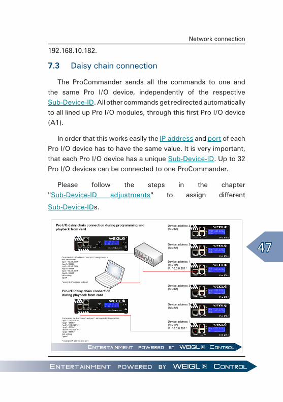
7.3 Daisy chain connection
The ProCommander sends all the commands to one and the same Pro I/O device, independently of the respective Sub-Device-ID. All other commands get redirected automatically to all lined up Pro I/O modules, through this first Pro I/O device (A1).
In order that this works easily the IP address and port of each Pro I/O device has to have the same value. It is very important, that each Pro I/O device has a unique Sub-Device-ID. Up to 32 Pro I/O devices can be connected to one ProCommander.
Please follow the steps in the chapter "Sub-Device-ID adjustments" to assign different
Sub-Device-IDs.
Pro I/O daisy chain connection during programming and playback from card
Pro-I/O daisy chain connection during playback from card
Device address 1(!ssi1#)IP: 10.0.0.201*
Device address 2(!ssi2#)
Device address 3(!ssi3#)
Device address 1(!ssi1#)IP: 10.0.0.201*
Device address 2(!ssi2#)
Device address 3(!ssi3#)
Commands for IP-address* and port* assignments in ProCommander:!spi1=10.0.0.201#!spp1=5559#!spi2=10.0.0.201#!spp2=5559#!spi3=10.0.0.201#!spp3=5559#List setting:!gpa#
*example IP address and port
Commands for IP-address* and port* settings in ProCommander:!spi1=10.0.0.201#!spp1=5559#!spi2=10.0.0.201#!spp2=5559#!spi3=10.0.0.201#!spp3=5559#List setting:!gpa#
*example IP address and port

48
Network connection
ATTENTION!
For a higher resolution, please download the wiring diagram from Weigl Support and Solutions Center!
Another possible wiring is to connect the ProCommander with the first Pro I/O device directly via network and then to daisy chain all Pro I/O modules via the WEM-NET connector IN/OUT.
ATTENTION!
This is the only option to be able to connect the ProCommander 1 (WEMC-1) and the ProCommander ES with Pro I/O devices!
As long as no device is connected to the network, which has difficulties with broadcast commands, the factory settings of the IP address and port can be used, only the Sub-Device-ID has to be adjusted.
If an explicit IP addressing is necessary, the intern chart of the ProCommander can be adjusted with the command !sdi...#.
For example the IP address 192.168.10.201 is needed, therefore the command reads as followed !sdi192.168.10.201#.
In this case all commands for the Pro I/O devices will be sent independently of the Sub-Device-ID to the first Pro I/O module with the IP address 192.168.10.201. It is important, that the

49
Network connection
first module has the Sub-Device-ID 1. Because only this device passes all commands on to the other Pro I/O modules.

50
Network connection

51
Appendix
8 Appendix8.1 Measurements
8.1.1 Pro I/O Analog 8, Pro I/O Digital 32, Pro I/O Digital Positive Output, Pro I/O Relay 8 & Pro I/O Servo
H: 41 mm 1.61 in
B: 105 mm 4.13 in
T: 103 mm 4.06 in
0,3 kg 0.66 lb

52
Appendix
8.1.2 Pro I/O DMX 512
H: 42 mm 1.65 in
B: 105 mm 4.13 in
T: 107 mm 4.21 in
0,3 kg 0.66 lb

53
Appendix
8.1.3 Pro I/O DB37 & Pro I/O CAN
H: 41 mm 1.61 in
B: 105 mm 4.13 in
T: 111 mm 4.37 in
0,3 kg 0.66 lb

54
Appendix
8.2 Electrical and operating requirements
Operating temperature: -5°C to 50°C (23°F to 122°F)
Relative humidity: 0% to 90% non condensing
Operating altitude: tested up to 2.700m (9,000 ft)
ATTENTION!
Exceeding this limits will reduce the life time of the product.

55
Appendix
8.3 Pin assignment Pro I/O Analog 8
Connector Analog Out
1 Analog-Out 1, max. 50mA
2 Analog-Out 2, max. 50mA
3 Analog-Out 3, max. 50mA
4 Analog-Out 4, max. 50mA
5 Analog-Out 5, max. 50mA
6 Analog-Out 6, max. 50mA
7 Analog-Out 7, max. 50mA
8 Analog-Out 8, max. 50mA
9 Power-Supply +, 15V-18V
10 GND
ATTENTION!
Disconnect power, before opening or closing internal jumpers!

56
Appendix
8.4 Pin assignment Pro I/O Digital 32
8.4.1 Open-Collector 1-8/ Open-Collector 9-16
Connector Upper row Lower row
1 Open-Collector 1, max. 300mA/24V
Open-Collector 9, max. 300mA/24V
2 Open-Collector 2, max. 300mA/24V
Open-Collector 10, max. 300mA/24V
3 Open-Collector 3, max. 300mA/24V
Open-Collector 11, max. 300mA/24V
4 Open-Collector 4, max. 300mA/24V
Open-Collector 12, max. 300mA/24V
5 Open-Collector 5, max. 300mA/24V
Open-Collector 13, max. 300mA/24V
6 Open-Collector 6, max. 300mA/24V
Open-Collector 14, max. 300mA/24V
7 Open-Collector 7, max. 300mA/24V
Open-Collector 15, max. 300mA/24V
8 Open-Collector 8, max. 300mA/24V
Open-Collector 16, max. 300mA/24V
9 Power-Supply +, 12V-24V
Power-Supply +, 12V-24V
10 GND GND

57
Appendix
8.4.2 Open-Collector 17-24/ Open-Collector 25-32
Connector Upper row Lower row
1 Open-Collector 17, max. 300mA/24V
Open-Collector 25, max. 300mA/24V
2 Open-Collector 18, max. 300mA/24V
Open-Collector 26, max. 300mA/24V
3 Open-Collector 19, max. 300mA/24V
Open-Collector 27, max. 300mA/24V
4 Open-Collector 20, max. 300mA/24V
Open-Collector 28, max. 300mA/24V
5 Open-Collector 21, max. 300mA/24V
Open-Collector 29, max. 300mA/24V
6 Open-Collector 22, max. 300mA/24V
Open-Collector 30, max. 300mA/24V
7 Open-Collector 23, max. 300mA/24V
Open-Collector 31, max. 300mA/24V
8 Open-Collector 24, max. 300mA/24V
Open-Collector 32, max. 300mA/24V
9 Power-Supply +, 12V-24V
Power-Supply +, 12V-24V
10 GND GND
ATTENTION!
Always mount flyback diodes in reverse direction parallel to each inductive load! Disconnect power, before opening or closing internal jumpers!

58
Appendix
8.5 Pin assignment Pro I/O Digital 32 Positive Output (PNP)
8.5.1 Open-Collector 1-8/ Open-Collector 9-16
Connector Upper row Lower row
1 Open-Collector 1, max. 2A/24V
Open-Collector 9, max. 2A/24V
2 Open-Collector 2, max. 2A/24V
Open-Collector 10, max. 2A/24V
3 Open-Collector 3, max. 2A/24V
Open-Collector 11, max. 2A/24V
4 Open-Collector 4, max. 2A/24V
Open-Collector 12, max. 2A/24V
5 Open-Collector 5, max. 2A/24V
Open-Collector 13, max. 2A/24V
6 Open-Collector 6, max. 2A/24V
Open-Collector 14, max. 2A/24V
7 Open-Collector 7, max. 2A/24V
Open-Collector 15, max. 2A/24V
8 Open-Collector 8, max. 2A/24V
Open-Collector 16, max. 2A/24V
9 Power-Supply + Power-Supply +
10 GND GND

59
Appendix
8.5.2 Open-Collector 17-24/ Open-Collector 25-32
Connector Upper row Lower row
1 Open-Collector 17, max. 2A/24V
Open-Collector 25, max. 2A/24V
2 Open-Collector 18, max. 2A/24V
Open-Collector 26, max. 2A/24V
3 Open-Collector 19, max. 2A/24V
Open-Collector 27, max. 2A/24V
4 Open-Collector 20, max. 2A/24V
Open-Collector 28, max. 2A/24V
5 Open-Collector 21, max. 2A/24V
Open-Collector 29, max. 2A/24V
6 Open-Collector 22, max. 2A/24V
Open-Collector 30, max. 2A/24V
7 Open-Collector 23, max. 2A/24V
Open-Collector 31, max. 2A/24V
8 Open-Collector 24, max. 2A/24V
Open-Collector 32, max. 2A/24V
9 Power-Supply + Power-Supply +
10 GND GND
ATTENTION!
Disconnect power, before opening or closing internal jumpers!

60
Appendix
8.6 Pin assignment Pro I/O DMX 512
8.6.1 DMX-OUT
Connector Function
Pin 1 GND
Pin 2 DMX-OUT -
Pin 3 DMX-OUT +
Pin 4 N.C.
Pin 5 N.C.
N.C. = not connected.
Connector Function
Pin 1 GND
Pin 2 DMX-OUT -
Pin 3 DMX-OUT +

61
Appendix
8.6.2 DMX-IN
Connector Function
Pin 1 GND
Pin 2 DMX-IN -
Pin 3 DMX-IN +
Pin 4 N.C.
Pin 5 N.C.

62
Appendix
8.7 Pin assignment Pro I/O Relay 8
Connector Relay 1-4 Relay 5-8
1 Relay 1 A Relay 5 A
2 Relay 1 B Relay 5 B
3 Relay 2 A Relay 6 A
4 Relay 2 B Relay 6 B
5 Relay 3 A Relay 7 A
6 Relay 3 B Relay 7 B
7 Relay 4 A Relay 8 A
8 Relay 4 B Relay 8 B
9 Power-Supply +, 12V-24V
Power-Supply +, 12V-24V
10 GND GND
ATTENTION!
Connection of internal relays max. 3A/48V!

63
Appendix
8.8 Pin assignment Pro I/O Remote 16
Connector Remote 1-8 Remote 9-16
1 Input 1 Input 9
2 Input 2 Input 10
3 Input 3 Input 11
4 Input 4 Input 12
5 Input 5 Input 13
6 Input 6 Input 14
7 Input 7 Input 15
8 Input 8 Input 16
9 Power-Supply +, 12V-24V
Power-Supply +, 12V-24V
10 GND GND
ATTENTION!
Disconnect power, before opening or closing internal jumpers!

64
Appendix
8.9 Pin assignment Pro I/O Servo
8.9.1 Servo Power
Connector Servo Power
1 Power Supply +, 5V-12V
2 GND
8.9.2 Servo 1-8
Connector Servo 1-8
1 Pulse 1-8
2 Power-Supply +, 5V-7V
3 GND

65
Appendix
8.9.3 RS485
Connector RS485
1 GND
2 DATA -
3 DATA +
4 Servo Power +
ATTENTION!
Disconnect power, before opening or closing internal jumpers!

66
Appendix
8.10 Pin assignment Pro I/O CAN
Connector Relay 1-4
1 max. +24 VDC
2 CAN-LOW
3 GND
4 N.C.
5 N.C.
6 GND
7 CAN-HIGH
8 N.C.
9 max. +24 VDC
Shield GND
N.C. = not connected.

67
Glossar
9 GlossarSub-Device-ID
Device address. Each device has its own device address it is required to issue commands, which are sent to a device to be handled correctly.

68
Glossar

69
F.A.Q.
10 F.A.Q.Why should I run a Firmware Update on my Weigl device?
Please do so, if you want that your Weigl device is capable of all the latest features and able to interpret the new ASCII commands correctly, which have been developed lately.
Even though I've read the manual, I still have questions what can I do next?
Please check out our Weigl Support and Solutions Center. There you can submit a ticket or browse through our latest solutions.
Where do I find the latest Firmware Updates, technical documentations, video trainings and other F.A.Q.?
Please check out our Weigl Support and Solutions Center.
Is there any easy way to be informed automatically if a new Firmware Update is available?
You can subscribe our Twitter account WeiglSupport.

70
F.A.Q.

71
Index
11 Index
AAppendix .................................. 51
CCE DECLARATION OF CONFORMITY ........................... 13Configuration ............................ 31
Configuration via configurator ........................... 31Firmware update ................... 34Firmware update via batch-file .......................................... 38USB port configuration ........ 31
EElectrical and operating requirements ............................ 54ETHERNET ................................ 17
FF.A.Q. ........................................ 69FCC and CE Compliance .......... 10FCC DECLARATION OF CONFORMITY ........................... 12FCC Instruction to User ........... 10Firmware update ........................... See Configuration
Firmware update via batch-file See Configuration
Front .......................................... 17Daisy chain connection ............. 19, 21, 23, 25, 26, 47
WEMC-Dio32 19, 21, 23, 25, 26FRONT............. See Pin assignment
GGlossary .................................... 67
IImportant Information and Safety Tips ............................................. 7
MMeasurements .......................... 51
Pro I/O Analog 8 ................... 51Pro I/O CAN .......................... 53Pro I/O DB37 ......................... 53Pro I/O Digital 32 .................. 51Pro I/O Digital Positive Output ................................... 51Pro I/O DMX 512 .................. 52Pro I/O Relay 8 ...................... 51Pro I/O Servo ........................ 51
NNET-IN ....................................... 17NET-OUT ................................... 17
PPin assignment ......................... 60
Pro I/O Analog 8 ................... 55Pro I/O CAN .......................... 66Pro I/O Digital 32 .................. 56Pro I/O Digital 32 Positive Output (PNP) ......................... 58Pro I/O DMX 512 .................. 60Pro I/O Relay 8 ...................... 62Pro I/O Remote 16 ................ 63

72
Index
Pro I/O Servo ........................ 64Pin Assignment FRONT ........... 17
RRear ........................................... 19
Pro I/O Analog 8 ................... 19Pro I/O CAN .......................... 26Pro I/O Digital 32 .................. 20Pro I/O Digital 32 Positive Output ................................... 21Pro I/O DMX 512 .................. 22Pro I/O Relay 8 ...................... 23Pro I/O Remote 16 ................ 24Pro I/O Servo ........................ 25
SSub-Device-ID ........................... 67
UUSB ........................................... 18USB – driver installation .......... 27
WWarranty ................................... 15