week 3.2 vhdl - pami.uwaterloo.capami.uwaterloo.ca/~basir/ece124/week3-2.pdf · ece124 digital...
TRANSCRIPT

WEEK 3.2 VHDL
ECE124 Digital Circuits and Systems Page 1
What Is VHDL (IEEE Standard 1076)?
VHDL is an acronym that stands for VHSIC Hardware DescripKon Language.
The acronym VHSIC in turn stands for Very‐High Speed Integrated Circuit program.
Program sponsored by US Department of Defense (DOD) with the goal of developing a new generaKon of high‐speed circuits.
Increasing complexity of digital circuit design required a standardized representa3on of digital circuits to that they could be shared between different designers.
Standard representaKon became a digital circuit language.
The language became the IEEE Standard 1076‐1987. New features added later and forms the IEEE Standard 1076‐1993.
ECE124 Digital Circuits and Systems Page 2

VHDL vs. convenKonal programming languages
a convenKonal programming language such as C, Pascal or Java describes a sequence of steps on how to perform a computaKon.
VHDL, on the other hand, is a language for describing a digital system.
The descripKon of a digital system can be used in many different ways:
For simula3ng the behavior of a system without building it.
For synthesis of an actual implementaKon of a system.
So, VHDL is somewhat generic in that although we are using it for digital systems, it does not specifically rely on any underlying implementaKon technology.
ECE124 Digital Circuits and Systems Page 3

SimulaKon and synthesis
Simula3on using a VHDL Simulator takes a VHDL descripKon and executes the descripKon to mimic the behavior of the circuit in terms of events and waveforms.
Different alternaKve designs can be formulated and analyzed.
Can determine performance and correctness of a design without building it.
Synthesis using a VHDL Compiler takes a VHDL descripKon to generate a physical implementaKon of a circuit.
The compiler must infer hardware structures necessary to implement the behavior described by the VHDL.
ECE124 Digital Circuits and Systems Page 4

First look at VHDL
abc
s
z
ECE124 Digital Circuits and Systems Page 5
We can get an idea of how we can use VHDL to describe digital systems if we try to draw an analogy between VHDL and a schemaKc.
Consider the following circuit (schemaKc) implemenKng a two simple logic funcKons:

The VHDL
abc
s
z
ECE124 Digital Circuits and Systems Page 6
The following is a VHDL descripKon of the previous circuit:
-- VHDL code for First Look library ieee; use ieee.std_logic_1164.all; entity FullAdder is port( a,b,c : in std_logic; s,z : out std_logic); end FullAdder; architecture prototype of FullAdder is begin s <= a xor b xor c; -- equation for s z <= (a and b) or (a and c) or (b and c); -- equation for z end prototype;
We can simulate the design using a VHDL Simulator to test correct funcKonality or we can synthesis the design to get a circuit (in some technology).

ECE124 Digital Circuits and Systems Page 7
SimulaKon of example

Delays…
abc
s
z
2
2
2
2
2
ECE124 Digital Circuits and Systems Page 8
Just a reality check… Real circuits with gates have delays. Using VHDL, you an also specify delays.
-- VHDL code for First Look library ieee; use ieee.std_logic_1164.all; entity FullAdder is port( a,b,c : in std_logic; s,z : out std_logic); end FullAdder; architecture prototype of FullAdder is begin s <= a xor b xor c after 2 ns; -- equation for s z <= (a and b) or (a and c) or (b and c) after 4 ns; -- equation for z end prototype;

ECE124 Digital Circuits and Systems Page 9
SimulaKon of example with delays

ECE124 Digital Circuits and Systems Page 10
Structure of a VHDL descripKon
We can look at the VHDL code to understand the syntax.
-- VHDL code for First Look library ieee; use ieee.std_logic_1164.all; entity FullAdder is port( a,b,c : in std_logic; s,z : out std_logic); end FullAdder; architecture prototype of FullAdder is begin s <= a xor b xor c; -- equation for s z <= (a and b) or (a and c) or (b and c); -- equation for z end prototype;

ECE124 Digital Circuits and Systems Page 11
Comments
We can have comments in a VHDL DescripKon just like in a computer program.
The can be on a line by themselves, or acer other VHDL syntax.
Comments are preceded by a double dash.
Our VHDL Descrip3on has several comments.

ECE124 Digital Circuits and Systems Page 12
Design enKKes and design architectures
The VHDL descripKon of a circuit is called a design en3ty and consists of two main parts:
En3ty declara3on.
Architecture defini3on.
The en3ty declara3on describes the interface to the rest of the world; i.e., the inputs and outputs of the circuit.
The architecture defini3on describes one par3cular implementa3on of the circuit.

ECE124 Digital Circuits and Systems Page 13
Data objects and signals
VHDL stores informaKon via data objects.
We can have three types of data objects: Signals. Constants. Variables.
We will mostly be concerned with signals.
We can think of signals as the wires in our circuit.
ECE124 Digital Circuits and Systems Page 14
Naming convenKons
Signals have names and we must adhere to the VHDL naming convenKon.
Signal names can contain any alpha‐numeric characters and the underscore.
RestricKons on signal names:
Must begin with a lefer. Can’t have two successive underscores. Can’t end with an underscore. Can’t be a VHDL reserved word. CASE INSENSITIVE.
In our example, we have 5 signals: a, b, c, s and z.
Data objects have types (we will consider this later, but in our example all signals are type std_logic).

ECE124 Digital Circuits and Systems Page 15
Signal declaraKons
Like variables in a computer program, signals need to be declared.
Signals can be declared inside three places in a VHDL DescripKon:
Port of an EnKty DeclaraKons.
DeclaraKons secKon of an Architecture DescripKon.
DeclaraKons secKon of a Package.
We will consider declaraKons in these different places later.
In our example, our 5 signals are declared inside of the Port of the En3ty Declara3on.

EnKty declaraKon syntax
EnKty DeclaraKons have a specific syntax:
ENTITY en3ty_name IS PORT(
SIGNAL signal_name : mode type ; SIGNAL signal_name : mode type ; … SIGNAL signal_name : mode type ) ;
END en3ty_name;
EnKty DeclaraKons have a name and a port. The port basically is where the inputs and outputs of the circuit are listed.
ECE124 Digital Circuits and Systems Page 16

ECE124 Digital Circuits and Systems Page 17
Architecture definiKon syntax
Architecture DefiniKons have a specific syntax:
ARCHITECTURE architecture_name OF en3ty_name IS ‐‐ declara3ve sec3on [SIGNAL declara3ons] [CONSTANT declara3ons] [TYPE declara3ons] [COMPONENT declara3ons] [ATTRIBUTE declara3ons]
BEGIN ‐‐ implementa3on [COMPONENT instan3a3on statements] [CONCURRENT ASSIGNMENT statements] [PROCESS statements] [GENERATE statements]
END architecture_name ;
We will worry about the different secKons and possibiliKes as we need them.

Operators
We can have operators in VHDL DescripKons:
Boolean Operators AND, OR, NOT, XOR, NAND, NOR, etc...
RelaKonal Operators = (equality), /= (not equality), < (less than), > (greater than), etc…
ArithmeKc Operators +, ‐, &, *,/,**,etc.
ECE124 Digital Circuits and Systems Page 18

Concurrent signal assignment syntax
We need to be able to assign values to signals.
One way of accomplishing this is via a concurrent signal assignment “<=“.
Concurrent signal assignments have the syntax:
Signal_name <= expression ;
In our example, we have 2 concurrent signal assignments in order to assign the outputs to s and z.
ECE124 Digital Circuits and Systems Page 19

ECE124 Digital Circuits and Systems Page 20
Concept of concurrency (1)
VHDL is intended to describe the behavior of digital hardware systems.
In digital hardware systems, things operate in parallel.
So, unlike a convenKonal programming language like C, Pascal or Java, we need to understand that in VHDL the order of assignments is not important; i.e., we program with the noKon of concurrency.
E.g., all concurrent signal assignments operate in parallel, and all lec‐hand sides (new values at Kme t+Δ t) get undated from the right‐hand sides using the values at Kme t.

Concept of concurrency (2)
So, in our example, the following VHDL descripKons are equivalent (order of s and z reversed).
ECE124 Digital Circuits and Systems Page 21
library ieee; use ieee.std_logic_1164.all; entity FullAdder is port( a,b,c : in std_logic; s,z : out std_logic); end FullAdder; architecture prototype of FullAdder is begin s <= a xor b xor c; z <= (a and b) or (a and c) or (b and c); end prototype;
library ieee; use ieee.std_logic_1164.all; entity FullAdder is port( a,b,c : in std_logic; s,z : out std_logic); end FullAdder; architecture prototype of FullAdder is Begin z <= (a and b) or (a and c) or (b and c); s <= a xor b xor c; end prototype;

Concept of concurrency (3)
The following ordering of signals is also equivalent (noKce that in this example, one signal on the lec‐hand side depends on the other…)
ECE124 Digital Circuits and Systems Page 22
library ieee; use ieee.std_logic_1164.all; entity Concurrent is port( a,b,c : in std_logic; d,e : inout std_logic); end Concurrent; architecture prototype of Concurrent is begin e <= c or d after 2 ns; d <= a and b after 2 ns; end prototype;
library ieee; use ieee.std_logic_1164.all; entity Concurrent is port( a,b,c : in std_logic; d,e : inout std_logic); end Concurrent; architecture prototype of Concurrent is Begin d <= a and b after 2 ns; e <= c or d after 2 ns; end prototype;
ECE124 Digital Circuits and Systems Page 23
Signal modes (1)
When declared inside of the port of an enKty declaraKon, we must give the signal a mode.
The mode can be 1 of 4 values and basically tells us the direcKon of the signal.
IN ‐‐ Data flows along the signal into the circuit.
OUT ‐‐ Data flows along the signal out of the circuit.
BUFFER ‐‐ Data flows along the signal out of the circuit, but is used internally inside of the
circuit. INOUT ‐‐
Data flows along the signal both into and out of the circuit.

ECE124 Digital Circuits and Systems Page 24
Signal modes (2)
IN
IN
ININ
OUT
BUFFER
INOUT
OUT
Signal types
Signals must have a type.
Consider real wires in a digital circuit. The logical values 0 and 1 are represented by voltages, and are not sufficient: What if a signal is not driven to a certain value because a wire is disconnected or
temporarily disconnected? What if accidentally a signal is concurrently driven to both 0 and 1… What is its
correct value? What if the iniKal value of a signal is not defined? Since signals are implemented physically with wires, how can we represent the
strength of a signal?
In the early days of VHDL, different tool vendors had their own ways to represent the above situaKons. This (again) made it hard to share VHDL descripKons.
ECE124 Digital Circuits and Systems Page 25

ECE124 Digital Circuits and Systems Page 26
IEEE Standard 1164 (1)
A numeric standard that afempts to establish a common ground for signal values to enable sharing of VHDL descripKons.
Approved a 9‐valued system:
Note: from the perspec3ve of synthesis, the 9‐valued system is slightly different than for simula3on. E.g., when circuits are synthesized unknown or un‐ini3alized values do not have any meaning – no physical representa3on for such situa3ons.

IEEE Standard 1164 (2)
A signal type std_ulogic following this standard is defined as follows:
type std_ulogic is ( ‘U’, ‐‐ Unini3alized ‘X’, ‐‐ Forcing Unknown ‘1’, ‐‐ Forcing 1 ‘0’, ‐‐ Forcing 0 ‘Z’, ‐‐ High impedance ‘W’, ‐‐ Weak Unknown ‘L’, ‐‐ Weak 0 ‘H’, ‐‐ Weak 1 ‘‐’ ‐‐ Don’t care
);
This type is defined in the IEEE library in the 1164 package (more in a minute).
ECE124 Digital Circuits and Systems Page 27

IEEE Standard 1164 (3)
Because we can have mulKple sources driving a wire, we need a resolved type. i.e., when mul3ple sources drive a wire (possibly with different values), we
need to decide on one value for the driven wire.
The IEEE 1164 Standard also defines the signal type std_logic. It has the same values as std_ulogic, determined according to the following table (if mulKple drivers).
ECE124 Digital Circuits and Systems Page 28

IEEE Standard 1164 (4)
We will see that someKmes we can have vectors of signals. We have two more types defined, namely std_ulogic_vector and std_logic_vector.
These are defined as follows (for example):
signal signal_name : std_logic_vector(7 downto 0);
Note: if std_logic_vector is a type declared in the port of an en3ty, then we also need a signal mode.
ECE124 Digital Circuits and Systems Page 29

What is a Library?
A library is a repository for frequently used design enKKes (consider a library to be much like an include file in a C program) that we wish to share.
The VHDL library IEEE; in our VHDL DescripKons simply idenKfies a library that we wish to access.
The library name is a logical name and in pracKce usually just maps to a directory on the computer in which various design units have been precompiled and stored.
ECE124 Digital Circuits and Systems Page 30

What is a Package?
A package is a design unit that contains different types of useful stuff, like definiKons of signal types, funcKons and procedures, etc… usable in our VHDL DescripKons.
The VHDL use ieee.std_logic_1164.all; means that we want to use the std_logic_1164 package which is stored inside the IEEE library.
The “.all” simply means that we want access to everything stored inside of the package.
ECE124 Digital Circuits and Systems Page 31

In Our VHDL DescripKons…
We need to idenKfy this library (IEEE) and this package (std_logic_1164) in order to use signal types std_logic and std_logic_vector in our VHDL DescripKons.
So, we always place the following VHDL prior to every en3ty declara3on.
‐‐ following lines before every VHDL en3ty declara3on. Library ieee; Use ieee.std_logic_1164.all;
ECE124 Digital Circuits and Systems Page 32

Example revisited
abc
s
z
ECE124 Digital Circuits and Systems Page 33
We should now be able to re‐examine our original VHDL DescripKon and idenKfy the meaning of every line of VHDL.
-- VHDL code for First Look library ieee; use ieee.std_logic_1164.all; entity FullAdder is port( a,b,c : in std_logic; s,z : out std_logic); end FullAdder; architecture prototype of FullAdder is begin s <= a xor b xor c; -- equation for s z <= (a and b) or (a and c) or (b and c); -- equation for z end prototype;

Another simple example (1)
ECE124 Digital Circuits and Systems Page 34
Implement the sum‐of‐products expression f = ∑(0,1,3,4,5) via a VHDL DescripKon.
Ignoring the library and use statements (just put them at the top of the VHDL descripKon), we should be able to layout the enKre VHDL DescripKon.

ECE124 Digital Circuits and Systems Page 35
Another simple example (2)
-- VHDL code for Second Simple Example library ieee; use ieee.std_logic_1164.all; entity SomeFunction is port( a,b,c : in std_logic; f : out std_logic); end SomeFunction; architecture prototype of SomeFunction is begin f <= ((not a) and (not b) and (not c)) -- m0 or ((not a) and (not b) and c) -- m1 or ((not a) and b and c) -- m3 or (a and (not b) and (not c)) -- m4 or (a and (not b) and c) ; -- m5 end prototype;
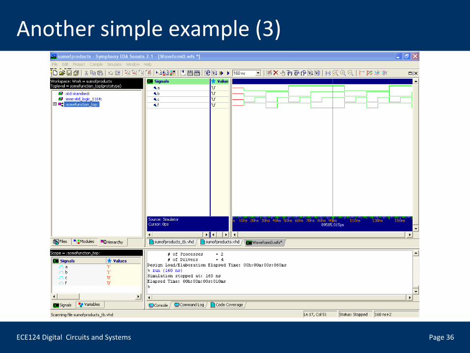
ECE124 Digital Circuits and Systems Page 36
Another simple example (3)