€¦ · web viewprovide a copy of the current mmwg procedure manual to the regional successor....
TRANSCRIPT

Eastern Interconnection Reliability Assessment Group
SC MCMMWG
Multiregional Modeling Working Group(MMWG)
Procedural Manual
Version 10

Version History
Original: November 8, 2007
Version 2: April 10, 2008
Version 3: October 28, 2008
Version 4: May 6, 2009
Version 5: May 6, 2010
Version 6: October 27, 2011
Version 7: June 6, 2012
Version 8: November 26, 2012
Version 9: April 19, 2013
Version 10: July 10, 2013
ForewordThis manual, developed by the Eastern Interconnection Reliability Assessment Group (ERAG) Multiregional Modeling Working Group (MMWG), provides the background and purpose of the Group, lists the guidelines and procedures adopted by the Group, and is intended to be a ready reference for each participant. This manual will be revised as needed to meet the needs of MMWG. The MMWG Procedural Manual is intended to minimize problems and delays in this time-critical effort. This manual is for use by the Regions and the MMWG Coordinator for the purpose of creating and maintaining the power flow base case series and creating and maintaining the System Dynamics Database (SDDB) and dynamics simulation cases, which are to be used to evaluate the dynamic performance of the systems of the Eastern Interconnection. Although references are made to internal Regional activities for the MMWG effort, this manual is only intended to be a reference for activities between Regional representatives (including liaisons) and the MMWG Coordinator.
The MMWG Coordinator and most Regional member utilities employ Siemens Power Technologies Inc. (PTI) Power System Simulator (PSSTME) software. Consequently, the various activities in the procedural manual incorporate PTI's procedures and nomenclature in describing these activities.
| i
Table of Contents
1. Introduction.................................................................................................................................2
2. Purpose of the MMWG...............................................................................................................3
3. MMWG Scope.............................................................................................................................4
3.1. Background.......................................................................................................................43.2. Scope of Activities............................................................................................................43.3. Representation..................................................................................................................53.4. Costs.................................................................................................................................53.5. Reporting..........................................................................................................................5
4. Duties of the MMWG..................................................................................................................6
4.1. Chairman..........................................................................................................................64.2. Vice Chairman..................................................................................................................74.3. Regional Coordinators.......................................................................................................74.4. Coordinator(s)...................................................................................................................84.5. Staff Liaisons....................................................................................................................94.6. Alternates........................................................................................................................10
5. Deliverables................................................................................................................................11
5.1. Regional Coordinators.....................................................................................................115.2. MMWG Coordinator(s)...................................................................................................11
6. Key Procedures..........................................................................................................................12
6.1. Meetings and Scheduling................................................................................................126.2. Auxiliary Data.................................................................................................................126.3. PSSE Version Acceptance Testing..................................................................................146.4. Power Flow Data Preparation and Submittal....................................................................146.5. Receiving Regional Power Flow Models.........................................................................156.6. Power Flow Model Merging............................................................................................156.7. Finalizing Power Flow Models........................................................................................166.8. Dynamics Data Preparation and Submittal.......................................................................166.9. SDDB (System Dynamics Database)...............................................................................186.10. Dynamics Simulation Case Initialization.........................................................................186.11. Finalizing Dynamic Models............................................................................................196.12. Costs...............................................................................................................................196.13. Data Retention................................................................................................................20
7. Model Release Procedure..........................................................................................................21
7.1. Introduction....................................................................................................................217.2. MMWG Dynamic Simulation Case Access.....................................................................217.3. ID Form..........................................................................................................................227.4. Non-Disclosure Agreement (NDA)..................................................................................237.5. MMWG region coordinator information..........................................................................26
8. Power Flow Modeling Requirements and Guidelines..............................................................27
8.1. Model Definition.............................................................................................................27
| ii
8.2. Guidelines.......................................................................................................................288.3. Power Flow Data Checks................................................................................................338.4. Troubleshooting/Causes of Non-convergence..................................................................35
9. Dynamics Data Submittal Requirements and Guidelines........................................................37
9.1. Power Flow Modeling Requirements...............................................................................379.2. Dynamic Modeling Requirements...................................................................................379.3. Dynamics Data Checks....................................................................................................399.4. Guidelines.......................................................................................................................409.5. Dynamics Initialization and Checking Procedure.............................................................409.6. Dynamics Case Acceptance Criteria................................................................................439.7. Additional Dynamics Information...................................................................................44
APPENDIX I. Master Tie Line File Data Fields................................................................................45
APPENDIX II. Utilized Impedance Correction Tables.....................................................................48
APPENDIX III. Utilized DC Lines.....................................................................................................49
APPENDIX IV. Number Range Assignments....................................................................................51
APPENDIX V. System Codes for Power Flow Data..............................................................................52
| iii

1. Introduction
The MMWG includes direct representation from the Regions in the Eastern Interconnection as well as working group power flow and dynamics coordinator(s), liaison representatives of the North American Electric Reliability Corporation (NERC) and the Federal Energy Regulatory Commission (FERC) staff, and corresponding representatives from the Electric Reliability Council of Texas (ERCOT) and Western Electricity Coordinating Council (WECC) Regions. The ERAG Management Committee (MC) appoints the Chairman and Vice Chairman for two-year terms. The Group is charged with the responsibility for developing and maintaining a series of power flow and dynamics base cases for the benefit of ERAG members. These cases are archived at ERAG and may be obtained by following the Model Release Procedure in section 7.
The MMWG assignment evolved from the efforts of various study groups to develop power flow base case models, which would realistically simulate steady-state bulk electric system behavior. The power flow base case models, which were developed by these study groups, provided a detailed representation of the study area with an equivalent representation for the surrounding network. Each of these groups developed models which were tailored to satisfy their own requirements. A substantial duplication of effort existed in data gathering and the resultant network representations were at times inadequate. Following the formation of the Regional Councils during the late 1960s, a need arose to develop expanded power flow base case models containing multi-system representation on a much broader scale than anything previously developed.
A breakthrough in multi-party base case model development effort was achieved by the development of a technique to merge selected portions of two or more power flow models, creating an expanded model. This development, in combination with the establishment of a common format for exchange of solved power flow data, enabled each group of systems to function independently when preparing a power flow model. The model, which could be created by combining these independently developed network simulations, was limited only by the size of the available computer programs.
These methods are utilized to develop the MMWG power flow models. A series of power flow cases is created annually for selected years and seasons within the planning horizon. Each case reflects the recently forecasted load at each node or bus on the interconnected system, the branches (lines and transformers) linking buses, the generating units available to supply the load, and the patterns of generation and interchange determined by economics and maintenance within the constraints of available capacity.
Increased demands on generating and transmission systems result in a need for a better understanding of system dynamic response. As a result of the interconnection between power systems, disturbances which occur on one system may affect the operation of interconnected systems. In order to properly simulate the behavior of the Eastern Interconnection it is necessary to develop and maintain representative dynamics simulation cases of the system using detailed data and to utilize widely available dynamic simulation software.
The Regional Coordinators are responsible for submitting the dynamics data for their member systems along with the corresponding inserts for the MMWG power flow cases which permit the dynamics data to be linked to the power flow cases. The MMWG Dynamics Coordinator represents the contractor who receives the dynamics data and power flow cases from which the SDDB is updated and dynamics simulation cases are created. Dynamics cases are also created annually.
| iv

2. Purpose of the MMWG
The purpose of MMWG is to coordinate, in a timely manner, the development of designated power flow and dynamics simulation base case models that realistically simulate steady state and dynamic bulk electric system behavior. To achieve this purpose, MMWG has established a set of common objectives and timetables for data submission. Generally, MMWG develops a series of operating and planning power flow and dynamics simulation models for the use of ERAG members for reliability and transfer capability studies.
Of paramount importance in this effort is the detail in which the various systems are modeled. The detail included in each system model must be adequate for all interregional and intraregional study activities but not necessarily as detailed as required for internal studies. This means that each system model should include sufficient detail to ensure that power transfers or contingencies can be realistically simulated. Consideration of program limitations and other factors may inhibit each system from including a fully detailed representation at all voltage levels. However, any principal bulk electric facility that may be adversely affected by a contingency in another system should be included.
The series of base case models will be updated annually to assure that each model contains the best available data for the time period modeled. Anyone conducting a study may find it necessary to represent local system conditions and facilities in more detail, but substantial updating of other systems at the time of use should not be required. It is also expected that a Regional or interregional study group will update the study area to incorporate changes in system plans which have occurred since the data for MMWG model was assembled.
In order to accurately simulate the performance of the interconnected electric systems, detailed rather than classical dynamics models are utilized. Standard PSSTME models shall be used, except as noted below, to make the database as widely useable as possible. User defined models may be utilized when the response cannot be represented by a standard PSSTME model. Models are included of all equipment that significantly influences the performance of the bulk power system. The objective is to provide interregional dynamics databases and dynamics simulation cases that can be used to accurately evaluate the performance of the Eastern Interconnection.
| v
3. MMWG Scope
3.1. Background
Many electric systems are experiencing increased loadings on portions of their transmission systems, which can, and sometimes do, lead to lightly damped, low frequency (0.2-0.8 Hz) inter-area oscillations. Such oscillations can severely restrict system operations by requiring the curtailment of electric power transfers. These oscillations can also lead to widespread system disturbances if cascading outages of transmission lines occur due to oscillatory power swings. It is also not uncommon for many generators throughout the interconnected systems to participate to some degree in these inter-area oscillations.
To properly capture the dynamic behavior of interconnected electric systems requires good dynamics modeling of all of the interconnected systems within state-of-the-art software capabilities. ERAG is playing a leading role in developing system representations for use in power flow and system stability studies because of the need for simulation models that cover a wide geographic area. It is not possible for an individual Region (in most cases), sub-region, power pool, or system to successfully construct an accurate system dynamics simulation model without input from other interconnected systems. ERAG's continued leadership and coordination activities in the creation and maintenance of large interconnected electric system models are important to the development of an integrated SDDB.
Many ERAG members are now faced with the need to accurately establish transmission limits--including those limits based on system stability considerations--in responding to requests from independent power producers and others for transmission services. The credibility of the databases needed to make such studies is important. Therefore, it will be essential that the stability models be developed on a coordinated basis, following well-defined procedures. ERAG is in a unique position to achieve this goal.
3.2. Scope of Activities
In carrying out the above purpose, the MMWG will:A. Establish a schedule for all case development work.B. Annually develop a series of solved power flow models of the Eastern Interconnection
for use by the Regions and their members.C. Maintain a database (SDDB) of annually updated system dynamics modeling data of the
Eastern Interconnection.D. Develop initialized dynamics simulation models of the Eastern Interconnection annually
for at least two time periods — near term and approximately five years into the future. These dynamics models shall be based on selected models from the power flow model series.
E. Annually review the power flow base case and system dynamics simulation model requirements of the Eastern Interconnection Regions and recommend power flow and system dynamics models to be developed.
F. Maintain a Procedural Manual for use by the Regions in submitting power flow and system dynamics modeling data, and for use by the MMWG Coordinators in developing power flow and dynamics simulation models.
G. Work with the Regions and the ERAG staff to coordinate and ensure the timely submission of regional and member system data.
| vi

H. Keep abreast of the modeling requirements of the Regions and member systems and adopt or develop improved modeling and data handling techniques as required.
I. Keep abreast of state-of-the-art techniques and evaluate alternative methods and software for developing the MMWG series of solved power flow models and the initialized system dynamics simulation models.
3.3. Representation
The MMWG membership shall be comprised of one power flow representative and one dynamics representative from each of the Eastern Interconnection Regions and non-voting representatives as follows: one liaison representative each from the ERCOT and WECC Regions, a coordinator from each of the organizations that provides model development services to MMWG, and a NERC and FERC staff liaison. Each Region shall have one vote. One or more alternate representatives from each Eastern Interconnection Region may be added at the discretion of each Region.
The MMWG Chairman and Vice Chairman are to be appointed by the MC Chairman from among the Eastern Interconnection Regional representatives for a two-year term. The Vice Chairman should be available to succeed to the chairmanship.
3.4. Costs
The cost of MMWG activities will be shared among the Regions in the Eastern Interconnection and will be administered by the ERAG staff. The costs will be reported to the ERAG Management Committee at least annually.
3.5. Reporting
The MMWG Chairman will report periodically to the ERAG Management Committee on assignments from the Management Committee, recommendations requiring Management Committee approval, and other MMWG activities.
| vii

4. Duties of the MMWG
4.1. Chairman
The chairman is selected from among the Regional Coordinators and appointed by the MC Chairman to a two-year term. The principal function of the Chairman is to provide a two-way communication channel between the MC and the MMWG. The specific duties of the Chairman are:A. Report periodically to the MC on assignments from the MC, recommendations requiring
MC approval, and other MMWG activities.B. Present any recommended changes to the basic MMWG power flow model development
schedule to the MC for review and approval. Present and recommend changes to the basic SDDB and dynamics simulation model development schedule to the MC for review and approval.
C. Present the MMWG case development schedule to the MC for review and approval.D. Provide the MC with status reports at its regular meetings on the progress of the model
development effort, and the progress of the SDDB and dynamics simulation models development efforts.
E. At each regular meeting of the MC, the Chairman reports on the status of the current MMWG model development work, the expected completion date of the effort, and any problems being encountered.
F. The Chairman also reports on other matters relating to the current and future work of the MMWG. A written report is provided to the MC as part of its meeting agenda background materials.
G. Proposals to the MC for new models to be developed.H. From time to time, individual Regions will propose to the MC that certain special power
flow models be developed, such as a light load model. Regions may also suggest modifying the regular schedule of model development to include new models. Such proposals are considered and, if approved by the MC, are referred to the MMWG, through the Chairman, for scheduling. The MMWG evaluates the proposal and establishes a specific schedule for model development that the MMWG determines it can meet.
I. MMWG proposals for new models or other database development work.J. The MMWG may identify the need for some change in the regular array of models to be
developed or for some other database development effort. When this occurs, the Chairman will present a proposal for the supplemental work to the MC for approval.
K. Work with the MMWG Dynamics Coordinator, as required, to solve problems which may arise in the SDDB and dynamics simulation model development effort.
L. During the actual model development effort, problems sometimes arise in obtaining data and information on time or in processing the data and information that are submitted. The MMWG Coordinator normally handles most of these problems, keeping the Chairman appropriately informed. However, in certain instances, the MMWG Coordinator may need specific assistance from the Chairman in solving a particular problem. The Chairman working closely with the MMWG will assist by contacting individual Regional Councils and Coordinators or by bringing the problem to the attention of the MC. If a decision is needed immediately and there is no MC meeting imminent, the Chairman will contact the MC Chairman, who will act in lieu of the MC.
| viii
4.2. Vice Chairman
The vice chairman is selected from among the Regional Coordinators and appointed by the MC Chairman to a two year term. The principal functions of the vice chairman are to assist the chairman in the performance of the chairman's duties and to serve on behalf of the chairman during the chairman's absence. The vice chairman is expected to succeed the chairman at the end of the chairman's term.
4.3. Regional Coordinators
Regional Coordinators are appointed by each of the ERAG Regional Councils. Regional Coordinators of the Regions of the Eastern Interconnection are the only voting members of the MMWG. The specific duties of the Regional Coordinators are:
A. Collect and assemble regional data for each case in the power flow series.B. Coordinate Regional interchange transaction schedules and regional tie lines for each
case. (Note: Tie line listings should be in the format approved by the MMWG; see Appendix I.) Only the changes (changes, additions, deletions) to the tie lines from the prior year's list should be submitted to the MMWG Coordinator. The tie line entries should be clearly labeled.
C. Exchange coordinated listings of regional interchange transaction schedules and regional tie line data according to the approved schedule for each case.
D. Forward solved power flow cases, interchange transaction schedules, and tie line data to the MMWG Coordinator according to the procedures in this manual and in accordance with the approved schedule.
E. Provide the MMWG Coordinator with whatever assistance is needed to solve non-convergent base case models.
F. Review the converged MMWG cases to verify proper and complete regional representation according to the approved schedule.
G. Determine the cause of any regional problem associated with creating the cases and notify the data supplier so that the problem does not reoccur.
H. Work with the regional members to coordinate and ensure the timely submission of member system data.
I. Provide assistance to the MMWG Coordinator in resolving any discrepancies between the power flow data and the SDDB.
J. Coordinate with the MMWG Coordinator to incorporate modifications to the power flow data and the SDDB.
K. Maintain the MMWG Procedural Manual for use by the Regions in submitting system dynamics data. Modify, update, and refine the procedures as needed.
L. Provide written notification to the MMWG Coordinator of all significant errors observed in any of the most recent SDDB or dynamics simulation cases.
GeneralA. Provide a copy of the current MMWG Procedure Manual to the regional successor.B. Provide current contact information to the MMWG Coordinator.C. Maintain MMWG roster.D. Appoint an alternate representative to assure continuity in MMWG activities.E. Attend all regularly scheduled meetings of the MMWG. If unable to attend, the
chairman should be notified and an alternate should attend.F. If a significant error is observed in one of the most recent final MMWG models, the
appropriate Regional Coordinator is to be notified immediately. The Regional
| ix

Coordinator of the Region with the error should notify the MMWG in writing immediately.
A. A Regional Coordinator will serve a one year term as secretary of the MMWG. The term will begin and end at the start of each calendar year. The duties of the secretary are:
1. Prepare minutes of all MMWG meetings and conference calls2. Work with chair to prepare meeting agendas3. Arrange meetings and conference call/web conferences as needed. If the secretary
does not have access to the required resources, they can coordinate resource needs with other regions.
4.4. Coordinator(s)
The MMWG Coordinator(s) represent the contractor(s) who create, update, and maintain the series of power flow and dynamics cases and the SDDB for the MMWG. The MMWG coordinator activities are divided into power flow and dynamics areas and can be handled by different contractors. The Dynamics Coordinator is required to deliver copies of the SDDB to the MMWG Regional Coordinators. Therefore, the specific database software used shall be transportable and executable on the MMWG member computer platforms that only require a purchase of an inexpensive database software package or a nominal licensing fee.
The Power Flow Coordinator is responsible for creating the power flow base case series. Included among the specific duties of the Power Flow Coordinator are the following:A. Help prepare time schedules for each MMWG function for approval by MMWG.B. Request data from Regional Coordinators and maintain the time schedule determined by
the Group for each major MMWG effort.C. Prepare and distribute progress reports to Regional representatives at regular intervals
during periods of significant MMWG activities and for each scheduled MMWG meeting.D. Apprise the MMWG Chairman of the status of the MMWG effort and the actions of the
various Regions.E. Apprise the MMWG chairman of the status of coordinator activities performed for the
MMWG.F. Contact the appropriate Regional Coordinator should any problems develop with data
sets, such as not conforming to MMWG computational facility requirements and guidelines, or requiring special processing.
G. Maintain direct supervision over the Regional Coordinators' review of the base models and take appropriate measures to expedite the successful completion of this task. Determine, with consultation if necessary, whether an additional calculation of a merged and solved case should be attempted if revisions would not affect the solution beyond a very local area.
H. Exercise direct supervision over any change made at the computational facility to any solved case.
I. Verify the data for the unique eighteen-character bus name and voltage for the following components: all generator buses, and all tie lines buses. Any discrepancies are to be returned to the Regional representatives for correction.
J. Coordinate with the Regional Coordinators and the Dynamics Coordinator to resolve any discrepancies between the power flow data and the SDDB data.
K. Coordinate with the Regional Coordinators to incorporate improvements in the power flow data.
| x

L. Provide to the MMWG the final power flow cases, only after the MMWG has approved the finalization of the cases.
M. Allocate DC Line numbers, FACTS device numbers and Transformer Correction Table numbers to the requesting Regional Coordinators.
N. Provide to the MMWG an annual final report that summarizes the efforts of the coordinator, including all modifications that were made to the MMWG power flow along with recommendations for improvements.
O. Assist the MMWG in the creation and revision of the MMWG Procedural Manual.
The Dynamics Coordinator is responsible for updating the SDDB and creating the approved dynamics simulation cases annually. Included among the specific duties of the Dynamics Coordinator are the following:
A. Help prepare time schedules for each SDDB and dynamics simulation case update.B. Request data from Regional Coordinators and maintain the time schedule determined by
the Group for each major MMWG effort.C. Prepare and distribute progress reports to Regional representatives at regular intervals
during periods of significant MMWG activities and for each scheduled MMWG meeting.D. Apprise the MMWG Chairman of the status of the MMWG effort and the actions of the
various Councils.E. Apprise the MMWG chairman of the status of coordinator activities performed for the
MMWG.F. Contact the appropriate Regional Coordinator should any problems develop with data
sets, such as not conforming to MMWG computational facility requirements and guidelines or requiring special processing.
G. Exercise direct supervision over any change made at the computational facility to any solved model.
H. Coordinate with the Regional Coordinators and the Power Flow Coordinator to resolve any discrepancies between the power flow data and the SDDB data.
I. Coordinate with the Regional Coordinators to incorporate improvements in the SDDB.J. After the MMWG has approved the dynamics cases for finalization, provide to the
MMWG the final SDDB, the power flow cases, the converted power flow cases, and the corresponding PSSTME DYDA, CONEC, and CONET files in accordance with the guidelines specified in Section 9.5 of this document.
K. Provide to the MMWG an annual final report that summarizes the efforts of the contractor, including all modifications that were made to the MMWG power flow and dynamics data along with recommendations for the SDDB improvements.
L. Assist the MMWG in the creation and revision of the MMWG Procedural Manual.
4.5. Staff Liaisons
The staff liaisons represent their organizations in the MMWG efforts, support, and coordinate with the MMWG. The MMWG will have liaisons from the following organizations: NERC, FERC, WECC, and ERCOT.
4.6. Alternates
A Region may designate one or more Alternates to the MMWG. Alternates should be included in mailing lists for distribution of MMWG correspondence and documents. Alternates may
| xi
attend and participate in MMWG meetings but shall not vote except by proxy when the Regional Coordinator is absent.
| xii

5. Deliverables
5.1. Regional Coordinators
The Regional Coordinators will provide the following to the MMWG Coordinator(s).Power Flow CasesA. Data as needed to create the MMWG power flow cases in RAWD or Saved Case format,
regional representation shall be within an entire solved MMWG power flow model in the approved PSSTME revision format
B. Tie line and interchange data in the specified formatC. IDEV or Python files for any data changesD. PSSTME formatted contingency file containing five N-1 contingencies valid for all cases
in the model series. E. Data Dictionary containing fields for Bus Number, 18 character PSSTME Bus Name, EIA
Plant Code (U.S. only), Area Number, and Non-Abbreviated Bus Name.Dynamics CasesA. Dynamics input data in DYRE format for new modelsB. SDDB Excel worksheet for changes to the databaseC. FLECS code and documentation for user defined modelsD. Load conversion CONL file sorted by areaE. List of netted generation busesF. Two contingency events per region in IDEV format
5.2. MMWG Coordinator(s)
The MMWG Coordinator(s) will post the following to a secure site:A. Power Flow Cases - Initialized steady state and regional contingency cases.
1. Power Flow SAV and RAWD case file2. Master Tie Line list3. Data Dictionary4. Interchange Schedule5. Associated Power Flow Checking files
B. Dynamics Cases - Dynamics case input data, output files and instructions including:1. Dynamics input data in DYRE format2. FLECS code for user defined models3. Load conversion CONL file sorted by area4. File containing netted generation (GNET)5. Any IPLAN or PYTHON programs necessary to set up the dynamics case
C. Complete SDDB and User Manual D. Final reports
| xiii

6. Key Procedures
6.1. Meetings and Scheduling
Two meetings are held annually with additional dates scheduled as needed. The meetings are hosted by the Regions per the rotation schedule and are typically held at the regional offices. Below are typical agenda items for each meeting
Spring MeetingAt the spring meeting, the following key items are usually included in the agenda:A. The models to be assembled in the following year are recommended, subject to approval
by the MC.B. The detailed data submittal and case finalization schedule for the current year effort is
reviewed and revised as appropriate.C. The MMWG Coordinator(s) presents a summary of the costs for the previous year’s
effort.D. An initial cost estimate is made for the upcoming case development effort for use in the
ERAG annual budget.E. The MMWG Procedural Manual is reviewed in detail.F. Any other policy matter is discussed as appropriate.
Fall MeetingAt the fall meeting, the following key items are usually included in the agenda:A. The MMWG coordinators present the status of power flow and dynamics case
development efforts concentrating on any problems.B. The MMWG Procedural Manual is reviewed as necessary.C. Any other policy matter is discussed as appropriate.
6.2. Auxiliary Data
A. Master Tie Line DatabaseThe Power Flow Coordinator maintains a Master Tie Line Database for use in the case creation process.
1. Only the interregional tie lines contained in the Master Tie Line Database will appear in the final power flow models.
2. All interregional tie bus names and tie line data should conform to the entries in the Master Tie Line Database as approved by the Regional Coordinators.
3. The Coordinator for the Region in which a tie line bus is located shall specify the bus name nomenclature that is to appear in the Master Tie Line Database and in the final MMWG models.
4. A tie line will not be represented in a particular power flow base case model unless both parties involved have agreed to include it.
5. All tie line bus names and numbers should be standard and unique within each area in all models in a case series. Changes in tie line bus names and numbers from one series to the next must be kept to a minimum to reduce changes in computer support programs.
6. The in-service date is the date that the line will be operable. The out-of-service date that the line will be inoperable. The In-service and out-of-service dates will be expressed as mm/dd/yyyy.
| xiv
7. The Power Flow Coordinator will maintain only one Master Tie Line Database per series.
8. The Regional Coordinators should only submit tie line changes (additions, deletions, and changes) from the prior year’s Master Tie Line Database to the Power Flow Coordinator. Each entry of the tie line data should be clearly labeled.
9. Data for the Master Tie Line Database should be submitted in the spreadsheet format determined by the MMWG. The data fields are specified in Appendix I.
10. Post case creation corrections to the tie line data shall only be made through the process above, and must include revisions to the Master Tie Line Database
11. Ties with an in-service/out-of-service date from 01/16/yyyy to 04/15/yyyy will be in-service/out-of-service in the spring model for the year yyyy.
12. Ties with an in-service/out-of-service date from 04/16/yyyy to 07/15/yyyy will be in-service/out-of-service in the summer model for the year yyyy.
13. Ties with an in-service/out-of-service date from 07/16/yyyy to 10/15/yyyy will be in-service/out-of-service in the fall model for the year yyyy.
14. Ties with an in-service/out-of-service date from 10/16/yyyy to 01/15/yyyy will be in-service/out-of-service in the winter model for the year yyyy.
B. Interchange Schedule Matrices1. All transactions and interchange schedules conform to tables of interchange
transaction schedules developed and agreed to by the Regional Coordinators prior to the creation of the first case in the series. The tables can include firm and non-firm interchange schedules for all cases in the MMWG power flow series. Complete interchange matrices should be submitted which include interregional (i.e. Region to Region) transactions and all area total interchange schedules. The final model area interchange value is derived from the transaction workbook.
2. Seasonal transactions should be included, starting with the first year of the MMWG Base Case Series being developed.
3. Summer interchange schedules should reflect transactions expected to be in effect on July 15th.
4. Winter interchange schedules should reflect transactions expected to be in effect on January 15th.
5. Fall interchange schedules should reflect transactions expected to be in effect on October 15th
6. Spring interchange schedules should reflect transactions expected to be in effect on April 15th
7. Light Load interchange schedules should reflect transactions expected to be in effect on April 1st
8. The schedule shall show net scheduled interchange for each Region and for each area within that Region.
9. All interchanges must net to zero for all cases.10. Any interchange schedule submitted that has an associated firm transmission
service source to sink should be labeled with an X.11. All areas should be identified with area names and numbers.12. All interchange schedules shall be integer values.
C. Transformer Impedance Correction Table – Assigned impedance correction table numbers are shown in Appendix II. When a region would like to utilize a new transformer impedance correction table, they shall contact the Power Flow Coordinator. The Power Flow Coordinator will consult the currently utilized transformer impedance
| xv

correction table list and determine if any existing tables can be used for the new transformer impedance correction table. If no current transformer impedance correction table can be used, the Power Flow Coordinator will assign the requesting region a new transformer impedance correction table number. The official Impedance Correction Table will be maintained in the Procedure Manual (Appendix II).
D. DC Circuit Names – Assigned DC circuit names are shown in Appendix III. When a region would like to use a new DC circuit name, they must contact the Power Flow Coordinator. The Power Flow Coordinator will consult the currently utilized DC circuit list and assign the requesting region a new circuit for their exclusive utilization.
E. Number Range AssignmentsArea, zone, owner, and bus number ranges assigned by the MMWG to each region are shown in Appendix IV.
F. System Codes for Power Flow DataAll areas in the series of cases shall have proper area names and numbers for identification, consistent with the designations agreed to by the MMWG (see Appendix V).
6.3. PSSE Version Acceptance Testing
A. The MMWG must not approve a new version of PSSE until the following testing of the new version has been successfully performed:1. Using a power flow case (as chosen by the MMWG) from the most recent
MMWG series, perform the following using the current PSSE version and the proposed new PSSE version and verify that both versions produce identical results:a. Power flow solution using the solution requirements in 6.7 Db. ACCC solution using the five contingencies submitted by each region from
the most recent MMWG series. c. Other testing as deemed necessary by each Regional Power Flow
Coordinator (e.g. test user-written auxiliary programs).2. Obtain updated source code for user-written dynamic models if needed for
compatibility with the proposed new PSSE version.3. Compile source code using the proposed new PSSE version. 4. Using the proposed new PSSE version, perform the dynamics testing required in
section 6.11 and 9.3 C on a single dynamics case (as chosen by the MMWG) from the most recent MMWG series.
5. Obtain confirmation from Siemens PTI that MOD, MOD File Builder, and MUST are all compatible with the proposed new PSSE version.
6.4. Power Flow Data Preparation and Submittal
A. All power flow data submitted should be in accordance with the Power Flow Modeling Guidelines contained in Section 8.2. It is the responsibility of each Regional Coordinator to ensure that the data is in the correct format.
| xvi

1. Each region is to perform an N-1 screening of its bulk electric system for the purposes of identifying modeling errors before submitting their data to the Power Flow Coordinator.
2. Overloads or voltages that exceed the region’s screening criteria should be reviewed and commented on as to whether they are resulting from modeling errors. Corrections for modeling errors should be made.a. Each region shall be able to produce the results of the review upon request.
B. Each case submitted by each region must solve via same method as the Power Flow Coordinator is obligated to use as noted in Section 6.6 “Finalizing Power Flow Models”.
C. The version of software for each series of cases will be determined by the MMWG.D. Cases shall be delivered to the Power Flow Coordinator on or before the scheduled due
date.
6.5. Receiving Regional Power Flow Models
The Power Flow Coordinator should perform the following steps with every received Regional base case model:
A. The dates of receipt are logged.B. The data are read and saved in a file for conversion to the required format used by the
Power Flow Coordinator for power flow data merging and calculation.C. Area names, area numbers, zone number ranges, and bus number ranges are checked for
compliance with those in Appendix IV.D. Non-convergent cases are reported to the responsible Regional Coordinator for corrective
action. (See Section 8.4 for causes of non-convergence.)
6.6. Power Flow Model Merging
Once all data has been received from the Regions for a specific case, the Power Flow Coordinator will merge the regional submittals into a MMWG case.A. One of TVA's Brown's Ferry generators, represented as on-line, will be the primary
swing machine for each MMWG case. Other swing machines are included in all other non-synchronous areas (currently Hydro Quebec, northern Manitoba, WECC, ERCOT).
B. Regional Coordinators shall resolve all tie line discrepancies specified by the Power Flow Coordinator within two weeks.
C. The Power Flow Database (PFDB) used by the Power Flow Coordinator to merge the cases will utilize the Master Tie Line database for all interregional tie lines. The Power Flow Coordinator will notify the responsible Regional Coordinators of any tie line insertion problems, typically due to duplicate or improperly named buses in the Regional cases.
D. The Power Flow Coordinator will check tie lines in the merged case against the MMWG Master Tie Line database. Any discrepancies will be reported to the responsible Regional Coordinators.
E. The Power Flow Coordinator will check interchange in the merged case against the MMWG Scheduled Interchange Matrices. Any discrepancies will be reported to the responsible Regional Coordinators. The sum of area interchange in the case must be zero. Also, the area interchange deviation tolerance for each area should be less than or equal to 5 MW.
F. If convergence of the merged case is not successful, the Power Flow Coordinator will notify the Regional Coordinators for corrective action. (See Section 8.4 for possible causes of non-convergence.)
| xvii

G. Successfully converged merged cases will be named in accordance with the following convention:
Year SERIES, ERAG/MMWGYear Season CASE, TRIAL n
For Example:2011 SERIES, ERAG/MMWG2012/13 WINTER PEAK CASE, TRIAL 1
6.7. Finalizing Power Flow Models
A. The Regional Coordinators will review the series of cases and provide corrections for any modeling problems according to the previously determined schedule. This fine tuning phase is not intended as an opportunity for a complete revision of the case. Extensive revision should not be required at this time because basic case deficiencies or data errors should have been corrected before the case was submitted to the MMWG.
B. To make sure that no changes were made to interregional tie lines, the Master Tie Line database should again be read into the models.
C. A case shall satisfy all Power Flow Data Checks in Section 8.3 before it can be finalized.D. A case shall solve using the Fixed Slope Decoupled Newton Solution (PSSTME activity
FDNS) and Full Newton Solution (FNSL) with the following conditions before it can be finalized:
1. Solve in less than 20 iterations (preferably in less than 10 iterations)2. Solve using the flat start option (can exceed iteration requirement above)3. Employ a 1.0 MW/MVAR per bus mismatch tolerance4. Enforce area interchange with the "Tie Lines and Loads" option.5. Enable: (1) Tap changing transformers (2) Switched shunts (3) Phase shifters (4)
DC transformer tap stepping 6. Enforce generator VAR limits in 1 iteration7. Zero impedance cutoff setting of 0.0001 p.u. 8. Solve from a hot start under first contingency conditions provided by each
Regional representative. Each Regional representative is to send all necessary information to conduct five AC N-1 contingencies (PSSTME format for .CON).
E. A case is considered final when all Regional Coordinators approve it.F. Distribution of the cases will not commence before the cases are final. Distribution will
begin within two weeks following approval. MMWG should direct the Power Flow Coordinator regarding the distribution format and media.
G. All case distributions should include associated interchange tables.
6.8. Dynamics Data Preparation and Submittal
A. Dynamics data should be prepared and submitted in accordance with Section 9 requirements and guidelines.
B. Unique bus names, base voltages, and unit id combinations submitted by Regional Coordinators should be consistent from case to case within a model series. If a bus name, base kV or unit id combination is changed, the Regional Coordinator must notify the dynamics coordinator of that change.
C. Data validation and checking using the procedures in Section 9.5 is recommended.
| xviii

D. Dynamics data and linkages should be prepared for use with the annually updated release of the MMWG power flow cases.
E. The Dynamics Coordinator shall determine the media and format used to transmit models.
F. Dynamics data and linkages to the MMWG power flow cases are to be tested for accuracy by the Regions prior to submission to the Dynamics Coordinator.
G. Dynamics data and linkages to the MMWG power flow cases are to be delivered to the Dynamics Coordinator on or before the scheduled date.
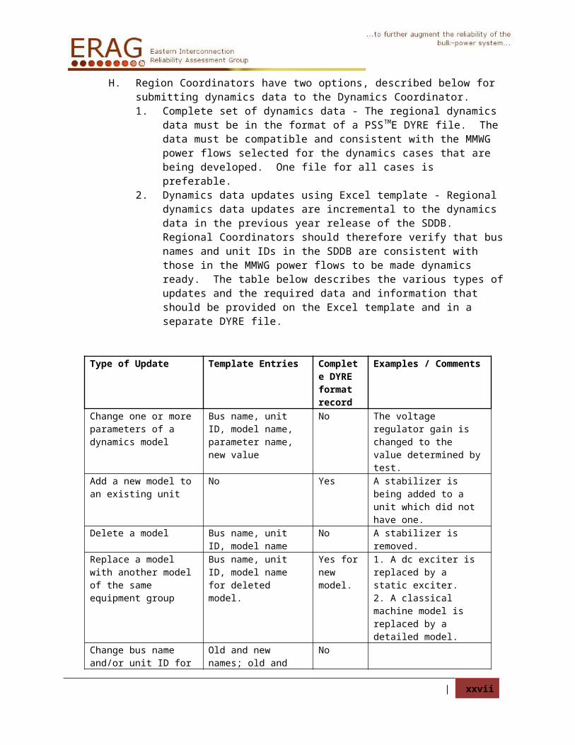
H. Region Coordinators have two options, described below for submitting dynamics data to the Dynamics Coordinator.1. Complete set of dynamics data - The regional dynamics data must be in the format
of a PSSTME DYRE file. The data must be compatible and consistent with the MMWG power flows selected for the dynamics cases that are being developed. One file for all cases is preferable.
2. Dynamics data updates using Excel template - Regional dynamics data updates are incremental to the dynamics data in the previous year release of the SDDB. Regional Coordinators should therefore verify that bus names and unit IDs in the SDDB are consistent with those in the MMWG power flows to be made dynamics ready. The table below describes the various types of updates and the required data and information that should be provided on the Excel template and in a separate DYRE file.
Type of Update Template Entries Complete DYRE format record
Examples / Comments
Change one or more parameters of a dynamics model
Bus name, unit ID, model name, parameter name, new value
No The voltage regulator gain is changed to the value determined by test.
Add a new model to an existing unit
No Yes A stabilizer is being added to a unit which did not have one.
Delete a model Bus name, unit ID, model name
No A stabilizer is removed.
Replace a model with another model of the same equipment group
Bus name, unit ID, model name for deleted model.
Yes for new model.
1. A dc exciter is replaced by a static exciter.2. A classical machine model is replaced by a detailed model.
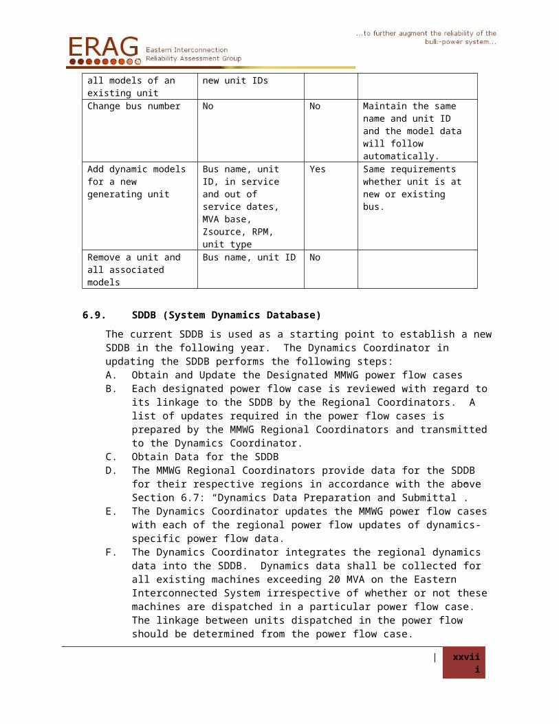
Change bus name and/or unit ID for all models of an existing unit
Old and new names; old and new unit IDs
No
Change bus number No No Maintain the same name and unit ID and the model data will follow automatically.
Add dynamic models for a new generating unit
Bus name, unit ID, in service and out of service dates, MVA base, Zsource, RPM, unit type
Yes Same requirements whether unit is at new or existing bus.
Remove a unit and all associated models
Bus name, unit ID No
| xix
6.9. SDDB (System Dynamics Database)
The current SDDB is used as a starting point to establish a new SDDB in the following year. The Dynamics Coordinator in updating the SDDB performs the following steps:A. Obtain and Update the Designated MMWG power flow casesB. Each designated power flow case is reviewed with regard to its linkage to the SDDB by
the Regional Coordinators. A list of updates required in the power flow cases is prepared by the MMWG Regional Coordinators and transmitted to the Dynamics Coordinator.
C. Obtain Data for the SDDB D. The MMWG Regional Coordinators provide data for the SDDB for their respective
regions in accordance with the above Section 6.7: “Dynamics Data Preparation and Submittal”.
E. The Dynamics Coordinator updates the MMWG power flow cases with each of the regional power flow updates of dynamics-specific power flow data.
F. The Dynamics Coordinator integrates the regional dynamics data into the SDDB. Dynamics data shall be collected for all existing machines exceeding 20 MVA on the Eastern Interconnected System irrespective of whether or not these machines are dispatched in a particular power flow case. The linkage between units dispatched in the power flow should be determined from the power flow case.
G. The Dynamics Coordinator correlates the MMWG power flow data with the dynamics models in the SDDB. This correlation determines any missing dynamic models; identifies any models in the SDDB for which there is no corresponding power flow data; and verifies correspondence of the SDDB data with machines that are out-of-service in the MMWG power flow data. Dynamics data for machines that are out-of-service shall be included in the SDDB. Any machine for which no dynamics data can be obtained shall be represented utilizing typical data or shall be netted out of the power flow in accordance with Section 9. The Dynamics Coordinator documents the power flow/dynamics discrepancies and all modifications made to resolve them. Based on the discrepancy resolution process, the Dynamics Coordinator updates the SDDB and updates the MMWG power flow cases.
H. The Dynamics Coordinator reviews the MMWG power flow data and the dynamic models and parameters to identify questionable and bad data in either. Questionable or bad data shall be documented and resolved with the Regional Coordinator, and the power flow cases and the SDDB updated as necessary.
6.10. Dynamics Simulation Case Initialization
The Dynamics Coordinator in creating dynamics simulation cases performs the following steps:A. Perform Initialization Based on DYRE, CONEC, CONET and RAWD FilesB. Read the updated power flow RAWD data into the PSSTME power flow program. Solve
the AC power flow case. After the AC solution, convert the generators and load using the CONG and CONL activities. The appropriate percentages of constant impedance, constant current, and constant P/Q loads for the CONL conversion process are provided by the Regional Coordinators. Using activities ORDR, FACT and TYSL, solve the converted power flow case. Save the converted case.
C. Obtain the DYRE file from the SDDB. For each area in the MMWG power flow case, add the PTI "TOTA" model to the DYRE file. Also, add the "SYSANG" model and the "RELANG" model to express rotor angles relative to a weighted average angle. The
| xx

outputs of these models will be used to assess the steady state stability of the dynamics simulation cases. The plots of these outputs will be required in the final report.
D. Using the PTI PSSTME dynamics simulation skeleton program, read in the solved converted power flow case. Perform activities FACT and TYSL.
E. Perform activity DYRE and read in the DYRE dynamics data file. Note and document any warning and error messages that are displayed. Run the IDEV to link parallel DC pole dynamics models (Chateauguay and Radisson-Sandy Pond). Create the CONEC and CONET files and compile command procedure before exiting the PSSTME dynamics simulation program. Resolve any problems indicated by the activity DYRE by coordinating with the appropriate Regional Coordinator.
F. Add the user-written source codes to the respective CONEC and CONET files and execute the compile command procedure previously created. Create a snapshot to be used with the PSSDS executable. Execute CLOAD4 to link the files, thereby creating a PSSDS executable.
G. Using the user PSSDS executable created, read in the solved converted power flow case. Perform activities FACT and TYSL. Perform activity STRT. Note any states that are not initializing properly, i.e., any dynamic states whose derivatives are not zero, within the standard tolerance. Document and correct, as needed, these non-initializations of states. Repeat this procedure until all initialization problems have been corrected.
H. Once all the dynamic state initialization problems have been corrected, create a new snapshot, establish output channels, and using activity RUN, execute a no fault dynamics simulation for 20 seconds. Assess the steady-state stability of the dynamics simulation run by various relative machine angles, the outputs of the "TOTA" and "SYSANG". Adjust the integration time step and/or correct data until the dynamics simulation is judged to be flat.
I. To further verify the model integrity, it should be tested under contingency conditions at various locations (two per region). The MMWG Regional Coordinators will provide corresponding switching information.
J. Finalize the SDDB and Dynamics Simulation Cases corresponding to the power flow case based on all the updates.
6.11. Finalizing Dynamic Models
The dynamics cases are declared final only after meeting the criteria in section 9. The Dynamics Coordinator shall provide the following items to the Regional Coordinators:A. A copy of the PSSTME dialog which shows that the initial condition load flow solved in
one iteration prior to determining machine initial conditions in accordance with section 9.5, step 9.
B. A list of suspect initial conditions that only involve the GAST2A and GASTWD governor models, and no other DSTATE errors.
C. A list of the remaining suspect initial conditions excluding GAST2A and GASTWD governor models, that have passed through peer review and have been given an exception. It is the Regional Coordinators responsibility to resolve the suspect conditions. Exceptions can be granted for special conditions only after a peer review.
D. Results of Case Acceptance Criteria Tests (section 9.6) for each case in the series.
6.12. Costs
A. The Regions of the Eastern Interconnection will be billed for all MMWG Coordinator(s) costs associated with the MMWG effort in accordance with the terms of ERAG
| xxi
Agreement. The ERAG MC will be responsible for the contract maintenance and payments for MMWG Coordinator authorized expenses.
B. The MMWG Coordinator(s) will bill each Region or ERAG group separately for manpower and computer costs for any special service, specifically requested by a Region or ERAG group.
C. A record of the direct costs involved with the development of the SDDB and associated models is to be maintained and reported, at least annually, to the ERAG MC.
6.13. Data Retention
The MMWG Coordinator(s) will store all MMWG series of cases for a full two years from the finalization date. ERAG should store all MMWG deliverables from the MMWG Coordinator(s) to the ERAG site for three years from the finalization date. Storage for longer periods can be made as requested and approved by the MMWG.
| xxii

7. Model Release Procedure
7.1. Introduction
The Eastern Interconnection Reliability Assessment Group (ERAG) Multiregional Modeling Working Group (MMWG) Power Flow Models contain data that the Federal Energy Regulatory Commission (FERC) has deemed Critical Energy Infrastructure Information (CEII). Release of CEII data is restricted for the benefit of public safety and therefore ERAG MMWG will follow this “Model Release Procedure”.
In general, A. The MMWG regional coordinators should handle distribution to the Planning
Coordinator (PC), Transmission Provider (TP), and Transmission Owner’s (TO’s) in their respective regions and those parties directly associated with their region (i.e. consultants who work directly for the region).
B. Regional confidentiality agreements are sufficient to cover the distribution within the regions
C. A Single Point of Contact (SPOC) will handle distribution to those not affiliated with a Region.
D. The SPOC will require demonstration of FERC CEII approval (included in ID form) and Non-Disclosure Agreement (NDA) from all non-affiliated requestors. The entity must first request the current FERC-715 Part 2 filing data from FERC in order to obtain a FERC CEII number.
There is no model handling fee for MMWG model(s) released to the ERAG MMWG Region Coordinators or MMWG Agents (Non-ERAG MMWG members, NERC, Consultants, etc.) who perform direct services for MMWG and MMWG Regions.
Models can be accessed through the appropriate MMWG Region Coordinator by region members and those performing consultant services for the region per regional procedures. The MMWG Region Coordinators are listed in Section 7.5.
Otherwise, models can be obtained through the MMWG Single Point of Contact. A completed ID Form (Section 7.3) and MMWG Non-Disclosure Agreement (Section 7.4) must be filed with the MMWG Single Point of Contact before models are released.
Power flow models may also be accessed through FERC via the CEII link athttp://www.ferc.gov/help/filing-guide/file-ceii.aspIn addition, the FERC CEII Contact link ishttp://www.ferc.gov/legal/ceii-foia/ceii.asp#skipnavsub
7.2. MMWG Dynamic Simulation Case Access
FLECS source code can only be released to PSSTME licensees. To remove the burden of verifying licensure, only the compiled object files are available to those not affiliated with NERC Regions through the SPOC.
| xxiii

7.3. ID Form
ID Form for Access toEastern Interconnection Reliability Assessment Group
Multiregional Modeling Working Group (MMWG)Non-Public Information
Name: Organization: Email: Phone: Mailing Address: City, State Zip: FERC CEII identification:
Need for Information (intended use):
Reference: (This reference should be a person MMWG can contact to discuss your relation to the electric utility industry and your need for access to the requested information.)Reference Person’s Name: Organization: Email: Phone: Mailing Address: City, State Zip:
Receipt of the ID Form and an executed Confidentiality Agreement must be received by MMWG prior to the MMWG Region Coordinator providing Recipient MMWG models and data. The SPOC is the ReliabilityFirst Corporation. Hard copies of these documents should be mailed to the SPOC at:
ReliabilityFirst CorporationAttn: John Idzior320 Springside DriveSuite 300Akron, OH 44333(330) [email protected]
MMWG will provide email confirmation of receipt of your application within two business days and a status report of your request within one week, if applicable, to outline MMWG’s actions in process to approve your request.
| xxiv

7.4. Non-Disclosure Agreement (NDA)
Eastern Interconnection Reliability Assessment GroupNON-DISCLOSURE AGREEMENT
Eastern Interconnection Reliability Assessment Group (ERAG) plans to make available certain information to your company (Recipient) related to Multiregional Modeling Working Group models and data. Prior to receiving this information, ERAG requires that Recipient execute this Non-Disclosure Agreement (Agreement).
For the purposes of this Agreement only, “employees” include third parties retained for professional advice (including, without limitation, attorneys, accountants, consultants, bankers and financial advisors) temporary administrative, clerical or programming support. “Need to know” means that the employee requires the Confidential Material in order to perform his or her responsibilities in connection with Recipient transacting business with ERAG or North American Electric Reliability Corporation Region Members.
By executing this Agreement, Recipient is affirming that all information designated by ERAG or its vendor(s) as “confidential”, “proprietary”, or other such designation as indicates protection of the material (Confidential Material), will be maintained in the strictest confidence and will not be disclosed to any person or entity other than its officers, directors and employees, consultants or its affiliates and their respective officers, directors, and employees who have a need to know, who have been advised of the confidentiality of the material, and who have agreed to be bound by the terms of this Agreement.
Recipient shall take necessary precautions to prevent disclosure of the Confidential Material to the public or any third party. Recipient agrees that the Confidential Material will not be copied or furnished to other parties. Recipient will safeguard the Confidential Material with the same degree of care to avoid unauthorized disclosure as Recipient uses to protect its own confidential and private information.
The obligation with respect to handling and using Confidential Material set forth in this Agreement is not applicable to information which:
1. Is in the public domain at the time of its disclosure to Recipient, or thereafter enters the public domain through no breach of this Agreement by Recipient;
2. Is known by Recipient at the time of disclosure by ERAG;
3. Is independently developed by Recipient or by a person or persons who have not had access to the Confidential Material received by Recipient from ERAG;
4. Is available to Recipient or others by inspection or analysis or related products available in the open market place;
5. Is made available by ERAG to anyone without similar restrictions by disclosing of such Confidential Material;
6. Is known to Recipient from a source other than ERAG;
7. Is approved for release by written authorization of a representative of ERAG;
| xxv

Non-Disclosure Agreement (NDA) - continued
Eastern Interconnection Reliability Assessment GroupNON-DISCLOSURE AGREEMENT
8. Is required by law or regulation to be disclosed, but only to the extent and for the purposes of such required disclosure; or
9. Is disclosed in response to a valid order of a court or other governmental body of the United States or any of its political subdivisions, but only to the extent of and for the purposes of such order; provided, however, that Recipient will first notify ERAG of the order and permit ERAG to seek an appropriate protective order.
Confidential Material will be deemed the property of ERAG or its vendor(s). Recipient will, within ten (10) days of a written request by ERAG or its vendor(s), return all Confidential Material to ERAG or, if so directed, destroy all such Confidential Material. Recipient will also, within ten (10) days of a written request by ERAG or its vendor(s), certify in writing that it has satisfied the obligations of such a request.
No other obligation of any kind is assumed by or implied against any party except for those stated herein by the receipt of such Confidential Material, nor shall such receipt constitute a waiver of any rights any party may have with respect to similar material.
No manufacturing or software license under any patents or copyrights of any party is granted by this Agreement or by any disclosure of Confidential Material.
The parties agree that an impending or existing violation of any provision of this Agreement would cause ERAG or its vendor(s) irreparable injury for which there would be no adequate remedy at law, and that ERAG or its vendor(s) will be entitled to seek immediate injunctive relief prohibiting such violation without the posting of bond or other security, in addition to any other rights and remedies available.
No patent, copyright, trademark or other proprietary right is licensed, granted or otherwise transferred by this Agreement or any disclosure hereunder, except for the right to use such information in accordance with this Agreement. No warranties of any kind are given for the Confidential Material disclosed under this Agreement.
This Agreement may not be assigned by Recipient without the prior written consent of ERAG. Any assignment in violation of this provision will be void. This Agreement will be binding upon the parties and their respective successors and assigns.
If any provision of this Agreement is held invalid or unenforceable, such provision will be deemed deleted from this Agreement and replaced by a valid and enforceable provision which so far as possible achieves the parties intent in agreeing to this original provision. The remaining provisions of this Agreement will continue in full force and affect.
Each party warrants that it has the authority to enter into this Agreement and to lawfully make the disclosures contemplated hereunder.
| xxvi
Non-Disclosure Agreement (NDA) - continued
Eastern Interconnection Reliability Assessment GroupNON-DISCLOSURE AGREEMENT
ACKNOWLEDGED AND AGREED:
_____________________________ Company
By: __________________________
Name: _______________________
Title: ________________________
Date: ________________________
| xxvii
7.5. MMWG region coordinator information
Region Coordinator Email
Florida Reliability Coordinating Council Fred McNeill [email protected]
Midwest Reliability Organization Adam Flink [email protected]
Northeast Power Coordinating Council Donal Kidney [email protected]
ReliabilityFirst Corporation John Idzior [email protected]
SERC Reliability Corporation Lee Adams [email protected]
Southwest Power Pool Anthony Cook [email protected]
| xxviii

8. Power Flow Modeling Requirements and Guidelines
8.1. Model Definition
Each MMWG case shall be of one of the types listed below. In no instance should loads be reduced for application of controllable demand-side management, curtailment of interruptible loads, or for emergency procedures such as voltage reductions and the anticipated effects of public appeals. The effects of uncontrolled demand-side management (peak shaving) should be reflected in the modeled load of summer and winter peak load cases. Wind generation should be dispatched at seasonally expected dispatch values which typically have been 20 percent or less of the nameplate capability of the aggregate wind plant installations. The power flow model will be based on a load forecast which assumes a statistical probability of one occurrence in two years (50/50).
Topological changes modeled if in-service on or before
Summer Peak 7/15Winter Peak 1/15/(yyyy+1)Light Load 4/1Shoulder Peak
7/15
Spring Peak 4/15Fall Peak 10/15
Summer Peak Load (yyyySUM) — is defined as the summer peak demand expected to be served, reflecting load reductions for peak shaving. Topological modeling changes shall be incorporated into the model if they are to go into effect on or before July 15th. Summer interchange schedules should reflect transactions expected to be in place on July 15th. Planned summer maintenance of generation and transmission should be reflected in the operating year case.
Winter Peak Load (yyyyWIN) — is defined as the winter peak demand expected to be served, reflecting load reductions for peak shaving. Topological modeling changes shall be incorporated into the model if they are to go into effect on or before January 15th of the following year (yyyy + 1). Winter interchange schedules should reflect transactions expected to be in place on January 15th. Planned winter maintenance of generation and transmission should be reflected in the operating year case.
Light Load (yyyySLL) — is defined as a typical early morning load level, modeling at or near minimum load conditions. Topological modeling changes shall be incorporated into the model if they are to go into effect on or before April 1st. Pumped storage hydro units should either be modeled off-line or in the pumping mode, with appropriate pumping interchange schedules in place. Dispatchable hydro units should generally be modeled off-line, with run-of-river hydro on-line. Generation dispatch and interchange schedules should be commensurate with the experience of the Regions during such load periods, not just including firm transactions. Planned spring maintenance of generation and transmission should be reflected in this case. Summer or appropriate equipment ratings should be used.
| xxix

Shoulder Peak Load (Summer) (yyyySSH) — is defined as 70% to 80% of summer peak load conditions. Dispatchable and pumped storage hydro units should be modeled consistent with the peak hour of a typical summer day with run-of-river hydro on-line. Generation dispatch and interchange schedules should be commensurate with the experience of the Regions during such load periods, not just including firm transactions. Summer or appropriate equipment ratings should be used.
Spring Peak Load (yyyySPR) — is defined as typical spring peak load conditions. Topological modeling changes shall be incorporated into the model if they are to go into effect on or before April 15th. Pumped storage hydro units should be generally modeled on-line, but not necessarily at full generating capacity (generally not pumping). Dispatchable hydro units should generally be modeled on-line, but not necessarily at maximum generation, and run-of-river hydro should be modeled on-line. Generation dispatch and interchange schedules should be commensurate with the experience of the Regions during such load periods. Planned spring maintenance of generation and transmission should be reflected in this case. Summer or appropriate equipment ratings should be used.
Fall Peak Load (yyyyFAL) — is defined as typical fall peak load conditions. Topological modeling changes shall be incorporated into the model if they are to go into effect on or before October 15th.Pumped storage hydro units should be generally modeled on-line, but not necessarily at full generating capacity (generally not pumping). Dispatchable hydro units should generally be modeled on-line, but not necessarily at maximum generation, and run-of-river hydro should be modeled on-line. Generation dispatch and interchange schedules should be commensurate with the experience of the Regions during such load periods. Planned fall maintenance of generation and transmission should be reflected in this case. Summer or appropriate equipment ratings should be used.
8.2. Guidelines
A. Modeling Detail – All transmission lines 115 kV and above and all transformers with a secondary voltage of 115 kV and above should be modeled explicitly. Significant looped transmission less than 115 kV should also be modeled.
B. Bus Data1. Nominal Bus Voltage – All buses should have a non-zero nominal voltage.
Nominal voltages of buses connected by lines, reactors, or series capacitors should be the same. The following nominal voltages are standard for AC transmission and sub-transmission in the United States and Canada and should generally be used: 765, 500, 345, 230, 161, 138, 115, 69, 46, 34.5 and 26.7 kV. In addition, significant networks exist in Canada having the following nominal voltages: 735, 315, 220, 120, 118.05, 110, 72, and 63.5 kV.a. Nominal voltages of generator terminal and distribution buses less than 25
kV are at the discretion of the reporting entity.b. If transformers having more than two windings are modeled with one or
more equivalent center point buses and multiple branches, rather than as a 3-winding transformer model, it is recommended that the nominal voltage of center point buses be designated as 999 kV. Because this voltage is above the standard range of nominal voltages, it can easily be excluded from the range of data to be printed in power flow output.
2. Islanded Buses – Islanded buses shall not be modeled in MMWG cases.
| xxx

3. Bus Names – The eighteen-character bus name and voltage should be unique for all buses 115 kV and above. The eighteen character bus name and voltage shall be unique for all generator buses and all interregional tie line buses. The bus and equipment names shall not contain the following characters: comma, single and double quote, asterisk.
C. Branch and Transformer Data1. Zero Impedance Branches – Bus ties that are opened to represent switching
during contingencies may be modeled in detail. Zero impedance branches are permitted to model bus ties using R=0.00000 + X=0.0001 and B=0.00000. These values facilitate differentiating between bus ties and other low impedance lines, utilizing the zero impedance threshold THRSHZ in the PSSTME program. All zero impedance branches will have an ID of ‘Zx’ starting with the 2011 series. The ‘x’ character can be designated by the member as an additional identifier. The branch ID starting with Z shall be reserved for zero impedance branches only.Bus ties or other low impedance lines which are connected between two voltage controlled busses (generator, switched shunt, or TCUL controlled) should be modeled using an impedance of R=0.0001 + X=0.002 and B=0.00000. This allows use of near-zero impedance attached to controlled buses that will be large enough to avoid significant solution problems.
2. Impedance of Branches In Network Equivalents – Where network representation has been equivalenced, a maximum cutoff impedance of 3.0 p.u. should be used.
3. Negative Branch Reactances – Except for series capacitors, negative branch reactances do not represent real devices. Their use in representing three winding transformers is obsolete. Negative branch reactances limit the selection of power flow solution techniques and should be avoided.
4. Transformers – Effective with Revision 28 of PSSTME, off-nominal turns ratios may not be specified for branches; a block of four or five data records must be entered for each transformer. The off-nominal turns ratio in per unit, or the actual winding voltage in kilovolts, and the phase shift in degrees shall be specified for each winding. The measured impedance (resistive and inductive) between each pair of windings shall be specified: data entry options permit these to be entered in (1) per unit on system (100 MVA) base, (2) per unit on winding MVA base, or (3) load loss in watts and impedance on winding MVA base and base voltage.
5. Branch and Transformer Ratings – Normal is defined as continuous ratings for system intact conditions and emergency is defined as limited duration ratings used until the system is returned to normal. Accurate normal and emergency seasonal ratings of facilities are necessary to permit proper assessment of facility loading in regional and interregional studies. Three rating fields are provided for each branch and each transformer winding. Normal and emergency ratings should be entered in the first two fields (RATEA and RATEB, respectively); use of the third rating field (RATEC) is optional. Ratings should be omitted for model elements which are part of an electrical equivalent. The rating of a branch or transformer winding should not exceed the rating of the most limiting series element in the circuit, including terminal connections and associated equipment. The emergency rating should be greater than or equal to the normal rating.
D. Generators1. Generator Modeling of Loads – Fictitious generators should not be used to “load
net” (by showing negative generation) a model of other nonnative load imbedded
| xxxi

in power flow areas. It is recommended that a separate zone be used to model such loads to allow exclusion from system load calculations.
2. Generator Step-Up Transformers – Generator step-up transformers may be modeled explicitly as deemed necessary by either the transmission owner or the Regional Reliability Organization. Their modeling should be consistent with the associated dynamics modeling of the generator. Generator step-up transformers of cross-compound units should be modeled explicitly.
3. Out-of-Service Generator Modeling – Out-of-service generators should be modeled with a STATUS equal to zero.
4. Generator MW Limits – The generation capability limits specified for generators (PMIN and PMAX) should represent realistic continuous seasonal unit output capability for the generator in that given base case. PMAX should always be greater than or equal to PMIN. Net maximum and minimum unit output capabilities should be used unless the generator terminal bus is explicitly modeled, the generator step up transformer is modeled as a branch, and unit load is modeled at the bus or buses from which it is supplied.
5. Generator MVAR Limits – The MVAR limits specified for generators (QMIN and (QMAX) should represent realistic net unit output capability of the generator modeled. QMAX should always be greater than or equal to QMIN. Net maximum and minimum unit output capabilities should be given unless the generator terminal bus is explicitly modeled, the generator step up transformer is modeled as a branch, and unit load is modeled at the bus or buses from which it is supplied.
6. Wind Farms - Include all 34.5 kV collector bus(es) and the main facility step-up transformer(s) from 34.5 kV to transmission voltage, as well as one 0.600 kV (or whatever the wind generator nominal voltage is) level bus off each collector bus with a lumped generator and lumped GSU representing the aggregate of the wind turbines attached to that collector bus and their GSUs.
7. Swing Machine (PSSTME type 3 bus) - Defined as the slack machine for the AC island.
8. Area Slack Machine - Defined as the individual area slack machine. There shall be an adequate amount of available MWs on the area slack machine to account for variations in losses.a. If a Control Area has generation with spinning reserve capability
modeled on-line, the control area shall model one of the on-line generating units bus, within its boundaries, as its area slack bus.
E. Regulation1. Small Generators, Capacitors, and Static VAR Devices – Small generators
(e.g., 10 MVA), small capacitors, and small SVCs have limited reactive capability and cannot effectively regulate transmission bus voltage. Modeling them as regulating increases solution time. Consideration should be given to modeling them as non-regulating by specifying equal values for QMIN and QMAX. If several similar machines or devices are located at a bus and there is a need to regulate with these units, they should be lumped into an equivalent to speed solution.
2. Coordination of Regulating Devices – Multiple regulating devices (generators, switched shunt devices, tap changers, etc.) controlling the bus voltage at a single bus, or multiple buses connected by Zero Impedance Lines as described above, should have their scheduled voltage and voltage control ranges coordinated.
| xxxii

a. Also, regulated bus voltage schedules should be coordinated with the schedules of adjacent buses. Coordination is inadequate if solving the same model with and without enforcing machine regulating limits causes offsetting MVAR output changes greater than 500 MVAR at machines connected no more than two buses away.
3. Over and Under Voltage Regulation – Regulation of voltage schedules exceeding 1.10 per unit, or below 0.90 per unit should be avoided.
4. Remote Regulation – Regulation of a bus voltage more than one bus away (not counting hidden center point buses of three winding transformers) from the regulating device should be avoided. The sign of parameter CONT determines whether the off-nominal turns ratio is increased or decreased to increase voltage at the bus whose voltage is controlled by this transformer.
5. Transformers Controlling Voltage or Reactive Power Flow – The upper and lower limits of off-nominal turns ratio and the number of tap positions available are entered for winding 1 of transformers controlling voltage or reactive power flow. Default values of 1.1, 0.9 and 33 are representative of U.S. practice. The upper and lower voltage limits are entered for transformers controlling voltage and the difference, in per unit, should be at least twice the tap step size. The upper and lower MVAR limits are entered for transformers controlling reactive power flow and these limits should differ by at least 10 MVAR. Limits should accurately represent the actual operation of automatic control devices.
6. Phase Angle Regulating Transformers – For phase angle regulating (PAR) transformers, the active power flow into winding 1 is entered. The tolerance should be no less than 5 MW; i.e., a 10 MW dead band. The controlling band should be at least 10 degrees.
F. Reactive Devices1. Fixed Shunts – All fixed shunt elements at buses modeled in the power flow
should be modeled explicitly (not as loads or included with load). The status should be set to zero if the shunt is not in service. Fixed shunt elements that are directly connected to a bus should be represented as bus shunts. Fixed shunt elements that are directly connected to and switch with a branch should be represented as line shunts.
2. Switched Shunts – Switched shunt elements at buses modeled in the power flow should be modeled explicitly. Continuous mode modeling using a switched shunt should not be used unless it represents actual equipment (e.g. SVC or induction regulator). The number and size of switched admittance blocks should represent field conditions. The bandwidth (difference between VSWHI and VSWLO) of switched shunt devices should be wide enough that switching one block of admittance does not move the voltage at the bus completely through the bandwidth, thus causing solution problems at the bus. It is recommended that the minimum voltage bandwidth be 4% if only switched shunts are used to regulate voltage. Switched shunts should not regulate voltage at a generator bus, nor should they be connected to the network with a zero impedance tie.
G. Flowgates – All transmission elements comprising part of one or more flowgates should be included in the data submitted by each region. A flowgate is a selected transmission element or group of elements acting as proxy for the transmission network representing potential thermal, voltage stability, rotor angle stability, and contractual system constraints to power transfer.
H. Interchange
| xxxiii
1. Interchange Tolerances – In a solved case, the actual interchange for any area containing a Type 3 (swing) bus should be within 5 MW of the specified desired interchange value. (Note that PSS®E does not enforce the interchange deviation for areas containing Type 3 buses.)
2. Scheduled Interchange vs. Scheduled Tie Line Flows – Scheduled interchange between areas directly connected solely by ties with flows controlled to a specific schedule (PAR-controlled AC or DC) should be consistent with the PAR or DC scheduled flows.
I. Areas, Zone and Owner Data1. Area numbers, zone numbers, owner numbers (if assigned), and bus number
ranges must conform to those assigned to the regions by the MMWG (see Appendix IV).
2. Ownership data, if used, should be consistent with the list in Appendix IV. If not used, the owner number should be set to the default value of 1, which is unassigned.
J. DC Circuit Names – DC circuit names should be consistent with those shown in Appendix III, Utilized DC Lines.
K. Transformer Impedance Correction Table – Impedance correction table numbers should be consistent with those shown in Appendix II, Utilized Impedance Correction Tables.
| xxxiv

8.3. Power Flow Data Checks
The MMWG has established a set of Power Flow Data Checks, defined in the table below. The checks are implemented by the Power Flow Coordinator in a data checking program which is capable of identifying all errors according to the criteria given in this table. All finalized MMWG power flow models shall be free of all such errors. Only specific exceptions from the table below are allowed and should be documented.
Name Data Checked Conditions Not Allowed
Exceptions Allowed
Comment
RAW Read Warning
All Data Warnings generated by PSSTME activity READ
Documented Exceptions Allowed
When reading in a case in RAW format, PSSTME performs certain checks to highlight suspect data that should be reviewed and corrected.
Duplicate Bus Names
Buses Two or more buses in the same area with identical 12-char NAME and 4-char BASKV
No Exceptions Dynamics data is referenced by bus names so they must be unique across each area.
Bus Number Out of Range
Buses Bus number not in MMWG range
No Exceptions The MMWG defines a range of bus numbers for each region in the interconnection. All buses must have a number in the range of one of the regions.
Owner Out of Range
Buses in Region Bus number not in Regional owner number range
No Exceptions Region is defined by a range of bus numbers.Owner number ranges are assigned to the Regions by the MMWG.
Zone Out of Range
Buses in Region Zone number not in Regional zone number range
No Exceptions Region is defined by a range of bus numbers.Zone Number ranges are assigned to the Regions by the MMWG.
Bus Voltage Buses VM > 1.1 p.u.,VM < 0.9 p.u.
Documented buses normally operated at voltages higher or lower than their BASKV
Blank Voltage Fields
Buses Blank BASKV field No Exceptions
Machines on Code 1 Buses
Buses;Generators
Generator at bus with IDE = 1
No Exceptions
Code 2 Buses Without Machines
Buses;Generators
No generator at bus with IDE = 2
No Exceptions
Unrealistic PMAX and PMIN
GeneratorsIncluding off-line generators
PMAX < PMIN,PMAX > 2000,PMIN < -1000
No Exceptions Identifies machines with unreasonable PMAX or PMIN
Unrealistic QMAX and QMIN
GeneratorsIncluding off-line generators
QMAX < QMIN,QMAX > 1000,QMAX < -1000
No Exceptions Identifies machines with unreasonable QMAX or QMIN
PGEN Outside Range
Generators with STAT = 1 & Bus IDE=2 or 3
PGEN > PMAX,PGEN < PMIN
No Exceptions Identifies machines operating outside of their limits
| xxxv

Name Data Checked Conditions Not Allowed
Exceptions Allowed
Comment
Non-positive RMPCT
Generators RMPCT ≤ 0 No Exceptions RMPCT is the percent of the total Mvar required to hold the voltage at the bus controlled by the generator bus that are to be contributed by the generation at that bus. This value must be positive.
GTAP Out Of Range
Generators GTAP > 1.1,GTAP < 0.9
No Exceptions GTAP is the step up transformer off-nominal turns ratio.
Node Voltage Regulation
Switched Shunts;Generators;Transformers with COD1 = 1
Regulated bus more than one bus away from regulating bus
Three winding transformers modeled with star-point bus (unconverted);Zero impedance lines; Wind farms
Regulation of a distant bus can cause extra power flow solution iterations.
CNTB Errors
Switched Shunts;Generators;Transformers with COD1 = 1
Conflicting voltage objectives
Documented SMES units
This is performed using the activity CNTB which tabulates the voltage setpoints and desired voltage bands of voltage controlling equipment. It also performs certain checks on voltage controlling buses that are not themselves voltage controlled buses and includes those with suspect or conflicting voltage schedules or other errors.
Small Voltage Band Shunts
Switched Shunts VSWHI – VSWLO < 0.0005
No Exceptions A small voltage band can cause unnecessary switched shunt toggling and may prevent power flow convergence.
Missing Block 1 Steps
Switched Shunts Missing Block 1 steps
No Exceptions
Transformer MAX below MIN
2-Winding Transformers with COD1 ≠ 0
VMA1 ≤ VMI1,RMA1 ≤ RMI1
No Exceptions
Transformer Default R
2-Winding Transformers with COD1 ≠ 0
RMA1 = 1.5 and RMA2 = 0.51
No Exceptions Checks for PSSTME default values.
Transformer Default V
2-Winding Transformers with COD1 ≠ 0
VMA1 = 1.5 and VMA2 = 0.51
No Exceptions Checks for PSSTME default values.
Small Voltage Band Transformer
All Transformers with COD1 = 1
VMA – VMI < 1.95 × Step Size2
No Exceptions A small voltage band can cause unnecessary transformer tap toggling and extra power flow solution iterations.
Max or Min at 0
2-Winding Transformers with COD1 ≠ 0
RMA1 = 0,RMI1 = 0,VMA1 = 0,VMI1 = 0
No Exceptions
High Resistance Branches
Branches ≥ 100kV1; 2-Winding Transformers ≥ 100kV1
Branches: R > |X|Transformers: R1-2 > |X1-2|
Document Exceptions
Fast-decoupled power flow solver is sensitive to the ratio R/X
Rating Errors
Branches ≥ 100kV1; Transformers ≥ 100kV1
RATEB < RATEA,RATEA = 0,RATEB = 0
Exception for branches with CKT = ‘99’/’EQ’ and for zero impedance branches
The MMWG defines RATEA as Normal and RATEB as Emergency.
| xxxvi

Name Data Checked Conditions Not Allowed
Exceptions Allowed
Comment
3 Winding Rating Errors
3-Winding Transformers3
RATEB < RATEA,RATEA = 0,RATEB = 0
No Exceptions The MMWG defines RATEA as Normal and RATEB as Emergency.
Branch Overloads
Branches ≥ 100kV1; Transformers ≥ 100kV1, 3
Branch loading above 100% of RATEA or RATEB
Exceptions allowed for 10 year cases only
Ten-year cases often contain branches or transformers that will be upgraded but no plans exist.
Zero Impedance ID
Zero impedance branch ID
Branch ID must start with ‘Z’
No Exceptions
1 Refers to all two-winding transformers or branches connected to two buses with BASKV ≥ 100. 2 The value of Step Size is calculated as:
If CW = 1: Step Size = [(RMA1 - RMI1) / WINDV2] / (NTP1 - 1)If CW = 2: Step Size = {[(RMA1 / KV1) – (RMI1 / KV1)] / (WINDV2 / KV2)} / (NTAP - 1)Where: KV1 and KV2 are bus base voltage (BASKV) specified in bus data section
3 Refers to all three-winding transformers connected to two buses (of three) with BASKV ≥ 100.
8.4. Troubleshooting/Causes of Non-convergence
A. A line whose impedance is very small as compared to that of a line connected in series with it. (Solution: If possible, add impedance of short and long series-connected lines and represent as one line.)
B. Tie lines or buses at the border of a control area are missing because they were not picked up by model creation or tie lines are connected incorrectly.
C. An impedance or susceptance value whose magnitude is extremely large. A decimal point may have been misplaced, or large cutoff impedance was specified during equivalencing.
D. A system's regulating (slack) bus is in a different system. This is probably due to an incorrect data entry in changing a model.
E. An isolated system (island) has been inadvertently created.F. Radial system is very large.G. Poor voltage regulation.H. Over-equivalencing of outside Regions in regional base case models.I. Extremely low voltage schedules.J. Inconsistent representation of delta-wye transformers, typically by two companies
interconnected at both voltage levels.K. Phase Shifting Transformers
1. The first-named bus in the branch data is taken as the “From” bus and the second-named bus is taken as the “To” bus. The “From” bus is also taken as the tapped bus.
2. If phase shift angle is specified in CDF as positive, θA < θB.3. Assuming θA and θB stay relatively constant for small changes, an increase in this
positive phase shift angle will tend to change the voltage phase angle of Bus A in a lagging direction relative to that for Bus B. This causes an incremental increase in real power flow in the direction of B to C regardless of the direction of the initial real power flowing through the transformer.
4. A desired positive real power flow into the phase shifting transformer at the "From" bus or tapped bus is specified with positive real power limits.
| xxxvii

5. The "Controlled Bus" specified should be the same as the tapped bus to be consistent and avoid confusion.
Note: The PTI PSSTME power flow program currently being used by the Power Flow Coordinator to process MMWG models requires the above convention. Therefore, it is desirable that all phase shifter models sent to the Power Flow Coordinator conform to this convention. If the data submitted does not conform to the above convention, the Power Flow Coordinator must be notified so that appropriate corrections can be made.
| xxxviii

9. Dynamics Data Submittal Requirements and Guidelines
9.1. Power Flow Modeling Requirements
A. All power flow generators, including synchronous condensers and Static VAr Compensators (SVCs) modeled as generators shall be identified by a bus name and unit id. All other dynamic devices, such as switched shunts, relays, and HVDC terminals, shall be identified by a bus name and base kV field. The bus name shall consist of twelve characters and shall be unique within the Eastern Interconnection. Any changes to these identifiers shall be minimized.
B. Where the step-up transformer of a synchronous or induction generator or synchronous condenser is not represented as a transformer branch in the MMWG power flow cases, the step-up transformer shall be represented in the power flow generator data record. Where the step-up transformer of the generator or condenser is represented as a branch in the MMWG power flow cases, the step-up transformer impedance data fields in the power flow generator data record shall be zero and the tap ratio unity. The mode of step-up transformer representation, whether in the power flow or the generator data record, shall be consistent from case to case within a model series.
C. Where the step-up transformer of a generator, condenser, or other dynamic device is represented in the power flow generator data record, the resistance and reactance shall be given in per unit on the generator or dynamic device nameplate MVA. The tap ratio shall reflect the actual step-up transformer turns ratio considering the base kV of each winding and the base kV of the generator, condenser or dynamic device.
D. In accordance with PTI PSSTME requirements, the Xsource value in the power flow generator data record shall be as follows:1. Xsource = X’’d for detailed synchronous machine modeling2. Xsource = X’d for non-detailed synchronous machine modeling3. Xsource = should be equal to locked rotor impedance for an induction machine4. Xsource = 1.0 per unit or larger for all other devices
E. Generally, SVCs should be represented in power flows as continuously variable switched shunts rather than as generators. In iterative power flow solutions, a generator which hits a VAR limit on solution iteration will lock at that value, but a switched shunt will move off the limit in a subsequent iteration if appropriate. PSSTME dynamic models compatible with either representation are available. If a user model representing particular SVC and control features is to be used and that model assumes generator representation, the SVC should be represented as a generator in the power flow.
9.2. Dynamic Modeling Requirements
A. All synchronous generator and synchronous condenser modeling and associated data shall be detailed except as permitted below. Detailed generator models consist of at least two direct axis circuits and one quadrature axis equivalent circuit. PSSTME dynamic model types classified as detailed are GENROU, GENSAL, GENROE, GENSAE, and GENDCO. The use of non-detailed synchronous generator or condenser modeling shall be permitted for units with nameplate ratings less than or equal to 50 MVA under the following circumstances:1. Detailed data is not available because manufacturer no longer in business.2. Detailed data is not available because unit is older than 1970.
B. The use of non-detailed synchronous generator or condenser modeling shall also be permitted for units of any nameplate rating under the following circumstances only:
| xxxix

1. Unit is a phantom or undesignated unit in a future year MMWG case.2. Unit is on standby or mothballed and not carrying load in MMWG cases.
C. The non-detailed PSSTME model types are GENCLS and GENTRA. When complete detailed data are not available, and the above circumstances do not apply, typical detailed data shall be used to the extent necessary to provide complete detailed modeling.
D. All synchronous generators and condensers modeled in detail per Section 9.2.A shall also include representations of the excitation system, turbine-governor, power system stabilizer, and reactive line drop compensating circuitry. The following exceptions apply:1. Excitation system representation shall be omitted if unit is operated under manual
excitation control.2. Turbine-governor representation shall be omitted for units that do not regulate
frequency such as base load nuclear units, pumped storage units in pumping mode and synchronous condensers.
3. Power system stabilizer representation shall be omitted for units where such device is not installed or not in continuous operation.
4. Representation of reactive line drop compensation shall be omitted where such device is not installed or not in continuous operation.
E. All other types of generating units and dynamic devices including induction generators, static VAR compensators (SVC), high-voltage direct current (HVDC) systems, and static compensators (STATCOM), shall be represented by the appropriate PSSTME dynamic models.
F. No wind turbine generators shall be modeled using the CIMTR1, CIMTR2, CIMTR3 or WT3G1 dynamic models. (WT3G1 does not accurately represent frequency response; WT3G2 should be used instead.)
G. Standard PSSTME dynamic models shall be used for the representation of all generating units and other dynamic devices unless both of the following conditions apply:1. The specific performance features of the user-defined modeling are necessary for
proper representation and simulation of inter-regional dynamics, and2. Standard PSSTME dynamic models cannot adequately approximate the specific
performance features of the dynamic device being modeled.H. When user-defined modeling is used in the MMWG cases, written documentation shall
be supplied explaining the dynamic device performance characteristics. The documentation for all MMWG user-defined models shall be posted on the MMWG Internet site as a separate document. Any benign warning messages that are generated by the model code at compilation time should also be documented.
I. Source code for User Models shall be submitted in the FLECS language of the current PSSTME revision, C, or FORTRAN. User models created in MATLAB/SIMULINK are not permitted because users of the SDDB cannot run them without purchase of additional software.
J. Netting of small generating units, synchronous condensers, or other dynamic devices with bus load shall be permitted only when the unit or device nameplate rating is less than or equal to 20 MVA. (Note: any unit or device which is already netted with bus load in the MMWG cases need not be represented by a dynamic model.)
K. Lumping of similar or identical generating units at the same plant shall be permitted only when the nameplate ratings of the units being lumped are less than or equal to 50 MVA. A lumped unit shall not exceed 300 MVA. Such lumping shall be consistent from case to case within a model series.
L. Where per unit data is required by a dynamic model, all such data shall be provided in per unit on the generator or device nameplate MVA rating as given in the power flow
| xl

generator data record. This requirement also applies to excitation system and turbine-governor models, the per unit data of which shall be provided on the nameplate MVA of the associated generator. The maximum and minimum power of cross compound units should be provided on the nameplate MVA of one machine in accordance with PSSTME model IEEEG1 conventions.
M. Exceptions will be approved by MMWG on a case by case basis and the reason for each exception will be documented in the SDDB.
9.3. Dynamics Data Checks
A. All dynamics modeling data shall be screened according to the dynamic data dhecks, defined in the table below. All data items not passing these screening tests shall be resolved with the generator or dynamic device owner and corrected.
Models Checked Data Checked
Conditions Not Allowed
Good Condition
Exceptions Allowed
All Gen Model with inertia defined as H H H = 0 H > 0 No ExceptionsAll Gen Model with S(1.0) S(1.0) S(1.0) <0 S(1.0) > 0 No ExceptionsAll Gen Model with S(1.2) S(1.2) S(1.2) <0 S(1.2) > 0 No ExceptionsAll Gen Model with S(1.0) and S(1.2) S(1.0) S(1.0) > S(1.2) S(1.0) <= S(1.2) No ExceptionsAll Gen/Exciter Model with S(E1) S(E1) S(E1) < 0 S(E1) >= 0 No ExceptionsAll Gen/Exciter Model with S(E2) S(E2) S(E2) < 0 S(E2) >= 0 No ExceptionsAll Gen/Exciter Model with S(E1) and S(E2) S(E1) S(E1) > S(E2) if
E1 < E2S(E1) <= S(E2) if E1<=E2 No Exceptions
All Gen/Exciter Model with S(E1) and S(E2) S(E1) S(E1) < S(E2) if
E1 > E2S(E1) > S(E2) if E1 > E2 No Exceptions
All Gen Models with reactance/transient reactance defined as Xd and X'd in D axis Xd Xd <= X'd Xd > X'd No Exceptions
All Gen Models with transient reactance/sub-transient reactance defined as X'd and X''d in D axis
X'd X'd <= X''d X'd > X''d
For hydraulic unit (GENSAL), the condition (X'd=X''d) is exception
All Gen Models with sub-transient reactance/leakage reactance defined as X''d and XL in D axis
X''d X''d <= XL X''d > XL No Exceptions
All Gen Models with reactance/transient reactance defined as Xq and X'q in Q axis Xq Xq <= X'q Xq > X'q No Exceptions
All Gen Models with transient reactance/sub-transient reactance defined as X'q and X''q in Q axis
X'q X'q <= X''d (X''d=X''q) X'q > X''d No Exceptions
All Gen Models with reactance/transient reactance defined as X and X' X X <= X' X > X' No Exceptions
All Gen Models with transient reactance/sub-transient reactance defined as X' and X''
X' X' <= X'' if X''/=0 and T''/=0
X' > X'' if X''/=0 and T''/=0 No Exceptions
All Gen Models with sub-transient reactance/leakage reactance defined as X'' and XL
X'' X'' <= XL if X''/=0 and T''/=0
X'' > XL if X''/=0 and T''/=0 No Exceptions
All Gen Models with transient reactance/leakage reactance defined as X' and XL
X' X' <= XL if X''=0 or T'=0
X' > XL if X''=0 or T'=0 No Exceptions
B. All regional data submittals to the MMWG coordinator shall have previously undergone satisfactory initialization and 20-second no-disturbance simulation checks for each
| xli

dynamics case to be developed. The procedures outlined in Section 6.7 of this manual may be applied for this purpose.
C. Each region is to submit a contingency with well-known response so that the validity of the model can be tested and a suggested element to be switched (high voltage and high flow) to test the mathematical stability of the dynamics models.
9.4. Guidelines
A. Dynamics data submittals containing typical data should include documentation which identifies those models containing typical data. The CON conservation models, such as GENROA and GENSAA, which essentially copy dynamics data from one unit to another, may be useful for this purpose. When typical data is provided for existing devices, the additional documentation should give the equipment manufacturer, nameplate MVA and kV, and unit type (coal, nuclear, combustion turbine, hydro, etc.).
B. The voltage dependency of loads should be represented as a mixture of constant impedance, constant current, and constant power components (referred to as the ZIP model). The Regions should provide parameters for representing loads via the PTI PSS®E CONL activity. These parameters may be specified by area, zone, or bus. Other types of load modeling should be provided to MMWG when it becomes evident that accurate representation of interregional dynamic performance requires it.
9.5. Dynamics Initialization and Checking Procedure
Note: PSSTME activities relevant to the following steps are shown in brackets. Step 1: Create a converged load flow case with as few limit violations and questionable data
items as possible.A. Solve the case after each set of major changes [FNSL, FDNS, SOLV, or MSLV]
and save it to minimize rework if a change has unintended consequences. If all of the following constraints are satisfied, convergence within tolerance should not take more than the default number of iterations.
B. Generator checks using a list of all data to spot unrealistic, typically default, generator data values. [LIST, option 5] There is no checking activity listing only machines having suspect values of the following 1. Machine MVA on the default base of 100. Although models will work if all
load flow and dynamic model parameters are entered on this basis, limit checks will not work correctly.
2. Source impedance of 1.0 p.u. on machine MVA base. This value is substantially higher than normal for synchronous machines.
3. Source impedances equal to or less than zero. These will cause generator conversion to fail.
4. Real and/or reactive power limits of +9999 or –9999.C. Checks which report abnormal values
1. Branch flows exceeding normal ratings. [RATE or OLTL and OLTR]2. Bus voltages below 0.95 p.u. except in the case of generator terminal
voltage buses connected to the transmission bus by a step-up transformer with a tap ratio significantly off nominal. [VCHK]
3. Overloaded generators. [GEOL]. Note that this activity checks machine output against the machine MVA base, MBASE, not against PMAX, PMIN, QMAX, and QMIN.
| xlii

4. Branches with extreme impedances or tap ratios [BRCH]. Suggested options are:a. Small impedance. Note that very small impedances can be treated as
zero impedance ties by selection of parameter THRSHZ and these will not be a problem.
b. Negative reactance. These are typically found in Y representations of three winding transformers. Solution activity SOLV may not be used on cases containing such branches and MSLV may not be used if they are present at a Type 2 or 3 (generator) bus.
c. Charging. Values exceeding the default upper check limit (5.0 p.u.) are normal on long EHV lines but others should be checked. Negative values are occasionally used for magnetizing impedance on transformers but this usage is not recognized in the PSSTME Program Operation Manual.
d. Parallel transformers. Minor tap ratio differences may simply reflect field conditions, but differences exceeding one step should be checked to guard against inadvertent errors.
e. High tap ratios.f. Low tap ratios.
D. Interactive checks: the user is asked to enter new value(s) for each exception, or hit “carriage return” for no change.1. Generators dispatched outside their real power limits [SCAL]. Scaling areas
or zones should be used cautiously if generators having default PMAX (+9999) and PMIN (-9999) limits are present.
2. Inconsistent targets at a bus whose voltage is controlled by two or more system elements: local generation, switched shunts, and voltage controlling transformers. [CNTB]. There is a tendency not to recognize different summer and winter operating strategies where appropriate.
3. Questionable voltage or flow controlling transformer parameters. [TPCH] 4. Buses in “islands” not containing a system swing bus. [TREE]. Note that
there can be multiple islands each of which does contain a system swing bus, with DC links connecting them.
Step 2: To confine the initialization to a subset of the original load flow, for instance the areas comprising one region, proceed as follows.A. Create a raw data file containing only the area(s) of interest. [RAWD, AREA]B. Read in the raw data file just created. [READ]C. If no system swing bus is in the area kept, change the type of a generator bus from
2 to 3 to make it the system swing bus. [CHNG] D. Locate any islands created by the subsetting operation and either connect or drop
them. [TREE].E. Replace flows on tie lines severed by the subsetting operation with equivalent
loads (positive for flows out, negative for flows in). [BGEN]Step 3: Net generation with load at any buses where a generator(s) exists for which no dynamic
models are available. [GNET]. Step 4: Convert the generators in the load flow [CONG], solve, [ORDR, FACT, TYSL] and save
converted case.[SAVE]Step 5: From the dynamics entry point, read in the dynamic model data file [DYRE] (Load flow
case must also be in memory.) A. Specify CONEC, CONET, and COMPILE files.
| xliii
B. It is highly desirable to include a SYSANG model in the DYRE file, although this makes it mandatory to recompile even if no user models are included. This model provides six monitoring output channels, which can be used to scan a no-disturbance simulation for stability without attempting to select individual machines to monitor.
Step 6: Concatenate FLECS code for user models onto CONEC or CONET files.Step 7: Compile.Step 8: Execute CLOAD4.Step 9: Restart from the dynamics entry point, this time using “user dynamics”.
A. Read converted load flow [CASE].B. Read in the dynamic data file [DYRE]C. Specify channels to record appropriate states and variables as simulation outputs
[CHAN]. Include SYSANG variables if this model was included in the dynamics data file as suggested above.
D. Check consistency of dynamic models [DYCH, option 1].E. Initialize dynamic simulation [STRT]. The output of this activity may have several
important parts and it is desirable to keep a log file for reference while debugging.1. Warning messages for
a. Generators in the load flow for which there is no active machine model.
b. Models, usually of excitation systems or governors, initialized out of limits.
c. The number of iterations required to initialize the initial-conditions power flow.
2. A tabulation of conditions at each online machinea. Terminal voltageb. Exciter output voltagec. Real and reactive power outputd. Power factore. Machine angle in degreesf. Direct and quadrature axis currents on machine base.
3. A diagnosis of initial conditions, eithera. “Initial conditions check OK”, orb. A listing of suspect initial conditions generally states whose time
derivative is not “small” (relative to the value of the state). These may be caused by inconsistencies between the real and reactive power scheduled for a unit by the load flow (including automatic changes in reactive power to hold bus voltage at a target level) or by parameter errors.
4. For models flagged in steps i) through iii), consider using activity [DOCU] to identify parameters which may be causing problems. This activity will also give the automatically calculated values of exciter model parameters, which are derived if the corresponding parameters, as read in, are 0. Other warnings may indicate errors in the powerflow model.
F. Modify model parameters or the load flow as appropriate and repeat steps up to this point until there are no warning messages nor suspect initial conditions.
Step 10: Record a snapshot [SNAP] of dynamic state values prior to application of any disturbance or simulation of any time period.
Step 11: Simulate undisturbed operation [RUN] for at least 20 seconds. Printing the convergence monitor [RUN,CM] can indicate where problems are, but considerably increases the
| xliv
amount of output.Step 12: Stop simulation. Review output values in tabular and/or graphical form.Step 13: Validate exciter model response to a step change in set point. [ESTR] and [ERUN]. Field
voltage and terminal voltage will be output for each exciter model and may be reviewed in tabular or graphical form. Satisfactory response is indicated if the terminal voltage settles to the specified value within a few seconds, if the field voltage is reasonable, and the response is free of A. Excessive overshootB. Sustained oscillationsC. High frequency noise (may be caused by using too long a simulation time step.)D. Unexpected discontinuities in the output variables or their derivatives (except
IEEE Type 4 “non-continuous” regulator models).Step 14: Validate governor model response to a step change. [GSTR] and [GRUN]. Mechanical
power and speed deviation will be output for each shaft where a governor model is present and may be reviewed in tabular or graphical form. Models of cross-compound unit governors specify two machines so four output variables are used. Steam or combustion turbine unit governors may require up to 20 seconds to attain equilibrium, and hydro units even longer, even if they are well tuned. Satisfactory response is indicated if speed deviation settles to approximately (- K) = (-1 / R), mechanical power to (1-1/K) times the specified value, and the response variables are free of excessive overshoot or sustained oscillations.
9.6. Dynamics Case Acceptance Criteria
A. 20 Second No-Fault SimulationThis test consists of a 20 second simulation with no disturbance applied. The test will be considered to be passed if the following criteria are met:1. No generator MW change of 0.1 MW or more2. No generation MVAR change of 0.1 MVAR or more3. No line flow changes of 0.3 MW or more4. No line flow changes of 0.3 MVAR or more5. No voltage change of 0.0001 p.u. or more
B. 60 Second Disturbance SimulationThis simulation consists of the application of a 3-phase fault for a few cycles at a key transmission bus, followed by removal of the fault without any lines being tripped. The simulation is run for 60 seconds to allow the dynamics to settle and will be considered to be passed if the following criteria are met:1. No generator MW change of 1 MW or more2. No generator MVAR change of 1 MVAR or more, except for exciters with dead
band control (typically IEEE Type 4)3. No voltage change of 0.0001 p.u. or more, except in vicinity of exciters with dead
band controlThe no-fault and 60 second disturbance simulations can be readily checked by saving a converted power flow at the end of the simulation and then comparing against the initial converted power flow case. For any case that violates these criteria, the individual component models that are in proximity to such large changes should be scrutinized carefully to determine their nature.
C. Dynamics Contingency SimulationThis test consists of the simulation of two contingencies for each region which have been supplied by the Regional Coordinators. This test will be considered to be passed if the
| xlv

simulation exhibits stable performance.
| xlvi

9.7. Additional Dynamics Information
A. WMODIn PSSE revision 32 and later, the power flow generator parameter WMOD flag can be set to 0, 1, 2 or 3. 1. WMOD must be set to 1, 2 or 3 for a generator in the power flow case if any one
of the generic dynamic wind models is to be used to represent the generator. 2. WMOD must be set to 0 for a generator in the power flow case if the generator is
to be modeled using any other model, including CIMTR models or user-written wind turbine generator models.
B. Errors in PSSE 32.0.5 model library documentation for WT3G2 (included with subsequent V32 releases)1. The WT3G2 model is incorrectly listed as WT3G2U2. The DYRE format for this model is incorrectly listed in user model form:
IBUS, ’USRMDL’, ID, ’WT3G2U’, 1, 1, 1, 13, 5, 1, ICON(M), CON(J) TO COM(J+12)
The correct DYRE format is:IBUS, ’WT3G2’, ID, ICON(M), CON(J) TO CON(J+12) /
3. The block diagram incorrectly shows “PLLMIN” in two locations where “–PLLMAX” should be shown. PLLMIN is not defined in the list on CONs for this model.
C. WT3G1 vs. WT3G2 suitability for frequency response studiesThe WT3G1 model has been found to be unsuitable for frequency studies due to observations that it provided unrealistic real power response to under-frequency conditions. Additional detail has been added into WT3G2 which make this model more suitable for performing frequency studies. This is the reason that WT3G1 is no longer allowed in the MMWG cases.
D. GGOV1 and GAST2A – TRATE issuesFor most kinds of governors, the dynamic parameters are normalized on the machine MVA base; but for the governors GGOV1 and GAST2A, the per unit parameters are on the turbine MW base (Trate), which is typically smaller than the machine MVA base. It is suggested that turbine MW base (Trate) be used to check unit real power outputs instead of machine MVA base.
E. Network frequency dependence flagIn order to get the desired frequency response in simulations, the MMWG has enabled the ‘network frequency dependence’ option in the snapshots provided as part of the MMWG dynamics package. It is the responsibility of the end user to enable this option if they decide to build a dynamic case by generating their own snapshot using the DYRE files.

APPENDIX I. Master Tie Line File Data Fields
Branch Data Fields Two Winding TransformersSubmit Region Submit By Spring Rating BIn Service Date In Service Date Spring Rating COut Service Date Out Service Date Fall Rating AFrom Region Name From Bus Region Name Fall Rating BFrom Area# From Bus Area# Fall Rating CFrom Area Name From Bus Area Name COD1From Bus# From Bus Number Volt Control Bus Region Name From Bus Name From Bus Name Volt Control Bus Area NumberFrom Bus Kv From Bus kV Volt Control Bus Area NameTo Region Name To Bus Region Name Volt Control Bus Number (CONT1)To Area# To Bus Area# Volt Control Bus NameTo Area Name To Bus Area Name Volt Control Bus kVTo Bus# To Bus Number RMA1To Bus Name To Bus Name RMI1To Bus kV To Bus kV VMA1Metered End (F,T)= From/To Tapped Side VMI1CKT CKT NTP1R CW TAB1X CZ CR1B CM CX1Summer Rating A MAG1 WindV2Summer Rating B MAG2 NomV2Summer Rating C Metered SideWinter Rating A NAMEWinter Rating B STATUS (0,1)Winter Rating C Owner 1Spring Rating A Fraction 1Spring Rating B Owner 2Spring Rating C Fraction 2Fall Rating A Owner 3Fall Rating B Fraction 3Fall Rating C Owner 4GI (pu) Fraction 4BI (pu) R1-2GJ (pu) X1-2BJ (pu) SBase1-2STATUS (0,1) WindV1LEN (mi) NomV1Owner 1 Ang1Fraction 1 Summer Rating A1Owner 2 Summer Rating B1Fraction 2 Summer Rating C1Owner 3 Winter Rating A1Fraction 3 Winter Rating B1Owner 4 Winter Rating C1Fraction 4 Spring Rating A

Three Winding Transformer Data Fields In Service Date R3-1 Winter Rating C2Out Service Date X3-1 Spring Rating A2Winding 1 Region Name SBASE3-1 Spring Rating B2Winding 1 Area# VMSTAR Spring Rating C1Winding 1 Area Name ANSTAR Fall Rating A2Winding 1 Bus# WindV1 Fall Rating B2Winding 1 Bus Name NomV1 Fall Rating C2Winding 1 Bus kV Ang1 WindV3Winding 2 Region Name Summer Rating A1 NomV3Winding 2 Area# Summer Rating B1 Ang3Winding 2 Area Name Summer Rating C1 Summer Rating A3Winding 2 Bus# Winter Rating A1 Summer Rating B3Winding 2 Bus Name Winter Rating B1 Summer Rating C3Winding 2 Bus kV Winter Rating C1 Winter Rating A3Winding 3 Region Name Spring Rating A1 Winter Rating B3Winding 3 Area# Spring Rating B1 Winter Rating C3Winding 3 Area Name Spring Rating C1 Spring Rating A3Winding 3 Bus# Fall Rating A1 Spring Rating B3Winding 3 Bus Name Fall Rating B1 Spring Rating C3Winding 3 Bus kV Fall Rating C1 Fall Rating A3CKT COD1 Fall Rating B3CW Control Bus 1 Region Fall Rating C3CZ Control Bus 1 Area NumberCM Control Bus 1 Area NameMAG1 Control Bus #(CONT1)MAG2 Control Bus NameNMETR(1,2,3) Control Bus KVNAME RMA1STATUS(0,1) RMI1Owner 1 VMA1Fraction 1 VMI1Owner 2 NTP1Fraction 2 TAB1Owner 3 CR1Fraction 3 CX1Owner 4 WindV2Fraction 4 NomV2R1-2 Ang2X1-2 Summer Rating A2SBase1-2 Summer Rating B2R2-3 Summer Rating C2X2-3 Winter Rating A2SBASE2-3 Winter Rating B2

Two Terminal DC Tie Data FieldsIn Service Date ITR AREA#Out Service Date ITF AREA NAMEI ITR BUS#MDC ITR BUS NAMERDC ITR BUS KVSETVL IDRVSCHD XCAPRVCMOD (10) IPI REGION NAMERCOMP IPI AREA#DELTI IPI AREA NAMEMETER (RI) IPI Bus#DCVMIN IPI BUS NAMECCCITMX IPI BUS KvCCCACC NBIIPR REGION NAME GAMMXIPR AREA# GAMMNIPR AREA NAME RCIIPR Bus# XCIIPR BUS NAME EBASIIPR BUS Kv TRINBR TAPIALFMX TMXIALFMN TMNIRCR STPIXCR ICI REGION NAMEEBASR ICI AREA#TRR ICI AREA NAMETAPR ICI BUS#TMXR ICI BUS NAMETMNR ICI BUS kVSTPR IFI REGION NAMEICR REGION NAME IFI AREA#ICR AREA# IFI AREA NAMEICR AREA NAME IFI BUS#ICR BUS# IFI BUS NAMEICR BUS NAME IFI BUS KVICR BUS kV ITI REGION NAMEIFR REGION NAME ITI AREA#IFR AREA# ITI AREA NAMEIFR AREA NAME ITI BUS#IFR BUS# ITI BUS NAMEIFR BUS NAME ITI BUS KVIFR BUS KV IDIITR REGION NAME XCAPI
Notes: (1) The data formats must be compatible with PSSTME input requirements.(2) The in-service and out-of-service dates will be expressed as mm/dd/yyyy.
APPENDIX II. Utilized Impedance Correction Tables
Table Number
Region
NameTap or Angle
1 Factor
Tap or Angle
2 Factor
Tap or
Angle3
FactorTap or Angle
4 Factor
Tap or
Angle
5 Factor
Tap or
Angle
6 Factor
Tap or
Angle
7 Factor
Tap or
Angle
8 Factor
Tap or
Angle
9 Factor
Tap or
Angle
10 Factor
Tap or
Angle
11 Factor
1 MRO -60 1 -36 0.358 -24.4 0.192 -12.4 0.054 -8.3 0.024 0 0.01 8.3 0.024 12.4 0.054 24.4 0.192 36 0.358 60 12 MRO -70 1 -43 0.78 -32 0.85 0 0.5 32 0.85 43 0.78 70 1 3 MRO -180 1 -150 0.5 0 0.5 150 0.5 180 1 4 MRO -152 1 -121.5 0.625 -85.4 0.372 -42.2 0.217 0 0.157 42.2 0.217 85.4 0.372 121.5 0.625 152 1
5 RFC -59.55 1.89 -45.4 1.48-
30.83 1.2 -14.87 1.06 0 1 15.51 1.08 30.75 1.32 45.15 1.57 60.04 1.9
6 MRO -35.1 1.5287 -26.8 1.3034 -181.153
2 -9 1.081 0 1 9 1.081 18 1.1532 26.81.303
4 35.1 1.5287 7 RFC -15 1.73 -12.5 1.48 -10 1.33 -7.4 1.2 -5 1.09 0 1 5 1.11 7.5 1.23 10 1.36 12.5 1.51 15 1.758 NPCC -40 1.848 -30 1.468 0 1 30 1.538 40 1.83 9 NPCC -25 2.43 0 1 25 2.43
10 NPCC -25 1.995 0 1 25 1.995 11 NPCC 0.941 0.5 1.04 1 1.15 2.4512 NPCC -40 1.66 -29.5 1.331 -25.1 1.228 -20.6 1.145 0 1 20.6 1.145 25.1 1.228 29.5 1.331 40.1 1.66 13 NPCC -40 1.849 -30 1.402 -20 1.196 -10 1.045 0 1 10 1.045 20 1.161 30 1.366 40 1.741 14 NPCC -50 1.83 0 1 50 2 15 NPCC -25 1.978 0 1 25 1.978 16 NPCC -30 1.913 0 1 30 1.913 17 NPCC -47 6.34 -41.7 5.44 -33.3 4 -27.5 3.06 -18.5 2 0 1 18.5 1.76 27.5 3.278 33.3 3.643 41.7 5.25 47 6.3418 NPCC -40 2.31 0 1 40 2.31 20 NPCC 0.937 1.641 1 1 1.03 1.02 1.1 1.427 21 NPCC 0.889 0.575 1.04 1 1.2 2.89
22 NPCC 0.8 1.5625 0.85 1.3841 0.91.234
6 0.95 1.108 1 1 1.05 0.907 1.1 0.8264 1.150.756
1 1.2 0.6944 1.25 0.64 1.30.591
723 NPCC -10 1 5 0.6554 20 1.449
24 NPCC -37.8 2.1407 -17 1.2612 0 1 171.261
2 37.82.140
7 25 NPCC -60 9.2 -46.38 4.69 -32.3 1.87 -20 1 0 1 18 1 32.3 3 46.38 5.54 60 9.2 31 RFC -15 2.076 0 1 15 2.076 32 RFC -15 1.62 0 1 15 1.62 33 RFC -5.7 2.061 0 1 5.7 2.061 34 RFC -10 1.782 0 1 10 1.782 35 RFC -30 1.65 0 1 30 1.65
37 MRO -30 1 -22.73 0.5828-
15.360.301
1 -7.67 0.098 0 0.001 7.67 0.0964 15.36 0.291 22.730.571
1 30 0.9899 38 MRO -180 1 0 1 180 1 40 SPP -40 1 -35 0.75 -25 0.6 -12.5 0.55 -7.5 0.52 0 0.5 7.5 0.52 12.5 0.55 25 0.6 35 0.75 40 144 SPP -52.9 1.9024 -43.6 1.6768 -33.7 1.451 -23.2 1.225 -12.3 1 -1.2 1.1384 9.9 1.2769 20.9 1.415 31.4 1.5538

1 1 2 6 7 3 4 7

APPENDIX III. Utilized DC Lines
DC Line Number Region Name Description1 MRO MRO_01_CC-DK Coal Creek – Dickinson 12 MRO MRO_02_CC-DK Coal Creek – Dickinson 23 MRO MRO_03_SQBDC Square Butte-Arrowhead4 MRO MRO_04_SQBDC Square Butte-Arrowhead5 MRO MRO_05_RD-DC Radisson-Dorsey6 MRO MRO_06_RD-DC Radisson-Dorsey7 MRO MRO_07_HY-DY Henday-Dorsey8 MRO MRO_08_HY-DY Henday-Dorsey9 MRO MRO_09_MCDC Miles City E-W
10 MRO MRO_10_SIDDC Sidney11 NPCC NPCC_11_CHAT Châteauguay CC1 (TE exporting)12 NPCC NPCC_12_CHAT Châteauguay CC2 (TE exporting)13 NPCC NPCC_13_HIGH Highgate (TE exporting)14 NPCC NPCC_14_MAD Madawaska (TE exporting)15 NPCC NPCC_15_EEL1 Eel River CC1 (TE exporting)16 NPCC NPCC_16_EEL2 Eel River CC2 (TE exporting)17 NPCC NPCC_17_NIC MTDC p1 (Radisson - Nicolet configuration)18 NPCC NPCC_18_NIC MTDC p2 (Radisson - Nicolet configuration)19 NPCC NPCC_19_PH2 MTDC p1 (Radisson - Sandy Pond configuration)20 NPCC NPCC_20_PH2 MTDC p2 (Radisson - Sandy Pond configuration)21 NPCC NPCC_21_CHAT Châteauguay CC1 (TE importing)22 NPCC NPCC_22_CHAT Châteauguay CC2 (TE importing)23 NPCC Future24 NPCC NPCC_24_MAD Madawaska (TE importing)25 NPCC NPCC_25_EEL1 Eel River CC1 (TE importing)26 NPCC NPCC_26_EEL2 Eel River CC2 (TE importing)27 NPCC NPCC_27_OUTA Outaouais CC1 (TE exporting)28 NPCC NPCC_28_OUTA Outaouais CC2 (TE exporting)29 RFC/
NPCCRFC_29_NEP Neptune (PJM/JCP&L exporting)
30 RFC Future31 RFC RFC_31_Q 066 & Q206 Project32 OPEN33 OPEN34 OPEN35 OPEN36 NPCC Future37 NPCC NPCC_37_OUTA Outaouais CC1 (TE importing)38 NPCC NPCC_38_OUTA Outaouais CC2 (TE importing)39 NPCC Future40 OPEN41 SPP SPP_41_BLKWT Blackwater42 SPP SPP_42_EDDY Eddy County43 SPP SPP_43_LAMAR Lamar44 SPP SPP_44_OKLUN OKLAUNION45 SPP SPP_45_WELSH Welsh46 MRO MRO_46_RPCTY Rapid City 47 MRO MRO_47_STGL Stegall

DC Line Number Region Name Description48 MRO MRO_48_KW-RL Keewatinoow - Riel49 MRO MRO_49_KW-RL Keewatinoow - Riel50 OPEN
Note: The DC Line Number or Name may be used in the base case to designate DC lines

APPENDIX IV. Number Range Assignments
Region Bus Numbers Area Numbers
Zone Numbers Owner Numbers
Entire System
100,000 to 899,999 100 to 899 100 to 1,899 100 to 1,199
NPCC 100,000 to 199,999 100 to 199 100 to 199 and 1,100 to 1,199
100 to 199
RFC 200,000 to 299,999 200 to 299 200 to 299 and 1,200 to 1,299 and 1,800 to 1,899
200 to 299
SERC 300,000 to 399,999 300 to 399 300 to 399 and 800 to 849 and 1,300 to 1,399
300 to 399
FRCC 400,000 to 499,999 400 to 499 400 to 499 and 1,400 to 1,499
400 to 499
SPP 500,000 to 599,999 500 to 599 500 to 599 and 1,500 to 1,599
500 to 599 and 800 to 849
MRO 600,000 to 699,999 600 to 699 600 to 699 and 1,600 to 1,699
600 to 699
ERCOT 700,000 to 799,999 700 to 799 700 to 799 and 1,700 to 1,799
700 to 799
APPENDIX V. System Codes for Power Flow Data
NPCC – Northeast Power Coordination CouncilArea # ID System101 ISO-NE ISO New England102 NYISO New York ISO103 IESO Independent Electric System Operator104 TE TransÉnergie105 NB New Brunswick Power106 NS Nova Scotia Power107 CORNWALL Cornwall
RFC – Reliability First CorporationArea # ID System201 AP Allegheny Power202 ATSI American Transmission Systems, Incorporated205 AEP American Electric Power206 OVEC Ohio Valley Electric Corporation207 HE Hoosier Energy Rural Electric Cooperative, Inc.208 DEI Duke Energy Indiana209 DAY Dayton Power & Light Company210 SIGE Southern Indiana Gas & Electric Company212 DEO&K Duke Energy Ohio & Kentucky215 DLCO Duquesne Light Company216 IPL Indianapolis Power & Light Company217 NIPS Northern Indiana Public Service Company218 METC Michigan Electric Transmission Co., LLC219 ITCT International Transmission Company222 CE Commonwealth Edison225 PJM PJM 500 kV System226 PENELEC Pennsylvania Electric Company227 METED Metropolitan Edison Company228 JCP&L Jersey Central Power & Light Company229 PPL PPL Electric Utilities230 PECO PECO Energy Company231 PSE&G Public Service Electric & Gas Company232 BGE Baltimore Gas & Electric Company233 PEPCO Potomac Electric Power Company234 AE Atlantic Electric235 DP&L Delmarva Power & Light Company236 UGI UGI Utilities, Inc.237 RECO Rockland Electric Company295 WEC Wisconsin Electric Power Company (ATC)
ESE Edison Sault Electric (American Transmission Company - ATC)
SERC – SERC Reliability CorporationArea # ID System314 BREC Big Rivers Electric Corporation320 EKPC East Kentucky Power Cooperative325 BRAZ Brazos Electric Power Cooperative, Inc.326 EES-EMI Entergy-Mississippi327 EES-EAI Entergy-Arkansas330 AECI Associated Electric Cooperative Inc.331 BCA Batesville332 LAGN Louisiana Generating Company333 CWLD Columbia, MO Water and Light334 WESTMEMP West Memphis335 CONWAY Conway336 BUBA Benton Utilities Balancing Authority337 PUPP Panda Union Power Partners338 DERS City of Ruston339 DENL City of North Little Rock340 CPLE Carolina Power & Light Company – East341 CPLW Carolina Power & Light Company – West342 DUK Duke Energy Carolinas343 SCEG South Carolina Electric & Gas Company344 SCPSA South Carolina Public Service Authority345 DVP Dominion Virginia Power346 SOUTHERN Southern Company347 TVA Tennessee Valley Authority349 SMEPA South Mississippi Electric Power Association350 AEC Alabama Electric Cooperative351 EES Entergy Electric System352 YAD APGI – Yadkin Division353 SEHA Hartwell - SEPA354 SERU Russell - SEPA355 SETH Thurmond – SEPA356 AMMO Ameren Missouri357 AMIL Ameren Illinois360 CWLP City of Springfield (IL) Water Light & Power361 SIPC Southern Illinois Power Cooperative362 EEI Electric Energy Incorporated363 LGEE LKE364 OMUA Owensboro Municipal Utilities365 SMT Brookfield/Smoky Mountain Hydropower LLC366 TAP APGI-Tapoco

FRCC Florida Reliability Coordination CouncilArea # ID System401 FPL Florida Power & Light402 PEF Progress Energy Florida403 FTP Fort Pierce Utility Authority404 GVL Gainesville Regional Utility405 HST City of Homestead406 JEA Jacksonville Electric Authority407 KEY City of Key West409 LWU City of Lake Worth Utility410 NSB Utilities Commission of New Smyrna Beach411 FMPP Florida Municipal Power Pool412 SEC Seminole Electric Cooperative414 STK City of Starke415 TAL City of Tallahassee416 TECO Tampa Electric Company417 FMP FMPA / City of Vero Beach418 NUG Non-Utility Generators419 RCU Reedy Creek Energy Services, INC.421 TCEC Treasure Coast Energy Center426 OSC Osceola at Holopaw (PEF)427 OLEANDER Oleander IPP at Brevard (FPL)428 CALPINE Calpine at Recker (TECO)431 VAN IPS Avon Park at Vandolah (PEF)433 HPS Hardee Power Station (TECO)436 DESOTOGEN Desoto Generation IPP at Whidden (FPL)438 IPP-REL Reliant at Indian River (FMPP)
SPP – Southwest Power Pool, Inc.Area # ID System502 CLEC Central Louisiana Electric Company503 LAFA Lafayette Utilities504 LEPA Louisiana Energy and Power Authority511 AECC Arkansas Electric Cooperative515 SWPA Southwestern Power Administration520 AEPW American Electric Power523 GRDA Grand River Dam Authority524 OKGE Oklahoma Gas and Electric Company525 WFEC Western Farmers Electric Cooperative526 SPS Southwestern Public Service527 OMPA Oklahoma Municipal Power Authority531 MIDW Midwest Energy534 SUNC Sunflower Electric Cooperative536 WERE Westar539 MKEC Mid Kansas Electric Cooperative540 GMO Greater Missouri Operations Company541 KCPL Kansas City Power and Light Company542 KACY Board of Public Utilities544 EMDE Empire District Electric Company545 INDN City of Independence546 SPRM City Utilities of Springfield

MRO – Midwest Reliability OrganizationArea # ID System600 XEL Xcel Energy North
MUNI Municipal data from Xcel EnergyMMPA MMPA Municipal data from Xcel EnergyCMMPA CMMPA Municipal data from Xcel Energy
608 MP Minnesota Power & Light613 SMMPA Southern Minnesota Municipal Power Association615 GRE Great River Energy620 OTP Otter Tail Power Company
MPC Minnkota Power Cooperative, Inc.627 ITCM International Transmission Company Midwest633 MPW Muscatine Power & Water635 MEC MidAmerican Energy
RPGI RPGI Municipal data from MECIAMU IAMU Municipal data from MECMMEC MEC Municipal data from MEC (AMES,CFU, etc.)
640 NPPD Nebraska Public Power DistrictMEAN Municipal Energy Agency of Nebraska (NPPD)GRIS Grand Island (NPPD)
645 OPPD Omaha Public Power District650 LES Lincoln Electric System, NE652 WAPA Western Area Power Administration
BEPC Basin Electric Power CooperativeCBPC Corn Belt Power CooperativeNWPS Northwestern Public ServiceMRES Missouri River Energy Services
661 MDU Montana-Dakota Utilities Co.667 MHEB Manitoba Hydro672 SPC Saskatchewan Power Co.680 DPC Dairyland Power Cooperative
WPPI Wisconsin Public Power Inc. 694 ALTE Alliant Energy East (ATC) 696 WPS Wisconsin Public Service Corporation (ATC)
CWP Consolidated Water Power Company (ATC)MEWD Marshfield Electric and Water Company (ATC)MPU Manitowoc Public Utilities (ATC)
697 MGE Madison Gas and Electric Company (ATC)698 UPPC Upper Peninsula Power Company (ATC)
ERCOT & WECCArea # ID System998 ERCOT Electric Reliability Council of Texas, Inc.999 WECC Western Electricity Coordinating Council