wayne-dresser ovation series dispenser ......operation and maintenance manual. 2. safety: before...
TRANSCRIPT

!"# $$%&'()#*+,#-#./(0123'(#+%)(%4#5!67896:#;<)#5!67876:#=+';23&<#>34$(<4(%?## @;A(#9BC
WAYNE-DRESSER OVATION SERIES DISPENSER RETROFIT
for HEALY SYSTEMS, INC.
MODEL VP1000
VAPOR RECOVERY ASSIST SYSTEM
(KIT Z079)
OUTLINE
DE34#,;<1;F#34#2&#G(#14()#H&%#<(IJ#%($F;0()J#%(2%&K22()J#&%#%(0&<)323&<()#)34$(<4(%4L$1M$4N
1. Purpose
2. Safety
3. Models Covered
4. Parts Lists
5. Tools Required
6. Dispenser Access
!" "#$%&'("#)*+'",-".*%/
8. Wayne-VAC Removal
9. Balance Removal
10. Installing The Healy VP1000 System
11. Connecting Vapor Lines
12. Installing The Sealed Nipple Assembly
13. Wiring Inside The Electronics Compartment
14. Connecting Healy Systems Dispensing Equipment
15. VP1000 Theory Of Operation
16. Testing The System
17. Trouble Shooting The VP1000
18. VP1000 Vane & Rotor Service & Replacement Guide
Start-up/ New Installation/ Warranty/ Annual Testing Form
O%;<PF3<#O1(F3<A#QR42(M4 Website: E22$SLLIIINH%;<PF3<H1(F3<AN0&MBCT8#,;%4E#!&;) Email: [email protected],;)34&<J#U340&<43<#VBC9W#XQ Telephone: 800-225-9787 !"# $$%&'()#*<42;FF;23&<J#+$(%;23&<#;<)#,;3<2(<;<0(#,;<1;F O;/S#T8W6WBW6TYBB

!"# $$%&'()#*+,#-#./(0123'(#+%)(%4#5!67896:#;<)#5!67876:#=+';23&<#>34$(<4(%?## @;A(#9BW
1. PURPOSE:
"" 0123"+%*)'4$%'"4'3)%25'3"61'"6**738"9'61*43":;4"3/277"7'&'73"%'<$2%'4"6*"2;36:77":"=':7("
Systems, Inc. Model VP1000 Vapor Recovery pump in vapor ready Wayne Dresser Ovation
3'%2'3">:3*72;'"423+';3'%3!",;7("=':7("6%:2;'4":;4")'%62?'4")*;6%:)6*%3"@277"5'":57'"6*"+'%-*%9"
61'3'"%'6%*?63"*%"@:%%:;6("@277"5'"&*24!"01'"2;36:77'%"31:77"5'":"3/277'4"+'6%*7'$9"6')1;2)2:;"
and thoroughly familiar with the requirements of State, Federal and local codes for installation
and repair of gasoline dispensing equipment. Also, they shall be aware of all the necessary
safety precautions and site safety requirements to assure a safe and trouble free installation.
A,0BC""D77"'7')6%2):7":;4"1(4%:$72)"+7$952;>"?662;>3"%'-'%%'4"6*"2;"61'3'"2;36%$)62*;3"9$36"5'"
UL “listed” or “recognized” for the purpose.
Note: Installations of vapor piping into the inlet side of the vacuum pump should be sloped such
2E;2#2E(#<;21%;F#Z&I#)3%(023&<#34#2&I;%)#2E(#';011M#$1M$N##[&I('(%J#32#34#$(%M3443GF(#2&#
E;'(#;#$3$3<A#4F&$(#23F2()#;I;R#H%&M#2E(#';011M#$1M$#$%&'3)()#2E;2#;FF#&2E(%#;$$F30;GF(#
2(424#=>34$(<4(%#3<2(A%32R#;<)#5L\?#M((2#2E(#4$(03K0;23&<4#&12F3<()#3<#2E(#;$$%&$%3;2(#
section of the Executive Order and ARB Approved Installation, Operation and
Maintenance Manual.
Note:# O&%#3<42;FF;23&<4#I32E#*<6Q2;23&<#>3;A<&42304#=*Q>?J#2E(#';$&%#Z&I#M(2(%#4E;FF#G(#3<42;FF()#
&<#2E(#)&I<#42%(;M#43)(#&H#2E(#';011M#$1M$N##.'(%R#(HH&%2#4E;FF#G(#M;)(#2<42;FF#2E(#
';$&%#Z&I#M(2(%#4E;2#';$&%#$3$3<A#G(2I((<#2E(#';011M#$1M$#;<)#2E(#';$&%#Z&I#M(2(%#
34#4F&$()#410E#2E;2#2E(#<;21%;F#Z&I#)3%(023&<#34#2&I;%)#2E(#';$&%#Z&I#M(2(%N##[&I('(%J#32#
34#$(%M3443GF(#2&#E;'(#2E(#$3$3<A#4F&$(#;I;R#H%&M#2E(#';$&%#Z&I#M(2(%#$%&'3)()#2E;2#;FF#
&2E(%#;$$F30;GF(#2(424#=>34$(<4(%#3<2(A%32RJ#5L\#;<)#*Q>#+$(%;G3F32R?#M((2#2E(#4$(03K0;23&<4#
outlined in the appropriate section of the Executive Order and ARB Approved Installation,
Operation and Maintenance Manual.
2. SAFETY: Before installing the equipment, read, understand and follow:
- The National Electrical Code (NFPA 70)
- The Automotive and Marine Service Code (NFPA 30A)
- Any national, state and local codes that may apply
The failure to install the equipment in accordance with NFPA 30A and 70 may
adversely affect the safe use and operation of the system.
Accurate, sound installations reduce service calls: Use experienced, licensed
contractors that practice accurate, safe installation techniques. Careful
2;36:77:62*;"+%*&24'3":"3*$;4"6%*$57'31**62;>"-%:9'@*%/"-*%"?'74"%'+:2%3":;4"):;"
eliminate potential problems.
1. Read all instructions before beginning.
2. Follow all safety precautions:
! Barricade the area.
! Do not allow vehicles or unauthorized people in the area.
! E*";*6"39*/'"*%":77*@"*+';"F:9'3"2;"61'":%':!
! E*";*6"$3'"+*@'%"6**73"2;"61'"@*%/":%':!""""""""""""""""
! Wear eye protection during installation.
G!" H3'")2%)$26"5%':/'%3"-*%"9$762+7'"423)*;;')63"6*"6$%;"*--"+*@'%":;4"+%'&';6"
-''45:)/"-%*9"*61'%"423+';3'%3!

!"# $$%&'()#*+,#-#./(0123'(#+%)(%4#5!67896:#;<)#5!67876:#=+';23&<#>34$(<4(%?## @;A(#9B]
3. MODELS COVERED:
Wayne-Dresser Ovation "3'%2'3"423+';3'%38":77"*+62*;3"'I)'+6"3$-?I"J,K8";*;"&:+*%"
ready.
The addition of the Healy Systems VP1000 to the Ovation dispenser will increase the
current draw of the dispenser by 2 amps. Use the label supplied to note this change.
4. PARTS LISTS: (See Photo A)
1 VP1000 Vacuum Pump
1 1365A Wire Harness / MC100 Series Interface Module Assembly
PHOTO A PHOTO B
PHOTO C PHOTO D

!"# $$%&'()#*+,#-#./(0123'(#+%)(%4#5!67896:#;<)#5!67876:#=+';23&<#>34$(<4(%?## @;A(#9Y8
HARDWARE KIT Z079H: (See Photo B)
" "L"':""""F:6"1':4"MNOPLQ"I"RNS"5*7638"@:31'%38":;4";$63
4 1/4 - 20 x 1/2” sheet metal screws
1 Washer-seal assembly (For use when removing Wayne-VAC electrical)
" "M"""""""""T$9+"9*$;62;>"5%:)/'6
ELECTRICAL KIT Z079E: (See Photo C)
1 Current change label (p/n 1405)
7 Wire nuts
1 8-32 Tinnerman™ threaded fastener
1 8-32 x 5/8” pan head screw with washer
1 1/2” x 3” electrical nipple
1 1/2” capped electrical elbow
1 1/2” electrical elbow
1 1/2” electrical union
3 1/2” x 3/4” electrical reducing bushings
1 Explosion proof J box
1 #1346 potted conduit nipple
1 #8 Ring tong terminal
1 Notice label (p/n 1406)
1 UL listed label (p/n 1410)
1 3/4” electrical elbow
2 1/2” electrical close nipples
1 1/2” electrical coupling
1 1/2” x 5” electrical nipple
1 1/2” x 7” electrical nipple

!"# $$%&'()#*+,#-#./(0123'(#+%)(%4#5!67896:#;<)#5!67876:#=+';23&<#>34$(<4(%?## @;A(#9Y9
VAPOR KIT Z079V: (See Photo D)
M" MNLK"AT0"U"RNS"F:%'"36%:2>16"?662;>" " " " " " "
L"" MNLK"AT0"U"RNS"F:%'"'75*@"?662;>3
M" GNOK"AT0"I"RNS"F:%'"36%:2>16"?662;>
L" GNOK"AT0"I"RNS"F:%'"'75*@"?662;>3
M" MNLK"AT0"I"RNS"I"RNS"F:%'"6''"
2 Preformed copper tube segments
2’ 5/8” OD copper tube, type ‘L’
1 3/4” pipe plug
1 1/2” NPT street elbow
1 1/2” close nipple
1 1/2” x 1/4” x 1/2” reducing tee
1 1/2” ball valve
1 1/4” pipe plug
O" RNSK"F:%'";$63
MATERIALS SUPPLIED BY INSTALLER:
01%':4"#':72;>"V*9+*$;4"W";*;P#'662;>8"HX"V7:332?'4"-*%"$3'"*;":77"6:+'%'4"61%':438"
;*;P'7')6%2):78"+7$952;>"?662;>3
0'F*;"6:+'

!"# $$%&'()#*+,#-#./(0123'(#+%)(%4#5!67896:#;<)#5!67876:#=+';23&<#>34$(<4(%?## @;A(#9Y7
4. TOOLS REQUIRED:
! MNOK"*%"GNSK"%:6)1'6"3'6"@N"3*)/'63"MNOK"61%*$>1"YNMZK"["GK"'I6';32*;
! 9” lineman’s pliers
! Assorted open end wrenches 1/4” through 3/4”
! Wire cutters/strippers 18 AWG and 26 AWG
! 1-1/8” greenlee type sheet metal punch
! Mechanical hand drill (egg-beater type)
! Assorted drill bits 1/16” through 7/16”
! D33*%6'4"3)%'@4%2&'%3"\F:6"57:4'P*;'"9$36"5'"MNSK"@24'":;4"T12772+3]"
! 5/8” copper tube bending tool
! RNSK")*++'%"6$5'"F:%2;>"6**7
! Copper tubing cutter
! Electrical multi-meter
! #9:77"1:;4"5%$31"\MPMNLK"612)/8"-*%")7':%2;>")12+3]
! 12” adjustable wrench
! 16” pipe wrench
! Tape measure
! Allen wrenches
6. DISPENSER ACCESS: (See Photos E & F)
! #')$%'"E23+';3'%"D))'33"/'(3"-%*9"#6:62*;"^:;:>'9';6!
! X*)/*$6":;4"6:>P*$6":77"'7')6%2):7"+*@'%"6*"423+';3'%"5'2;>"9*42?'4!
! H3'"/'(3"6*"$;7*)/":;4"%'9*&'"7*@'%"4%'33"+:;'73"*;"423+';3'%":;4"*+';":))'33"
doors.
PHOTO E PHOTO F

!"# $$%&'()#*+,#-#./(0123'(#+%)(%4#5!67896:#;<)#5!67876:#=+';23&<#>34$(<4(%?## @;A(#9YB
!""""""""#$%&'("W"#)*+'"*-".*%/C""Perform this step before beginning steps 8 thru 13, (See
Photo G) Read and familiarize yourself with the theory of operations sheet and wiring
instructions for the VP1000 Vapor Pump. The installation of the pump is on the sheet
9'6:7"5%:)/'68"3$++72'4"2;"61'"1:%4@:%'"/268":;4"61';"2;36:77'4"*;"61'"%2>16"324'"+:;'7"2;"
the hydraulics area when facing the “A” side of the dispenser, (this is the side with the
IGEM board #173976). From this survey, you will have an indication of where the vapor
+7$952;>"?662;>3";''4"6*">*":;4"@1'%'"61'"'7')6%2):7"6$52;>"@277";''4"6*"%$;!"A*62)'"
also on the “B” side, lower left of the electronics board support column, there is either
a plugged hole or a WayneVac conduit that goes from the hydraulics to the electronic
compartment. The wires to the motor will pass through this hole. The sealed nipple
is installed here. See Section 12. CAUTION: ALL POWER TO DISPENSER UNDER
MODIFICATION SHOULD BE COMPLETELY DISCONNECTED AND CAPPED OFF AT THE
JUNCTION BOX TO AVOID UNINTENTIONAL FEEDBACK FROM OTHER DISPENSERS!!
PHOTO G
A,0_VBC",&:62*;"423+';3'%3"9:("'261'%"5'"?66'4"@261".:(;'`DVa"*%"
Balance vapor recovery equipment. This equipment must be removed
before the Healy VP1000 System is installed. See section 8 below for
removal of a WayneVAC™ system. If Balance equipped, go to section
9 titled “Balance Removal”.

!"# $$%&'()#*+,#-#./(0123'(#+%)(%4#5!67896:#;<)#5!67876:#=+';23&<#>34$(<4(%?## @;A(#9YY
8. WayneVAC™Removal:
! E23)*;;')6":;4"7*)/*$6"61'"+*@'%"6*"61'"423+';3'%!
! Open the dispenser cabinet doors and observe vapor plumbing.
! Close the vapor recovery (Stage II vapor return line) impact valve. If there is no impact
valve, be sure to have proper plugs or caps available to plug the Stage II line before
disconnecting the WayneVAC™ equipment.
! On the ’B’ side (side opposite IGEM board #173976, see photo H), of the dispenser
locate the WayneVAC™ electronics control board #887227 photo I, and disconnect
cables going to the WayneVac motors (4 connectors, 2 signal and 2 thermister). Also,
remove 2 green ground wires going to the chassis.
PHOTO H PHOTO I
! On each motor, open the electrical union attached to the electronic housing, remove the
covers, disconnect the cables, and ground wire inside.
! On each motor, follow the electronic wire conduit to where it penetrates the vapor
5:%%2'%"*;"61'"F**%"*-"61'"'7')6%*;2)3")*9+:%69';6!
! ,;"61:6")*;4$268"5:)/"61'"7*)/";$6"*--":3"-:%":3"26"@277">*":;4"61';"61'")*$+72;>":5*&'"61'"
nut until the thread of the mating part, which is potted and comes from the electronic
compartment through the barrier, is disengaged, see photo J.

!"# $$%&'()#*+,#-#./(0123'(#+%)(%4#5!67896:#;<)#5!67876:#=+';23&<#>34$(<4(%?## @;A(#9YV
¾”
^+X@6
\*_`\+^:#
_XD
U a_.#
Q. \.>#
_*@@\.
PHOTO J
! In the electronics compartment, remove the potted assembly (with wires) from the tub-
ing and discard all.
! The hole on the “A” side in the vapor barrier where the potted assembly was removed
;''43"6*"5'"+7$>>'4!"b'6"61'"@:31'%"3':7":33'957("-%*9"61'"+:%63"/26":;4"2;36:77"2;"6123"
1*7'!"\01'"39:77"@:31'%"?63"5'6@'';"61'"6@*"7:%>'"@:31'%3":;4"23"61'"3:9'"612)/;'33"
as the sheet metal). The hole on the “B” side will be used when installing the Healy
System.
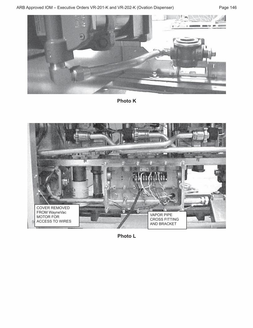
! c'9*&'"61'"&:+*%"6$5'3"-%*9"61'"F:%'"?662;>3":66:)1'4"6*"61'"GNOK")*$+72;>3"$;4'%"61'"
barrier and the inlet of each pump, see photos K & L.
! c'9*&'"61'"GNOK"AT0"?662;>"-%*9"5*61"GNOK")*$+72;>3!""VDH0_,AC"H3'":"+2+'"@%';)1"
*;"61'"GNOK")*$+72;>3"@1';"%'9*&2;>"61'"GNOK"AT0"?662;>3"6*"+%'&';6"7**3';2;>"*-"61'"
upper vapor piping.
! X**3';":;4"3724'"5:)/"61'";$63"*;"61'"&:+*%"6$5'3")*;;')6'4"6*"61'"*$67'6"324'"*-"5*61"
WayneVAC™ pumps and the vapor cross that’s mounted to the base of the dispenser.
A,0BC"01'"&:+*%"6$5'3"@277"36:("2;"61'"?662;>3"$;627"61'"`DV"+$9+3":%'"%'9*&'4!
! Remove the sheet metal screws on each side that secure the VAC pump mounting
5%:)/'6"6*"61'"-%:9'":;4"%'9*&'"+$9+N5%:)/'6":33'957("-%*9"423+';3'%":;4"&:+*%"
6$52;>!"",;"*;'"';48"26"@277"5'";')'33:%("6*"%'9*&'"61'"+%*4$)6"?76'%"2;"*%4'%"6*">'6"61'"
+$9+N5%:)/'6":33'957("*$6!""d'"3$%'"(*$"1:&'"+'6%*7'$9"e42:+'%3f":&:27:57'"6*":53*%5"
:;("3+277'4"-$'7!""A,0BC"c'2;36:77"+%*4$)6"?76'%":-6'%"`DV"+$9+"%'9*&:7!
! c'9*&'"61'"GNOK"F:%'"?662;>3"-%*9"':)1"324'"*-"61'"&:+*%")%*33!
!"# $$%&'()#*+,#-#./(0123'(#+%)(%4#5!67896:#;<)#5!67876:#=+';23&<#>34$(<4(%?## @;A(#9YT
Photo K
^+5.!#!.,+5.>#
O!+,#U;R<(5;0#
,+D+!#O+!#
^^.QQ#D+#U*!.Q
VAPOR PIPE
^!+QQ#O*DD*_`#
_>#"! ^:.D
Photo L

!"# $$%&'()#*+,#-#./(0123'(#+%)(%4#5!67896:#;<)#5!67876:#=+';23&<#>34$(<4(%?## @;A(#9YC
9. Balance Removal:
! c'9*&'"61'"&:+*%"6$5'3"-%*9"61'"F:%'"?662;>3":66:)1'4"6*"61'"GNOK")*$+72;>3"$;4'%"
the barrier and from the vapor cross.
! c'9*&'"61'""F:%'"?662;>"-%*9"5*61"GNOK")*$+72;>3"*-":5*&'!""VDH0_,AC"H3'":"+2+'"
@%';)1"*;"61'"GNOK")*$+72;>3"@1';"%'9*&2;>"61'""F:%'"?662;>3"6*"+%'&';6"7**3';2;>"
of the upper vapor piping.
! c'9*&'"61'"F:%'"?662;>3"-%*9"':)1"324'"*-"61'"&:+*%")%*33!
10. INSTALLING THE VP1000 SYSTEM:
A,0BC"61:6"61'"9*$;62;>"5%:)/'6"*;"61'"`TMQQQ"9$36"5'"%*6:6'4"YQg"6*"3')$%'"61'"+$9+"
on this shelf. When installed in the dispenser, the vacuum pump INLET must be on top
and the OUTLET on the bottom
PHOTO M

!"# $$%&'()#*+,#-#./(0123'(#+%)(%4#5!67896:#;<)#5!67876:#=+';23&<#>34$(<4(%?## @;A(#9YW
! T7:)'"61'"`TMQQQ"&:+*%"+$9+"*;"61'"31''6"9'6:7"5%:)/'6"@261"61'"+$9+"';4"6*@:%43"
61'"7'-68"$+6$%;'4"F:;>'8"3''"+1*6*"^!""#')$%'"@261"*;'"MNOPLQ"I"RNSK"F:6"1':4"):+"
screw, washer and nut in each of the motor mounting holes closest to the electrical
end.
NOTE: DO NOT USE PIPE SEALING COMPOUND ON ANY ELECTRICAL CONDUIT
FITTINGS.
Mount the electrical conduit on the VP1000: (See Photo N Below)
! Get the 1/2” x 3” conduit nipple and thread through the motor wires to secure the
nipple into the motor.
! Install the 1/2” electrical elbow to the nipple from above – use care not to twist the
wires during the installation. Completely tighten the elbow to face toward the rear of
the VP1000, see photo N.
! Next, install, in the elbow, the 1/2” close nipple, followed by the female half of the
electrical union.
! X:367(8"$3'"0'F*;"6:+'"6*"2;36:77":"MNLK"AT0"I"RNSK"F:%'"'75*@"2;"61'"e_Af"+*%6"*-"61'"
+$9+!""h:)'"61'"'75*@"6*"61'"%2>16"@1';"7**/2;>":6"61'"-%*;6"*-"61'"+$9+8"3''"+1*6*"
N.
PHOTO N PHOTO O

!"# $$%&'()#*+,#-#./(0123'(#+%)(%4#5!67896:#;<)#5!67876:#=+';23&<#>34$(<4(%?## @;A(#9Y]
Mount the VP1000 and the vapor plumbing:
!^*$;6"61'"+$9+N5%:)/'6":33'957("2;"61'"423+';3'%"-%*9"61'"JdK"324'8"\6123"23"61'"
side opposite the IGEM board #173976) using four 1/4” x 1/2 sheet metal screws, see
photo O, View From “B” Side.
! On the ‘B’ side of the dispenser, in the hydraulics area, locate the 3/4” vapor coupling
*;"61'"%2>16"1:;4"324'"$;4'%"61'"&:+*%"5:%%2'%!"_;36:77":"GNOK"AT0"I"RNSK"F:%'"'75*@"
into the 3/4” coupling, completely tighten to face directly toward the cover panel
opening.
! Still on the ‘B’ side, locate the left end 3/4” vapor coupling protruding from the vapor
5:%%2'%!""_;36:77":"GNOK"AT0"I"RNSK"F:%'"36%:2>16"?662;>"2;6*"61'"61%':4'4"1*7'!"
! b'6"61'"+%'-*%9'4"RNSK"6$5'"7:5'7'4"7'-6":;4":66:)1"61'"31*%6"7'>"6*"61'"7'-6"?662;>"i$36"
installed. Do not completely tighten at this time.
! b'6"61'"+%'-*%9'4"6$52;>"7:5'7'4"%2>16":;4"2;36:77"2;"61'"%2>16"';4"'75*@"?662;>!""E*"
not completely tighten at this time.
11. CONNECTING VAPOR LINES: (ref. Photos P, Q & R)
PHOTO P PHOTO Q
!^:/'"61'"+2+'"61%':4")*;;')62*;3"5'7*@"$32;>"+2+'"61%':4")*9+*$;4":3"%'<$2%'4!"
! b'6"61'"MNLK"AT0"I"RNSK"I"RNSK"F:%'"6''":;4"2;3'%6"5'6@'';"61'"6@*"+%'-*%9'4"RNSK"
copper tubes to be sure the tubes can be securely tightened, but DO NOT COMPLETELY
TIGHTEN.

!"# $$%&'()#*+,#-#./(0123'(#+%)(%4#5!67896:#;<)#5!67876:#=+';23&<#>34$(<4(%?## Page 150
! Remove the tee and thread into the 1/2” street elbow, tighten to position shown in photo
Q. To the elbow, add the 1/2” reducing tee and orient tee so the 1/4” branch opening is
75° to the elbow (facing the installer) with the elbow on the right and facing up. Install
the 1/4” plug into the 1/4” opening on the tee.
! Install the 1/2” close nipple into the tee and follow with the 1/2” ball valve. Orient the ball
valve so the lever is on the bottom when the 1/4” plug is facing sideways, see photo P.
! _;36:77"61'"MNLK"I"RNSK"36%:2>16"F:%'"?662;>"2;6*"61'"5:77"&:7&'!
! c'2;36:77"61'"RNSK"F:%'"6''"5:)/"5'6@'';"61'"6@*"+%'-*%9'4"+2+'38"@261"61'"F:%'"?662;>"
-:)2;>"61'"`TMQQQ":;4"?;:7"62>16';"61'"F:%'";$63!""01'"5:77"&:7&'"7'&'%"31*$74"5'"*;"61'"
bottom and the 1/4” pipe plug horizontal facing you. Be sure the slope of the two pipes
is downward and slopes to the tee.
! Measure and cut a length of 5/8” OD copper tube necessary to run from the pump inlet
F:%'"?662;>"6*"61'"F:%'"?662;>"*;"61'"5:77"&:7&'!""V$6"61'")*++'%"6$52;>":;4"3724'"*;"61'"
F:%'";$63"5'-*%'"F:%2;>"61'"';43!""V:%'-$77("+*3262*;"6123"&:+*%"6$5'"6*":72>;"?662;>3"-*%"
62>16';2;>!""#')$%'"6$52;>")*;;')62*;3"6*"61'"+$9+":;4"5:77"&:7&'!""H3'"):%'";*6"6*"/2;/"
the tubing and maintain the slope downwards.
! On the “A” side of the dispenser, install the 3/4” pipe plug to the left end of the vapor
)%*33":;4"61'"GNOK"AT0"I"RNSK"F:%'"'75*@"2;"61'"%2>16"';4!"V*9+7'6'7("62>16';"61'"F:%'"
elbow so it is horizontal to slightly upward facing the out port of the VP1000.
! ,;"61'"edf"324'8"2;36:77"61'"MNLK"AT0"I"RNSK"F:%'"'75*@"2;6*"61'"*$6"+*%6"*-"61'"`TMQQQ!"
V*9+7'6'7("62>16';"$;627"1*%2j*;6:7"6*"4*@;@:%4"-:)2;>"61'"F:%'"'75*@"*;"61'"&:+*%"6''!""
(Use tape, not pipe dope)
!^':3$%'":;4")$6":++%*+%2:6'"7';>61"*-"RNSK")*++'%"6$52;>"6*"%':)1"-%*9"61'"F:%'"?662;>"
*;"61'"&:+*%"")%*33"6*"61'"?662;>"2;"61'"`TMQQQ"*$6"+*%6!""H3'"RNSK"6$52;>"5';4'%"6*"?6"
+2+'":++%*+%2:6'7("6*"?662;>3"2-";')'33:%("3''"+1*6*"k!"
! #724'"*;"61'"F:%'";$63"5'-*%'"F:%2;>"61'"';43!
! V:%'-$77("+*3262*;"6123"&:+*%"6$5'"6*":72>;"?662;>3"-*%"62>16';2;>!""#')$%'"6$52;>"
)*;;')62*;3"6*"61'"+$9+":;4"&:+*%"")%*33!""H3'"):%'";*6"6*"/2;/"61'"6$52;>":;4"
maintain the slope downwards.
12. INSTALLING THE SEALED NIPPLE ASSEMBLY: (See Photos R & S)
NOTICE: THE INTERFACE MODULE THAT IS SUPPLIED HAS A HARNESS
ATTACHED AND A WIRING PLUG FOR THE AC CONNECTIONS. ALSO SUPPLIED IS
THE SEALED NIPPLE ASSEMBLY (1346) THAT MUST BE INSTALLED BETWEEN THE
ELECTRONICS AND HYDRAULIC AREAS OF THE DISPENSER CABINET.
! X**/2;>"2;"61'"JdK"324'"*-"61'"'7')6%*;2)3"):52;'68";*62)'"*;"61'"7*@'%"7'-6"*-"61'"
electronics board support column, there is either a plugged hole (remove plug at this
time),or an open hole where the WayneVac conduit was removed from the hydraulics
to the electronic compartment. Get the 1346 Sealed Nipple assembly and remove the
?%36";$6":;4"@:31'%!"0$%;"61'"%'9:2;2;>";$6"4*@;"*;"61'";2++7'":3"-:%":3"26"@277">*!

!"# $$%&'()#*+,#-#./(0123'(#+%)(%4#5!67896:#;<)#5!67876:#=+';23&<#>34$(<4(%?## Page 151
! Carefully slide the threaded nipple end wires down from the electronics cabinet to the
hydraulics area see photo S.
! #724'"61'"@:31'%":;4";$6"%'9*&'4":5*&'8"5:)/"*&'%"61'"@2%'3":;4"61%':4"*;"6*"61'"
nipple, approximately 4 turns, do not tighten until electrical is complete see photo S.
! Install a 3/4” electrical elbow onto the sealed nipple. Tighten to face the female half of
the electrical union that’s attached to the VP1000.
! Install a 3/4” x 1/2” electrical reducing bushing to the 3/4” elbow followed by a 1/2” x 7”
electrical nipple, then a 1/2” electrical coupling followed by a 1/2” x 5” electrical nipple.
! Get the “J” box and install a 3/4” x 1/2” reducing bushing in each 3/4” threaded hub.
! Position the “J” box as shown in photo R, pull wires through and install onto the 1/2” x
5” electrical nipple being careful not to twist the wires.
! Install a 1/2” electrical close nipple to the bottom port of the “J” box.
! Get the 1/2” pull elbow and remove the cover. Install onto the 1/2” close nipple and
tighten to the position shown in photo R.
! Attach the male half of the electrical union to the pull elbow. Pull wires from the female
half of the union through the male half, through the pull elbow and into the “J” box.
! Tighten the union half’s together being careful not to pinch wires and install cap on
elbow.
! Tighten the nuts on the sealed nipple to secure to barrier panel.
PHOTO R PHOTO S
! Leaving about 6” of wire on both the wires coming from the motor and from the sealed
nipple, cut off excess wire and strip approximately 1/2” of insulation from all wires.
! Use wire nuts to join the wires, color for color, together. There may be some extra wires
in some sealed nipples, cap these off and dress aside.
! k''+"@2%'3")7':%"*-"+2;)1"+*2;63":;4"-%*9"2;6'%-'%';)'8"9:/'"3$%'";*"@2%'3"*&'%1:;>"
the box openings and replace the cover on the junction box.

!"# $$%&'()#*+,#-#./(0123'(#+%)(%4#5!67896:#;<)#5!67876:#=+';23&<#>34$(<4(%?## Page 152
13. WIRING INSIDE THE ELECTRONICS COMPARTMENT
! Cut the wires coming from the sealed nipple assembly in the electronics cabinet at least
twenty inches long and strip all wires 1/2”.
! Connect the wires from the sealed nipple to the interface module as follows:
"!d7:)/"@2%'"6*"e9*6*%"e"*;"9*4$7'
"!White wire to ‘neutral’ on module
"!Red wire (either) to ‘output 1’ on module
"!Red wire (other) to ‘output 2’ on module
"!Orange wire to ‘fault common’ on module
"!Purple wire to ‘fault input’ on module
"!Green wire needs a #8 ring tong lug installed and connected to any chassis
ground (frame)
"!Some sealed nipples may have some extra wires, cap these and bundle them
neatly out of the way.
! 01'"57:)/":;4"@126'"6@236'4"+:2%"*-"@2%'3"@261":")*;;')6*%"31*$74"5'")*;;')6'4"6*":;"
available AC outlet on the dispenser Relay Board #887225 see photo T.
! The male/female multiconductor cable that is wired to the interface module is routed
up to the computer board, J3. Disconnect the valves cable already in J3 and install in
the female side of the double connector on the harness. The entire assembly is then
2;36:77'4"5:)/"2;6*"lG"*;"61'"V*9+$6'%"5*:%4"mM GY Z"3''"+1*6*"0!
! Carefully position the wired module on the edge of the center upright sheet metal panel
JdK"324'8"3'7')6":"57:;/"1*7'8":;4"3724'"*&'%"61'"SPGL"02;;'%9:;";$6"3$++72'4"2;"61'"
'7')6%*;2)3"/26!""^*$;6"61'"9*4$7'"6*"61'"02;;'%9:;")72+"$32;>"61'"SPGL"I"RNSK"3)%'@":;4"
washer supplied.

!"# $$%&'()#*+,#-#./(0123'(#+%)(%4#5!67896:#;<)#5!67876:#=+';23&<#>34$(<4(%?## @;A(#9VB
*`.,#^+,@XD.!######
BOARD.
,+>X\.#^ "\.
5 \5.Q#^ "\.
!.\ a#"+ !>
.,@Da#
\+^ D*+_Q
PHOTO T
! Install the following labels supplied:
!" NOTICE label for current increase (1405), install on the frame rail near the
existing power consumption label.
!" Large NOTICE label (1406) relating to the vapor recovery upgrade and how to
reset the electronic module should be installed near the module, where it will
be readily visible to a service technician on the junction box cover.
!" HX8"%'6%*?6"/26"24';62?):62*;";$95'%"\MOMQ]8"2;36:77"*;"61'"'7')6%*;2)"9*4$7'!
!"# $$%&'()#*+,#-#./(0123'(#+%)(%4#5!67896:#;<)#5!67876:#=+';23&<#>34$(<4(%?## @;A(#9VY
14. Connecting Healy Systems Dispensing Equipment
! Completing the connection of Healy Systems dispensing equipment requires the
installation of Healy Systems Phase II dispenser adaptors, hoses and nozzles
(Hanging Hardware).
! If applicable, remove existing non-Healy hanging hardware (from the dispenser
product outlet adaptor to and including the nozzles).
! "`:+*%"%':4("423+';3'%3"9:("%'<$2%'":"=':7("#(36'93":4:+6*%"6*"9:/'"61'"1*3'"
threads compatible with other Healy Systems equipment. Install necessary adaptor
-*77*@2;>"2;36%$)62*;3"+:)/'4"@261"61'":4:+6*%!""`:%2*$3":4:+6*%3":;4"+2>6:273"
:%'":&:27:57'8"4'+';42;>"*;"1*@"61'"423+';3'%"23")*;?>$%'4C""^GO"9'6%2)"\=':7("
designation F3 or S3) or balance ready (Healy designation S4).
! Healy Vapor Recovery Hoses are available in various lengths to satisfy local
ordinances and still provide “far side” fueling capability. Install these following
instructions contained on the shipping box.
! d%':/:@:(3":%'"%'<$2%'4C""_;36:77"'261'%"^*4'7"S QM``"5%':/:@:("*%"^*4'7"SQ ""
3@2&'7"5%':/:@:(n"2;36:77"$32;>"61'"2;36%$)62*;3"3$++72'4"@261"61'"$;26!
! The Healy Systems nozzle Model 900 (EVR) is the only nozzle necessary to complete
61'"$+>%:4'!""V1')/"6*"5'"3$%'"61'";*jj7'"1:;>'%"23"9*$;6'4"2;"61'"12>1'36"+*3262*;!""
d'"3$%'"6*")1')/"-*%"+%*+'%"?6"2;"61'";*jj7'"1*736'%":;4"61:6"61'";*jj7'"):;"5'"7*)/'4"
2;"61'"*--"+*3262*;!""D73*8"5'"3$%'"61:6"@1';"61'";*jj7'"23"7*)/'48"61:6"61'"423+';3'%"
):;";*6"5'":)62&:6'4"-%*9"61'"7*)/'4"+*3262*;!

!"# $$%&'()#*+,#-#./(0123'(#+%)(%4#5!67896:#;<)#5!67876:#=+';23&<#>34$(<4(%?## Page 155
15. VP1000 Theory of Operation
The Healy Systems VP1000 is a self-contained rotary vane pump, designed for gasoline vapor
recovery utilizing various parts of the Healy System Vapor Recovery product line. It is intended
-*%"$3'"5("'261'%",B^"423+';3'%N+$9+"9:;$-:)6$%'%3"*%":3":;":-6'%"9:%/'6":44P*;" 6*"9:/'"
existing equipment compatible with Healy System technology. In order to convert to ‘others’
equipment, an electronic interface is required to adapt the targeted pump/dispenser to the new
vapor recovery equipment. The interface senses when authorization to dispense has been
given and sends signals to the motor to operate at a low speed for one hose, or a higher speed
for two hoses. It also functions to shut off the pump/dispenser if it senses that the vapor pump
23";*6"*+'%:62;>"+%*+'%7(!""01'"&:)$$9"23"%'>$7:6'4":6":"7'&'7"3$-?)2';6"6*")7':%"72<$24">:3*72;'"
from the vapor path in MPD applications. The actual amount of vapors withdrawn is controlled
5("61'"=':7(";*jj7'8"263'7-8"2;"%'3+*;3'"6*"61'"72<$24">:3*72;'"F*@"%:6'!"
MOTOR SPECIFICATIONS
[&%4($&I(%# # # # # # # # 9LW
# 5&F2;A(# # # # # # # # 9785 ^
INTERFACE SPECIFICATIONS
*<$12#'&F2;A(# # # # # # # 978#5 ^
!(F;R#01%%(<2#0;$;032R### # # #### # ###V # ^
*<$12#43A<;F4# # # # # # # 978#5 ^
# ,&2&%#*<$12#43A<;F# ########V#5>^#b#78#[c#V8d#>12R#^R0F(

!"# $$%&'()#*+,#-#./(0123'(#+%)(%4#5!67896:#;<)#5!67876:#=+';23&<#>34$(<4(%?## @;A(#9VT
16. TESTING THE SYSTEM:
P" V:%'-$77("%'&2'@":77"@*%/")*9+7'6'48"5'2;>"3$%'":77"9')1:;2):7"i*2;63":%'"61*%*$>17("
tightened and electrical connections sealed.
- Open the product crash valves and restore power to the dispenser.
- With the power on, but no nozzles authorized, the VP1000 should not be running
(unless the ambient temperature is below 40°F), but the power LED (yellow) should
be energized on the interface module.
- Authorize one handle and the vacuum system should activate when the gasoline
F*@")*;6%*7"&:7&'"23"';>:>'4!""c'+':6"-*%":77"*61'%";*jj7'38"2;42&24$:77("6'362;>"':)1"
nozzle on each side of dispenser. With each authorization, one of the green LED’s
on the interface module should illuminate and the VP1000 activate.
- Note: For unihose dispensers, conduct individual tests for each product grade on
each side of the dispener to ensure that the same LED activates for all grades on the
same side. If the other LED activates, wiring needs to be corrected.
- Authorize one nozzle and listen to the speed of the VP1000. With only one nozzle
activated, the speed will be slower than if a nozzle on each side is activated. Activate
a nozzle on the other side of the dispenser and listen for the speed to change.
- To test the tightness of the vapor plumbing installed on the suction side of the
system requires a 0-100” water column gauge. Connect the gauge into the 1/4” test
port of the reducing tee installed earlier in section 11 Photo P. Continue by following
and completing the START-UP / NEW INSTALLATION / WARRANTY / ANNUAL
TESTING FORM.

!"# $$%&'()#*+,#-#./(0123'(#+%)(%4#5!67896:#;<)#5!67876:#=+';23&<#>34$(<4(%?## Page 157
17. TROUBLESHOOTING VP1000
! Use extreme care and caution when performing the tests listed below. If 120 VAC is
accidentally applied to the fault or DC terminals, the module will be destroyed.
! With power applied to the dispenser, but no products authorized, there should be
120 VAC between neutral and power in on the module terminal strip.
! As above, with any product authorized, there should be single speed power applied
6*"61'"`TMQQQ!""`'%2-("6123"5(")1')/2;>"-*%"LPG"`EV"-%*9",H0TH0"M"\cBE"._cB]"6*"
hDHX0"V,^^,A"\,cDAbB"._cB]8"\*%"-%*9",H0TH0"L"0,"hDHX0"V,^^,A]":73*n"
one GREEN LED should be illuminated. With a second product authorized on the
opposite side of the dispenser i.e. one product on each side, the motor should
operate at higher speed and there should be 2-3 VDC on both output 1 and 2 (to fault
common) and both GREEN LED’s should be illuminated.
! With the pump running, a fault can be simulated by shorting, with a jumper wire, the
“FAULT INPUT” (purple wire) to FAULT COMMON (orange). This should cause the
motor to shut off, the solenoid valves to lose power and the dispenser to shut down.
Also, as long as the short is maintained, the red LED will be illuminated. Removing
the short will not automatically reset the module. To reset the module, remove
the short, remove power to the dispenser for twenty seconds and restore power.
The module should now be reset and the red led extinguished. This can also be
accomplished by using the power reset (PWR RESET) on the module.
! If diagnosing a problem where the LED is already illuminated, a steady light indicates
a low current condition, therefore expect a vane or rotor problem. If the LED is
572;/2;>8"61:6"2;42):6'3":"12>1")$%%';6")*;4262*;":;4"@*$74"'I+')6"6*"?;4":"i:99'4"
%*6*%"*%"&:+*%"72;'"F**4'4"@261"+%*4$)6!""#''"#6:%6P$+"N"A'@"_;36:77:62*;"N".:%%:;6("N"
Annual Testing Form.
! 01'"'7')6%*;2)3"*-"61'"9*6*%"@277"9:/'"61%''":66'9+63"6*"1:&'":"3$))'33-$7"36:%6"*-"
the motor. If it detects a problem, on the fourth unsuccessful start, it will short the
fault line to signal minus (DC-) and shut down the electronics.
MC100 Interface Module

!"# $$%&'()#*+,#-#./(0123'(#+%)(%4#5!67896:#;<)#5!67876:#=+';23&<#>34$(<4(%?## Page 158
18. VP1000 Vane & Rotor Service & Replacement Guide
Caution Disconnect power before beginning service.
9N# DE(#I&%P#;%(;#must G(#0F(;<#;<)#E;'(#41HK03(<2#F3AE23<AN
2. Disconnect the vapor piping connected to the IN and OUT ports of the VP1000 cover assembly.
BN# !(M&'(#2E(#H&1%# FF(<#E(;)#40%(I4#;<)#F&0P#I;4E(%4#2E;2#4(01%(#2E(#$1M$#0&'(%#;44(MGFR#2E(#$1M$#E&143<A#;<)#
remove the cover carefully.
Caution Use a spill cloth when removing the cover, as there may be some gasoline inside the pump cavity.
YN# ^;%(H1FFR#21%<#2E(#%&2&%#;44(MGFR#GR#E;<)#1<23F#2E(#4E;H2#P(R#<&20E#
34#;2#2E(#97#&e0F&0P#$&4323&<N#=Q((#O3A1%(#9?
5. Remove the rotor, vanes and shaft key from the pump housing.
Note: @F;0(#R&1%#E;<)#&%#;#0&<2;3<(%#1<)(%#2E(#%&2&%#IE3F(#%(M&'3<AN#
>&#<&2#14(#;<R#4E;%$#&Gf(024#2E;2#I&1F)#40%;20E#2E(#41%H;0(4#&H#
the pump cavity, pump shaft, rotor, or vanes.
TN# !&2;2(#2E(#4E;H2#GR#E;<)N#*H#2E(#4E;H2#)&(4#<&2#%&2;2(#H%((FRJ#2E(#
(<23%(#';011M#$1M$#<(()4#%($F;0(M(<2#=$L<#5@98886V?N
CN# *H#2E(#%&2&%#;<)#';<(4#;%(#0%;0P()J#0E3$$()J#(/0(443'(FR#I&%<#&%#
excessively dirty, the rotor and vanes should be replaced because
0F(;<3<A#I3FF#<&2#%(M()R#2E(4(#0&<)323&<4#=$L<#5@98885!^#&%#
5@98885!^6@?N
WN# *H#2E(%(#34#<&#'343GF(#);M;A(J#14(#;#F3<26H%((#0F&2E#I32E#34&$%&$RF#
alcohol to clean the rotor and vanes.
]N# X43<A#;#F3<26H%((#0F&2E#I32E#34&$%&$RF#;F0&E&FJ#2E&%&1AEFR#0F(;<S#2E(#
inside of the pump ring and rear of the pump cavity, the rotor shaft,
and the inside of the pump cover.
10. Reposition the shaft (if necessary) so that the shaft key notch is
3<#2E(#97#&e0F&0P#$&4323&<N#*<42;FF#2E(#0F(;<()#&%3A3<;F#&%#<(I#4E;H2#
key onto the shaft.
99N# ^;%(H1FFR#3<42;FF#2E(#0F(;<()#&%3A3<;F#&%#<(I#%&2&%#&<2E(#4E;H2#
H&FF&I()#GR#2E(#0F(;<()#&%3A3<;F#&%#<(I#';<(4#3<2E(#%&2&%N
Note: DE(#%&2&%#;44(MGFR#4E&1F)#4F3)(#&<#2E(#4E;H2#(;43FRJ#I32E&12#
excessive force. (Rotors and vanes are reversible)
Figure 1VP1000VRC
Carbon Rotor
(limited availability)
Shaft Key
_&20E
Vane
Shaft Key
_&20E
Vane
Figure 2: VP1000VRC-P
Enhanced
Carbon Rotor
97N# \3AE2FR#F1G%30;2(#;<)#3<42;FF#2E(#<(I#+6!3<A#H&%#2E(#$1M$#E&143<AN
Note: >&#<&2#;FF&I#;<R#F1G%30;<2#2&#A(2#3<43)(#2E(#$1M$#E&143<AN
9BN# *<42;FF#2E(#$1M$#0&'(%#143<A#2E(#H&1%# FF(<#E(;)#40%(I4#;<)#F&0P#I;4E(%4#%(M&'()#3<#42($#B#;<)#0%&44#23AE2(<N
Note: X4(#0;123&<#IE(<#4F3)3<A#2E(#$1M$#0&'(%#&'(%#2E(#+6!3<A#4(;F#2&#$%('(<2#01223<A#&%#2(;%3<AN
9YN# !(60&<<(02#2E(#';$&%#$3$3<A#2E(#IN and OUT#$&%24#&H#2E(#$1M$#0&'(%#;44(MGFR#2E;2#I;4#%(M&'()#3<#Q2($#7N
9VN# !(6;$$FR#$&I(%N#D(42#H&%#<&%M;F#&$(%;23&<N#=Q((#5@9888#5;011M#@(%H&%M;<0(#D(42#@%&0()1%(?

!"# $$%&'()#*+,#-#./(0123'(#+%)(%4#5!67896:#;<)#5!67876:#=+';23&<#>34$(<4(%?## Page 159
QD !D6X@L_.U#*_QD \\ D*+_L#U !! _DaL# __X \#D.QD*_`#O+!,#=!('N#98L8C?
[. \a#5@9888#5 ^XX,#@X,@##
Date___________________
BOTH SIDES OF THIS TEST FORM MUST BE COMPLETED FOR NEW INSTALLATIONS
o" #6:%6P$+"N"A'@"2;36:77:62*;3"W")*9+7'6'"#_EB"D":;4"3')62*;3"G8"O8"R":;4"Z"*-"#_EB"d!""#$5926""-*%93"6*"=':7("
Systems.
o" .:%%:;6("#'%&2)'"*%"D;;$:7"0'362;>"W")*9+7'6'")*;6:)6"2;-*%9:62*;8"423+';3'%"9:/'8"&:)$$9"+$9+"3'%2:7"m"
:;4"61'"6'363"2;"3')62*;3"M":;4"L"*;"#_EB"D":;4")*;4$)6"61'":++%*+%2:6'"6'363"3+')2?'4"*;"#_EB"d!""#$5926"
Forms to Healy Systems.
Q.!5*^.#^+,@ _a#_ ,. D.\.@[+_.
Q.!5*^.#D.^[_*^* _ [. \a#D.^[#^.!D#g
QD D*+_# >>!.QQ ^*Da STATE
DISPENSER MAKE VACUUM PUMP SERIAL #
SIDE ADISPENSER EQUIPMENT CHECKLIST - Parts A-1 and A-2 YES NO*
A-1 *4#;FF#2E(#3<42;FF()#)34$(<4(%#E;<A3<A#E;%)I;%(#F342()#3<#./E3G32#9#&H#./(0123'(#+%)(%#
VR-201 or VR-202?
A-2 Proper installation of the VP1000 requires the test port and ball valve on the inlet side
of the vacuum pump. Are the test port and ball valve installed correctly?
*If the answer to either A-1 or A-2 is NO, the Healy Warranty is Void.
A-3h# D[.#O+\\+U*_`#D.QD#U*\\#@.!O+!,# #@+Q*D*5.#@!.QQX!.#\. :#^[.^:#+O#D[.#5 ^XX,#@X,@J#
>*Q@._Q.!#5 @+!#@*@*_`J#[ _`*_`#[ !>U !.# _># \\#_+ii\.Q#+_#"+D[#Q*>.Q#+O#D[.#
>*Q@._Q.!N#########
h# D[.#5@9888#+XD\.D#*Q#_+D#^+__.^D.>#D+#X_>.!`!+X_>#@*@*_`#>X!*_`#D[*Q#D.QDN
CAUTION: REGULATE GASEOUS NITROGEN TO 2.5 PSI (~70” WC) MAXIMUM BEFORE TESTING
9N###*<42;FF#;#86988#3<0E#I;2(%#0&F1M<#=j#I0?#M(0E;<30;F#A;1A(#;2#2E(#5@9888#2(42#$&%2N#
7N###X4(#2E(#I;2(%#0&F1M<#A;A(#$&4323'(#=E3AE?#$%(441%(#$&%2N
BN###`;4(&14#<32%&A(<#A;4#0;<#<&I#G(#0&<<(02()#2E(#&12F(2#=(/E;142?#$&%2#&H#2E(#5@9888N
YN###D(42#$%(441%(#cannot#(/0(()#C8j#I0N
5. Slowly#3<2%&)10(#2E(#A;4(&14#<32%&A(<#2&#;#$%(441%(#G(2I((<#T8#-#C8k#I0N#
TN### H2(%#%(;0E3<A#2E(#$%(441%(#%;<A(J#0F&4(#2E(#';F'(#41$$FR3<A#2E(#A;4(&14#<32%&A(<N
CN###!(0&%)#2E(#3<323;F#$%(441%(#%(;)3<A#&<#2E(#A;1A(#6#&G4(%'(#;<)#%(0&%)#2E(#K<;F#$%(441%(#%(;)3<A#;H2(%#T8#4(0&<)4N
WN# \(;P4#M142#G(#%($;3%()#IE(<#2E(#$%(441%(#H;FF4#M&%(#2E;<#Yk#I0#3<#T8#4(0&<)4N
9. Retest until all leaks have been repaired.
98N#!(0&%)#2(42#%(41F24#3<#Q(023&<# 6YN
A-4 Initial Pressure test reading (“wc) Pressure test reading after 60 seconds
(“wc)PRESSURE TEST
2.5 PSI (~70”wc) Maximum

!"# $$%&'()#*+,#-#./(0123'(#+%)(%4#5!67896:#;<)#5!67876:#=+';23&<#>34$(<4(%?## @;A(#9T8
QD !D6X@L_.U#*_QD \\ D*+_L#U !! _DaL# __X \#D.QD*_`#O+!,#=!('N#98L8C?
[. \a#5@9888#5 ^XX,#@X,@##
Date___________________
BOTH SIDES OF THIS TEST FORM MUST BE COMPLETED FOR NEW INSTALLATIONS
o" #6:%6P$+"N"A'@"2;36:77:62*;3"W")*9+7'6'"#_EB"D":;4"3')62*;3"G8"O8"R":;4"Z"*-"#_EB"d!""#$5926""-*%93"6*"=':7(
Systems.
o" .:%%:;6("#'%&2)'"*%"D;;$:7"0'362;>"W")*9+7'6'")*;6:)6"2;-*%9:62*;8"423+';3'%"9:/'8"&:)$$9"+$9+"3'%2:7"" "
" m":;4"61'"6'363"2;"3')62*;3"M":;4"L"*;"#_EB"D":;4")*;4$)6"61'":++%*+%2:6'"6'363"3+')2?'4"*;"#_EB"d!""#$5926"" "
Forms to Healy Systems.
SIDE BWarranty Service
^&M$F(2(#D%&1GF(4E&&23<A#Q(023&<4
B-1 and B-2
Start-up/ New Installations/ Annual Testing
^&M$F(2(#Q(023&<4
B-3 through B-6
B-1 Control Module Fault Light
(Circle one) Flashing (LED) Steady (LED)
1. All fault conditions require removal and cleaning or replacement of the rotor and vanes located inside the
vacuum pumps round front cover assembly. Use the VP1000 ROTOR & VANE SERVICE AND REPLACE-
MENT GUIDE 3<#2E(#;$$F30;GF(#)34$(<4(%#%(2%&K2#M;<1;F#&H#2E(# !"# $$%&'()#*<42;FF;23&<J#+$(%;23&<#;<)#
,;3<2(<;<0(#,;<1;F#H&%#./(0123'(#+%)(%4#5!67896:#;<)#5!67876:N#
7N# ^F(;<#;FF#41%H;0(4#3<0F1)3<A#';<(4J#%&2&%J#%&2&%#E&143<A#;<)#0&'(%#;44(MGFRN#
BN# ,;<1;FFR#4$3<#;<)#3<4$(02#2E(#M&2&%#4E;H2#H&%#G(;%3<A#I(;%#G(H&%(#%(63<42;FF3<A#2E(#%&2&%#P32N
YN# !($F;0(#M&2&%#IE(<#G(;%3<A4#&%#4E;H2#;%(#);M;A()#&%#I&%<N
VN###^E(0P#+6%3<A#4(;F#G(H&%(#%($F;03<A#%&2&%#0&'(%#;44(MGFRN
B-2 !(6 44(MGF(#L#!(4(2#5;011M#@1M$#;<)#,&)1F(N#=@&I(%#M142#G(#%(M&'()#H%&M#G&2E#2E(#';011M#$1M$#;<)#
the module for 20 seconds to reset the system?#143<A#2E(#$&I(%#%(4(2#4I320E#&<#2E(#,^988#M&)1F(N
B-3 9N# *<42;FF#86988#3<0E#I;2(%#0&F1M<#=j#I0?#';011M#M(0E;<30;F#A;1A(#;2#2E(#5@9888#2(42#$&%2N
7N# 12E&%3c(#2E(#)34$(<4(%#H&%#H1(F3<AN##DE(#5@9888#I3FF#G(A3<#2&#%1<N
BN# ^F&4(#2E(#G;FF#';F'(#;2#2E(#$1M$#3<F(2N##
YN# !(0&%)#2E(#3<323;F#';011M#%(;)3<A#&<#2E(#A;1A(#-#&G4(%'(#;<)#%(0&%)#2E(#K<;F#';011M#%(;)3<A#;H2(%#T8######
seconds.
5. Open the ball valve at the pump inlet.
TN# \(;P4#M142#G(#%($;3%()#IE(<#2E(#';011M#%(;)3<A#H;FF4#M&%(#2E;<#Yk#I0#3<#T8#4(0&<)4N
7. Retest until all leaks have been repaired.
WN# !(0&%)#);2;#3<#Q(023&<#"6YN
Note: If the initial vacuum reading is less than 60” wc, it could indicate a problem with the VP1000.
Remove the dispenser from service. Use the troubleshooting section of the manual to investigate
+%*57'9"*%")*;6:)6"61'"hh#"0')1;2):7"='7+"E'3/":6"SQQPYSOPZLZZ"-*%":33236:;)'!
>34$(<4(%#5;$&%#\3<(
Inte
grity
Test
B-4 5 ^XX,#D.QD#X43<A#
VP1000 as vacuum source
*<323;F#5;011M##2(42#%(;)3<A#=j#I0? 5;011M#2(42#%(;)3<A#;H2(%#T8#4(0N#=j#I0?
B-5 U32E#&<(#43)(#&H#2E(#)34$(<4(%#;12E&%3c()#=5@9888#%1<<3<A?#;<)#2E(#G;FF#';F'(#;2#2E(#$1M$#3<F(2#&$(<J#)34$(<4(#
3<#E;<)E(F)#$&4323&<#;#M3<3M1M#&H#8NV#A;FF&<4#&H#H1(F#3<2&#;#'(E30F(#&%#2(42#2;<PN##!(0&%)#2E(#';011M#F('(F#IE3F(#
dispensing. Repeat test for the other side of the dispenser.
9N###Q3)(#j k###>34$(<43<A#5;011M##llllllllllllk#I0
7N###Q3)(#j"k###>34$(<43<A#5;011M##llllllllllllk#I0
Note: If the dispensing vacuum is less than 60” wc, remove the dispenser from service. See the trouble-
31**62;>"3')62*;"*-"61'"9:;$:7"*%")*;6:)6"hh#"0')1;2):7"='7+"E'3/":6"SQQPYSOPZLZZ"-*%":33236:;)'!
Dis
penser
Vaacuum
Test
B-6 D(42#2E(#5@9888#5;011M#@1M$#H&%#<&%M;F#&$(%;23&<N##X4(#2E(#T#42($#$%&0()1%(#232F()J#jD(423<A#2E(#5@9888#
5;011M#@1M$#H&%#<&%M;F#&$(%;23&<#143<A#2E(#H&FF&I3<A#2(42#$%&0()1%(Sk#3<#Q(023&<#9N9#=U((PFR#*<4$(023&<#;<)#
D(423<A?#&H#2E(#[(;FR#QR42(M4#Q0E()1F()#,;3<2(<;<0(#)&01M(<2#3<#2E(# !"# $$%&'()#*<42;FF;23&<J#+$(%;23&<#
;<)#,;3<2(<;<0(#,;<1;F#H&%#2E(#[(;FR#@E;4(#**#.5!#QR42(M#<&2#*<0F1)3<A#*Q>N##DE34#34#2&#'(%3HR#2E;2#2E(#$1M$#
%(0&A<3c(4#IE(<#G&2E#43)(4#&H#2E(#)34$(<4(%#;%(#;023';2()#H&%#H1(F3<AN
>&(4#2E(#5@9888#5;011M#@1M$#0E;<A(#4$(()4#=;1)3GF(#3<0%(;4(?#IE(<#G&2E#43)(4#;%(#;023';2()#H&%#H1(F3<Am#####
############################################################################a(4####_&
*H#2E(#;<4I(%#34#<&J#use the troubleshooting section of the manual to investigate problem or contact the
hh#"0')1;2):7"='7+"E'3/":6"SQQPYSOPZLZZ"-*%":33236:;)'!"
Audib
le Incre
ase
Test
!($;3%4#6#^&MM(<24 D&#+G2;3<#!(21%<()#,;2(%3;F4# 12E&%3c;23&<#<1MG(%#=!, g?##^;FF#W886]WY6T7TT
O&%M4#0;<#G(#H;/()#2&#O%;<PF3<#O1(F3<A#QR42(M4#^142&M(%#Q(%'30(#;2#W88677V6]CWC