water droplet dynamic behavior during removal from a ... · water droplet dynamic behavior during...
TRANSCRIPT
598
Korean J. Chem. Eng., 31(4), 598-610 (2014)DOI: 10.1007/s11814-013-0282-6
INVITED REVIEW PAPER
pISSN: 0256-1115eISSN: 1975-7220
INVITED REVIEW PAPER
†To whom correspondence should be addressed.
E-mail: [email protected]
Copyright by The Korean Institute of Chemical Engineers.
Water droplet dynamic behavior during removal from a proton exchange membrane fuel
cell gas diffusion layer by Lattice-Boltzmann method
Golamreza Molaeimanesh and Mohammad Hadi Akbari†
Center for Fuel Cell Research, School of Mechanical Engineering, Shiraz University, Shiraz 71348-51154, Iran(Received 5 October 2013 • accepted 16 December 2013)
Abstract−A major challenge in the application of proton exchange membrane fuel cells (PEMFCs) is water manage-
ment, with the flooding of electrodes as the main issue. The Lattice-Boltzmann method (LBM) is a relatively new tech-
nique that is superior in modeling the dynamic interface of multiphase fluid flow in complex microstructures such as
non-homogeneous and anisotropic porous media of PEMFC electrodes. In this study, the dynamic behavior of a water
droplet during removal from gas diffusion layer (GDL) of a PEMFC electrode with interdigitated flow field is simulated
using LBM. The effects of GDL wettability and its spanwise and transverse gradients on the removal process are investigated.
The results demonstrate great influence of wettability and its spanwise and transverse gradients on the dynamic behavior
of droplets during the removal process. Although increasing the hydrophobicity of GDL results in better droplet re-
moval, its increase beyond a critical value does not show a significant effect.
Keywords: Multiphase Flow, Water Droplet, Proton Exchange Membrane Fuel Cell, Lattice-Boltzmann Method, GDL Micro-
structure
INTRODUCTION
Fuel cells are efficient energy conversion devices which directly
convert the chemical energy stored in a fuel into electrical energy
through electrochemical reactions. Among different types of fuel
cells, PEMFC has increasingly become the most promising candi-
date for the power source of future automotive and portable appli-
cations due to its low operating temperature, very low emissions
and high power density [1]. However, further improvements in per-
formance, durability and cost are necessary before their widespread
commercial application becomes a reality. Due to the low-temper-
ature operation of PEMFCs, the water generated by electrochemi-
cal reactions often condenses into liquid phase, flooding the catalyst
layer (CL), gas diffusion layer (GDL), and gas channels (GCs) [2,
3]. Avoiding electrode flooding is of critical importance for opti-
mal fuel-cell performance and durability [4], which makes accurate
modelling of water transport in PEMFCs essential. Many numerical
models from 1D to 3D, single-phase to multi-phase, microscopic
scale to macroscopic scale, also isothermal or non-isothermal, have
been proposed in the literature [5]. However, due to anisotropic and
non-homogenous transport properties of GDLs, only pore-scale sim-
ulation techniques such as LBM and pore network method which
can take into account these characteristics are able to provide an
accurate prediction.
Lattice-Boltzmann method (LBM) is a relatively new technique
suitable for simulating complex fluid systems, and hence has re-
cently attracted the interest of researchers in computational mechan-
ics. Due to its particulate nature and local dynamics, LBM has several
advantages over other conventional CFD methods, especially in
modelling multi-phase fluid flow in porous media, in dealing with
complex boundaries, in considering non-homogeneous and aniso-
tropic transport properties and in parallelization of the algorithm
[6]. Several investigations of water transport in fuel cell electrodes
have been conducted using LBM. In some of these, the liquid phase
is simulated as a continuous phase to predict parameters such as
permeability or capillary pressure [7-14]. In several other investiga-
tions, liquid phase is simulated as discrete droplets [15-21]. Since
continuous liquid water flow in micro-pores is never observed in
situ in a PEM fuel cell and, on the contrary, a series of discrete small
droplets in the GDL are often observed using the environmental
scanning electron microscope (ESEM) [22,23], the second group
of LB simulations seem more realistic.
In the present study, the dynamic behavior of a liquid water droplet
initially placed either on the GDL/micro-porous layer (MPL) inter-
face or on the GDL/land interface of a PEMFC electrode with inter-
digitated flow field is investigated through LB simulations. Because
the development of liquid water droplets in the GDL is started from
either GDL/MPL interface, especially at high current densities or
from GDL/land interface due to coolant flow through bipolar plates
[24], such initial droplet positions are considered. Since one of the
major parameters influencing water transport phenomenon, and there-
fore controlling the onset of flooding, is the wettability properties of
GDL, several simulations are conducted under different GDL wet-
tability conditions to investigate the effect of uniform and non-uni-
form wettability on the removal of droplets. The treatment of GDL
with a highly hydrophobic material such as polytetrafluoroethylene
(PTFE) is a conventional technique for mitigating GDL flooding,
which normally results in non-uniform PTFE distribution [25]. In
such a case, the GDL must be considered as a porous medium with
non-homogeneous and anisotropic wettability. However, in just a
few of the previous LB investigations the wettability of GDL was
treated as being non-uniform.

Water droplet dynamic behavior during removal from a PEMFC gas diffusion layer by Lattice-Boltzmann method 599
Korean J. Chem. Eng.(Vol. 31, No. 4)
Mukherjee et al. [12] simulated water transport in an aged GDL
with mixed wettability-containing 50% randomly distributed hydro-
philic pores (contact angle of 80o) and 50% randomly distributed
hydrophobic pores (contact angle of 140o)-through a realistic micro-
structural delineation and compared the results with a new GDL
with only hydrophobic pores (contact angle of 140o). They observed
that at similar saturation level, the liquid water distribution was quite
different for the two GDLs, underscoring the influence of the wet-
ting characteristics and interfacial dynamics on liquid water transport.
Zhou and Wu [26] investigated the liquid water configuration
for six GDLs with the same carbon fiber distribution but different
surface wettabilities: the first case with all the fibers being hydro-
philic, the second case with all the fibers being hydrophobic, and
the other four cases with hydrophobic fiber fraction of 50%, but
the hydrophobic and hydrophilic regions distributed differently. They
concluded that the fraction of hydrophobic fibers cannot solely de-
scribe the transportability of the liquid water through the GDL.
Hao and Cheng [8] considered a GDL with non-uniform wetta-
bility by prescribing a hydrophilic columnar subdivision along the
thickness of the GDL, which is located in the middle of the recon-
structed GDL. The contact angle of fibers in the hydrophilic subdi-
vision was set at 80o corresponding to the contact angle of carbon,
while the rest was set at 115o corresponding to the contact angle of
pure PTFE material. The results showed that water penetrates into
the GDL selectively through the hydrophilic path, in agreement with
similar pore network simulation results [27,28]. Hao and Cheng
[10] simulated water transport in two GDLs with different PTFE
contents of 10 wt% and 30 wt% and investigated the effect of PTFE
content on the drainage and imbibition processes.
In the present study, several LB simulations with and without
GDL wettability gradients are conducted. These results will help to
better clarify the role of GDL wettability and its spanwise and trans-
verse gradients on the water droplet removal from a PEMFC GDL.
Although in reality controlling PTFE treatment is somehow chal-
lenging at the present, the conclusions made in this study can be
used to improve hydrophobic treatment of GDLs in the future.
NUMERICAL METHOD
1. LBM Framework
In recent years, the lattice-Boltzmann method (LBM) has devel-
oped into an alternative and promising numerical technique for simu-
lating fluid flows especially when interfacial dynamics and complex
boundaries are involved. Unlike conventional numerical schemes
based on solving macroscopic continuum equations, LBM is based
on solving mesoscopic kinetic equations simplified for a lattice. The
kinetic nature of LBM has made it a powerful numerical technique
with important advantages such as the linearity of transport equa-
tion (in comparison with nonlinear Navier-Stokes equations), calcu-
lation of pressure by an equation of state (in comparison with cal-
culating pressure by solving Poisson differential equation), etc. [29].
The present numerical study is based on the Shan and Chen (SC)
multi-component multi-phase lattice-Boltzmann model [30] with sin-
gle relaxation time (SRT) collision operator-the famous BGK model
[31]-and D2Q9 lattice scheme. In fact, several multi-component
multi-phase lattice-Boltzmann models have been presented in the
literature such as color model of Gunstensen et al. [32], inter-particle
interaction model of Shan and Chen [30], and free energy model of
Swift et al. [33]. Among the aforementioned multi-phase LB mod-
els, the SC model is widely used for its simplicity and remarkable
versatility. For simulating multi-phase and multi-component fluid
flows in SC model, the lattice-Boltzmann equation is solved for
each component separately, while inter-particle interactions are con-
sidered by a pseudo-potential function. For component k, the lat-
tice-Boltzmann equation, which is derived from simplification of
Boltzmann equation in a lattice [34], can be expressed as
(1)
where fik is the density distribution function (DDF) for component
k in direction i, fik, eq
is the equilibrium DDF for component k in di-
rection i, (x, y) refers to 2D space position, t is time,
refers to the velocity vector in direction i, and τ k is the relaxation
time of component k. Equilibrium DDF is calculated as:
(2)
where wi is the weighting factor of direction i, ρ k= is the fluid
density of component k, cs is the speed of sound in the lattice and
is the equilibrium velocity of component k, which is calcu-
lated as:
(3)
Here and are the fluid-fluid interaction force and fluid-solid
interaction force of component k, respectively. These forces are cal-
culated as [35]:
(4)
(5)
where ψ k is the inter-particle potential function, is the cohesion
factor between components k and j, is the adhesion factor of
component k to the wall, and s is the solid function which is a binary
value function. The function s is equal to unity if the correspond-
ing node is at the solid part, and is equal to zero if the correspond-
ing node is at the fluid part. Running successful lattice-Boltzmann
simulations depends on selecting proper values for . Usually
>0 for k≠j and <0 for k=j. The values of adopted in
this study are given in Table 1. Value of determines the wettabil-
ity of component k. In fact, static contact angle is a function of s.
Several definitions for ψ k have been presented in the literature
[30,35,36]. In this study, the original potential function suggested
by Shan and Chen [30] is used, which is defined as follows:
(6)
f i
kx + cx i, ∆t y + cy i, ∆t t + ∆t, ,( ) = f
i
kx y t, ,( )
+ ∆t
τk
----- f i
k eq,x y t, ,( ) − f
i
kx y t, ,( )[ ]
ci = cx i, cy i,,( )
f i
k eq, = wiρ
k1+
ci uk eq,
⋅
cs2
---------------- + 1
2---
ci uk eq,
⋅( )2
cs4
----------------------- − 1
2---
uk eq,
uk eq,
⋅
cs2
----------------------
f
i
k
i
∑
uk eq,
uk eq,
=
1
τk
---- f i
kci
i∑
k∑
1
τk
----ρk
k∑
------------------------ +
τk
Fcoh
k + Fadh
k( )
ρk
--------------------------------
Fcoh
k
Fadh
k
Fcoh
kx y t, ,( ) = − ψ
kx y t, ,( ) Gcoh
kjwiψ
jx + cx i, ∆t y + cy i, ∆t t, ,( )ci
i=0
8
∑j=1
N
∑
Fadh
kx y t, ,( ) = − ψ
kx y t, ,( )Gadh
kwis x + cx i, ∆t y + cy i, ∆t t, ,( )ci
i=0
8
∑
Gcoh
jk
Gadh
k
Gcoh
jk
Gcoh
jkGcoh
jkGcoh
jk
Gadh
k
Gadh
k
ψ k
= ρ0
k1− −
ρk
ρ0
k-----
⎝ ⎠⎜ ⎟⎛ ⎞
exp⎝ ⎠⎜ ⎟⎛ ⎞

600 G. R. Molaeimanesh and M. H. Akbari
April, 2014
where is the reference density of component k which is set equal
to 2 for all components in this study.
Upon equilibrium DDF calculation, Eq. (1) is solved through
collision and streaming processes which are shown in Eqs. (7) and
(8), respectively:
(7)
(8)
To perform the streaming process in the entire computational domain,
DDFs which are aligned toward the domain must be determined at
the boundaries. A simple and powerful LBM boundary condition
applicable for no-slip wall is called “bounce-back,” which is based
on the idea that particles colliding a wall in a direction will bounce
back in the opposite direction [6]. In fact, this boundary condition
gives LBM the ability to model fluid flow in complicated geome-
tries such as pore space of porous media. Several versions of this
boundary condition have been proposed [35]. In the current study,
the well-known mid-way version in which the wall is located half-
way between two neighboring grids is used. Upon calculating DDFs
at every node, the macroscopic velocity and pressure can be calcu-
lated through the following equations:
(9)
(10)
2. Model Validation and Calibration
2-1. Droplet Test
The multi-phase lattice-Boltzmann model briefly described in the
previous section was validated by the famous Laplace law through
droplet test. As the law states, the pressure difference between inside
and outside of a 2D circular droplet is proportional to the interfa-
cial tension (σ) and inversely proportional to the droplet radius:
(11)
Various droplets with different initial sizes are placed in the middle
of a rectangular lattice with 200×200 nodes and with spanwise and
transverse periodic boundary conditions. Inside the droplet, the initial
densities are set at ρair=0.025 and ρwater=5.25 and outside the drop-
let, the initial densities are set at ρair=2.0 and ρwater=0.0. The s
are selected as given in Table1. After reaching steady state, the droplet
radius and pressure difference are calculated. The results are shown
in Fig. 1. Clearly, the LBM results are in a very good agreement
with Laplace law. The figure also indicates that σ =0.541 lm·ts−2
for the LB parameters shown in Table 1.
2-2. Static Contact Angle Test
When a system with two phases of liquid and gas is in contact
with a solid surface, the contact angle of liquid phase is considered
as the contact angle of surface. Thus, a surface is wetting or hydro-
philic if the surface contact angle is less than 90o, in which liquid
phase tends to spread as a film on the surface; on the contrary, the
surface is non-wetting or hydrophobic if the surface contact angle
is greater than 90o, in which liquid phase tends to form a droplet on
the surface. As mentioned before, in SC LB model, the contact angle
is a function of s. In the current study, despite the fact that
and are two independent variables, the relation =− be-
tween their values has been adopted to perform a more straightfor-
ward calibration. In this way, several simulations with different
have been conducted and the resulting contact angles versus values
of are presented in Fig. 2. In these simulations, two initially
semicircular static droplets are placed on the top and bottom span-
ρ0
k
f i
kx y t + ∆t, ,( ) = f
i
kx y t, ,( ) 1−
∆t
τ k
----- + ∆t
τk
-----f i
k eq,x y t, ,( )
f i
kx + ∆x y + ∆y t + ∆t, ,( ) = f
i
kx y t + ∆t, ,( )
U =
f i
kci
i=0
8
∑k=1
N
∑
f i
k
i=0
8
∑k=1
N
∑
-------------------- + 1
2---
τ k
Fcoh
k + Fadh
k( )
k=1
N
∑
f i
k
i=0
8
∑k=1
N
∑
---------------------------------------
P = 1
3--- f
i
k +
1
6--- Gcoh
kkψ
kψ
k +
1
3--- Gcoh
jkψ
kψ
j
j k≠∑
k=1
N
∑k=1
N
∑i=0
8
∑k=1
N
∑
∆p = σ
R----
Gcoh
jk
Gadh
kGadh
1
Gadh
2
Gadh
1
Gadh
2
Gadh
1
Gadh
1
Fig. 1. Validation of LBM results of droplet test against Laplacelaw.
Fig. 2. LBM results of static contact angle test for calibration of.Gadh
1
Table 1. Applied LB parameters (1: water, 2: air)
−1.85 1.27 1.27 0.0
Gcoh
11
Gcoh
12
Gcoh
21
Gcoh
22
Water droplet dynamic behavior during removal from a PEMFC gas diffusion layer by Lattice-Boltzmann method 601
Korean J. Chem. Eng.(Vol. 31, No. 4)
wise solid surfaces of a rectangular lattice with 300×320 nodes.
Periodic boundary conditions are applied on the left and right edges.
Midway bounce-back boundary condition is applied on the bottom
and top solid surfaces. The liquid phase radius is calculated through
R=(H2+(L/2)2)/2H, where L is the length of liquid phase in contact
with solid surface and H is the thickness of liquid phase. Upon de-
termining R, static contact angle (θ) can be calculated through:
(12)
The resulting curve shown in Fig. 2 can be applied for the specifi-
cation of and for different solid surfaces of computational
domain considering their contact angles.
COMPUTATIONAL DOMAIN AND WETTABILITY
DISTRIBUTION
One of the popular and efficient flow field designs for fuel cells
is the interdigitated design, proposed by Nguyen [37] that has no
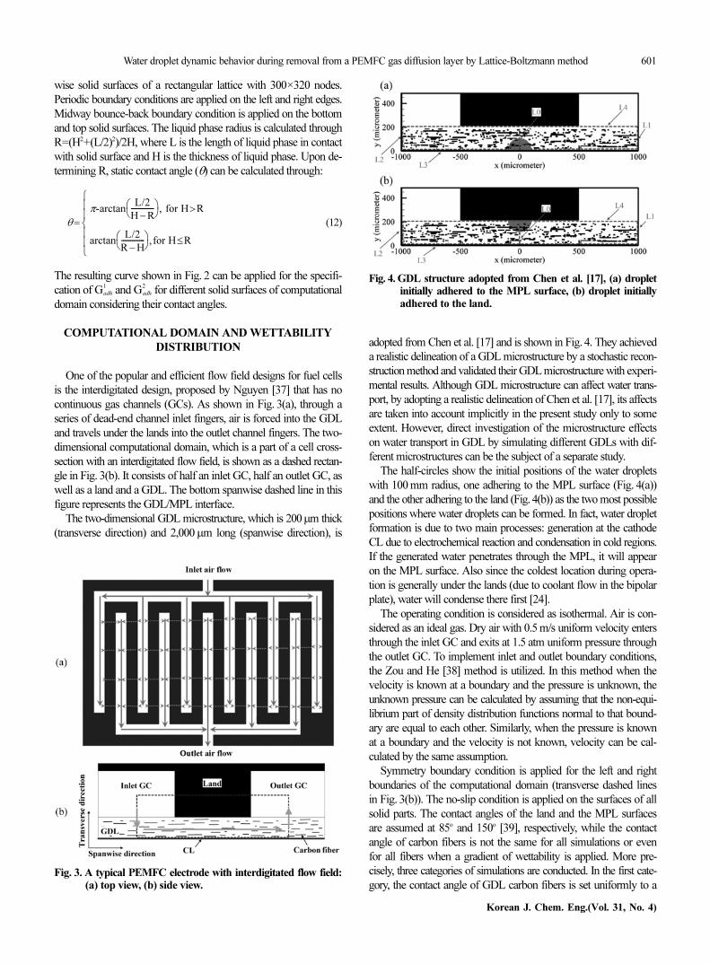
continuous gas channels (GCs). As shown in Fig. 3(a), through a
series of dead-end channel inlet fingers, air is forced into the GDL
and travels under the lands into the outlet channel fingers. The two-
dimensional computational domain, which is a part of a cell cross-
section with an interdigitated flow field, is shown as a dashed rectan-
gle in Fig. 3(b). It consists of half an inlet GC, half an outlet GC, as
well as a land and a GDL. The bottom spanwise dashed line in this
figure represents the GDL/MPL interface.
The two-dimensional GDL microstructure, which is 200µm thick
(transverse direction) and 2,000µm long (spanwise direction), is
adopted from Chen et al. [17] and is shown in Fig. 4. They achieved
a realistic delineation of a GDL microstructure by a stochastic recon-
struction method and validated their GDL microstructure with experi-
mental results. Although GDL microstructure can affect water trans-
port, by adopting a realistic delineation of Chen et al. [17], its affects
are taken into account implicitly in the present study only to some
extent. However, direct investigation of the microstructure effects
on water transport in GDL by simulating different GDLs with dif-
ferent microstructures can be the subject of a separate study.
The half-circles show the initial positions of the water droplets
with 100 mm radius, one adhering to the MPL surface (Fig. 4(a))
and the other adhering to the land (Fig. 4(b)) as the two most possible
positions where water droplets can be formed. In fact, water droplet
formation is due to two main processes: generation at the cathode
CL due to electrochemical reaction and condensation in cold regions.
If the generated water penetrates through the MPL, it will appear
on the MPL surface. Also since the coldest location during opera-
tion is generally under the lands (due to coolant flow in the bipolar
plate), water will condense there first [24].
The operating condition is considered as isothermal. Air is con-
sidered as an ideal gas. Dry air with 0.5 m/s uniform velocity enters
through the inlet GC and exits at 1.5 atm uniform pressure through
the outlet GC. To implement inlet and outlet boundary conditions,
the Zou and He [38] method is utilized. In this method when the
velocity is known at a boundary and the pressure is unknown, the
unknown pressure can be calculated by assuming that the non-equi-
librium part of density distribution functions normal to that bound-
ary are equal to each other. Similarly, when the pressure is known
at a boundary and the velocity is not known, velocity can be cal-
culated by the same assumption.
Symmetry boundary condition is applied for the left and right
boundaries of the computational domain (transverse dashed lines
in Fig. 3(b)). The no-slip condition is applied on the surfaces of all
solid parts. The contact angles of the land and the MPL surfaces
are assumed at 85o and 150o [39], respectively, while the contact
angle of carbon fibers is not the same for all simulations or even
for all fibers when a gradient of wettability is applied. More pre-
cisely, three categories of simulations are conducted. In the first cate-
gory, the contact angle of GDL carbon fibers is set uniformly to a
θ =
π-arctanL/2
H − R-------------⎝ ⎠⎛ ⎞ for H R>,
arctanL/2
R − H-------------⎝ ⎠⎛ ⎞ for H R≤,
⎩⎪⎪⎨⎪⎪⎧
Gadh
1
Gadh
2
Fig. 3. A typical PEMFC electrode with interdigitated flow field:(a) top view, (b) side view.
Fig. 4. GDL structure adopted from Chen et al. [17], (a) dropletinitially adhered to the MPL surface, (b) droplet initiallyadhered to the land.
602 G. R. Molaeimanesh and M. H. Akbari
April, 2014
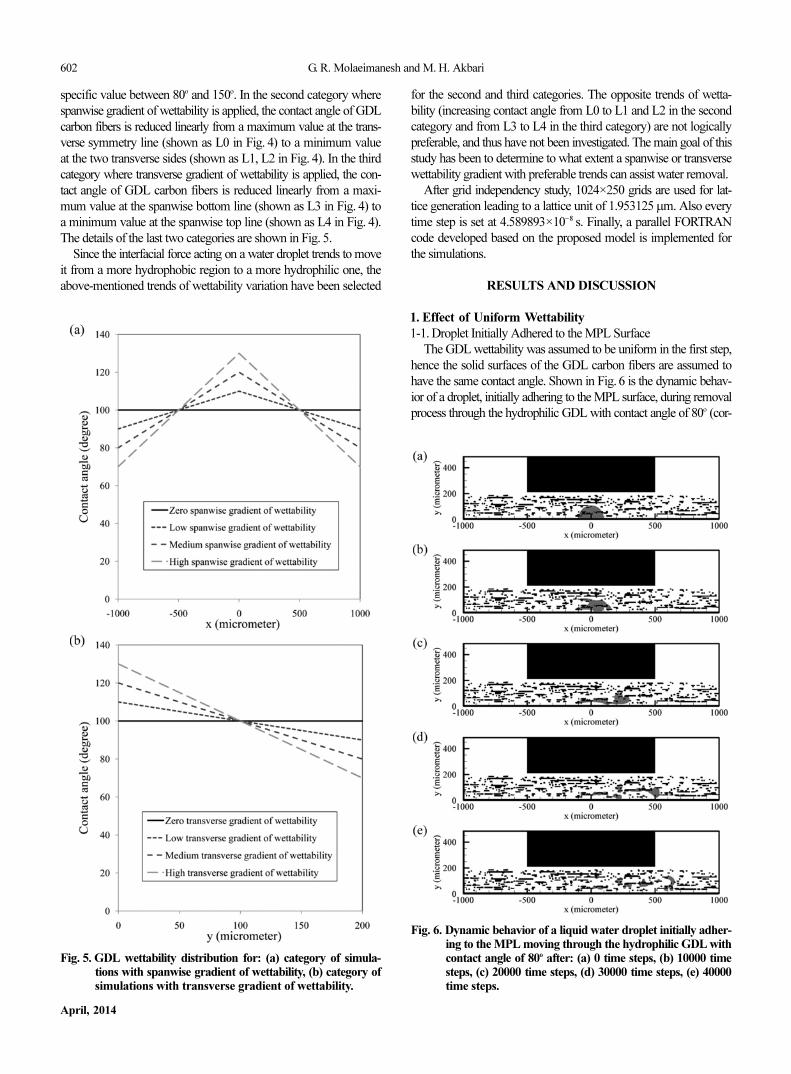
specific value between 80o and 150o. In the second category where
spanwise gradient of wettability is applied, the contact angle of GDL
carbon fibers is reduced linearly from a maximum value at the trans-
verse symmetry line (shown as L0 in Fig. 4) to a minimum value
at the two transverse sides (shown as L1, L2 in Fig. 4). In the third
category where transverse gradient of wettability is applied, the con-
tact angle of GDL carbon fibers is reduced linearly from a maxi-
mum value at the spanwise bottom line (shown as L3 in Fig. 4) to
a minimum value at the spanwise top line (shown as L4 in Fig. 4).
The details of the last two categories are shown in Fig. 5.
Since the interfacial force acting on a water droplet trends to move
it from a more hydrophobic region to a more hydrophilic one, the
above-mentioned trends of wettability variation have been selected
Fig. 5. GDL wettability distribution for: (a) category of simula-tions with spanwise gradient of wettability, (b) category ofsimulations with transverse gradient of wettability.
Fig. 6. Dynamic behavior of a liquid water droplet initially adher-ing to the MPL moving through the hydrophilic GDL withcontact angle of 80o after: (a) 0 time steps, (b) 10000 timesteps, (c) 20000 time steps, (d) 30000 time steps, (e) 40000time steps.
for the second and third categories. The opposite trends of wetta-
bility (increasing contact angle from L0 to L1 and L2 in the second
category and from L3 to L4 in the third category) are not logically
preferable, and thus have not been investigated. The main goal of this
study has been to determine to what extent a spanwise or transverse
wettability gradient with preferable trends can assist water removal.
After grid independency study, 1024×250 grids are used for lat-
tice generation leading to a lattice unit of 1.953125µm. Also every
time step is set at 4.589893×10⁻⁸ s. Finally, a parallel FORTRAN
code developed based on the proposed model is implemented for
the simulations.
RESULTS AND DISCUSSION
1. Effect of Uniform Wettability
1-1. Droplet Initially Adhered to the MPL Surface
The GDL wettability was assumed to be uniform in the first step,
hence the solid surfaces of the GDL carbon fibers are assumed to
have the same contact angle. Shown in Fig. 6 is the dynamic behav-
ior of a droplet, initially adhering to the MPL surface, during removal
process through the hydrophilic GDL with contact angle of 80o (cor-

Water droplet dynamic behavior during removal from a PEMFC gas diffusion layer by Lattice-Boltzmann method 603
Korean J. Chem. Eng.(Vol. 31, No. 4)
responding to a GDL without PTFE content). It is observed that
small droplets are separated from the initial droplet and stick to carbon
fibers. Since these small droplets spread on the surface of carbon
Fig. 7. Dynamic behavior of a liquid water droplet initially adher-ing to MPL moving through the hydrophobic GDL withcontact angle of 150o after: (a) 0 time steps, (b) 5000 timesteps, (c) 10000 time steps, (d) 15000 time steps, (e) 20000time steps, (f) 25000 time steps, (g) 30000 time steps, (h)35000 time steps.
Fig. 8. The time evolution of the ratio between mass of water inthe GDL and the initial droplet mass adhering to the MPLfor the GDLs with uniform wettability (contact angles be-tween 80o and 150o).
fibers due to their hydrophilic property, the inlet air flow can hardly
move them. After about 40000 time steps (each 5000 time steps is
almost 0.23 ms), the initial droplet sticks to a series of carbon fibers
and will not move any further.
Shown in Fig. 7 is the dynamic behavior of a droplet, initially
adhering to the MPL surface, during removal process through the
highly hydrophobic GDL with contact angle of 150o. Although the
contact angle of pure PTFE is 115o, this simulation under such hy-
drophobic conditions can be helpful for future attempts to reduce
GDL wettability with more hydrophobic materials. Our simulation
shows that at the beginning of the droplet motion it breaks into three
smaller droplets of an almost equal size. These smaller droplets,
unlike in the previous case (hydrophilic GDL), will not stick to car-
bon fibers and easily move between them.
The time evolution of the ratio between mass of water in the GDL
and the initial droplet mass adhering to the MPL, is presented in
Fig. 8 for various GDL contact angles. For GDL contact angles of
80o and 90o, the droplet cannot exit the GDL; thus no sharp reduction
of liquid water mass is seen for such non-hydrophobic cases. On the
contrary, a sharp drop in the corresponding curve is seen for hydro-
phobic cases, which indicates the exit of the water droplet from the
GDL. As the GDL contact angle increases, this sharp drop occurs
sooner and steeper. This implies that increasing the hydrophobicity of
the GDL will facilitate the removal of water droplet from the GDL
and will reduce the remaining mass of liquid water in the GDL.
Examining Fig. 8 also shows that the behavior of the water drop-
let does not change much when contact angle is 130o to 150o. This
indicates that increasing hydrophobicity beyond a critical value,
130o here, does not assist droplet removal any further. This obser-
vation is important when undesirable consequences of conventional
hydrophobic treatments are considered, such as their adverse effects
on the GDL gas permeability and electrical resistance [40]. In other
words, increasing the contact angle of GDL beyond a critical value
is not recommended. Finally, the initial slow reduction of water mass,
observed in Fig. 8, is a result of the removal of water in form of

604 G. R. Molaeimanesh and M. H. Akbari
April, 2014
vapor and very small droplets from the GDL at the beginning.
1-2. Droplet Initially Adhering to the Land
The dynamic behavior of a droplet, initially adhering to the land,
during removal process is shown in Fig. 9 for the hydrophilic GDL
with contact angle of 80o, which represents a GDL without PTFE
content. Simulation results show that the initial droplet tends to slide
on the land. During sliding motion, its lower part is separated and
sticks to carbon fibers. This is followed by a reconfiguration of the
small sticking droplet into an aerodynamic shape that minimizes
the pressure drag exerted by the gas flow. Consequently, the small
droplet is stabilized such that the gas flow will be unable to remove
it from its position in the GDL.
Meanwhile, the sliding portion of the initial droplet lifts off from
the land and sticks to the carbon fibers close by. This seems reason-
able since the land surface with a contact angle of 85o is slightly
more hydrophobic than these carbon fibers. This portion also stabi-
lizes in its position; therefore, no significant portion of the initial
droplet reaches the outlet GC.
The dynamic behavior of a droplet, initially adhering to the land,
during removal process is shown in Fig. 10 for the highly hydro-
phobic GDL with contact angle of 150o. The initial droplet easily
slides on the land; this ease of movement is partly due to the hydro-
phobicity of the carbon fibers and partly due to their simple struc-
ture on the GDL interface. Fig. 10 shows that a small fraction of
the initial droplet is trapped by an impeding carbon fiber structure
just beneath the land. Due to hydrophilic nature of the land surface
the sliding droplet will not lift off the land while entering the outlet
GC; this stage can be seen in Fig. 10(f). The overall result of the
wettability characteristics of the GDL and the land in this case is
that the droplet can be easily removed from the GDL. It appears
Fig. 9. Dynamic behavior of a liquid water droplet initially adher-ing to the land moving through the hydrophilic GDL withcontact angle of 80o after: (a) 0 time steps, (b) 5000 time steps,(c) 10000 time steps, (d) 15000 time steps, (e) 20000 time steps,(f) 25000 time steps.
Fig. 10. Dynamic behavior of a liquid water droplet initially adher-ing to the land moving through the hydrophobic GDL withcontact angle of 150o after: (a) 0 time steps, (b) 5000 timesteps, (c) 10000 time steps, (d) 15000 time steps, (e) 20000time steps, (f) 25000 time steps.

Water droplet dynamic behavior during removal from a PEMFC gas diffusion layer by Lattice-Boltzmann method 605
Korean J. Chem. Eng.(Vol. 31, No. 4)
that when droplet initially formed on the land, the role of land wetta-
bility is crucial.
Presented in Fig. 11 is the time evolution of the ratio between
mass of water in the GDL and the initial droplet mass adhering to
the land, for various GDL contact angles. For the GDL contact angle
of 80o the droplet cannot exit the GDL; thus no sharp reduction of
water mass is seen for this hydrophilic case. As the contact angle
of GDL increases, a sharp drop in the curve is observed to form
sooner and steeper, which indicates exiting of more liquid water
from the GDL at earlier stages. Fig. 11 also shows that the droplet
behavior is not altered much for the GDL contact angles of 130o to
150o. This suggests that increasing hydrophobicity beyond a cer-
tain value would not facilitate droplet removal any more. Thus, it
appears that an optimum PTFE content exists for which the best
performance may be achieved [40].
2. Effect of Spanwise Gradient of Wettability
In this section water droplet removal from four different GDLs
with different wettability conditions, but identical mean contact angle
of 100o, is simulated to investigate the effect of spanwise gradient
of wettability; one GDL is without gradient of wettability and the
other three GDLs are with low, medium and high spanwise gradient
of wettability as described in Fig. 5(a). It is clear that when span-
wise gradient of wettability exists, the interfacial force acting on
the droplet during its motion tends to move it from transverse center
line (L0 in Fig. 4) towards right side line (L1 in Fig. 4).
Fig. 12 shows the dynamic behavior of a liquid water droplet,
initially adhering to the MPL, during removal from the GDL with
high spanwise gradient of wettability (refer to Fig. 5(a)). Since hydro-
phobicity of the GDL reduces from the transverse center line (the
initial position of the droplet) towards the side lines (middle of the
outlet gas channel), the droplet easily starts moving from its initial
position. However, as the droplet moves toward the outlet GC, it
slows down due to an increase in the adhesion force acting on the
droplet by the carbon fibers. Interestingly, when it finally reaches
the outlet GC, some hydrophilic carbon fibers prevent the droplet
from moving through the channel; see Figs. 12(g)-(h).
Fig. 13 shows the dynamic behavior of a liquid water droplet,
initially adhering to the land, as it moves through the GDL with
Fig. 11. The time evolution of the ratio between mass of water inthe GDL and the initial droplet mass adhering to the landfor the GDLs with uniform wettability (contact angles be-tween 80o and 150o).
Fig. 12. Dynamic behavior of a liquid water droplet initially adher-ing to the MPL moving through the hydrophilic GDL withhigh spanwise gradient of wettability after: (a) 0 time steps,(b) 5000 time steps, (c) 15000 time steps, (d) 25000 timesteps, (e) 30000 time steps, (f) 45000 time steps, (g) 55000time steps, (h) 100000 time steps.

606 G. R. Molaeimanesh and M. H. Akbari
April, 2014
high spanwise gradient of wettability. Similar to the previous case,
the GDL contact angle reduces from 130o at the transverse center
line to 70o at the side lines (refer to Fig. 5(a)). This variation result
in a contact angle of 100o in the middle of these two lines (the trans-
verse location of the outlet GC left wall). Since the contact angle at
this location is greater than 90o, the droplet easily slides on the land
towards the outlet GC without a difficulty.
Fig. 14 shows the time evolution of the ratio between mass of
water in the GDL and the initial droplet mass during removal pro-
cess for the four mentioned GDLs. For each GDL, two cases are
considered where the initial droplet is placed either on the MPL or
the land. The simulation results for all four GDLs with the droplet
initially placed on the MPL are summarized in Fig. 14(a). It is ob-
served that GDL’s spanwise gradient of wettability will not facili-
tate removal of a droplet initially adhering to the MPL. Also surpris-
ingly, increasing GDL’s spanwise gradient of wettability will result
in a slightly slower removal process in this case. For this particular
GDL structure, the above statement can be justified as follows. The
maximum transverse component of gas velocity does not occur at
the centerline of the outlet GC (line L1 in Fig. 4) because of the
particular microstructure of the GDL considered here. This maxi-
mum transverse component of gas velocity rather occurs somewhere
between the land and centerline of the outlet GC. Hence, while the
GDL’s spanwise gradient of wettability pulls droplets towards the
centerline of the outlet GC, it is also pulling them away from the
region of maximum transverse component of gas velocity, which
could otherwise readily push the droplets out of the GDL and hence
facilitate water removal.
Fig. 14(b) shows that GDL’s spanwise gradient of wettability will
facilitate removal of a droplet initially adhering to the land (rather
than to the MPL) and increasing this gradient will further enhance the
removal process. This seems reasonable since by increasing GDL’s
Fig. 13. Dynamic behavior of a liquid water droplet initially adher-ing to the land moving through the hydrophobic GDL withhigh spanwise gradient of wettability after: (a) 0 time steps,(b) 5000 time steps, (c) 10000 time steps, (d) 15000 time steps,(e) 20000 time steps, (f) 25000 time steps.
Fig. 14. The time evolution of the ratio between mass of water inthe GDL and the initial droplet mass for the GDLs withdifferent spanwise gradients of wettability: (a) droplet ini-tially adhering to the MPL, (b) droplet initially adheringto the land.

Water droplet dynamic behavior during removal from a PEMFC gas diffusion layer by Lattice-Boltzmann method 607
Korean J. Chem. Eng.(Vol. 31, No. 4)
spanwise gradient of wettability, the interfacial force will push the
droplet on the land more strongly towards the outlet GC. In all cases
in which the droplet is initially adhering to the land, it moves through
Fig. 15. Dynamic behavior of a liquid water droplet initially adher-ing to the MPL moving through the hydrophilic GDL withhigh transverse gradient of wettability after: (a) 0 time steps,(b) 5000 time steps, (c) 10000 time steps, (d) 20000 time steps,(e) 25000 time steps, (f) 35000 time steps, (g) 45000 timesteps, (h) 80000 time steps.
Fig. 16. Dynamic behavior of a liquid water droplet initially adher-ing to the land moving through the hydrophobic GDL withhigh transverse gradient of wettability after: (a) 0 time steps,(b) 5000 time steps, (c) 10000 time steps, (d) 15000 time steps,(e) 20000 time steps, (f) 25000 time steps.
the GC while it adheres to the wall of the outlet GC.
3. Effect of Transverse Gradient of Wettability
To investigate the effect of GDL’s transverse gradient of wetta-
bility on water droplet removal, simulations are conducted for four
different GDLs with different wettability conditions, but with iden-
tical mean contact angle of 100o, in this section. One GDL is con-
sidered without gradient of wettability and the other three with low,
medium and high transverse gradient of wettability as described
previously in Fig. 5(b). It is clear that when transverse gradient of
wettability exists in the GDL, the interfacial force acting on the droplet
during its motion tends to move it from the bottom line (L3 in Fig.
4) towards the top line (L4 in Fig. 4).
Fig. 15 shows the dynamic behavior of a liquid water droplet,
initially adhering to the MPL, moving through the GDL with high
transverse gradient of wettability (refer to Fig. 5(b)). Since the hydro-
608 G. R. Molaeimanesh and M. H. Akbari
April, 2014
phobicity of GDL is reduced from the bottom line (where the water
droplet is initially placed) towards the top line (through which the
water droplet leaves the GDL), the droplet easily starts moving from
its initial position. However, due to decreasing of the contact angle
during its movement towards the outlet GC, the adhesion force acting
on the droplet by the carbon fibers will be increased, and hence it will
slow down. Similar to the case of Fig. 12, when the droplet reaches
the outlet GC some hydrophilic carbon fibers prevent it from exit-
ing the outlet GC as shown in Figs. 15(g)-(h).
Shown in Fig. 16 is the dynamic behavior of a liquid water droplet,
initially adhering to the land, as it moves through the GDL with
high transverse gradient of wettability (refer to Fig. 5(b)). Since the
droplet must slide on the land to reach the outlet GC in this case
and the carbon fibers on its path are highly hydrophilic, the largest
portion of the droplet will attach to the impeding carbon fibers and
only a small portion will reach the outlet GC.
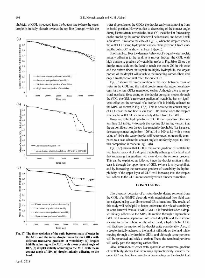
Fig. 17 shows the time evolution of the ratio between mass of
water in the GDL and the initial droplet mass during removal pro-
cess for the four GDLs mentioned earlier. Although there is an up-
ward interfacial force acting on the droplet during its motion through
the GDL, the GDL’s transverse gradient of wettability has no signif-
icant effect on the removal of a droplet if it is initially adhered to
the MPL, as shown in Fig. 17(a). This is because the contact angle
of GDL near the top line is less than 100o; hence when the droplet
reaches the outlet GC it cannot easily detach from the GDL.
However, if the hydrophobicity of GDL decreases from the bot-
tom line (L3 in Fig. 4) towards the top line (L4 in Fig. 4) such that
the carbon fibers near the top line remain hydrophobic (for instance,
decreasing contact angle from 120o at L4 to 100o at L5 with a mean
value of 110o), the water droplet will be removed more easily com-
pared to a case where the contact angle is uniformly equal to 110o;
this comparison is made in Fig. 17(b).
Fig. 17(c) shows that GDL’s transverse gradient of wettability
will hinder removal of a droplet if initially adhering to the land, and
that increasing this gradient will slow down the removal process.
This can be explained as follows. Since the droplet motion in this
case is through the upper layer of GDL (where it is hydrophilic),
and by increasing the transverse gradient of wettability the hydro-
philicity of the upper layer of GDL will increase; thus the droplet
will adhere to the GDL more severely which hinders its motion.
CONCLUSIONS
The dynamic behavior of a water droplet during removal from
the GDL of a PEMFC electrode with interdigitated flow field was
investigated using two-dimensional LB simulations. The results of
this study will be helpful to better understand the role of wettability
in water removal from a PEMFC GDL. It is found that when a drop-
let initially adheres to the MPL, its motion through a hydrophilic
GDL will involve separation into small droplets and their severe
sticking to carbon fibers; on the other hand, a hydrophobic GDL
will facilitate the motion of the droplet quite considerably. Also, if
a droplet initially adheres to the land, it will slide on the land while
moving through a hydrophilic GDL; and although some portions
will be separated and stick to carbon fibers, the remained portions
will easily pass the impeding carbon fiber.
Also, simulation of cases with spanwise or transverse gradient
of wettability shows that decreasing hydrophobicity towards the
outlet GC will lead to an interfacial force acting on the droplet that
Fig. 17. The time evolution of the ratio between mass of water inthe GDL and the initial droplet mass for the GDLs withdifferent transverse gradients of wettability: (a) dropletinitially adhering to the MPL with mean contact angle of100o, (b) droplet initially adhering to the MPL with meancontact angle of 110o, (c) droplet initially adhering to theland.

Water droplet dynamic behavior during removal from a PEMFC gas diffusion layer by Lattice-Boltzmann method 609
Korean J. Chem. Eng.(Vol. 31, No. 4)
generally eases its motion through the GDL. However, if the hydro-
phobicity gradient is such that the carbon fibers near the outlet GC
become hydrophilic, a droplet which has reached the outlet GC will
stick to carbon fibers and cannot actually exit to the outlet GC.
The main conclusions from this study can be summarized as fol-
lows:
1. Increasing the hydrophobicity of GDL (up to a threshold) will
facilitate the removal of water droplet from the GDL and will also
decrease the remaining mass of the initial droplet in the GDL.
2. GDL’s spanwise gradient of wettability cannot improve removal
of a droplet initially adhering to the MPL, while it will assist removal
of a droplet initially adhering to the land.
3. The effect of GDL’s transverse gradient of wettability on the
removal of a droplet initially adhering to the MPL is dependent on
wettability condition near the outlet GC. More specifically, if the
transverse gradient of wettability is such that the carbon fibers near
the outlet GC are hydrophobic, the water droplet will be removed
more easily. Otherwise, the transverse gradient of wettability will
hinder the removal of a droplet that initially adheres to the land.
NOMENCLATURE
: particle velocity in direction i of lattice [lu·ts−1]
cs : speed of sound in lattice [lu·ts−1]
: fluid-solid interaction force acting on a particle of type k [lm·
lu·ts−2]
: fluid-fluid interaction force acting on a particle of type k [lm·
lu·ts−2]
fi : density distribution function in direction i of lattice
: equilbrium density distribution function in direction i of lat-
tice
: density distribution function of component k in direction i
of lattice
: cohesion factor between components k and j
: adhesion factor of components k to the wall
H : thickness of droplet [lu]
L : length of droplet in contact with solid surface [lu]
P : pressure [lm·lu−1·ts−2]
R : droplet radius [lu]
: particle position vector [lu]
s : solid function in Eq. (5)
t : time [ts]
∆t : time step [ts]
: macroscopic velocity vector [lu·ts−1]
: equilibrium velocity vector of component k [lu·ts−1]
wi : weighting factor for direction i of lattice
Greek Symbols
θ : static contact angle
ρ : density [lm·lu−3]
σ : interfacial tension
τ : relaxation time [ts]
ψ k : inter-particle potential function of component k
Subscripts and Superscripts
i : direction i
k : component k
ref : refrence
Abbreviations
CL : catalyst layer
DDF : density distribution function
GC : gas channel
GDL : gas diffusion layer
LBM : Lattice-Boltzmann method
MPL : micro-porous layer
PEMFC : proton exchange membrane fuel cell
PTFE : polytetrafluoroethylene
SC : Shan and Chen
REFERENCES
1. T. H. Yang, G. Park, P. Pugazhendhi, W. Y. Lee and C. S. Kim,
Korean J. Chem. Eng., 19, 417 (2002).
2. J. E. Dawes, N. S. Hanspal, O. A. Family and A. Turan, Chem. Eng.
Sci., 64, 2781 (2009).
3. K. Jiao and X. Li, Prog. Energy Combust. Sci., 37, 221 (2011).
4. Y. Wang, K. S. Chen, J. Mishler, S. C. Cho and X. C. Adroher, Appl.
Energy, 88, 981 (2011).
5. M. A. Khan, B. Sundén and J. Yuan, J. Power Sources, 196, 7899
(2011).
6. S. Succi, The lattice boltzmann equation for fluid dynamics and be-
yond numerical mathematics and scientific computation, Claren-
don Press, Oxford (2001).
7. Y. Gao, X. Zhang, P. Rama, R. Chen, H. Ostadi and K. Jiang, Com-
put. Math. Appl., 65, 891 (2013).
8. L. Hao and P. Cheng, J. Power Sources, 195, 3870 (2010).
9. L. Hao and P. Cheng, J. Heat Mass Transfer, 53, 1908 (2010).
10. L. Hao and P. Cheng, Int. J. Heat Mass Transfer, 55, 133 (2011).
11. T. Koido, T. Furusawa and K. Moriyama, J. Power Sources, 175,
127 (2008).
12. P. Mukherjee, C. Y. Wang and Q. Kang, Electrochim. Acta, 54, 6861
(2009).
13. X. D. Niu, T. Munekata, S. A. Hyodo and K. Suga, J. Power
Sources, 172, 542 (2007).
14. Y. Tabe, Y. Lee, T. Chikahisa and M. Kozakai, J. Power Sources,
193, 24 (2009).
15. Y. Ben Salah, Y. Tabe and Y. Chikahisa, J. Power Sources, 199, 85
(2012).
16. Y. Ben Salah, Y. Tabe and Y. Chikahisa, Energy Procedia, 28, 125
(2012).
17. L. Chen, H. B. Luan, Y. L. He and W. Q. Tao, Int. J. Therm. Sci., 5,
132 (2012).
18. B. Han and H. Meng, J. Power Sources, 217, 268 (2012).
19. B. Han, J. Yu and H. Meng, J. Power Sources, 202, 175 (2012).
20. L. Hao and P. Cheng, J. Power Sources, 190, 435 (2009).
21. J. Park and X. Li, J. Power Sources, 178, 248 (2008).
22. J. Nam and M. Kaviany, Int. J. Heat Mass Transfer, 46, 4595 (2003).
23. F. Y. Zhang, X. G. Yang and C. Y. Wang, J. Electrochem. Soc., 153,
A225 (2006).
24. M. M. Mench, Fuel Cell Engines, Wiley, New Jersey (2008).
25. M. M. Daino and S. G. Kandlikar, Int. J. Hydrog. Energy, 37, 5180
(2012).
ci
Fadh
k
Fcoh
k
f
i
eq
f
i
k
Gcoh
kj
Gadh
kj
r
U
uk eq,
610 G. R. Molaeimanesh and M. H. Akbari
April, 2014
26. P. Zhou and C. W. Wu, J. Power Sources, 195, 1408 (2010).
27. P. K. Sinha and C. Y. Wang, Electrochim. Acta, 52, 7936 (2007).
28. P. K. Sinha and C. Y. Wang, Chem. Eng. Sci., 63, 1081 (2008).
29. S. Chen and G. D. Doolen, Annu. Rev. Fluid. Mech., 30, 329 (1998).
30. X. Shan and H. Chen, Phys. Rev. E, 47, 1815 (1993).
31. P. L. Bhatnagar, E. P. Gross and M. Krook, Phys. Rev., 94, 511
(1954).
32. A. K. Gunstensen, D. H. Rothman, S. Zaleski and G. Zanetti, Phys.
Rev. A, 43, 4320 (1991).
33. M. R. Swift, W. R. Osborn and J. M. Yeomans, Phys. Rev. Lett., 75,
830 (1995).
34. A. A. Mohamad, Lattice boltzmann method-fundamentals and engi-
neering applications with computer codes, Springer, Heidelberg
(2011).
35. M. C. Sukop and D. T. Thorne, Lattice boltzmann modeling, an
introduction for geoscientists and engineers, Springer, Heidelberg
(2007).
36. P. Yuan and L. Schaefer, Phys. Fluids, 18, 042101 (2006).
37. T. V. Nguyen, J. Electrochem. Soc., 143, 103 (1996).
38. Q. Zou and X. He, Phys. Fluids, 9, 1591 (1997).
39. E. C. Kumbur, K. Y. Sharp and M. M. Mench, J. Power Sources,
168, 356 (2007).
40. G. Velayutham, J. Kaushik, N. Rajalakshmi and K. S. Dhathathreyan,
Fuel Cells, 7, 314 (2007).