waste thermal heat pump - universiti malaysia sarawak thermal heat pump (24pgs).pdf · waste...
TRANSCRIPT
WASTE THERMAL HEAT PUMP
Nicholas Han Tin Huat
Bachelor of Engineering with Honours
(Mechanical and Manufacturing Engineering)
2010
UNIVERSITI MALAYSIA SARAWAK
R13a
BORANG PENGESAHAN STATUS THESIS
Judul: WASTE THERMAL HEAT PUMP
SESI PENGAJIAN: 2009/2010
Saya NICHOLAS HAN TIN HUAT
(HURUF BESAR)
mengaku membenarkan tesis * ini disimpan di Pusat Khidmat Maklumat Akademik, Universiti
Malaysia Sarawak dengan syarat-syarat kegunaan seperti berikut:
1. Tesis adalah hakmilik Universiti Malaysia Sarawak.
2. Pusat Khidmat Maklumat Akademik, Universiti Malaysia Sarawak dibenarkan membuat salinan
untuk tujuan pengajian sahaja.
3. Membuat pendigitan untuk membangunkan Pangkalan Data kandungan Tempatan.
4. Pusat khidmat Maklumat Akademik, Universiti Malaysia Sarawak dibenarkan membuat salinan
tesis ini sebagai bahan pertukaran antara institusi pengajian tinggi.
5. ** Sila tandakan ( √ ) di kota yang berkenaan
SULIT (Mengandungi maklumat uang berdarjah keselamatan atau kepentingan
Malaysia seperti yang termaktub di dalam AKTA RAHSIA RASMI 1972).
TERHAD (Mengandungi maklumat TERHAD yang telah ditentukan oleh organisasi/
Badan di mana penyelidikan dijalankan).
TIDAK
TERHAD
Disahkan oleh
(TANDATANGAN PENULIS) (TANDATANGAN PENYELIA)
Alamat tetap:
No 18 Jln Bernam 11,_____ EN. ISKANDAR BIN JOBLI
Taman Bernam 35900_____ Nama Penyelia
Tanjong Malim Perak._____
Tarikh: Tarikh:
CATATAN * Tesis dimaksudkan sebagai tesis bagi Ijazah Doktor Falsafah, Sarjana dan Sarjana Muda.
** Jika tesis ini SULIT atau TERHAD, sila lampirkan surat daripada pihak berkuasa/organisasi berkenaan dengan
menyatakan sekali sebab dan tempoh tesis ini perlu dikelaskan sebagai SULIT dan TERHAD.
√
APPROVAL SHEET
The following final year project:
Title: Waste Thermal Heat Pump
Author: Nicholas Han Tin Huat
Matrics Number: 16822
Is hereby read and approved by:
En.Iskandar bin Jobli Date
(Supervisor)

WASTE THERMAL HEAT PUMP
NICHOLAS HAN TIN HUAT
Thesis is submitted to
Faculty of Engineering, University Malaysia Sarawak
In Partial Fulfillment of the Requirements
For the Degree of Bachelor of Engineering
With Honours (Mechanical and Manufacturing Engineering) 2010

To my beloved family and friends

i
ACKNOWLEDGEMENT
I would like to thank and express my appreciation to my supervisor, En. Iskandar
bin Jobli of University Malaysia Sarawak for his guidance and encouragement rendered
to me in completing my final year project successfully. Your suggestion and advice
makes my works simpler and easier and I appreciate your effort very much.
I also would like to thank the supporting staff of UNIMAS Engineering Department
especially Mr. Azaman and Ms. Zila for their commitment and support to me in
providing the necessary facilities. Without their help I will not have been able to
complete my research with ease.
Finally, I would like to thank my family especially my mother who always give me
the encouragements and financial support throughout my study in UNIMAS. Last but
not least, thank you to Ong Sue Ann, my girlfriend who have inspired me and
encouraged me to work an extra mile than others.

iv
TABLE OF CONTENTS
Page
APPROVAL SHEET
ACKNOWLEDGEMENT i
ABSTRAK ii
ABSTRACT iii
TABLE OF CONTENT iv
LIST OF FIGURES viii
LIST OF TABLES xiii
LIST OF ABBREVIATION xv
Chapter 1 INTRODUCTION
1.1 Introduction to Biomass 1
1.2 Introduction to Heat 2
1.3 Introduction to Heat Pump 3
1.4 Problem Statement 5
1.5 Objectives 5
1.6 Scope of Study 6
Chapter 2 LITERATURE REVIEW
2.1 Types of Biomass Conversion Process 7
v
2.1.1 Thermal Conversion 8
2.1.1.1 Combustion 8
2.1.1.2 Gasification 10
2.1.1.3 Pyrolysis 12
2.1.2 Biochemical Conversion 12
2.1.2.1 Aerobic Digestion (Composting) 12
2.1.2.1.1 Heat Produced from Composting 14
2.1.2.3 Anaerobic Digestion 15
2.2 Introduction to Heat Pump System 17
2.2.1 A Typical Heat Pump Cycle 18
2.2.1.1 Air-Source Heat Pump in Heating Cycle 19
2.2.1.2 Air-Source Heat Pump in Cooling Cycle 20
2.2.1.3 Air-Source Heat Pump in Defrost Cycle 21
2.2.2 Heat Pump Components 22
2.2.2.1 Evaporator and Condenser Coils 22
2.2.3 The Efficiency of a Heat Pump 23
2.2.4 Refrigerants 26
2.2.4.1 Types of Refrigerants 27
2.2.4.2 Refrigerant Selection Consideration 27

vi
2.2.5 Types of Heat Pump Systems 27
2.2.5.1 Air-Source Heat Pumps 28
2.2.5.2 Water-Source Heat Pumps 30
2.2.5.3 Refrigerators 34
2.2.5.4 Air-Conditioners 36
Chapter 3 METHODOLOGY
3.1 Introduction 39
3.2 Evaporator Heat Exchanger Design 41
3.3 Experiment Materials 43
3.3.1 Materials Preparation 43
3.3.2 Materials Moisture Content 45
3.3.3 Materials Mass Reduction Before and After Experiment 46
3.4 System Design 46
3.5 Types of Systems 48
3.5.1 A System with a Heat Extraction System 49
3.5.2 A System without a Heat Extraction System 50
3.6 Measuring Instruments 51
3.6.1 Data Logger 52
3.6.2 Personal Computer (PC) 52
vii
3.6.3 Tracer DAQ Data Logger Software 53
Chapter 4 RESULTS AND DISCUSSION
4.1 Introduction 55
4.2 Compost Temperature Analysis for Control System 56
4.3 Compost Temperature Analysis for Heat Extraction System 59
4.4 Double Stage Heating Analysis 63
4.5 Moisture Content Analysis 67
4.6 Power Output Analysis 68
Chapter 5 CONCLUSION AND RECOMMENDATION
5.1 Conclusion 73
5.2 Recommendation 74
REFERENCES 76
APPENDIX 80
xiii
LIST OF TABLES
Table Title Page
Table 1 Moisture Content Analysis 67
Table 2 Average Power Output per kg Dry Grass 69

viii
LIST OF FIGURES
Figure Title Page
Figure 1 Types of Biomass Sources 2
Figure 2 A Heat Pump System
4
Figure 3 Thermochemical and biochemical processes
classification
7
Figure 4 External heating increases the temperature of
wood
9
Figure 5 Pyrolysis starts and the chemical structure of
wood is decomposed. Light pyrolysis products
volatilize from the surface
9
Figure 6 Combustion starts. Pyrolysis products react
with oxygen and produce more heat, causing a
strongly growing chain reaction
9
Figure 7 Processes in Gasification 10
Figure 8 Comparison of anaerobic and aerobic system 14
ix
Figure 9 Path of Anaerobic Digestion 16
Figure 10 Air-Source Heat Pump in Heating Cycle 19
Figure 11 Air-Source Heat Pump in Cooling Cycle 20
Figure 12 Picture of (a) Indoor / outdoor coil and (b)
Water coil
23
Figure 13 Reversed heat engine (Heat Pump) 24
Figure 14 Picture of (a) Packaged unit and (b) Split
System
28
Figure 15 Picture of ground coupled heat pumps
(GCHP)
30
Figure 16 Picture of ground water heat pumps (GWHP) 31
Figure 17 Picture of surface water heat pumps (SWHP) 31
Figure 18 Typical Tube-in-Tube Heat Exchanger (Water
Coil)
33
Figure 19 A kitchen refrigerator and its four main
components
34
Figure 20 Refrigerator in single stage vapor compression
cycle
34

x
Figure 21 Air-conditioner in single stage vapor
compression cycle
37
Figure 22 Various air-conditioning process 38
Figure 23 Flow chart for the experiment procedure 40
Figure 24 The picture of container box 1 without grass
clipping
41
Figure 25 The picture of container box 2 without grass
clipping
42
Figure 26 The picture of container box 1 filled with
grass clipping
44
Figure 27 The picture of container box 2 filled with
grass clipping
45
Figure 28 A schematic diagram of a heat pump system 47
Figure 29 Container with heat recovery system 49
Figure 30 Container without heat recovery system 50
Figure 31 The picture of a thermocouple placed inside
the container
51
Figure 32 The picture of Data Logger 52

xi
Figure 33 The picture of BenQ laptop model JoybookR
45
53
Figure 34 TracerDAQ Data Logger Software in Strip
Chart Pattern
54
Figure 35 Save Options 54
Figure 36 Compost Temperature for the first cycle 56
Figure 37 Compost Temperature for the second cycle 57
Figure 38 Compost Temperature in Container 1 for the
first cycle
59
Figure 39 Compost Temperature in Container 2 for the
first cycle
59
Figure 40 Compost Temperature in Container 1 for the
second cycle
60
Figure 41 Compost Temperature in Container 2 for the
second cycle
60
Figure 42 Picture of Compost (a) Before and (b) After
Composting
62
Figure 43 Water Temperature for first cycle 63
Figure 44 Water Temperature for second cycle 64

xii
Figure 45
Picture of Double Stage Heat Extraction
System
65
Figure 46 Single vs Double Stage Heating (1st Cycle) 68
Figure 47 Single vs Double Stage Heating (2nd Cycle) 69

xv
LIST OF ABBREVIATION
q - rate of heat production (W)
M - mass of composting material (kg)
Cp - specific heat of composting material (cal per g per °C)
T - rate of temperature change (°C per h)
COP - coefficient of performance
TH - sink temperature
TL - source temperature
QH - heat from hot reservoir
QC - heat from cold reservoir
W - work input from the compressor
Mn - moisture content (%) of material
WW - wet weight of the sample
Wd - weight of the sample after drying
W - change in grass weight
Wi - weight of grass before decomposition

xvi
Wf - weight of grass after decomposition
dQ/dt - heat transfer rate ( kJ/s )
m - mass flow rate ( kg/s )
Cp - constant pressure for the refrigerant kJ/kgK
Tout - water temperature at the outlet ( ºC )
Tin - water temperature at the inlet ( ºC )
ii
ABSTRACT
The objective of this experiment is to develop a heat exchanger system that used
the biomass decomposition process heat as the source of energy. The system will be
design and construct based on the operating principles of geothermal heat pumps and the
feasibility and flexibility of the system will be analyzed. The design is comprised of a
heat exchanger coil that is placed at the bottom of the container with water circulates
through the coil to extract heat from the decomposition process. The proposed system
will be compared to a control system, a system without heat exchanger coil to see the
effect of heat exchanger coil on the biomass temperature and also its decomposition rate.
This experiment also introduced the double stage heating system to increase the
temperature difference of the water between the inlet and outlet of the system. The
moisture content of the grass in the first cycle is 71.5% and 74.8% for the second cycle.
The average power output per kg dry matter produced from the double stage heating for
the first and second cycle is 0.41 Watt/kg and 0.47 Watt/kg.

iii
ABSTRAK
Objektif eksperimen ini adalah bagi membangunkan sistem penukar haba yang
menggunakan proses penguraian biojisim haba sebagai sumber tenaga. Sistem itu akan
direka dan dibina berdasarkan prinsip operasi pam haba geoterma dan sistem praktikal
serta kelonggarannya akan dianalisis. Reka bentuk meliputi satu gegelung penukar haba
yang terletak di dasar bekas dengan air mengalir dalam gegelung untuk mengekstrak
haba daripada proses penguraian. Sistem yang dicadangkan akan dibanding dengan satu
sistem kawalan, satu sistem tanpa gegelung penukar haba untuk melihat kesannya
terhadap suhu biojisim dan juga kadar penguraiannya. Eksperimen ini juga
memperkenalkan sistem pemanasan peringkat berganda untuk meningkatkan perbezaan
suhu air antara serokan dan kedai sistem. Kandungan lembapan rumput untuk kitaran
pertama ialah 71.5% dan 74.8% untuk kitaran kedua. Output kuasa purata setiap kg
bahan kering yang dihasilkan daripada pemanasan peringkat berganda untuk kitaran
pertama dan kedua ialah 0.41 Watt / kg dan 0.47 Watt / kg.
1
CHAPTER 1
INTRODUCTION
1.1 Introduction to Biomass
In this 21st century, the evolution of technolgy and population growth has
increased the demand for power supply. Hence energy has become one of the most
important issue to be discussed in this project. Energy can be divided into two main
types which is renewable energy such as biomass, hydro, geothermal and wind
energy. The another type is non-renewable energy such as petroleum, natural gas
and coal. The inadequate of energy supply, the fluctuating of foreign fossil fuel and
also the environment conditions have force us to exploit for alternatives energy
sources available on our planet.
In the mean time, biomass energy is one of the options available to support and
sustain the the expanding energy demand from the users. The word ‘biomass’ tell us
this form of energy is derived from a biological materials derived from living or
recently living organisms. Actually, biomass substance such as plant matter,
garbage, crops, landfill and biofuels have a chemical energy which can be converted
into heat energy by various means to produced heat to generate electricity. Biomass
energy is derived from three distinct energy sources for exmaple wood, waste and

2
alcohol fuels (Wikipedia, Biomass, 2009). Biomass is a renewable energy because
its supplies are continously and not limited.
Figure 1 : Types of Biomass Sources (Biomass, 2008)
1.2 Introduction to Heat
Energy can exist in numerous forms such as thermal, mechanical, kinetic,
potential, electric, magnetic, chemical and nuclear which their sum constitutes the
total energy E of a system. The first law of thermodynamic states that energy can be
neither created or destroyed during a process where it can only change forms. This
law also known as the conservation of energy principle (Cengel & Boles, 2006, p.
70).
Heat energy is transferred between two systems if there is a temperature
difference between them. In case if both systems is at the same temperature, no heat
transfer will take places and this is called adiabatic process. A process can be
adiabatic if the system is well insulated or both the system and the surroundings are
3
at the same temperature but the energy content and the temperature of the system
may still changed by others mean such work(Cengel & Boles, 2006, p. 61).
Heat is transferred by three mechanism for example conduction, convection
and radiation. Conduction is the mode of heat transfer in which energy exchange
takes place from the region of high temperature to that of low temperature by the
kinetic motion or direct impact of molecules. Convection is the transfer of energy
between a solid surface and the adjacent fluid that is in motion. Radiation is the
transfer of energy due to the emission of the elctromagnetic waves known as
photons (Ozisik, 1985, p. 2).
1.3 Introduction to Heat Pump
Heat is a form of energy that is transfer between two systems by virtue of a
temperature difference (Cengel & Boles, 2006, p. 60). Heat can only be transfer
between two system from a higher temperature medium to a lower temperature
medium and impossible to exist for the vice versa condition. This heat transfer
process occurs in nature witout require any devices.
To enable a heat to transfer from a low-temperature medium to a high-
temperature medium, a special devices called heat pumps is required to allow this
process to take place. In fact heat pump is a reverse cycle of a heat engine that
moves heat from a low temperature heat source to a higher temperature heat sink
using mechanical work. The common examples are food refrigerators and freezers,
air conditioners and reversible-cycle heat pumps for providing thermal comfort
(Wikipedia, Heat Pump, 2009).
4
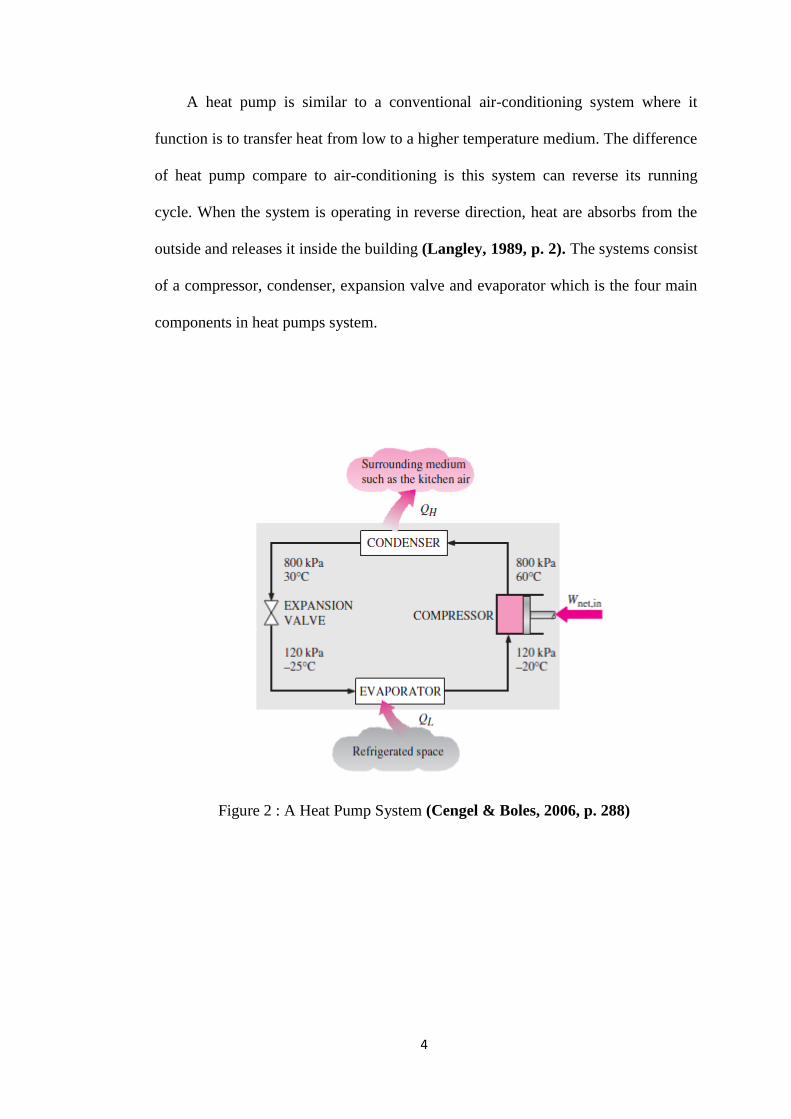
A heat pump is similar to a conventional air-conditioning system where it
function is to transfer heat from low to a higher temperature medium. The difference
of heat pump compare to air-conditioning is this system can reverse its running
cycle. When the system is operating in reverse direction, heat are absorbs from the
outside and releases it inside the building (Langley, 1989, p. 2). The systems consist
of a compressor, condenser, expansion valve and evaporator which is the four main
components in heat pumps system.
Figure 2 : A Heat Pump System (Cengel & Boles, 2006, p. 288)