washington state department of ecology environmental...
TRANSCRIPT

Washington State Department of Ecology Environmental Assessment Program Standard Operating Procedure for Purging and Sampling Monitoring Wells plus Guidance on Collecting Samples for Volatiles and other Organic Compounds Version 2.0 Author - Pamela B. Marti Date - Unit Approval Martha Maggi, Groundwater/Forests & Fish Unit Supervisor Date - Section Approval – Will Kendra, Statewide Coordination Section Manager Date - QA Approval - William R. Kammin, Ecology Quality Assurance Officer Date - EAP078 APPROVED: 1/27/2014 Signatures on File
X:\EA PROGRAM\ECYEAPSOP\Approved SOPs\ECY_EAP_SOP_PurgingSamplingMonitoringWell_V2_EAP078.docx_1/27/14_Page 2
Please note that the Washington State Department of Ecology’s Standard Operating Procedures (SOPs) are adapted from published methods, or developed by in-house technical and administrative experts. Their primary purpose is for internal Ecology use, although sampling and administrative SOPs may have a wider utility. Our SOPs do not supplant official published methods. Distribution of these SOPs does not constitute an endorsement of a particular procedure or method. Any reference to specific equipment, manufacturer, or supplies is for descriptive purposes only and does not constitute an endorsement of a particular product or service by the author or by the Department of Ecology. Although Ecology follows the SOP in most instances, there may be instances in which Ecology uses an alternative methodology, procedure, or process.

X:\EA PROGRAM\ECYEAPSOP\Approved SOPs\ECY_EAP_SOP_PurgingSamplingMonitoringWell_V2_EAP078.docx_1/27/14_Page 3
SOP Revision History Revision Date Rev
number Summary of changes Sections Reviser(s)
1/27/2014 2.0 Minor edits all sections, added Appendix B
All, added Append B
Pam Marti

X:\EA PROGRAM\ECYEAPSOP\Approved SOPs\ECY_EAP_SOP_PurgingSamplingMonitoringWell_V2_EAP078.docx_1/27/14_Page 4
TABLE OF CONTENTS Page 1.0 Purpose and Scope................................................................................................................5 2.0 Applicability ………………................................................................................................5 3.0 Definitions............................................................................................................................6 4.0 Personnel Qualifications/Responsibilities……....................................................................7 5.0 General List of Equipment and Supplies .............................................................................7 6.0 Summary of Procedures .......................................................................................................9 6.1 Project Planning …………………………………………………….............................9 6.2 Sample Equipment Selection ........................................................................................10 6.3 Field Work Preparation .................................................................................................11 6.4 Purging and Sampling Procedures ……………………………………………….........13 6.5 Low Volume and Poor Recovery Wells ………………………………………….........18 7.0 Records Management...........................................................................................................20 8.0 Quality Control and Quality Assurance...............................................................................21 9.0 Safety................................................................................................................................... 22 10.0 References..........................................................................................................................22 Appendix A – Example field forms Appendix B – Collecting Samples for Volatile Organics and other Organic Compounds

X:\EA PROGRAM\ECYEAPSOP\Approved SOPs\ECY_EAP_SOP_PurgingSamplingMonitoringWell_V2_EAP078.docx_1/27/14_Page 5
Environmental Assessment Program Standard operating procedure for purging and sampling monitoring wells.
1.0 Purpose and Scope 1.1 The Environmental Assessment Program (EAP) is responsible for measuring,
assessing, and reporting information about the environmental condition and health of Washington’s land and water resources. This information is used by resource managers, policymakers, and others to help protect and manage Washington’s environment. As such there is a need to document and ensure that consistent and scientifically defensible practices, procedures, and techniques are used by EAP staff, and that the data and information they provide are of consistent and high quality.
1.2 The goals for collecting groundwater samples from monitoring wells are varied, but can include: characterizing ambient conditions, defining the nature and extent of groundwater problems; or determining trends in contaminant concentrations with time, location, or both.
1.3 Groundwater measurements and samples should be as representative of in situ conditions as possible. Several factors such as changes in temperature, pressure, and exposure to air can alter the groundwater chemistry during the sampling process. This SOP summarizes the general procedures and practices that EAP staff use to help ensure that representative groundwater samples are collected when sampling wells that do not typically have installed or dedicated pumps (e.g. monitoring wells).
2.0 Applicability
2.1 This SOP applies to EAP staff collecting and handling groundwater samples from monitoring wells or other wells that do not have a dedicated down-hole pump. It provides general information to help guide field staff in proper purging and sampling techniques. Field staff are encouraged to supplement the information in this SOP by reviewing the large body of existing literature on the science of groundwater sampling (see reference list). Alternative procedures are allowed as long as they are properly documented in the project Quality Assurance Project Plan (QAPP), and provide scientifically valid and legally defensible groundwater data.
2.2 Field staff should be familiar with other standard procedures related to activities described in this SOP (e.g. measurement of groundwater levels, use of GPS equipment, etc). Depending on the analyte(s) being sampled, there can also be special sample pre-treatment, filtering, post-treatment, and collection procedures that must be adhered to (see appendices for additional details). Digital versions of all EAP SOP’s can be found on Ecology’s quality assurance page at http://www.ecy.wa.gov/programs/eap/quality.html.

X:\EA PROGRAM\ECYEAPSOP\Approved SOPs\ECY_EAP_SOP_PurgingSamplingMonitoringWell_V2_EAP078.docx_1/27/14_Page 6
3.0 Definitions
3.1 Aquifer – An underground layer of saturated permeable/porous rock or sediments (e.g. gravel, sand or silt) that is capable of storing and releasing water to wells and springs.
3.2 Dissolved Oxygen – The relative amount of oxygen that is dissolved or carried in water.
3.3 Data Quality Objectives (DQO’s) – Data Quality Objectives are qualitative and quantitative statements derived from systematic planning processes that clarify study objectives, define the appropriate type of data, and specify tolerable levels of potential decision errors that will be used as the basis for establishing the quality and quantity of data needed to support decisions (USEPA, 2006).
3.4 Depth-to-Water – The measured depth to the top of the groundwater surface in a well. Also referred to in this SOP as water level measurement.
3.5 EAP – Environmental Assessment Program
3.6 Ecology – Washington State Department of Ecology
3.7 EIM – Environmental Information Management System. A searchable database of environmental information (e.g. water quality results, etc) developed and maintained by the Washington State Department of Ecology.
3.8 Field Data Sheets – Weather resistant sheets (“Rite in the Rain” ® writing paper) used to document all field activities, sample data, methods, and observations for each collection site.
3.9 GPS - Global Positioning System
3.10 Measuring Point – A fixed and clearly marked point on a well casing from which depth-to-water/water level measurements are made. Fixed water level measuring points are established to ensure data comparability over time and among field samplers.
3.11 ORP – Oxidation-Reduction Potential. The electric potential required to transfer electrons from one compound or element (the oxidant) to another compound (the reductant). Used as a qualitative measure of the state of oxidation in water.
3.12 pH – A measure of the acidity or alkalinity of water. A pH value of 0 to 7 indicates that an acidic condition is present, while a pH value of 7 to 14 indicates a basic or alkaline condition. A pH of 7 is considered to be neutral. Since the pH scale is logarithmic, a water sample with a pH of 8 is ten times more basic than one with a pH of 7.

X:\EA PROGRAM\ECYEAPSOP\Approved SOPs\ECY_EAP_SOP_PurgingSamplingMonitoringWell_V2_EAP078.docx_1/27/14_Page 7
3.13 Quality assurance project plan (QAPP) – A written plan that describes how a study will be conducted and its results assessed.
3.14 Specific Conductance (SC) – A measure of the water’s ability to conduct an electrical current. Specific conductance is related to the concentration and charge of dissolved ions in water.
3.15 Static Water Level – The level of water in a well that is not being affected by the withdrawal or injection of water.
3.16 Water table elevation – The elevation of the top water surface of an unconfined aquifer.
4.0 Personnel Qualifications/Responsibilities
4.1 Staff new to groundwater sampling should review the most recent USGS National Field Manual for the Collection of Water-Quality Data (USGS, 1997); The Essential Handbook of Ground-Water Sampling (Nielsen, 2007), or an equivalent, for background information on the principles and techniques of groundwater monitoring. Staff should have a working understanding of the groundwater monitoring needs for their particular project prior to preparing the project Quality Assurance Project Plan (QAPP) and beginning field work.
4.2 Field staff should have a detailed working knowledge of the project QAPP to ensure that credible and useable data are collected, and should be briefed by the field lead on the sampling goals and objectives prior to arriving at the site.
4.3 This document supplements but does not replace the need for on-the-job training. All field staff should be familiar with the sampling equipment and instruments being used. The field lead is responsible for ensuring that all field staff adhere to prescribed sampling methods when conducting field work.
4.4 EAP staff who conduct groundwater sampling are responsible for complying with this SOP and the requirements of the EAP safety manual - particularly Chapter 1 ‘General Field Work’ and the following sections of Chapter 2: ‘Groundwater Sampling and Water-Level Measurements’ and ‘Hazardous Waste Sites’ (Ecology, 2009).
5.0 General List of Equipment and Supplies 5.1 Sample Measuring and Collecting Equipment 5.1.1 Field data sheets 5.1.2 Water level measuring equipment (e.g. calibrated electric water level meter,
graduated steel tape) 5.1.3 Water quality meters and probes (e.g. pH, SC, DO, temperature, ORP) 5.1.4 Probe calibration standards/reagents 5.1.5 Field analytical devices (e.g. spectrophotometer, turbidimeter, etc.) 5.1.6 Flow cell

X:\EA PROGRAM\ECYEAPSOP\Approved SOPs\ECY_EAP_SOP_PurgingSamplingMonitoringWell_V2_EAP078.docx_1/27/14_Page 8
5.1.7 Pump (submersible, peristaltic, bladder) 5.1.8 Power supply (generator, battery) 5.1.9 Extension cord 5.1.10 Sample tubing and connectors 5.1.11 Sample containers/bottles 5.1.12 Sample preservatives 5.1.13 Sample filters/tubing adapters (analyte specific) 5.1.14 Laboratory grade deionized water for quality assurance samples 5.1.15 Coolers with ice or ice packs 5.1.16 55-gallon barrels (to store and properly dispose of contaminated purge water) 5.2 Cleaning and Disinfecting Supplies 5.2.1 Deionized water 5.2.2 Laboratory grade soap (Liquinox®) 5.2.3 Dilute chlorine bleach solution 5.2.4 Cleaning solvents, if applicable 5.3 Safety Equipment 5.3.1 Nitrile gloves 5.3.2 Hearing protection 5.3.3 Safety goggles 5.3.4 Hard hat 5.3.5 First aid kit 5.3.6 Orange vest, Ecology issued 5.3.7 Traffic cones 5.3.8 Traffic signs, if applicable
5.4 Miscellaneous Equipment 5.4.1 Well location map 5.4.2 All applicable SOPs 5.4.3 Field paper work: property owner contact information, field data sheets, sample
bottle labels and tags, chain-of-custody sheets. 5.4.4 Pencils, pens, etc. 5.4.5 Permanent marking pen or paint stick (for marking water level measuring point) 5.4.6 Calculator 5.4.7 Well keys, if applicable 5.4.8 Compass 5.4.9 GPS unit 5.4.10 Digital camera 5.4.11 Paper towels or clean rags 5.4.12 Plastic garbage bags 5.4.13 Plastic sheeting for ground cover 5.4.14 Buckets, plastic 5-gallon 5.4.15 1-liter container (to calibrate purge volume/rate) 5.4.16 Stop watch 5.4.17 Field bag (containing rain gear, rubber boots, work gloves, etc.)

X:\EA PROGRAM\ECYEAPSOP\Approved SOPs\ECY_EAP_SOP_PurgingSamplingMonitoringWell_V2_EAP078.docx_1/27/14_Page 9
5.4.18 Hand cleaner 5.4.19 Product/Water interface probe, if applicable 5.5 Tools 5.5.1 Steel hand measuring tape (engineer scale) 5.5.2 Socket wrench set 5.5.3 Allen wrench set 5.5.4 Pipe wrenches 5.5.5 Crescent wrenches 5.5.6 Set of screwdrivers 5.5.7 File 5.5.8 Knife 5.5.9 Hammer 5.5.10 Pliers 5.5.11 Hack saw 5.5.12 Crow bar/manhole hook 5.5.13 Shovel 5.5.14 Machete 5.5.15 Whiskbroom 5.5.16 Spare well cover bolts/nuts 5.5.17 Spare well caps/plugs 5.5.18 Spare pad locks/keys 5.5.19 Wire brush 5.5.20 WD-40 (to be used away from the well head) 5.5.21 Bailing device (e.g. cooking baster, peristaltic pump with battery) 5.5.22 Flashlight 5.5.23 Spare batteries (e.g. electric-tape, GPS, flashlight) 5.5.24 Tape (duct tape/electrical tape) 5.5.25 Well tagging equipment 6.0 Summary of Procedure
6.1 Project Planning
6.1.1 A Quality Assurance Project Plan (QAPP) must be completed and approved before collecting water quality samples for analysis. The QAPP details project goals, data quality objectives, quality assurance procedures, sample handling requirements (container requirements, preservation, holding times), and field and laboratory procedures. Guidelines for Preparing Quality Assurance Project Plans for Environmental Studies (Lombard, 2004) provides detailed guidance on developing EAP project plans. A QAPP can reference SOPs for standard field monitoring or measurement procedures; however, non-standard procedures or deviations should be described in detail in the QAPP.
6.1.2 Detailed information should be collected for each well location whenever practical, including: well construction logs, previous water level data, site access

X:\EA PROGRAM\ECYEAPSOP\Approved SOPs\ECY_EAP_SOP_PurgingSamplingMonitoringWell_V2_EAP078.docx_1/27/14_Page 10
agreements, and other relevant information about the well being sampled. An example of a well reconnaissance field form is included in Appendix A.
6.1.3 Well location and construction information for wells that are sampled should be entered into Ecology’s Environmental Information Management (EIM) system database.
6.1.3.1 If the well hasn’t been previously inventoried, use a GPS receiver when first visiting the well to define a preliminary latitude and longitude coordinate as described in SOP EAP013, Determining Coordinates via Hand-Held GPS Receivers (Janisch, 2006). The field-collected coordinates can be refined using mapping tools when entering the well into the EIM system.
6.1.3.2 If the well hasn’t been assigned a Department of Ecology unique well ID tag, then it should be tagged as described in EAP SOP081 Procedures for Tagging Wells (Pitz, 2011). Well tags are available from Ecology’s Water Resources Program. Securely attach the tag to the well casing, or other permanent, easily-seen fixture of the well. Once a well is tagged, complete the well tag form and submit to Ecology’s Water Resource Program along with a copy of the well log.
6.2 Sample Equipment Selection
6.2.1 Selecting equipment for purging and sampling a well requires site and project specific considerations to ensure that all collected samples meet the project objectives and data quality requirements. Groundwater chemistry can be altered by changes in temperature, pressure, and exposure to air that are brought on by the sampling process. Therefore, it is imperative to select sample equipment and follow sampling procedures that minimize these changes. General considerations for equipment selection are discussed below. More detailed information can be found in documents such as the USGS National Field Manual for the Collection of Water-Quality Data, and Nielsen (2007) The Essential Handbook of Ground-Water Sampling.
6.2.2 Factors to consider when selecting sample equipment include: the analytes being evaluated, the type and location of well being sampled, physical characteristics of the well (diameter and total depth), depth to water, the amount of water to be purged, geology adjacent to the screened interval and the groundwater chemistry.
6.2.2.1 Sample equipment must be compatible with the analytes being sampled. This includes the materials the sample equipment is made of, as well as its operation.
6.2.2.2 Sampling equipment can be a source of sample bias or error. Equipment that contacts the sample should be made of inert material to the extent possible. Materials commonly used include high quality stainless steel (pumps), and various forms of plastic (pumps, pump tubing and connectors). As explained by Nielsen (2007), sample materials should not sorb analytes from samples, desorb previously sorbed analytes into samples, leach matrix components that could

X:\EA PROGRAM\ECYEAPSOP\Approved SOPs\ECY_EAP_SOP_PurgingSamplingMonitoringWell_V2_EAP078.docx_1/27/14_Page 11
affect analyte concentrations or cause artifacts, or be physically or chemically degraded by the water chemistry.
6.2.2.3 In general, the softer or more flexible forms of metal or plastic have been found to be more reactive than rigid forms. For example, soft tubing (e.g. silicone, polyvinyl chloride - Tygon®) is found to be more gas permeable and sorptive of organic compounds. It is suitable for sampling inorganic analytes only. The more rigid tubing (e.g. polytetrafluorethylene (Teflon®), polyethylene, and propylene) appear to offer greater performance over other materials for both inorganic and organic analytes (Table 1).
Table 1: General guidelines for selecting equipment on the basis of construction material and target analytes (USGS 1997)
Material Description Inorganic Organic
Plastics Polytetrafluorethylene (Teflon® or Teflon-lined polyethylene)
Chemically inert for most analytes.
Yes (Potential source of
fluoride)
Yes (Sorption of some
organics)
Polypropylene Relatively inert for inorganic analytes. Yes Do not use.
Polyethylene Relatively inert for inorganic analytes. Yes Do not use.
Polyvinyl chloride (PVC)
Relatively inert for inorganic analytes. Yes Do not use.
Silicone (Silastic) Very porous. Relatively inert of most inorganic analytes.
Yes (Potential source of
silica) Do not use.
Nylon Relatively inert for inorganic analytes. Yes Do not use.
Metals
Stainless Steel, 316-grade (SS 316)
SS-316 metal having the greatest corrosion resistance. (Used for submersible pump casings)
Yes (Potential source of
Cr, Ni, Fe, and possibly Mn and Mo
if corroded).
Yes (Do not use if
corroded).
Stainless Steel, 304-grade (SS 304)
Similar to SS-316, but less corrosion resistant. Do not use.
Yes (Do not use if
corroded). Other metals: brass, iron, copper, aluminum, and galvanized and carbon steel
Do not use. (except as noted for isotopes)
Yes (Do not use if
corroded).
6.2.2.4 Pumps transport water from depth to the land surface by two methods, suction lift or positive pressure. The pumping mechanism for most suction-lift pumps (e.g. peristaltic and centrifugal pumps) is at land surface. Positive-pressure pumps (e.g. submersible and bladder) are placed below the static water level. Pump

X:\EA PROGRAM\ECYEAPSOP\Approved SOPs\ECY_EAP_SOP_PurgingSamplingMonitoringWell_V2_EAP078.docx_1/27/14_Page 12
selection is analyte dependant. In general, suction lift pumps are not recommended for sampling volatile organics because of the vacuum that is created at the intake to draw the sample to the land surface. The vacuum can result in the loss of volatile organics or other dissolved gases.
6.2.2.5 The physical characteristics of a well may also dictate equipment selection. Smaller diameter wells are becoming increasingly common in groundwater investigations. Such wells limit the potential range of equipment that can be used for sample collection (e.g. peristaltic pump, small diameter bladder pump or bailer).
6.2.2.6 The depth to water may also dictate equipment selection. All sample pumps have a defined lift capability. This is the ability of the equipment to move water from the static water level depth to the top of the well casing. For example the lift capability of suction-based pumps (peristaltic and centrifugal pumps) is about 25 feet. Depth to water also effects pump operation, since the pumping rate typically decreases with increased depth to water.
6.2.2.7 Being able to control the pumping rate is an important consideration when selecting sample equipment. Sampling rates should be high enough to fill sample containers efficiently and with minimal exposure to the atmosphere, but low enough to minimize sample alteration by agitation or aeration. This is especially important for sensitive analytes, such as volatile organic compounds and trace metals, which should be taken at low flow rates.
6.3 Field Work Preparation
6.3.1. Prior to sampling, inventory consumable field supplies such as disposable gloves, calibration standards, tubing, filters, etc. Order necessary supplies. Allow ample time for delivery.
6.3.2. Arrangements must be made with Ecology’s Manchester Environmental Laboratory before sampling. The Manchester Environmental Laboratory (MEL) Laboratory User's Manual (Ecology, 2008) contains detailed guidance on the planning steps necessary to request, track, ship, and analyze water quality samples collected in the field.
6.3.2.1. To notify the lab submit a Pre-sampling Notification Form and a Sample Container Request Form a minimum of 2 weeks prior to sampling. For large projects the lab should be informed 4-6 weeks prior to sampling.
6.3.2.2. Coordinate with the lab regarding any special arrangements such as contract lab analysis, special courier or delivery of samples.
6.3.2.3. Inventory sample bottles when they arrive to ensure the lab provided the correct type and number.

X:\EA PROGRAM\ECYEAPSOP\Approved SOPs\ECY_EAP_SOP_PurgingSamplingMonitoringWell_V2_EAP078.docx_1/27/14_Page 13
6.3.3. Establish the order the wells will be sampled. Sample order is either based on logistics or the known or suspected water quality of a sample location. For contaminated sites, wells should be sampled in order of increasing chemical concentrations (known or anticipated). This minimizes the possibility for cross-contamination of the sample equipment.
6.3.3.1. A few days before a planned sampling event contact the property owner, property operator or resident to confirm the sampling date and time and to discuss any site access issues.
6.3.3.2. Before going in the field prepare field data sheets for each well/sample location. It can be helpful to bring previous sample data for each well such as water level, pump intake placement, pump rate, total purge time, stabilized field parameter values, etc. Other sample paperwork should also be filled out as much as possible. Paperwork for a sample event typically includes: bottle labels and tags, and a Manchester Lab Chain-of-Custody/Lab Analysis Required Form (LAR). Examples of field data sheets are provided in Appendix A.
6.3.3.3. Field data sheets, bottle labels/tags, and laboratory paperwork should include the following information: station name and ID, laboratory number, requested analysis, and sample preservation method if applicable.
6.3.4. Inspect all equipment and verify that water quality field meters are in good working order, calibrate properly, and are fully charged. Calibration procedures are normally outlined in the meter user’s manual.
6.3.5. Field equipment, especially equipment being placed in a well, that is going to be reused must be properly cleaned, disinfected, or decontaminated prior to and after use in each well. Cleaning procedure depends on the equipment being used (water level equipment, field parameter probes, down well sample equipment) and the type of well being sampled (e.g. observation well, regulated facility monitoring well).
6.3.5.1. It is recommended that gloves (Nitrile) be worn when cleaning sample equipment. This will help maintain sanitary conditions of the cleaned equipment and will protect the sampler from the cleaning products being used. When not in use, equipment should be placed on a clean surface, such as a clean plastic sheet. If the equipment is not re-used immediately it should be wrapped in plastic sheeting or aluminum foil. Equipment should never be placed on bare soil prior to using it in a well.
6.3.5.2. Water level measuring equipment: rinse the probe and any submerged tape with deionized water before and after use in a well. Wipe or air dry. If the well is suspected or known to be contaminated, the probe and any submerged tape should be wiped with a disinfectant-soaked towel or washed in a 0.1-0.2% laboratory grade soap (e.g. Liquinox) solution, followed by a tap water and deionized water rinse.

X:\EA PROGRAM\ECYEAPSOP\Approved SOPs\ECY_EAP_SOP_PurgingSamplingMonitoringWell_V2_EAP078.docx_1/27/14_Page 14
6.3.5.3. Water quality field probes may be rinsed with deionized water between sample locations. If the probes are slow to respond and additional cleaning is needed, then the probes should be cleaned and maintained according to the manufacturer’s instructions.
6.3.5.4. Down well equipment, such as a submersible pump, should be washed in a laboratory grade soap (e.g. Liquinox) solution. Use a brush to scrub the exterior of the sample equipment. Flush the equipment with the 0.1-0.2% soap solution, then with tap water. Rinse with deionized water. If the pump can be disassembled, wash the separate parts in the detergent solution with a brush, followed by a tap water and deionized water rinse. Parts of the sample equipment that are difficult to submerge while cleaning, like a pumps electrical cable, can be wiped down with a disinfectant-soaked towel and then rinsed thoroughly with deionized water.
6.3.5.5. If the equipment is used in a contaminated well, additional cleaning may be required. The equipment may need a chemical rinse (e.g. acetone, nitric acid, methanol, isopropyl alcohol) depending on what analytes are being sampled. Rinse the equipment with deionized water. Place the equipment on a clean surface to air dry.
6.3.5.6. Equipment that is difficult to clean, such as pump tubing, should be replaced between sample locations. As mentioned previously pump tubing has the potential to provide a source of error because of the amount of contact with the sampled water. Therefore to help prevent possible cross-contamination it is advisable not to reuse sample tubing between sample locations. For long-term projects tubing may be dedicated to a well, but should not be used at other locations.
6.4. Purging and Sampling Procedures
6.4.1. All groundwater sampling follows the same basic standard procedures. These generally include checking and setting up the field sample equipment, collecting an initial water level measurement, installing sample equipment in the well, purging the well at a low flow rate, properly collecting, preserving and labeling all samples, and safely delivering the samples to the lab. Each step should be followed with care to ensure that collected groundwater samples meet the objectives and data quality requirements of the project.
6.4.2. Upon arriving at a well, set out safety equipment such as traffic cones and signs as needed.
6.4.3. Check the site for hazardous conditions, either physical or chemical.
6.4.4. If needed, spread clean plastic sheeting on the ground around the well to keep sample equipment clean.

X:\EA PROGRAM\ECYEAPSOP\Approved SOPs\ECY_EAP_SOP_PurgingSamplingMonitoringWell_V2_EAP078.docx_1/27/14_Page 15
6.4.5. Set up and field check sample equipment: water level meter, water quality meters and flow cell, selected pump and power supply, etc.
6.4.5.1. Wear clean disposable powder-free gloves (e.g. Nitrile) when handling all equipment used for collecting and processing samples.
6.4.5.2. If you haven’t already done so, calibrate field water quality meters according to the manufacturer’s instruction. Field parameters should be measured in a closed-atmosphere flow cell. If for some reason it’s not possible to use a flow cell at a particular location, it should be noted on the field data sheet.
6.4.5.3. If a gasoline-powered generator is used for the pump power supply, locate it as far from the well head or sample collection area as possible, preferably downwind.
6.4.6. Remove the well cover and cap. For monitoring wells on regulated facilities you will probably need a key.
6.4.6.1. If the well has not been sampled before, establish and document a water level measuring point using the procedures described in SOP EAP052, Manual Well Depth and Depth-to-Water Measurements (Marti 2009).
6.4.6.2. If the well is equipped with a pressure transducer or other down well instrumentation carefully note its position. Remove the instrumentation from the well according to SOP EAP074, Use of Submersible Pressure Transducers during Groundwater Studies (Sinclair and Pitz 2010). Note the removal time on the field data sheet.
6.4.7. Measure the static water level according to SOP EAP052 (Marti, 2009). Record the water level value, date, and time on the well specific field data sheet (Appendix A). The water level should be measured twice to confirm a stable and accurate measurement. The water level should be measured before inserting any other field equipment into the well.
6.4.7.1. If the well is suspected or known to have free floating product the water level and product thickness should be measured with an interface probe.
6.4.8. It can be helpful to know the amount of standing water in a well, particularly for projects where the purge water needs to be managed and properly disposed. To calculate the amount of standing water in one well volume, use the following information: measured water level, well diameter and total depth. The amount of standing water can be calculated using a variety of methods. One equation is:
Well volume: V = 0.041 x HD2 = ____ gallons, where V is volume of water in the well, in gallons, H is height of water column in well (i.e. total well depth – measured depth to water), in feet, and D is the inside diameter of the well casing, in inches

X:\EA PROGRAM\ECYEAPSOP\Approved SOPs\ECY_EAP_SOP_PurgingSamplingMonitoringWell_V2_EAP078.docx_1/27/14_Page 16
6.4.9. If the well is not equipped with a dedicated sampling system, install a decontaminated pump (e.g. submersible, bladder) or pump tubing (e.g. peristaltic). Slowly lower the equipment through the water column to avoid stirring up particulates.
6.4.9.1. If the well has been sampled before, the final pump intake should be placed at the same depth as used in previous sample events. Record the intake depth on the field data sheets.
6.4.9.2. If the well has not been previously sampled, position the pump intake at a depth prescribed by the project manager/field lead. In most cases the pump intake is set near or within the screened or open interval of the well. The final intake depth depends on the project objectives and should be specified in the QAPP.
6.4.10. Once the pump or pump tubing has been placed in the well, slowly lower the water level probe back into the well to measure water levels throughout purging. This is particularly important for low yield wells.
6.4.11. If the well has been sampled before, review past field data sheets for purge rates, total purge time, stabilized field parameter values, and amount of drawdown if any, prior to sample collection.
6.4.12. Start purging. Set the pump controller to the desired pumping rate. Depending on the target analytes pumping rates can vary from no greater than 1 L/min to as little as 150 mL/min.
6.4.12.1. Use water level measurements to help establish the optimum pump rate (which should not exceed 1L/min for low-flow sampling techniques). Purging should not cause a significant drawdown in the well. Significant drawdown is considered to be 5 percent of the total height of the water column or depth to the top of the screen. If unacceptable drawdown occurs at the initial set pumping rate, gradually decrease the pump rate until the water level stabilizes at an acceptable level. Record the final pump rate on the field data sheet.
6.4.12.2. Use the manufacturer supplied pump regulator rather than a secondary in-line valve system or other after-market device to adjust the pump flow. Managing the flow rate with an after-market device can cause sample agitation and alteration.
6.4.13. Purge water from wells that are not on regulated facilities or related to site cleanup work may be discharged directly to the ground as long as the water is not contaminated. Direct the purge water away from the wellhead and work area. Purge water from wells associated with a regulated facility or cleanup site that is contaminated should be collected and disposed of in accordance with Washington State regulations (Chapter 173-303-400 WAC).
6.4.14. During purging and sample collection the flow should be a smooth, solid stream of water with no air or gas bubbles in the tubing or flow cell. Gradually adjust the pumping rate to eliminate bubbles if present.

X:\EA PROGRAM\ECYEAPSOP\Approved SOPs\ECY_EAP_SOP_PurgingSamplingMonitoringWell_V2_EAP078.docx_1/27/14_Page 17
6.4.15. Once the flow is constant begin monitoring field parameter values in a flow cell at regular intervals (e.g. 2 to 5 minutes). The frequency of these measurements depends on the pump rate and the estimated time for the field parameters to stabilize. At a minimum, there should be a complete exchange of water in the flow cell between measurements.
6.4.16. Record the field parameter values, time of measurement, water level, and if tracking, the amount of purge water discharged. Note and provide qualifying remarks if parameter readings are anomalous or unstable due to instrument problems. Record observations on the pumped water’s appearance (e.g. clarity, odor, etc.) during purging and sampling.
6.4.17. Continue purging until all field parameters stabilize as specified in 6.3.18 or in the project specific QAPP. Monitored field parameters for EAP studies include but are not limited to pH, specific conductance, dissolved oxygen, and water temperature. Field parameters should be specified in the project QAPP.
6.4.18. Field parameters are considered stable when 3 consecutive readings fall within the following stabilization criteria:
pH ± 0.1 standard units Specific Conductance ± 10.0 μmhos/cm for values < 1000 μmhos/cm ± 20.0 μmhos/cm for values > 1000 μmhos/cm Dissolved Oxygen ± 0.05 mg/L for values < 1 mg/L ± 0.2 mg/L for values > 1 mg/L Temperature ± 0.1° Celsius ORP ± 10 millivolts
6.4.18.1. If sampling for metals, turbidity should be measured and have either stabilized or be below 10 NTUs. Turbidity readings should be below 5 NTUs if metals samples will not be filtered.
6.4.19. Once field parameters stabilize conduct any end of purge field parameter analysis (e.g. confirmation of low dissolved oxygen, alkalinity, iron) as specified in the project QAPP.
6.4.20. Collect samples once field parameters stabilize and any other field data has been collected. Do not stop or significantly change the pumping rate during the final phase of purging or while sampling. Purging and sample withdrawal should form a continuous process.
6.4.21. Samples should be collected in a specific order as determined in the project QAPP. The order of sample collection, processing and preservation for specific analytes should be adhered to consistently throughout a project. The recommended sequence for sample collection and processing is often based on logistics for maintaining sample integrity.
X:\EA PROGRAM\ECYEAPSOP\Approved SOPs\ECY_EAP_SOP_PurgingSamplingMonitoringWell_V2_EAP078.docx_1/27/14_Page 18
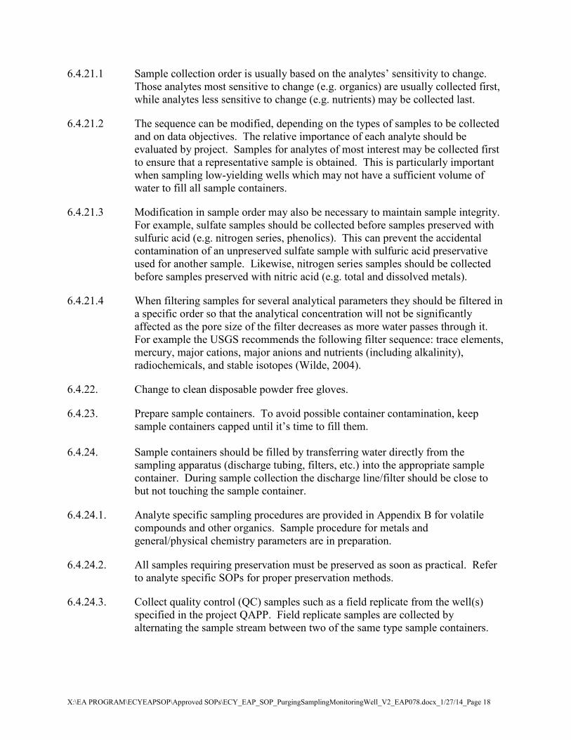
6.4.21.1 Sample collection order is usually based on the analytes’ sensitivity to change. Those analytes most sensitive to change (e.g. organics) are usually collected first, while analytes less sensitive to change (e.g. nutrients) may be collected last.
6.4.21.2 The sequence can be modified, depending on the types of samples to be collected and on data objectives. The relative importance of each analyte should be evaluated by project. Samples for analytes of most interest may be collected first to ensure that a representative sample is obtained. This is particularly important when sampling low-yielding wells which may not have a sufficient volume of water to fill all sample containers.
6.4.21.3 Modification in sample order may also be necessary to maintain sample integrity. For example, sulfate samples should be collected before samples preserved with sulfuric acid (e.g. nitrogen series, phenolics). This can prevent the accidental contamination of an unpreserved sulfate sample with sulfuric acid preservative used for another sample. Likewise, nitrogen series samples should be collected before samples preserved with nitric acid (e.g. total and dissolved metals).
6.4.21.4 When filtering samples for several analytical parameters they should be filtered in a specific order so that the analytical concentration will not be significantly affected as the pore size of the filter decreases as more water passes through it. For example the USGS recommends the following filter sequence: trace elements, mercury, major cations, major anions and nutrients (including alkalinity), radiochemicals, and stable isotopes (Wilde, 2004).
6.4.22. Change to clean disposable powder free gloves.
6.4.23. Prepare sample containers. To avoid possible container contamination, keep sample containers capped until it’s time to fill them.
6.4.24. Sample containers should be filled by transferring water directly from the sampling apparatus (discharge tubing, filters, etc.) into the appropriate sample container. During sample collection the discharge line/filter should be close to but not touching the sample container.
6.4.24.1. Analyte specific sampling procedures are provided in Appendix B for volatile compounds and other organics. Sample procedure for metals and general/physical chemistry parameters are in preparation.
6.4.24.2. All samples requiring preservation must be preserved as soon as practical. Refer to analyte specific SOPs for proper preservation methods.
6.4.24.3. Collect quality control (QC) samples such as a field replicate from the well(s) specified in the project QAPP. Field replicate samples are collected by alternating the sample stream between two of the same type sample containers.

X:\EA PROGRAM\ECYEAPSOP\Approved SOPs\ECY_EAP_SOP_PurgingSamplingMonitoringWell_V2_EAP078.docx_1/27/14_Page 19
6.4.24.4. Collect any additional QC samples before leaving the site. These may include field blanks (e.g. filter, equipment, transport). The types and numbers of quality control samples should be specified in the project QAPP.
6.4.25. Label sample containers and immediately place in an ice filled cooler. Samples must remain at or below 6°C throughout handling, storage, and shipping. Do not freeze samples.
6.4.26. Record sample date and time, final water level, and total purge volume on the field data sheet. Record any final observations or comments related to sample collection.
6.4.27. Follow the procedures in the project QAPP or Manchester Lab Manual for sample handling and management (e.g. chain of custody, sample courier service or any special shipping requirements or restrictions).
6.4.27.1. Be conscious of analytical holding times and minimize the time between sampling and delivery to the laboratory.
6.4.28. If the well is equipped with a transducer or other down well instrumentation that was removed during sampling, replace the equipment according to SOP EAP074, Use of Submersible Pressure Transducers during Groundwater Studies (Sinclair and Pitz 2010). Note the reinstall time on the field data sheet,
6.4.29. When all work at the well site is complete, properly close and secure the well.
6.4.30. Note any physical changes to the well on the field data sheets, such as erosion or cracks in the protective concrete pad or alteration to the well casing.
6.4.31. All equipment used to collect groundwater samples should be cleaned or disinfected as previously described. Store the equipment for transport to the next sample location or at the conclusion of the field study.
6.5. Low Volume and Poor Recovery Wells - Purging and Sampling Procedures
6.5.1. Even with a low pumping rate, some wells experience significant drawdown or in extreme cases may even purge dry. Slow recovering wells or wells that purge dry require extra care in order to be purged and sampled with minimal disturbance to the water column and fine materials in and around the well screen.
6.5.2. For low volume and poor recovery wells, review past field data sheets if available for previous purge rates, amounts of drawdown, and purge volume prior to sample collection.
6.5.3. Measure the well’s water level as described in steps 6.4.6. and 6.4.7.
6.5.4. If you suspect the well may be low yielding, calculate the amount of standing water in one well volume as described in step 6.4.8.

X:\EA PROGRAM\ECYEAPSOP\Approved SOPs\ECY_EAP_SOP_PurgingSamplingMonitoringWell_V2_EAP078.docx_1/27/14_Page 20
6.5.5. If the well is not equipped with a dedicated sampling system, install a decontaminated pump or pump tubing. Slowly lower the equipment through the water column to avoid stirring up particulates. The final pump intake depth should be near the bottom of the screened interval. To prevent stirring up particulates it is important not to touch the well bottom. Record the intake depth on the field data sheet.
6.5.6. Once the pump or pump tubing is in place, slowly lower the water level probe back into the well. It is important to frequently measure the water level throughout purging in low volume or poor recovery wells to enable the pump rate to be adjusted downward if necessary.
6.5.7. Start purging at a rate less than 0.5 liter per minute if the pump capacity allows. Record the pump rate on the field data sheet.
6.5.8. At regular intervals record field parameter values, water level, time of measurement, and amount of purge water discharged. Allow at least one complete exchange of water in the flow cell between measurements. Note and provide qualifying remarks if parameter readings are anomalous, the water level is dropping or if at some point the water level stabilizes. Record observations on the pumped waters appearance (e.g. clarity, odor, etc.) during purging and sampling.
6.5.9. Continue purging until field parameters stabilize per section 6.4.18. Attempts should be made to avoid purging low yielding wells dry. However, if this is not possible shut the pump off and allow the well to recover at least once before collecting samples. This generally constitutes an adequate purge, and the well can be sampled as soon as it has recovered sufficiently to produce an adequate volume of water to fill the sample containers. If time permits, purge the well a second time and allow it to recover before sampling. Samples should be collected within 24 hours of the final purge/recovery cycle.
6.5.9.1. It should be noted that there can be significant alterations in groundwater chemistry when a well is purged dry and allowed to recover before sampling. Groundwater chemistry can change as formation water surrounding or entering the screened interval of the well is exposed to air which can affect volatile organics and redox sensitive analytes. Increased turbidity can also be an issue when sampling metals and some general chemistry parameters (Nielsen, 2007).
6.5.10. Collect samples once field parameters stabilize and any end of purge analysis has been conducted.
6.5.10.1. If the well has been purged dry and allowed to recover, field parameters should be measured after sample collection if there is an adequate volume of water.
6.5.11. Sample containers should be filled in the order specified in the project QAPP. However, when sampling low-yielding wells which may not have a sufficient volume of water to fill all the sample containers, the relative importance of each analyte should be evaluated. Samples for analytes of most interest should be

X:\EA PROGRAM\ECYEAPSOP\Approved SOPs\ECY_EAP_SOP_PurgingSamplingMonitoringWell_V2_EAP078.docx_1/27/14_Page 21
collected first to ensure a representative sample is obtained. Discuss with the lab the minimum volume of sample needed for each analyte.
6.5.12. Fill, preserve, label and store sample containers as described in steps 6.4.24. through 6.4.27. Follow analyte specific sampling procedures which are provided in Appendix B for volatile compounds and other organics. Sample procedure for metals and general/physical chemistry parameters are in preparation.
6.5.13. Record sample date and time, final water level, and total purge volume on the field data sheet. Record any final observations or comments related to sample collection such as elapsed time for complete purge of the well and recovery rate of the well.
6.5.14. Follow the procedures in the project QAPP or Manchester Lab Manual for sample handling and management (e.g. chain of custody, sample courier service or any special shipping requirements or restrictions). Be conscious of analytical holding times and minimize the time between sampling and delivery to the laboratory.
6.5.15. Replace any down well instrumentation according to EAP074, Use of Submersible Pressure Transducers during Groundwater Studies (Sinclair and Pitz 2010). Note the reinstall time on the field data sheet.
6.5.16. Properly close and secure the well.
6.5.17. Note any physical changes to the well on the field data sheets, such as erosion or cracks in the protective concrete pad or alteration to the well casing.
6.5.18. All equipment used to collect groundwater samples should be cleaned or disinfected as previously described. Store the equipment for transport to the next sample location or at the conclusion of the field study
7.0 Records Management 7.1 Monitoring wells that EAP samples must be documented to enable information
about their location, construction, and subsequent monitoring data to be archived in Ecology’s Environmental Information Management (EIM) system and well log imaging databases. Consult the EIM help documents for a list of the well specific metadata required by EIM.
7.2 Station information and monitoring notes should be documented, during each site visit on site specific field data sheets. Examples are presented in Appendix A. All field entries should be neat and concise. The field lead is responsible for reviewing the form(s) for completeness before leaving a field site.
7.3 EAP staff have developed a number of data analysis spreadsheets, field forms, and other tools to standardize data collection and processing for groundwater monitoring projects. See the EAP Groundwater Assessment Sharepoint site for

X:\EA PROGRAM\ECYEAPSOP\Approved SOPs\ECY_EAP_SOP_PurgingSamplingMonitoringWell_V2_EAP078.docx_1/27/14_Page 22
the most up-to-date version of these tools. Examples of some of the field forms are provided in Appendix A.
7.4 All hardcopy documentation, such as well reports and field data sheets, are kept and maintained by the project lead. At the completion of a project, hardcopies are boxed and moved to EAP archives.
8.0 Quality Control and Quality Assurance
8.1 To ensure that good quality data are obtained throughout a project, a Quality Assurance Project Plan (QAPP) must be completed and approved before performing any field work. The QAPP details project goals, data quality objectives, quality assurance program procedures, sample handling requirements, and field and laboratory procedures.
8.2 Both the equipment and procedures used in collecting and handling groundwater samples have limitations that introduce a certain level of error, variability and bias into the final analytical results. To minimize the level of error, all field staff should follow these general QA/QC procedures when collecting samples:
8.2.1. Follow the project QAPP and any applicable standard operating procedures (SOP) when collecting and handling samples.
8.2.2. Calibrate and maintain field water quality meters according to the manufacturer instructions. Document the calibration in the field notes.
8.2.3. Use equipment to purge and sample that is compatible with the characteristics of the well and analytes being sampled. Operate equipment in accordance with the manufacturer instructions, unless otherwise specified in the project QAPP.
8.2.4. Properly collect, handle, and store samples.
8.2.5. Collect the appropriate quality control samples. These may include a field replicate, and field blanks (e.g. filter, equipment, transport). The types and number of quality control samples should be specified in the project QAPP.
8.2.6. Follow the procedures in the project QAPP or Manchester Lab Manual for sample handling and management (e.g. chain of custody).
8.2.7. Document all data, observations, notes, deviations from project QAPP, etc. on the field data sheets and other project paperwork.
8.2.8. Properly clean, maintain, and store all field equipment after use.
8.2.9. Use consistent procedures from well to well.

X:\EA PROGRAM\ECYEAPSOP\Approved SOPs\ECY_EAP_SOP_PurgingSamplingMonitoringWell_V2_EAP078.docx_1/27/14_Page 23
9.0 Safety
9.1 Proper safety precautions must be observed when collecting groundwater samples. Field work should follow protocols described in the Environmental Assessment Program Safety Manual (Ecology 2006). A working knowledge of sections ‘Groundwater Sampling and Water-Level Measurements’ and ‘Hazardous Waste Sites’ in Chapter 2 is expected. Protocols in the EAP Safety Manual should be used to complement the judgment of an experienced field professional.
9.2 A Field Work Plan Form must be completed to document field personnel, sampling locations, overnight lodging, planned itinerary, contact person(s), and emergency contacts. If using a boat to access a site an Ecology Float Plan must be completed.
9.3 Always consider the safety situations when sampling a monitoring well. In addition to the possible chemical hazards if the water to be sampled is contaminated, there are many physical hazards associated with sampling monitoring wells. Monitoring wells are frequently located on or near active business or industrial sites, so field staff must remain aware of the typical hazards associated with these sites such as traffic. Many wells are located in parking lots, alleyways, or along roadways. Consult the EAP Safety Manual for further guidance regarding working near traffic. Other physical hazards can include heavy lifting, noise, electricity, steep, slippery, or uneven terrain, animals or insects, and the weather.
9.4 All EA Program field staff who work on hazardous waste sites are required to complete and maintain certification in FIRST AID/CPR and the 40-hour Hazardous Materials Safety & Health Training.
10.0 References
10.1 Driscoll, F. G., 1986, Groundwater and Wells, 2nd Edition, Johnson Filtration Systems, Inc., St. Paul, Minn., 1089 p.
10.2 Janisch, J., 2006, Standard operating procedure for determining coordinates via hand-held GPS receivers. Washington State Department of Ecology, Environmental Assessment Program, EAP013, Version 1.0. http://www.ecy.wa.gov/programs/eap/qa/docs/ECY_EAP_SOP_013AssigningGPSCoordinates.pdf
10.3 Lane, S.L., Flanagan, Sarah, and Wilde, F.D., 2003, Selection of equipment for water sampling (ver. 2.0): U.S. Geological Survey Techniques of Water-Resources Investigations, book 9, chap. A2. http://pubs.water.usgs.gov/twri9A2

X:\EA PROGRAM\ECYEAPSOP\Approved SOPs\ECY_EAP_SOP_PurgingSamplingMonitoringWell_V2_EAP078.docx_1/27/14_Page 24
10.4 Lombard, S. and C. Kirchmer, 2004. Guidelines for Preparing Quality Assurance Project Plans for Environmental Studies. Washington State Department of Ecology, Environmental Assessment Program. http://www.ecy.wa.gov/biblio/0403030.html
10.5 Marti, P.B., 2009. Standard operating procedure for manual well-depth and depth-to-water measurements. Washington State Department of Ecology, Environmental Assessment Program, EAP052, Version 1.0. http://www.ecy.wa.gov/programs/eap/qa/docs/ECY_EAP_SOP_052ManualWellDepth&DepthtoWaterMeasures_v_1_0.pdf
10.6 Nielsen, D.M. and G.L. Nielsen, 2007. The Essential Handbook of Ground-Water Sampling. CRC Press. 309 p.
10.7 Parker, Louise V., 1994, The Effects of Ground Water Sampling Devices on Water Quality: A Literature Review, Ground Water Monitoring Review, Vol. 14, No. 2, p. 130-141.
10.8 Pitz, C., 2011. Standard Operating Procedure for Tagging Wells. Washington State Department of Ecology, Environmental Assessment Program, EAP081, Version 1.0
10.9 Puls, R.W. and Paul, C.J., 1995, Low-flow Purging and Sampling of Ground Water Monitoring Wells with Dedicated Systems, Ground Water Monitoring and Remediation; Vol. 15, N. 1, p. 116-123.
10.10 Puls, R.W., and Barcelona, M.J., 1996, Low-flow (minimal drawdown) ground-water sampling procedures, U.S. Environmental Protection Agency, Ground-Water Issue Paper EPA/540/S-95/504, 12 p. http://www.epa.gov/ahaazvuc/download/issue/lwflw2a.pdf
10.11 Sinclair, K. and C. Pitz, 2010. Standard operating procedure for use of submersible pressure transducers during groundwater studies. Washington State Department of Ecology, Environmental Assessment Program, EAP074, Version 1.0. http://www.ecy.wa.gov/programs/eap/qa/docs/ECY_EAP_SOP_074SubmersiblePressureTransducers_v1_0.pdf
10.12 U.S. Environmental Protection Agency, 2006. Guidance on Systematic Planning Using the Data Quality Objective Process. EPA QA/G-4.
10.13 U.S. Geological Survey, 1995, Groundwater Data Collection Protocols and Procedures for the National Water Quality Assessment Program: Collection and Documentation of Water Quality Samples and Related Data, U.S. Geological Survey Report 95-399. http://water.usgs.gov/nawqa/OFR95-399.html
10.14 U.S. Geological Survey, 1997 to present, National Field Manual for the Collection of Water-Quality Data: U.S. Geological Survey Techniques of Water-Resources Investigations, book 9, chaps. A1-A9, available online at http://pubs.water.usgs.gov/twri9A

X:\EA PROGRAM\ECYEAPSOP\Approved SOPs\ECY_EAP_SOP_PurgingSamplingMonitoringWell_V2_EAP078.docx_1/27/14_Page 25
10.15 Washington State Department of Ecology, 2008. Manchester Environmental Laboratory - Lab Users Manual. 9th edition. http://aww.ecologydev/programs/eap/forms/labmanual.pdf
10.16 Washington State Department of Ecology, Environmental Assessment Program, 2009, Safety Manual. 192 p. http://aww.ecology/programs/eap/Safety/Safety1.html
10.17 Wilde, F.D., Radtke, D.B., Gibs, Jacob, and Iwatsubo, R.T., eds., 2004 with updates through 2009, Processing of water samples (version 2.2): U.S. Geological Survey Techniques of Water-Resources Investigations, book 9, chap. A5. http://water.usgs.gov/owq/FieldManual/chapter5/html/Ch5_contents.html
10.18 Wisconsin Department of Natural Resources, 1996, Groundwater Sampling Field Manual, Publication No. PUBL-DG-038 96, 82 p. http://www.dnr.state.wi.us/org/water/dwg/gw/pubs/gw-sfm.pdf
10.19 Wisconsin Department of Natural Resources, 1996, Groundwater Sampling Desk Reference Parts A and B, Publication No. PUBL-DG-037 96, http://www.dnr.state.wi.us/org/water/dwg/gw/pubs/GW-SDR-A.pdf and http://www.dnr.state.wi.us/org/water/dwg/gw/pubs/GW-SDR-B.pdf

X:\EA PROGRAM\ECYEAPSOP\Approved SOPs\ECY_EAP_SOP_PurgingSamplingMonitoringWell_V2_EAP078.docx_1/27/14_Page 26
Appendix A: Example Field Forms
EAP has developed several spreadsheet templates and field form to speed and where possible automate the tasks required to evaluate, install, and process groundwater sampling data. Examples of commonly used forms are included here. See EAP’s Groundwater Assessment SharePoint site for up-to-date versions. These tools and forms can easily be modified to accommodate the needs of particular instruments or projects.

X:\EA PROGRAM\ECYEAPSOP\Approved SOPs\ECY_EAP_SOP_PurgingSamplingMonitoringWell_V2_EAP078.docx_1/27/14_Page 27
Well Reconnaissance Field Sheet
Date: Time: Field Crew:
Well ID: Well Tag ID:
Well Owner Name: Facility Name: Current Phone Number: Current Mailing Address:
Renter?
Name: Permission granted to locate well?
Permission granted to collect Water Level? Permission granted to sample well for Water Quality?
Permission granted to tag well? Tagged? Call ahead required before site visit?
Recon GPS Well Coordinates: Recording Datum: NAD83HARN NAD83 NAD27
DDLAT: DDLONG Wellhead Photo #: Comments:
Add sketch map of well location on back

X:\EA PROGRAM\ECYEAPSOP\Approved SOPs\ECY_EAP_SOP_PurgingSamplingMonitoringWell_V2_EAP078.docx_1/27/14_Page 28
Water Level Data Field Sheet
Well Tag #:
Well Study Name:
DDLAT:
DDLONG
T:
R:
SEC: Recording Datum:
NAD83HARN:
NAD83:
Well Owner:
Well Address
MP Height: (ft) MP Date / / Photo
MP Description:
Date Time
(PST or PDT) Hold (ft) Cut (ft) Depth Below
MP (ft) Water Level (below LSD) Status Mthd. Accu. Remark
/ /
/ /
/ / / /
/ /
/ / / /
/ /
/ / / /
/ /
/ / / /
/ /

X:\EA PROGRAM\ECYEAPSOP\Approved SOPs\ECY_EAP_SOP_PurgingSamplingMonitoringWell_V2_EAP078.docx_1/27/14_Page 29
Date Time
(PST or PDT) Hold (ft) Cut (ft) Depth Below
MP (ft) Water Level (below LSD) Status Mthd. Accu. Remark
/ /
/ /
/ / / /
/ /
/ / / /
/ /
/ / / /
Well Name: Well Tag ID:
D E F G H I J N O P R S T V W X ZDry Recently
FlowingFlowing Nearby
FlowingNearby
Recently Flowing
Injector Site Monitor
Discon-tinued
measuring
Obstruction Pump-ing
Recently Pumped
Nearby Pumping
Foreign Matter
on Water
Nearby Recently Pumping
Well Des-troyed
OtherAffected by
Surface Water Site
Status Codes
A B C E G H L M N R S T V ZAirline Analog Cal.
AirlineEstimate Pressure
GageCal.
Pressure Gage
Geophys Log
Mano-meter
Non-Recording
Gage
Reported Steel Tape
Electric Tape
OtherCalibrated E-tape
Method of Measurement Codes
±1 FT0 21
±0.1 FT ±0.01 FT
Measurement Accuracy Codes
D E F G H I J N O P R S T V W X ZDry Recently
FlowingFlowing Nearby
FlowingNearby
Recently Flowing
Injector Site Monitor
Discon-tinued
measuring
Obstruction Pump-ing
Recently Pumped
Nearby Pumping
Foreign Matter
on Water
Nearby Recently Pumping
Well Des-troyed
OtherAffected by
Surface Water Site
Status CodesD E F G H I J N O P R S T V W X Z
Dry Recently Flowing
Flowing Nearby Flowing
Nearby Recently Flowing
Injector Site Monitor
Discon-tinued
measuring
Obstruction Pump-ing
Recently Pumped
Nearby Pumping
Foreign Matter
on Water
Nearby Recently Pumping
Well Des-troyed
OtherAffected by
Surface Water Site
Status Codes
A B C E G H L M N R S T V ZAirline Analog Cal.
AirlineEstimate Pressure
GageCal.
Pressure Gage
Geophys Log
Mano-meter
Non-Recording
Gage
Reported Steel Tape
Electric Tape
OtherCalibrated E-tape
Method of Measurement CodesA B C E G H L M N R S T V Z
Airline Analog Cal. Airline
Estimate Pressure Gage
Cal. Pressure
Gage
Geophys Log
Mano-meter
Non-Recording
Gage
Reported Steel Tape
Electric Tape
OtherCalibrated E-tape
Method of Measurement Codes
±1 FT0 21
±0.1 FT ±0.01 FT
Measurement Accuracy Codes
±1 FT0 21
±0.1 FT ±0.01 FT±1 FT0 21
±0.1 FT ±0.01 FT
Measurement Accuracy Codes
X:\EA PROGRAM\ECYEAPSOP\Approved SOPs\ECY_EAP_SOP_PurgingSamplingMonitoringWell_V2_EAP078.docx_1/27/14_Page 30
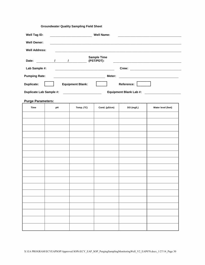
Groundwater Quality Sampling Field Sheet
Well Tag ID:
Well Name:
Well Owner:
Well Address:
Date: / / Sample Time (PST/PDT):
Lab Sample #:
Crew:
Pumping Rate: Meter: Duplicate: Equipment Blank: Reference: Duplicate Lab Sample #: Equipment Blank Lab #: Purge Parameters:
Time pH Temp. (ºC) Cond. (µS/cm) DO (mg/L) Water level (feet)

X:\EA PROGRAM\ECYEAPSOP\Approved SOPs\ECY_EAP_SOP_PurgingSamplingMonitoringWell_V2_EAP078.docx_1/27/14_Page 31
Groundwater Quality Sampling Field Sheet (cont.)
Well Tag ID:
Well Name:
Photometric O2 : Kit: Conc.
Photometric O2 : Kit: Conc.
Colormetric O2 :
Field Alkalinity : Kit: Conc.
ORP:
Other:
Comments :
Purge Parameters (cont.):
Temp (oC) Cond(µS/cm)Time DO (mg/L)pH
X:\EA PROGRAM\ECYEAPSOP\Approved SOPs\ECY_EAP_SOP_PurgingSamplingMonitoringWell_V2_EAP078.docx_1/27/14_Page 32
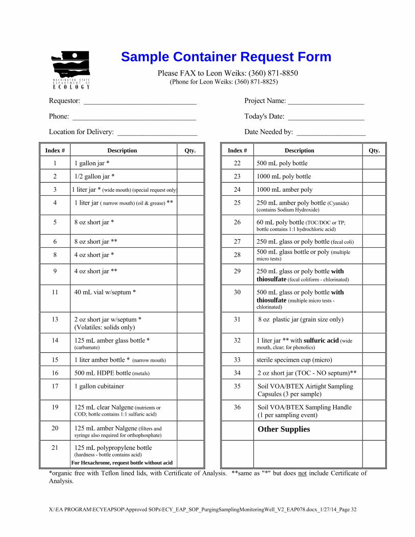
Sample Container Request Form Please FAX to Leon Weiks: (360) 871-8850 (Phone for Leon Weiks: (360) 871-8825)
Requestor: _______________________________ Project Name: _____________________ Phone: __________________________________ Today's Date: _____________________ Location for Delivery: ______________________ Date Needed by: ___________________
Index # Description Qty. Index # Description Qty.
1 1 gallon jar * 22 500 mL poly bottle
2 1/2 gallon jar * 23 1000 mL poly bottle
3 1 liter jar * (wide mouth) (special request only) 24 1000 mL amber poly
4 1 liter jar ( narrow mouth) (oil & grease) ** 25 250 mL amber poly bottle (Cyanide) (contains Sodium Hydroxide)
5 8 oz short jar * 26 60 mL poly bottle (TOC/DOC or TP; bottle contains 1:1 hydrochloric acid)
6 8 oz short jar ** 27 250 mL glass or poly bottle (fecal coli)
8 4 oz short jar * 28 500 mL glass bottle or poly (multiple micro tests)
9 4 oz short jar ** 29 250 mL glass or poly bottle with thiosulfate (fecal coliform - chlorinated)
11 40 mL vial w/septum * 30 500 mL glass or poly bottle with thiosulfate (multiple micro tests - chlorinated)
13 2 oz short jar w/septum * (Volatiles: solids only)
31 8 oz plastic jar (grain size only)
14 125 mL amber glass bottle * (carbamate)
32 1 liter jar ** with sulfuric acid (wide mouth, clear; for phenolics)
15 1 liter amber bottle * (narrow mouth) 33 sterile specimen cup (micro)
16 500 mL HDPE bottle (metals) 34 2 oz short jar (TOC - NO septum)**
17 1 gallon cubitainer 35 Soil VOA/BTEX Airtight Sampling Capsules (3 per sample)
19 125 mL clear Nalgene (nutrients or COD; bottle contains 1:1 sulfuric acid)
36 Soil VOA/BTEX Sampling Handle (1 per sampling event)
20 125 mL amber Nalgene (filters and syringe also required for orthophosphate)
Other Supplies
21 125 mL polypropylene bottle (hardness - bottle contains acid)
For Hexachrome, request bottle without acid
*organic free with Teflon lined lids, with Certificate of Analysis. **same as "*" but does not include Certificate of Analysis.

X:\EA PROGRAM\ECYEAPSOP\Approved SOPs\ECY_EAP_SOP_PurgingSamplingMonitoringWell_V2_EAP078.docx_1/27/14_Page 33
PRE-Sampling Notification Fax to Manchester Laboratory: (360) 871-8850
Project Name: _______________________________________________________ SIC: _________________________
Requested by: _____________________________________________ Sampling Date(s): _________________________
Program: _____________________________________________________ Date to Lab: _________________________
Phone No.: _______________________________________ Sample Pickup Location: _________________________
QAPP: �Yes � No Date results needed by: ____________________
General Chemistry W S O Microbiology W S O Organic Chemistry W S O
Alkalinity Fecal Coliforms � MF � MPN Base/Neutral/Acids (BNA)
Conductivity E. Coli MF � “MUG” � mTEC2 Polynuclear Aromatics (PAH)
Hardness E. Coli MPN
pH % Klebsiella Volatile Organic Analysis (VOA)
Turbidity BTEX
� Fluoride � Chloride � Sulfate Pest/PCB's (Organochlorine)
Cyanide � Total � Dissociable Metals WT WD S O Pesticides only (Organochlorine)
Total Solids Priority Pollutant Metals (13 elements) PCB's only
Total Nonvolatile Solids TCLP metals OP - Pests (Organophosphorous)
Total Suspended Solids Hardness Herbicides (Chlorophenoxy)
Total Nonvolatile Suspended Nitrogen Pesticides
Total Dissolved Solids Mercury (Hg) � Low Level � Regular
PCL Pesticides (8085)
Chlorophyll � Filtered in field � Filtered at lab
Other: List individual elements: PBDEs
% Solids Hydrocarbon ID (match to source)
% Volatile Solids (TVS) TPH-ID (gas/diesel/oil)
Total Organic Carbon TPH-Gx
Dissolved Organic Carbon TPH-Dx
Biochemical Oxygen Demand (BOD) 5 day
BOD - Inhibited TCLP-VOA
BOD - Ultimate TCLP-BNA
Ammonia TCLP-Herbicides
Nitrate-Nitrite TCLP-Pesticides
Orthophosphate
Total Phosphorous
� TPN � TKN Asbestos
Comments: Enter the number of samples in the appropriate box(es) above. W = water S = soil/sediment O = other (please specify) W TR = water total W D = water dissolved
Enforcement
Monitoring
Emergency
Class II
Preliminary Invest.
Special turnaround
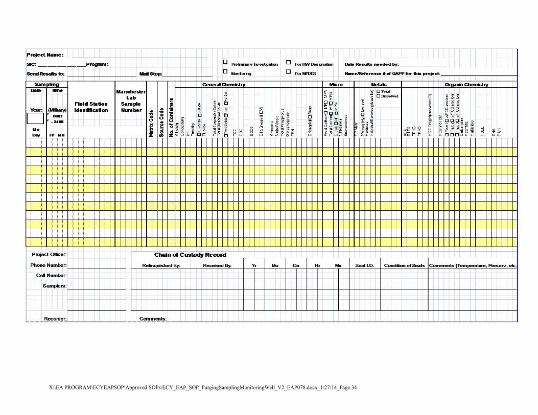
X:\EA PROGRAM\ECYEAPSOP\Approved SOPs\ECY_EAP_SOP_PurgingSamplingMonitoringWell_V2_EAP078.docx_1/27/14_Page 34

X:\EA PROGRAM\ECYEAPSOP\Approved SOPs\ECY_EAP_SOP_PurgingSamplingMonitoringWell_V2_EAP078.docx_1/27/14_Page 35
Matrix Codes Code Description 10 Water 11 Field Filtered Water 12 Filter from Water 13 Water to be filtered upon receipt at lab 40 Soil/Sediment 41 Frozen Soil/Sediment (PSEP) 45 Semi-Solid/Sludge 70 Tissue 80 Oil/Solvent 90 Waste 00 Other (Use only if no other apply)
Source Codes Code Description 00 Unspecified Source 01 Unknown Liquid Media (Drum/Tank) 02 Unknown Liquid Media (Spill Area) 03 Unknown Liquid Media (Waste Pond) 10 Water (General) 12 Ambient Stream/River 13 Lake Reservoir 14 Estuary/Ocean 15 Spring/Seepage 16 Rain 17 Surface Runoff/Pond (general) 18 Irrigation Canal/Return Flow 20 Well (General) 21 Well (Industrial/Agricultural) 22 Well (Drinking Water Supply) 23 Well (Test/Observation) 24 Drinking Water Intake 25 Drinking Water (At Tap) 30 Effluent Wastewater (General) 31 Municipal Effluent 32 Municipal Inplant Waters 33 Industrial Surface Runoff/Leachate 34 Industrial Effluent 35 Industrial Inplant Waters 36 Industrial Surface Runoff/Pond 37 Industrial Waste Pond 38 Landfill Runoff/Pond/Leachate 40 Sediment (General) 42 Bottom Sediment or Deposit 44 Sludge (General) 45 Sludge (WastePond) 46 Sludge (Drum/Tank) 48 Soil (General) 49 Soil (Spill/Contaminated Area)
Code Description 50 Bore Hole Material 60 Air (General) 61 Ambient Air 62 Source or Effluent Air 63 Industrial or Workroom Air 70 Tissue (General) 71 Fish Tissue 72 Shellfish Tissue 73 Bird Tissue 74 Mammal Tissue 75 Macroinvertebrate 76 Algae 77 Periphyton 78 Plant/Vegetation 80 Oil/Solvent (General) 81 Oil (Transformer/Capacitor) 82 Oil/Solvent (Drum Tank) 83 Oil/Solvent (Spill Area) 84 Oil/Solvent (Waste/Pond) 90 Commercial Product Formulation 95 Well Drill Water 96 Well Drill Mud 97 Well Sealing Material 98 Gravel Pack Material

X:\EA PROGRAM\ECYEAPSOP\Approved SOPs\ECY_EAP_SOP_PurgingSamplingMonitoringWell_V2_EAP078.docx_1/27/14_Page 36
Appendix B: Collecting Samples for Volatile Organics and other Organic Compounds
This Appendix applies to EAP staff collecting and handling groundwater samples for volatile organic compounds (VOCs) and other organic compounds (e.g. semi-volatiles, total petroleum hydrocarbons, polynuclear aromatic hydrocarbons, pesticides, polychlorinated biphenyls).
It describes common procedures and practices that EAP staff use to collect these samples from wells without dedicated sampling pumps. General information is provided here and in Section 6.0 of this SOP to help guide field staff in the selection of proper sample equipment and sampling techniques. There are several documents that provide detailed information on this topic, including the USGS National Field Manual for the Collection of Water-Quality Data (USGS, 1997) and The Essential Handbook of Ground-Water Sampling (Nielsen, 2007).
Sample Equipment Selection
Selecting equipment for purging and sampling a well for VOCs, other volatile analytes and organics requires specific considerations, preparations and precautions. All sample-contact components of the equipment used should be constructed of stainless steel or Teflon®. The manner of sample equipment operation must be compatible with characteristics of the well and the analytes being sampled to obtain data that will meet the project objectives and data quality requirements.
When sampling for volatile analytes sample equipment should be chosen to minimize changes in pressure, temperature and atmospheric exposure of the water pulled from the aquifer. For this reason these samples should be collected with positive pressure/displacement pumps. Positive pressure pumps most commonly used by EAP are stainless steel submersible or bladder pumps.
Although peristaltic pumps are regularly used to purge and sample monitoring wells they are not recommended for sampling volatile analytes. Peristaltic pumps are negative pressure or suction lift pumps that create a vacuum in the intake line that draws the sample to the land surface. The vacuum can result in the loss of volatile analytes.
Following are some basic considerations for the most commonly used sample equipment.
Submersible and Bladder Pumps
Submersible and bladder pumps have similar operating requirements. Both are lowered into the well’s water column. The pumps should be slowly lowered through the water column to avoid stirring up particulates or aerating the water in the well casing.
It is recommended that the intake depth of the pump and pumping rate for wells that are sampled repeatedly remain the same for all sample events. Typically the pump intake is placed at the midpoint or the lowest historical midpoint of the saturated screen length. The pump intake depth will be determined by the project manager and should be specified in the QAPP.
X:\EA PROGRAM\ECYEAPSOP\Approved SOPs\ECY_EAP_SOP_PurgingSamplingMonitoringWell_V2_EAP078.docx_1/27/14_Page 37
Both submersible and bladder pump need to be completely submerged to operate properly. Consult with the pump manufacturer to determine the minimum height of the water column above the pump for it to operate properly. This can range from 1 foot to more than 5 feet.
If possible the pump intake should be at least two feet above the bottom of the well, to minimize mobilization and uptake of particulates present in the well bottom.
Ideally, the pumping rate should be set so as not to cause significant drawdown in the well. Wells should be pumped at a rate that is equal to or less than the natural flow conditions of the aquifer in the screened interval to avoid drawing the water level down.
Small diameter bladder pumps are available for sampling small diameter wells which are becoming increasingly common in groundwater investigations.
Careful considerations should be given to placing pumps in wells that are excessively contaminated with free product (LNAPL or DNAPL) because it may be difficult to adequately decontaminate severely contaminated pumps in the field. When wells of this type are encountered, alternative sampling methods should be considered such as a peristaltic pump or bailer.
Peristaltic Pumps
Peristaltic pumps are generally not recommended for sampling volatile analytes because of the potential loss of analytes due to pump operation.
If a peristaltic pump is being considered to sample volatile analytes, the intended use of the data should be a primary consideration.
• Use of the pump may be acceptable if the additional sample error that may be introduced by the negative pressure/vacuum created by the pumps operation does not affect any project decision making. For example, if contaminant concentrations are far above regulatory levels and groundwater monitoring will continue, then a peristaltic pump could be used. However, the data should only be used to qualitatively evaluate the presence of the contaminants.
• A peristaltic pump should not be used if minor differences in the groundwater concentrations of volatile analytes could affect project decisions. For example, do not use a peristaltic pump when monitoring groundwater remediation to determine if cleanup goals have been achieved. In these cases sample equipment should be selected that will provide more accurate results.
Peristaltic pumps may be used to sample if the physical characteristics of the well limits other sample equipment options, such as when sampling smaller diameter wells. Small diameter tubing used with a peristaltic pump is a possible option. However, the tubing used in the rotor head of the peristaltic pump should be less than a foot in length since it is found to be more gas permeable and sorptive of organic compounds. This tubing should be replaced at each sample location. PharMed tubing is now recommend for use in the pump rotor head since it has been found to be less permeable to gas and vapors as compared to other soft tubing options.

X:\EA PROGRAM\ECYEAPSOP\Approved SOPs\ECY_EAP_SOP_PurgingSamplingMonitoringWell_V2_EAP078.docx_1/27/14_Page 38
Peristaltic pumps may also be used in low yielding wells that do not have sufficient water to operate a submersible pump.
Bailers
Even though bailers are not recommended for most groundwater sampling, they are useful in specific situations.
The use of bailers is discouraged because the repeated entry and removal of the bailer disturbs the water column and may mobilize sediment that is present in the well. The repeated disturbance to the water column can also aerate the water in the well casing.
However, in wells that are excessively contaminated with oily compounds, bailers can be an acceptable alternative to pumps. Bailers are easier to clean or can be disposable.
If a bailer is used to sample for volatile organic compounds, it should be a closed-top Teflon® bailer with a bottom-emptying sample device. The bailer should be lowered and raised smoothly at a constant rate and with as little disturbance to the water column as possible.
Passive Samplers
Although EAP does not have direct experience with passive samplers the devices are an emerging technology for evaluating volatile organics and other analytes in groundwater.
Passive samplers are no-purge sampling devices designed to collect samples from a specific depth within a well that is in ambient equilibrium with the adjacent groundwater. There are a variety of passive samplers, these include: devices that rely on sorption or diffusion onto or across the sampler medium to devices that recover grab samples at discrete depths.
If considering a passive sampling device for your project, consult with the manufacturer to determine if the technology is compatible with the project goals and site conditions.
Sampling Considerations for Volatile Analytes
The following are general considerations when collecting samples for volatile analytes. Please refer to Section 6.0 of this SOP for instructions on basic monitoring well sampling procedures (e.g. water level measurement, well purging).
• Whenever possible, wells should be sampled in order of increasing chemical concentrations (known or anticipated). This minimizes the possibility for cross-contamination of sample equipment.
• Protect the sample area from potential sources of airborne contaminants (e.g. dust, vapors from fuel cans, engine exhaust, etc.). Record on the field data sheets suspected but unavoidable extraneous VOC sources that are encountered when sampling.
• While in the field try to keep unfilled sample bottles in a cool place (e.g. shade, ice-filled cooler). This will minimize the loss of volatile analytes when filling the sample bottles.

X:\EA PROGRAM\ECYEAPSOP\Approved SOPs\ECY_EAP_SOP_PurgingSamplingMonitoringWell_V2_EAP078.docx_1/27/14_Page 39
• If collecting samples for multiple analytes, VOC samples (and other sensitive analytes) are typically collected first since these analytes are most sensitive to the sampling process.At low purge rates direct sun light and hot ambient air temperatures may cause groundwater in the tubing and flow cell to heat up. This may cause the groundwater to degas which will result in loss of volatile analytes. If possible shade the equipment from sunlight.
Sampling Procedures
Although the procedures used to fill sample bottles may seem a minor consideration, filling them improperly can jeopardize the careful work that went into properly purging a well to produce minimally-disturbed, representative samples. Improper sampling techniques can cause changes in sample composition due to agitation and exposure to air which can result in the loss of contaminants by volatilization or degassing.
The more sensitive the parameter being collected (e.g. VOCs and redox-sensitive metals), the more cautious and rigorous the filling procedures should be.
Filling VOC bottles
• Groundwater samples for VOC analysis are collected in 40-mL amber/clear glass bottles with Teflon® septa lids. Contact the laboratory to determine the number of bottles required for analysis.
• Samples may be collected after the well is fully purged. Purging and sample withdrawal should form a continuous process.
• Pumping rates for sample collection should be high enough to fill sample bottles efficiently and with minimal exposure to atmospheric conditions, but low enough to minimize sample alteration or aeration. The flow should be smooth and uniform.
o The recommend pumping rate for collecting VOC samples is generally 250 mL/min or less.
o If using a bladder pump, the pumping rate should be set to deliver a pulse of water long enough to fill one 40-mL VOC bottle.
• Before filling the sample bottles check for air bubbles in the sample line. Tap the sample line or gradually adjust the pumping rate to dislodge and remove any bubbles that are present.
• Wear clean disposable powder free gloves when collecting and preserving the samples.
• Keep sample bottles capped until it’s time to fill them. This will minimize exposure of the sample bottle to extraneous VOC contamination.
• Do not pre-rinse or field rinse VOC bottles before sample collection.
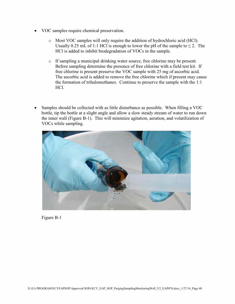
X:\EA PROGRAM\ECYEAPSOP\Approved SOPs\ECY_EAP_SOP_PurgingSamplingMonitoringWell_V2_EAP078.docx_1/27/14_Page 40
• VOC samples require chemical preservation.
o Most VOC samples will only require the addition of hydrochloric acid (HCl). Usually 0.25 mL of 1:1 HCl is enough to lower the pH of the sample to ≤ 2. The HCl is added to inhibit biodegradation of VOCs in the sample.
o If sampling a municipal drinking water source, free chlorine may be present. Before sampling determine the presence of free chlorine with a field test kit. If free chlorine is present preserve the VOC sample with 25 mg of ascorbic acid. The ascorbic acid is added to remove the free chlorine which if present may cause the formation of trihalomethanes. Continue to preserve the sample with the 1:1 HCl.
• Samples should be collected with as little disturbance as possible. When filling a VOC bottle, tip the bottle at a slight angle and allow a slow steady stream of water to run down the inner wall (Figure B-1). This will minimize agitation, aeration, and volatilization of VOCs while sampling.
Figure B-1

X:\EA PROGRAM\ECYEAPSOP\Approved SOPs\ECY_EAP_SOP_PurgingSamplingMonitoringWell_V2_EAP078.docx_1/27/14_Page 41
• Carefully fill the bottle to just below the rim (Figure B-2).
Figure B-2
• If the sample bottle was not pre-preserved, add the preservative.
• Fill the cap with water and use it to top off the sample (Figure B-3).
Figure B-3

X:\EA PROGRAM\ECYEAPSOP\Approved SOPs\ECY_EAP_SOP_PurgingSamplingMonitoringWell_V2_EAP078.docx_1/27/14_Page 42
• Add just enough water to form a positive meniscus (Figure B-4). Take care to not over fill the bottle since you do not want to flush any preservative out of the bottle while topping it off.
Figure B-4
• Empty the cap of any remaining water before replacing it on the bottle.
• After securing the cap invert the bottle and tap it lightly to check for bubbles (Figure B-5 and B-6). Absolutely no bubbles or headspace should be present in the bottle. If any airspace remains, VOCs in the sample can volatilize and may be lost before analysis.
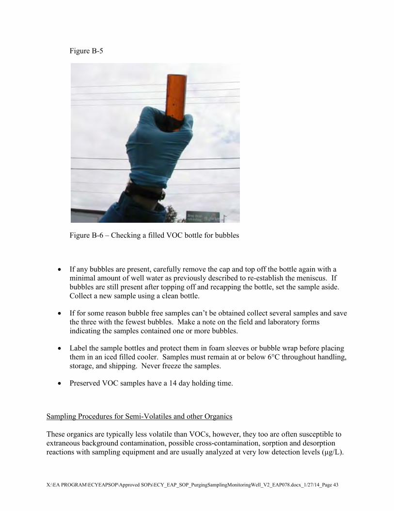
X:\EA PROGRAM\ECYEAPSOP\Approved SOPs\ECY_EAP_SOP_PurgingSamplingMonitoringWell_V2_EAP078.docx_1/27/14_Page 43
Figure B-5
Figure B-6 – Checking a filled VOC bottle for bubbles
• If any bubbles are present, carefully remove the cap and top off the bottle again with a minimal amount of well water as previously described to re-establish the meniscus. If bubbles are still present after topping off and recapping the bottle, set the sample aside. Collect a new sample using a clean bottle.
• If for some reason bubble free samples can’t be obtained collect several samples and save the three with the fewest bubbles. Make a note on the field and laboratory forms indicating the samples contained one or more bubbles.
• Label the sample bottles and protect them in foam sleeves or bubble wrap before placing them in an iced filled cooler. Samples must remain at or below 6°C throughout handling, storage, and shipping. Never freeze the samples.
• Preserved VOC samples have a 14 day holding time.
Sampling Procedures for Semi-Volatiles and other Organics These organics are typically less volatile than VOCs, however, they too are often susceptible to extraneous background contamination, possible cross-contamination, sorption and desorption reactions with sampling equipment and are usually analyzed at very low detection levels (μg/L).

X:\EA PROGRAM\ECYEAPSOP\Approved SOPs\ECY_EAP_SOP_PurgingSamplingMonitoringWell_V2_EAP078.docx_1/27/14_Page 44
Some substances that fall under this category include: base/neutral/acids (BNAs or semi-volatiles), total petroleum hydrocarbons (TPH), polynuclear aromatic hydrocarbons (PAHs), herbicides, pesticides, polychlorinated biphenyls (PCBs), and polybromide diphenyl ether congeners (PBDEs). The following table lists sample containers, preservation, and holding times for commonly sampled organics.
Table 1. Sample Containers, Preservation and Holding Times
Parameter Matrix Minimum Quantity Required
Container Preservative Holding Time
VOCs Groundwater 40 mL, no headspace
(3) 40 mL vials with septum
HCl. Ascorbic acid when chlorinated.
Cool to ≤6°C. No headspace.
14 days
BNA (Semi-VOCs) Groundwater 1 L 1 L amber glass
bottle Cool to ≤6°C 7 days
TPH-D Groundwater 1 L 1 L narrow mouth glass bottle
Cool to ≤6°C
7 days unpreserved;
14 days preserved
PAH Groundwater 1 L 1 L amber glass bottle
Cool to ≤6°C 7 days
Herbicides Groundwater 1 L 1 L amber glass bottle
Cool to ≤6°C 7 days
Pesticides Groundwater 1 to 4 L 1 L amber glass bottle
Cool to ≤6°C 7 days
PCBs Groundwater 1 to 4 L 1 L amber glass bottle
Cool to ≤6°C 7 days
PBDEs Groundwater 1 L 1 L amber glass bottle
Cool to ≤6°C 7 days
Sampling procedures for semi-volatiles and other organics are similar to those for VOCs.
• Equipment should be made of inert material to the extent possible.
• Samples may be collected once the well is fully purged.
• The pumping rate for larger sample containers is generally 0.5 L/min or less.
• Before filling sample bottles check for air bubbles in the sample line. Tap the sample line or gradually adjust the pumping rate to dislodge and remove any bubbles that are present.
• Collect samples in the order specified in the project QAPP.

X:\EA PROGRAM\ECYEAPSOP\Approved SOPs\ECY_EAP_SOP_PurgingSamplingMonitoringWell_V2_EAP078.docx_1/27/14_Page 45
• Do not pre-rinse or field rinse sample bottles for organic analysis.
• When filling a sample container tip it at a slight angle and allow a slow steady stream of water to run down the inner wall. This will minimize agitation and aeration while filling the container.
• Fill the bottle to the recommend volume. If the sample will be frozen, leave enough head-space to prevent the bottle from breaking due to ice expansion.
• These samples are not usually preserved or filtered; however, they should be cooled to 6oC or less immediately after collection.