w.a. kilgore, s. balakrishna, c.w. bobbitt and p
TRANSCRIPT

AIAA-2003-0754Recent Enhancements to the National
Transonic Facility (Invited)
W.A. Kilgore, S. Balakrishna, C.W.NASA Langley Research CenterHampton, Virginia
Bobbitt and P. Underwood
41st AIAA Aerospace Sciences Meeting & Exhibit6-9 January 2003
Reno, Nevada
For permission to copy or republish, contact the copyright owner named on the first page. For AIAA-heldcopyright, write to AIAA Permissions Department,
1801 Alexander Bell Drive, Suite 500, Reston, VA 20191-4344.


AIAA-2003-0754
RECENT ENHANCEMENTS TO THE NATIONAL TRANSONICFACILITY
W. A. Kilgore*, S. Balakrishna t, C. W. Bobbitt _ and P. Underwood §
Aerodynamics, Aerothermodynamics, and Acoustics CompetencyNASA Langley Research Center
Hampton, Virginia
ABSTRACT
The National Transonic Facility continues to makeenhancements to provide quality data in a safe,efficient and cost effective method for
aerodynamic ground testing. Recentenhancements discussed in this paper include the
restoration of reliability and improved performanceof the heat exchanger systems resulting in the
expansion of the NTF air operations envelope.
Additionally, results are presented from acontinued effort to reduce model dynamics
through the use of a new stiffer balance and sting.
INTRODUCTION
The National Transonic Facility (NTF) located at
the NASA Langley Research Center is a closedcircuit continuous flow wind tunnel used to obtain
aerodynamic data at subsonic and transonic
speeds up through full-scale Reynolds numbersfor most flight vehicles. The NTF can operate as aconventional pressure wind tunnel using dry air as
the test medium and a cooling coil for temperaturecontrol or as a cryogenic pressure tunnel using
nitrogen as the test medium and evaporating liquidnitrogen into the flow to control temperature.
The NTF test section is a square filleted cross-
section (approximately 8.2 feet per side) that canbe configured either with slotted-walls (6% openratio) or solid walls. It can operate at Mach
numbers from 0.1 up to 1.2 (1.1 in air), Reynoldsnumbers up to 146 million per foot, total
temperatures from 140°F down to -260°F, and
total pressures from atmospheric up to 130 psia.The NTF has a t01MW fan drive system that
provides the necessary power to ddve the test gas
*Facility Manager - National Transonic Facility, NASA-LaRC,Senior Member, AIAA
1"SeniorResearch Scientist, ViGYAN Inc.
tResearch Engineer, NASA-I_aRC
§Test Engineer, ViGYAN Inc., Member, AIAA
This materialis declared a workof the U. S. Government and isnot subjectto copyrightprotectioninthe United States.
around the circuit with dynamic pressures up to
7000 psf. Figures 1 and 2 show the standardoperational envelopes for cryogenic nitrogen
operations at -250°F and air operations at 120°F,
respectively. Both sting-mounted full-span modelsand wall-mounted semi-span models can be
tested in the facility.
NTF AIR OPERATIONS IMPROVEMENTS
For air operations, the NTF operates as aconventional tunnel with the added benefits of the
ability to pressurize and the ability to maintaintemperature. Operating the NTF in air mode
provides a cost effective method of testing whilestill achieving higher Reynolds number testing
than many other ground-based test facilities.
The air operations envelope is shown in figure 2.The NTF cannot run below atmospheric pressures
(PT -> 14.7 psia) and therefore the air envelope hasa minimum Reynolds number limit for all Mach
numbers. For low-speed testing (M < 0.5), the
maximum Reynolds number is limited by themaximum allowed tunnel total pressure (PT = 130
psia). For supersonic testing, the limit is a Mach
number of 1.1 set by the test-section geometry.For transonic testing, the maximum Reynolds
number is limited by the capacity of the coolingcoil to remove sufficient heat to hold the free
stream total temperature constant.
As its name suggests, the National TransonicFacility spends much of its time operating in thetransonic regime. Therefore, the limitation
imposed by the capacity of the cooling coil is ofgreat importance to the facility. Degradation of thissystem over time has reduced its capacity and
therefore, further limited the transonic air
operations envelope. An additional problem withthe cooling coil has been leaks, which have
introduced moisture into the tunnel, requiringincreased expense to dry the tunnel. Furthermore,at times this moisture in the tunnel has
compromised test data by forming frost on the testarticle.
1American Institute of Aeronautics and Astronautics

AIAA-2003-0754
To combat these problems while still maintaining
the NTF's cost effective air operations, work wasrecently performed to restore the integrity of this
cooling coil and to increase the capacity of the
cooling system thereby expanding the transonicair operations envelope. Details of this work, aswell as the results and future plans, are describedbelow.
Coolina System Backqround
The purpose of the NTF cooling system is tobalance the heat entering and exiting the tunnel
circuit such that the desired testing temperature is
stable. The majority of the heat introduced into thetunnel circuit is through the fan drive system (witha maximum power of 101MW). For tunnel
operations using nitrogen as the test medium,liquid nitrogen is evaporated into the tunnel circuitbetween the diffuser and fan to achieve the
desired stable temperature. For air operations, thecenterpiece of the cooling system is the coolingcoil, which is a cross-flow type heat exchanger
located in the settling chamber of the tunnel.
Figure 3 represents this type of cross flow heat
exchanger where the cooling water flows throughthe cooling coil tubes and removes heat from thedry air cross flow.
Cross-flow heat exchangers operate according tothe following heat transfer rate equation:
q=UAF_T_where
q = heat transfer rate
(1)
U = overall heat transfer rate coefficient
A = effective surface area for heat exchange
F = correction factor for cross-flow heat
exchanger (function of heat exchangerdesign and inlet and exit temperatures
of the two fluids, range 1.0 for idealdown to 0.5)
Amlm ---- (_T2 - AT1 ) / In (_T2 / _T1 )= logarithmic mean temperature
difference
_T1 = Tair,in - Twater,out
AT2 -- Tair.ou t - Twater.in
Based on this equation the heat transfer rate, q,(from the point of view of the heat exchanger
system) is controlled by the cooling coil design,size, physical condition, and the inlet and exit flow
temperatures of the cooling water and dry air.
Figure 4 shows a piping schematic of the NTF
cooling system. The cooling coil, located in the
tunnel settling chamber, consists of two layers(upstream and downstream) of 781 finned (8fins/inch) elliptical copper tubes (inside dimensions
of 1.3 inches x 0.43 inches) arranged in four
staggered rows that extend across the settlingchamber (Figure 5). Each layer has 18 bundles ofwhich 6 bundles are 36 inches wide and 12
bundles are 18 inches wide with the lengths
ranging from 20 to 36 feet. The upstream layer
has water flowing from the bottom to the top, andthe downstream layer has water flowing from thetop to the bottom. The total effective surface area,
A, for the cooling coil is approximately 105,500 _2
The water supplied to the cooling coil inlet comes
from a 78,000 gallon cooling tower water sump.This supply water is pumped via two large waterpumps to the cooling coil through a long supply
pipe (341 feet of 16 inch diameter carbon steelpipe followed by 120 feet of 10 inch stainless steelpipe) at a constant flow rate of about 8600 gallons
per minute (gpm). At the end of the supply pipethe water is distributed into a 10 inch diameter
manifold that feeds 36 smaller pipes (2 inch, 3inch and 4 inch) leading to each bundle. As the
water passes through the cooling coil it increasesin temperature as it absorbs the heat of the tunnelcircuit flow. The warm return water is then
returned to the cooling tower through 36 smallerpipes into a 10 inch diameter manifold and then
enters the long ratum pipe (137 feet of 10 inch
stainless steel pipe followed by 299 feet of 16 inchdiameter carbon steel pipe). Prior to reaching the
cooling tower the water passes through a bypassvalve where it is either passed back into the watersupply pipe or continues on and is dropped into
the top of the cooling tower. The amount of waterthrough the bypass valve is based on the desiredtunnel total temperature. As the return water is
dropped into the top of the cooling tower it passesthrough spray nozzles and mixing screens to cool
the water. Additional cooling is provided by threeforced draught fans located at the top of the
cooling tower that mix atmospheric air through thetower for atomized spray cooling of the water
thereby exchanging heat with the ambient air.Ideally, with this method the water can be cooledto the atmospheric dew point temperature. The
2
American Institute of Aeronautics and Astronautics

AIAA-2003-0754
thermal capacity of the cooling tower is thereforedictated by the difference between outlet water
temperature and ambient atmospheric dew point.
Assuming an average summer day in Hampton,Virginia, the ideal capacity of the tower is about50MW with a seasonal variation of +3MW.
For a given tunnel condition, the outlet water
temperature from the cooling coil is affected by the
inlet temperature and the mass flow of waterthrough the system. As the mass flow increases,
the outlet temperature decreases but the heattransfer rate and efficiency of the heat exchangerincreases. Therefore, for a given heat exchanger
geometry and minimum inlet water temperatureavailable (set by the cooling tower), an increase inmass flow is the only way to increase the capacity
of heat removal of the cooling coil. Currently, the
thought is to increase the mass flow rate of thesystem to increase the capacity of the cooling
system (thereby increasing the transonic air testenvelope), which will be discussed later.
An additional aspect of the NTF cooling system forair operations is the fact that the cooling coil mustbe drained and dried prior to the commencement
of cryogenic operations. This process is necessaryto prevent any water from remaining in the tubes,which could freeze, expand, and burst the tubing.
Operation and DeteriorationAfter several years of operation, there wereindications that the capacity and integrity of the
NTF cooling system was degrading. Oneindication was the reduction in heat transfer rate
from the designed 34MW limit in 1984 down to27MW in 1999. The second was the increased
number of incidents of cooling coil tube ruptures
during the _:,ycling between warm and cryogenicoperations.
Both of these symptoms pointed toward therestriction of flow through the cooling coil tubes,and if some tubes were completely blocked, theeffective surface area for heat transfer would be
reduced. From the equation for heat transfer ratefor this cross-flow heat exchanger (Equation 1), it
can be seen that either of these situations would
result in a reduction of heat transfer capability.Rupturing of tubes is an indication that water is still
trapped in the tubes after the cooling coil drainingand drying processes are complete. This trappedwater then freezes, expands, and ruptures the
tube. An example of a rupture is shown in figure 6.The only way this water could be trapped in the
tubes is if some debris were present to prevent it
from being removed.
While the reduction of the heat transfer capability
was troubling, the rupturing of the tubes was
devastating. While procedures existed fordetecting leaks prior to the refilling of the cooling
coil after cryogenic operations, it was still possiblefor some small leaks to escape notice, or for
weakened tubes to rupture after the cooling coilhad been refilled. As a result, water would be
introduced into the tunnel. If even small amounts
of this water remained in the tunnel during
cryogenic operations, it would be possible for frost
to form on the test article (shown in figure 7) thatcould compromise the aerodynamic data quality.
More and more time and money were being spent
to dry the tunnel, to recover from ruptures and tominimize the potential for frost until eventually the
decision was made to remove the cooling coil fromservice. It was felt that the major contribution ofthe NTF was high Reynolds number cryogenic
testing, and that this capability should not becompromised by risks associated with airoperations. Therefore, in October 2001 the NTF
cooling coil was removed from service and airoperations were stopped.
Evaluation/Repair/Return to Air OperationsWhile it was and is true that the major contributionof the NTF is the high Reynolds number data it
provides, it soon became clear that the operationof the NTF as a conventional pressurized airtunnel was itself a valuable asset. Therefore, a
team was formed to evaluate, repair, and return
the cooling coil to reliable operational status.
The team's first job was to determine the causes
of the problems and the extent of these problems.Figure 8 shows the relative blockage of each
cooling coil bundle as determined by highpressure air purges of the system. It can be seenthat many of the bundles, indicated by the darker
colors, (particularly bundle 9) had restricted flow.Analysis of the cooling system revealed that themain contributor to the blockage was rust coming
from the carbon steel piping in the system.
Once these blocked bundles were identified, the
clogged or leaking tubes were either repaired orreplaced. After this repair, internal and externalpneumatic pressure leak checks were performed
on the system. When leaks were found, they were
repaired and rechecked until it was clear that allleaks were eliminated. Then leak checks were
3
American Institute of Aeronautics and Astronautics

AIAA-2003-0754
performed using pressurized argon gas (fordetecting small leaks) and internal vacuum checks
to completely verify the cooling coil integrity. Aftersuccessfully completing these leak checks the
system was flushed with high pressure air and
then with water to remove any remaining debris.After this, a hydrostatic test was performed toensure the cooling coil integrity.
Beyond this effort of repair, it was also desired to
prevent this situation from reoccurring, and to give
early warning if a problem did develop. To address
these issues, the team instituted several changes.To prevent further contamination of the cooling
coil, some of the deteriorated carbon steel pipingwas replaced with stainless and a strainer was
installed on the water supply side to prevent large
debris from reaching the cooling coil. Figure 9shows some of the debris captured by the strainer.For detection of problems additional moisture
monitoring instrumentation was installed in the
tunnel circuit to indicate a possible leak in thecooling coil.
Furthermore, procedures and processes were
modified to minimize the possibility of futuremoisture contamination to the tunnel circuit. The
modifications to the process of drying the coolingcoil prior to cryogenic operations now includes the
use of a vacuum pump attached to the coolingcoil. The purpose of the vacuum pump is to lowerthe pressure inside the cooling coil to 0.2 psia to
"boil off" any remaining water (boiling point is
~70°F at 0.2 psia). To accelerate this process thetunnel is heated to above 100°F. The vacuum
pump also provides an additional leak check of thecooling coil prior to refilling it with water.
ResultsThe results from this effort can be seen in two
ways. First, since re-entry into operation (October
2001), the cooling coil has not experienced any
incidents of leaks. Second, the cooling coil repairhas restored the cooling capacity of the system.Figure 10 is a plot of the log mean temperature
difference, ATim (see equation 1), versus tunnel
fan power and shows graphically the increase incooling coil performance from before to after the
repairs. From the equation for the heat exchange
rate, it can be seen that for a given _TIm the fan
power removed has increased. This change canbe attributed to an increase in efficiency (seen in
an increase in the correction factor F), and/or to a
decrease in the thermal resistance (increase in U)and a restoration in the effective cooling area ofthe coil (increase in A). Changes to all of these
parameters would be expected from cleaning the
cooling coil and repairing/replacing sections ofblocked tubes. Figure 10 shows the new maximumcapacity of the cooling system to be near 45MW,
while as stated earlier the design capacity of the
system was only 34MW. This difference can be
attributed to the fact that the cooling system iscapable of lower inlet water temperatures and
higher outlet water temperatures than were
actually assumed in the original design.
Hiqh Power Conditions
The repairs to the cooling coil restored the integrityof the system and increased in the capacity to
approximately 45MW. The current Reynoldsnumber limits of the transonic air operationsenvelope available for NTF were recently
operationally confirmed. For this test, a Machnumber was set, and the tunnel pressure
increased until the maximum Reynolds number
was reached where the cooling system could stillmaintain a constant temperature. This processwas repeated for a range of Mach numbers. Theresults of this test are shown in Table 1. It should
be noted that this test was run in February 2002
and a constant tunnel temperature of 130°F wasallowed, both of which result in some increase in
the cooling capacity of the system beyond 45MW.
Table 1 - Sustained 0 )erations Conditions
M PT TT AT Pma_ Refit
(psia) (°F) (OF) (MW) (millions)0.700 61.00 126.6 +0.2 48.0 13.27
0.840 42.01 126.9 +0.3 49.3 10.87
0.870 37.03 130.0 +0.3 46.3 9.660.910 35.95 130.0 +0.7 48.4 9.55
Test programs at the NTF have already exploitedthis expanded test envelope. Figure 11 shows theadditional test conditions obtained in air for two
test programs that were run both before and after
the improvements to the NTF cooling system.
It is desired to increase the heat removal capacityof the cooling coil to further extend the transonic
air operations envelope. An approach to
increasing the operational envelope is "pulse"
testing. For this method of testing, the coolingcapacity is exceeded briefly (about 10 minutes)while data is being obtained at a desired condition.Since the cooling capacity is exceeded, the
temperature is always climbing; however, thischange in temperature does not exceedacceptable tolerance limits for the short duration of
4American Institute of Aeronautics and Astronautics
AIAA-2003-0754
the run. Table 2 shows the results of one pulse
test where an alpha sweep was run at M=0.84 with
a fan power of almost 60MW. For this alpha
sweep, the temperature only varied a total of 3°F.
Table 2 - Pulse O )erations Conditions
M PT TT AT Pmax Refit
(psia) (°F) (°F) (MW) (millions)0.840 51.98 133.1 +1.4 59.2 13.27
As stated earlier, another method of further
extending this test envelope is to increase themass flow of cooling water through the cooling
coil. Figure 10 shows the experimental verificationof this for the NTF system by comparing a 5600
gpm flow rate (one pump operating, Pump 3 -see
figure 10) versus 8600 gpm (both pumpsoperating, Pumps 3 & 4).
The mass flow for the NTF system could beincreased either by increasing the pump pressureor by reducing losses in the system. Losses in the
system could be reduced by straightening andshortening pipe lengths and/or increasing pipediameters. The cooling coil team study shows that
the total length of the 16 inch diameter carbon
steel piping (640 feet) could be reduced by about150 feet, and many bends and elbows could be
removed. Additionally, the study shows that the16 inch carbon steel pipe continues to deteriorate
posing serious danger to the future of the cooling
system and must be replaced. This piping changewould result in an estimated increase in mass flowrate of about 700 gpm (from 8600 to 9300). 3 Work
is currently underway to replace this last section ofcarbon steel pipe.
Using the analysis for a cross-flow heat exchanger
presented in figure 10 it is possible to predict thenew cooling coil capacity with 9300 gpm water
flow. Two gradients can be defined underequilibrium conditions that characterize the cooling
coil. The first is fan powed/_TIrn, which is about 1.1MW/°F. The second is based on the maximum
recorded ATomof 42.5°F at a flow rate of 8600
gpm. This provides a second characteristic of 202
gpm/°F. As shown in figure 10 the 9300 gpm willincrease to the ATomfrom 42.5 to 46°F
corresponding to new maximum of 51MW.
Based on the cooling tower it appears that 50MWis the practical limit for the current systems since
increases beyond this would require a change to
the cooling tower, as its average capacity is50MW.
DYNAMICS
Throughout the history of high Reynolds number
testing at the NTF several test programs wereseverely limited or cut short because of dynamics.These test limitations manifest themselves as
excessive balance dynamic loads, modeldisplacements and increased data scatter. An
extensive effort was undertaken at the facility that
provided significant reductions of the tunnelstructural dynamics and a small reduction in modeldynamics. 4 Despite these reductions the
limitations still exist as testing programs continueto desire higher loads and higher angles of attack.In an effort to overcome these limitations a new
balance (NTF-116A) and new upper swept stingwere developed to obtain higher loads and provideincreased stiffness as compared with the NTF-113
series balance and upper swept sting combinationpreviously used. 5
113 BalancesThe 113 balances are the workhorse balances at
the NTF and have provided years of reliability and
quality data. The 113 balance, shown in the top offigure 12, is made of a single piece of highstrength maraging steel and has a cylindrical crosssection that is 2.375 inches in diameter and
15.565 inches long. The metric end has a
precision ground cylinder that is secured to the
model with an interference fit dowel pin. The non-metric end has a precision ground cylindrical taperfit with a key and set screw flats for securing to the
sting.
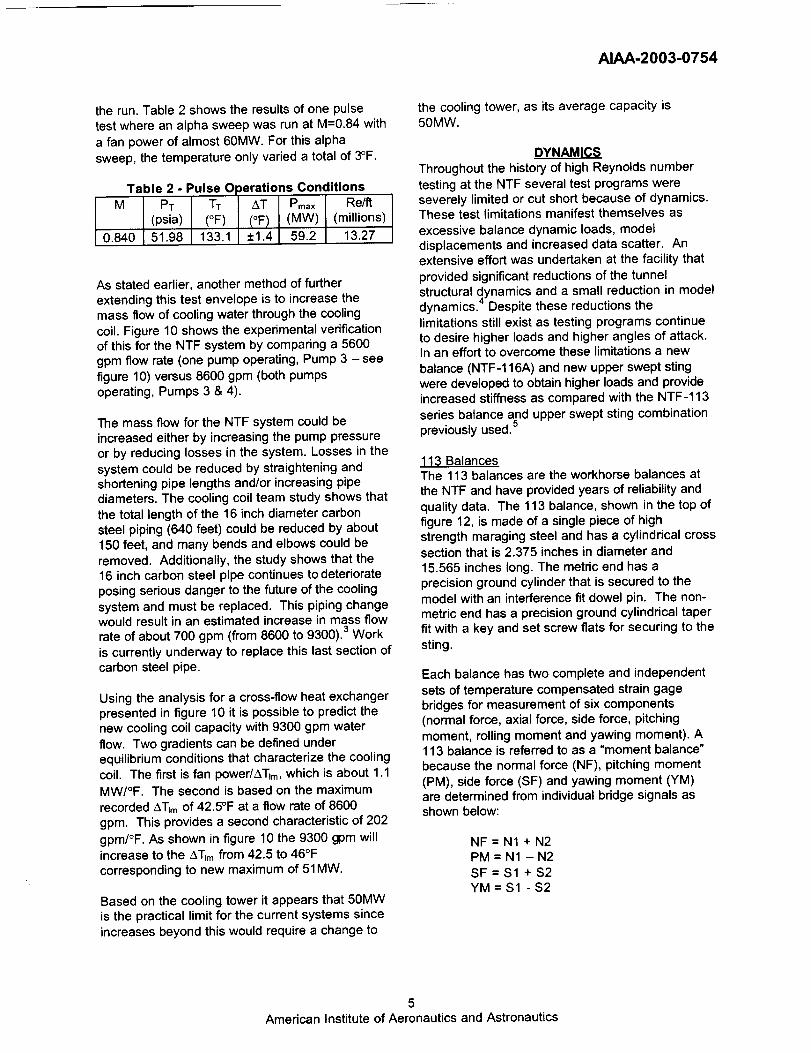
Each balance has two complete and independent
sets of temperature compensated strain gagebridges for measurement of six components(normal force, axial force, side force, pitching
moment, rolling moment and yawing moment). A113 balance is referred to as a "moment balance"
because the normal force (NF), pitching moment
(PM), side force (SF) and yawing moment (YM)
are determined from individual bridge signals asshown below:
NF = N1 + N2PM = N1 - N2
SF = $1 + $2YM = $1 - $2
5
American Institute of Aeronautics and Astronautics

AIAA-2003-0754
116A Balance
In the development of the 116A several changesfrom the 113 balances were incorporated toachieve higher loads and increased stiffness. Likethe 113 the 116A balance, shown in the bottom of
figure 12, is made from a single piece of high
strength maraging steel. The 116A has a largercross section and is a non-symmetric octagonal
shape 3.6 inches high and 4.0 inches wide. Thelarger octagonal shape provides greater loadcapability, and having the width greater than the
height provides higher yaw directional stiffness.
Again to increase stiffness, the length of 116A wasreduced from the 113 by about two inches to13.75 inches.
The 116A mechanical connections on both ends of
the balance are flanges with through boltconnections. These flanges provide stiffermechanical connections and have shorter
interfaces allowing room for simple adaptors toprovide proper placement of the balance within amodel.
The 116A like the 113 has two complete andindependent sets of temperature compensated
strain gage bridges for measurement of sixcomponents. The 116A is referred to as a "forcebalance" because all forces and moments are
direct outputs from the bridges. This configurationallows for an increase in the sensitivity of thestrain measurement.
A direct comparison of the size, load capabilityand the accuracy of these two balances are
presented in Tables 3, 4 and 5.
Tabh 3 - Balance ComparisonNTF-113 NTF-116A
Material Vascomax Vascomax2OO 200
cylindricalShapeDiameter
LengthMounting,Metric
Mounting,Non-Metric
Type
2.375 in
15.575 in 13.75 in
cylinder w/
dowel pincylindricaltaper with
keymoment
octagonal3.6 in x 4.0 in
flange w/
through boltsfiangew/
through bolts
force
Table 4 -
Component
Normal
Force (Ib)Axial Force
(Ib)Side Force
(Ib)PitchingMoment
(in-lb)RollingMoment
(in-lb)
YawingMoment
(in-lb)
Balance Load CapacityNTF-113B NTF-116A
Full Scale Full Scale
±6,520 ±10,000
±400 ±700
±4,000 ±4,0O0
±12,800 ±40,000
±8,150 ±16,000
_+6,400 +_24,000
Table 5 - Balance Accuracy113B ;I16A
Component Accuracy Accuracy
Normal
Force
(Ib)Axial Force
(Ib)Side Force
(Ib)
PitchingMoment
(in-lb)RollingMoment
(in-lb)YawingMoment
(in-lb)
95% Conf.
(% of F. S.)
0.05%
(3.26 Ib)
0.24%
(0.96 tb)0.13%
(5.2 Ib)
0.09%
(11.5 in-lb)
95% Conf.
(% of F. S.)
0.07%
(7 Ib)
0.38%
(2.66 Ib)0.05%
(2 Ib)
0.11%
(44 in-lb)
0.21% 0.2%
(17.1 in-lb) (32 in-lb)
0.16% 0.05%
(10.3 in-lb) (12 in-lb)
The 116A clearly provides a significant increase in
the load capability over the 113 balances whilemaintaining acceptable accuracy.
New Sting
The new flange style mountings of 116A requireda new sting, so the opportunity to add stiffness to
the new sting design was undertaken. The
requirements for this new upper swept sting wereto attach to the 116A balance, conform to
aerodynamic requirements, and provide additionalstiffness in an attempt to further reduce model
6
American Institute of Aeronautics and Astronautics

AIAA-2003-0754
dynamics. Figure 13 shows this new sting with thebalance interface flange exposed.
To match the 116A balance capacity the new stingdesign required an increased stiffness for the
normal force direction and pitching moment.Slight increases to the width and length of thevertical blade section and an increase in the
diameter of the aft end (where it connects to the
tunnel stub sting) accomplished this. Significantdimensional changes could not be made with out
compromising the aerodynamic quality of the
sting.
A series of balance/sting deflection tests weremade to experimentally determine the increasedstiffness of the new balance/sting combination.
Table 6 shows the comparison of the measuredbalance/sting deflection coefficients for the
113B/sting and the new 116A balance with the
new sting.
Table 6 Balance/Sting Stiffness
StiffnessCoefficient
KNF (deg/Ib)KpM (deg/Ib)
113B and
Upper Sting
3.1x10-"6.92x 10-_
116A and
New Upper
Sting2.1x10-"
2.4x I 0-°
This table shows that the new balance/sting
combination provides an increase in the stiffnessin the normal force direction and pitching moment.
This increase stiffness corresponds to less
deflection for a given load.
Testinq Results
The NTF recently completed a series of tests thatwas made possible with the new 116A balance
and the new upper swept sting. The first benefit of
the new balancelsting was the increase in thesting divergence dynamic pressure limit from 2700psf to 4350 psf allowing higher loaded test
conditions. The testing exploited the high loadcapacity of the balance as shown in figure 14. Amajority of the testing program greatly exceeded
the pitching moment capability of the older 113balance/sting combination.
In addition to obtaining higher loads, the modeldynamics were reduced as a result of theincreased stiffness. The model frequencies
shifted from 22Hz for the 113 balance/sting up to
35Hz for the 116A balance sting as shown infigure 15. Unfortunately the full benefit of theincreased stiffness in the reductions of the model
dynamics were not achieved because the 35Hz
coincided with the tunnel structural frequency of
the model support arc sector as shown in figure
16. With this increase in model frequency themodel displacements were reduced and the test
program was able to safely obtain 0.5 ° to 1.5°
higher angles of attack.
SUMMARY
The National Transonic Facility continues to makeenhancements to provide quality data in a safe,efficient and cost effective method for
aerodynamic ground testing. Previousenhancements and studies at the NTF have
focused on the nitrogen mode operations of the
tunnel and air mode operations were seldom
considered. The NTF is currently working on afocused effort to enhance its air mode operations
through increased capability and improvedefficiency. The enhancements of the cooling coilcapacity from 34MW to 45MW and future
enhancements presented in this paper highlight aportion of this ongoing effort. Additionally, theNTF has not lost focus on its primary mission to
provide flight Reynolds number testing and
therefore continues to make nitrogen operationimprovements such as development of the NTF-
116A balance and new upper swept sting. Thisnew balance/sting combination has expanded thetestJng capabJJJtyby providing hJgher testing loads
with reduced model dynamics.
REFERENCES
1. Kilgore, W. Allen, and Balakrishna, S.: Controlof Large Cryogenic Wind Tunnels, Study ofthe National Transonic Facility Controls, NASA
Contractor Report 194977, September 19942. Bobbitt, C. W., and Everhart, J. L.: Status of
the National Transonic Facility
Characterization (Invited), AIAA Paper No.2001-0755, January 2001
3. Butler, D. H., and Balakrishna, S.: NTF
Cooling Coil Summary Report, NASA LaRCContract NAS1-00135, Task 08RBJ, Subtask3, June 2001
4. Kilgore, W. A., Balakrishna, S., and Butler,D.H.: Reduction of Tunnel Dynamics at the
National Transonic Facility (Invited), AIAA
Paper No. 2001-1162, January 20015. Parker, P. A.: Cryogenic Balance Technology
at the National Transonic Facility (Invited),
AIAA Paper No. 2001-0758, January 2001
7
American Institute of Aeronautics and Astronautics

AIAA-2003-0754
120
,_.10000
80,D
-- 60E"_ 40n(
20
00.0 0.2 0.4 0.6 0.8 1.0 1.2
Mach Number
RC = (Re/ft)*(0.1)*(test section area)**0.5=(Re/ft)*(0.82)
Figure 1 - Cryogenic Nitrogen Operations
Envelope (-250° F)
20
.£
E 10
o.o 0.2 0.4 0.6 0.8 1.0 1.2
Mach Number
Figure 2 -Air Operations Envelope (120°F)
T Water in
T Air out
T Air in
T Water out
Figure 3 - Cross-Flow Type Heat Exchanger
Cooling
Tower
10 in
Bypass Stainless
Valve Steel
16 in
Carbon
Steel
Return
Water
T Water Out
• k¢
Ill II IAir In
Flow Linel
Su
Water Tunnel Shell
T Water In
Strainer
Pumps
Figure 4 - Cooling Coil Piping Schematic
8
American Institute of Aeronautics and Astronautics

Figure 5 - Upstream Face of Cooling Coil
AIAA-2003-0754
Water
Supply
311111 IIIIII III I!111_ 10OO/o
I!11Nlolit,1ttienReturn
Figure 8 - Flow Blockage of Cooling Coil
Bundles (downstream layer)
Figure 6 - Ruptured Cooling Coil Tube
Figure 7 - Frost Contamination onModel Nose
6O
5O
4O
v
30
on
_ 2oLL
10
Figure 9 - Rust Debris in Strainer
_" -T134,P_6 psia, M=O7to 108, Pumps 3&4
T134,P=28 psia,M=0 65 to 0.94,Pumps 3&4T134,P=28 psia, bt=0 45 to 0 78, Pump 3
O T108, Circa 1998-99 before coil cleanup
5 10 15 20 25 30
After1.1 MW/°F
o
Before
0.74 MW/°F
Logarithmic Mean Temperature Difference (°F)
Figure 10 -Cooling Coil Performance
9American Institute of Aeronautics and Astronautics

AIAA-2003-0754
i • Check Std Tests lo0
21 45 MW
18 _ = Pathfinder II Tests 9o
""u_. _1 ,6_r_'--.._ Previously 8o1_I /X _(, ""_..% only obtained
_ 21" }f" _ '_%49 MW 7in nitrogen - 701_ _ m 8I Z o,, \ _,,,_# moo° _ _o
_ 5o
2 4o
_|A..*......................................... ,,,,,,, _ 3ogO.10.2 0.3 0.4 0.5 0.6 0.7 0.8 0.9 1.0 1.1 1.2 _ 20
Mach NumberRc=(Re/ft)*(0.1)*(testsectionarea)**0.5=(Re/ft)*(0.82) lo
oFigure 11 - Additional Test Conditions in Air
100% of 116A
% . True.... . • Balance
"%i Limit
:o:!,./o.o!jj.3. :.. /: . :,: ..
i _::/)
I * oj
: -J 1
/20 40 60 80 100 120
Pitch moment, %FS of 48080 m-lbs
Figure 14 - 113 and 116A Test Load
Comparison
Figure 12 - NTF 113 (top) and 116A (bottom)Balances
1t100o i i ; i ! _ !
.....116A......i........!........i.....i.....i.....
_ otY 0 20 40 60 80 I O0 120 140 160
Frequency, Hz
Figure 15 - Model Yaw Dynamics
Figure 13 - New Stiffer Upper Swept
Sting
o o.7
_0.6
"o 0.5t-
0.4
°)0. 3EO
_0.2
-_ 0.1o
_ oo
Coi cide
i ArcSector i i i
.20 40 60 80 100 120 140 160
Frequency, Hz
Figure 16 - Structural and Model Modes
10
American Institute of Aeronautics and Astronautics

