w p c p - california state water resources control board€¦ · 3.2 erosion and sediment control...
TRANSCRIPT

W P C P Water Pollution Control Plan
Mill Creek Diversion Structure
White Hall, California
Initial Preparation: 02/22/2018
5460 Merchant Circle, Suite A Placerville, CA 95667
Phone: 530.672.2316 ∙ Fax: 530.405.4722
Web: www.gobtc.net

Mill Creek Diversion Structure Water Pollution Control Plan
February 2018 BTConsulting, Inc. WPCP-2 5460 Merchant Circle, Suite A Placerville, CA 95667 www.gobtc.net
Mill Creek Diversion Structure
Water Pollution Control Plan
Project Address
South of Randall Tract
White Hall, CA 95726
Project/Contract No.
16028.01/N0218-034
Prepared for:
El Dorado Irrigation District
2890 Mosquito Road, Placerville, CA 95667 Cary Mutschler, Senior Civil Engineer
(530) 642-4182
Contractor
Pending
Prepared by:
5460 Merchant Circle, Suite A
Placerville, CA 95667
John Brenner, QSD/QSP #25335
(530) 391-0853
Preparation Date
February 22, 2018
Estimated Project Dates
Begin: 08/01/2019 End: 08/31/2019

Mill Creek Diversion Structure Water Pollution Control Plan
February 2018 BTConsulting, Inc. WPCP-3 5460 Merchant Circle, Suite A Placerville, CA 95667 www.gobtc.net
Contents
WPCP Certification
SECTION 1 WPCP Requirements
1.1 Introduction
1.2 WPCP Availability and Implementation
SECTION 2 Project Information
2.1 Project and Site Description
2.2 Stormwater Run-On From Offsite Areas
2.3 Construction Schedule
2.4 Potential Construction Site Pollutant Sources
2.5 Identification of Non-Stormwater Discharges
2.6 References
SECTION 3 Best Management Practices
3.1 Schedule for BMP Implementation
3.2 Erosion Control and Sediment Control
3.3. Non-Stormwater and Material Management
3.4 Post-Construction Stormwater Management Measures
3.5 BMP Installation Schedule
SECTION 4 BMP Inspection and Maintenance
SECTION 5 Training
SECTION 6 Responsible Parties and Operators
6.1 Responsible Parties
6.2 Contractor List
SECTION 7 Construction Site Monitoring Program
7.1 Purpose
7.2 Monitoring Locations
7.3 Safety
7.4 Visual Monitoring (Inspections)
Mill Creek Diversion Structure Water Pollution Control Plan
February 2018 BTConsulting, Inc. WPCP-4 5460 Merchant Circle, Suite A Placerville, CA 95667 www.gobtc.net
List of Appendices
APPENDIX A SITE MAPS
APPENDIX B BMP FACT SHEETS
APPENDIX C NRCS SOIL SURVEY
APPENDIX D TRAINING REPORTING FORM
APPENDIX E SAMPLE INSPECTION FORM
APPENDIX F COMPLETED FORMS
Mill Creek Diversion Structure Water Pollution Control Plan
February 2018 BTConsulting, Inc. WPCP-5 5460 Merchant Circle, Suite A Placerville, CA 95667 www.gobtc.net
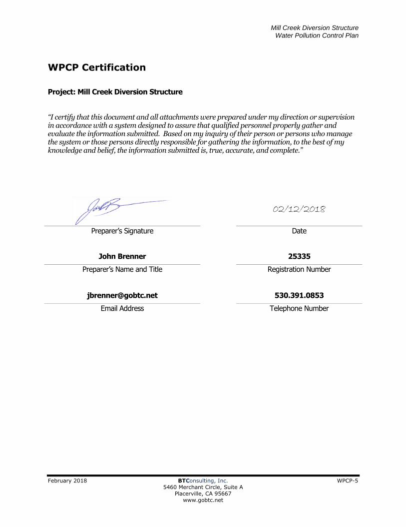
WPCP Certification
Project: Mill Creek Diversion Structure
“I certify that this document and all attachments were prepared under my direction or supervision in accordance with a system designed to assure that qualified personnel properly gather and evaluate the information submitted. Based on my inquiry of their person or persons who manage the system or those persons directly responsible for gathering the information, to the best of my knowledge and belief, the information submitted is, true, accurate, and complete.”
02/12/2018
Preparer’s Signature Date
John Brenner 25335
Preparer’s Name and Title Registration Number
[email protected] 530.391.0853
Email Address Telephone Number
Mill Creek Diversion Structure Water Pollution Control Plan
February 2018 BTConsulting, Inc. WPCP-6 5460 Merchant Circle, Suite A Placerville, CA 95667 www.gobtc.net
SECTION 1 WPCP Requirements
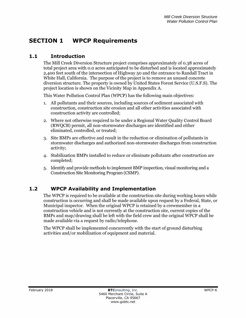
1.1 Introduction
The Mill Creek Diversion Structure project comprises approximately of 0.38 acres of total project area with 0.0 acres anticipated to be disturbed and is located approximately 2,400 feet south of the intersection of Highway 50 and the entrance to Randall Tract in White Hall, California. The purpose of the project is to remove an unused concrete diversion structure. The property is owned by United States Forest Service (U.S.F.S). The project location is shown on the Vicinity Map in Appendix A.
This Water Pollution Control Plan (WPCP) has the following main objectives:
1. All pollutants and their sources, including sources of sediment associated with construction, construction site erosion and all other activities associated with construction activity are controlled;
2. Where not otherwise required to be under a Regional Water Quality Control Board (RWQCB) permit, all non-stormwater discharges are identified and either eliminated, controlled, or treated;
3. Site BMPs are effective and result in the reduction or elimination of pollutants in stormwater discharges and authorized non-stormwater discharges from construction activity;
4. Stabilization BMPs installed to reduce or eliminate pollutants after construction are completed;
5. Identify and provide methods to implement BMP inspection, visual monitoring and a Construction Site Monitoring Program (CSMP).
1.2 WPCP Availability and Implementation
The WPCP is required to be available at the construction site during working hours while construction is occurring and shall be made available upon request by a Federal, State, or Municipal inspector. When the original WPCP is retained by a crewmember in a construction vehicle and is not currently at the construction site, current copies of the BMPs and map/drawing shall be left with the field crew and the original WPCP shall be made available via a request by radio/telephone.
The WPCP shall be implemented concurrently with the start of ground disturbing activities and/or mobilization of equipment and material.

Mill Creek Diversion Structure Water Pollution Control Plan
February 2018 BTConsulting, Inc. WPCP-7 5460 Merchant Circle, Suite A Placerville, CA 95667 www.gobtc.net
SECTION 2 Project Information
2.1 Project and Site Description
2.1.1 Project Description
The Mill Creek Diversion Structure Project is located 2,400 feet south of the intersection of Highway 50 and the entrance to Randall Tract, near White Hall, California. The project consists of removing a concrete diversion structure that was used in association with a former flume section. The project site is located in the flowline of Mill Creek. The project is expected to disturb less than an acre of land and the main projects features include demolition of the existing concrete diversion structure and removal of the waste concrete and other associated materials. Crews are anticipated to hike in from Randall Tract and most material, equipment, and waste is expected to be flown in and out by helicopter. Project construction is expected to be performed in one continuous phase.
2.1.2 Existing Conditions
As of the initial date of this WPCP, the project site is located in a mountainous steep draw up hill (south) of Randall Tract. Vegetation in the area consists of dense brush and trees and is moderate along the access path to the diversion structure due to maintenance clearing. Within the draw (Mill Creek) where the diversion structure will be demolished the vegetation is sparse and conditions are very rocky.
2.1.3 Existing Drainage
Stormwater runoff is conveyed to the north of the diversion structure via Mill Creek, which is tributary to the South Fork of the American River, located adjacent and parallel to Highway 50. The site slopes typically from the south to north.
2.1.4 Geology and Groundwater
The proposed staging area and the diversion structure area are located within the Mill Creek streambed which consists of bedrock at the surface with limited to no soil present. Soils in the area surrounding the project are classified as “Chaix coarse sandy loam, 30-75 percent slopes” according to the Custom Soil Resource Report included in Appendix C. These soils have a typical depth to the water table of more than 80 inches and are somewhat excessively well drained. The typical soil profile is as follows:
• 0 to 30 inches: Coarse Sandy Loam
• 30 to 60 inches: Weathered Bedrock
Mean annual precipitation for the site 40 to 65 inches.
2.1.5 Developed Condition
Post construction surface drainage will continue to flow as described prior to construction with the minor exception of the brief impoundment caused by the diversion structure.
2.2 Construction Schedule
Construction, consisting of demolition of the diversion structure and removal of all waste, is anticipated to be completed over the course of approximately one week during the late summer of 2019.

Mill Creek Diversion Structure Water Pollution Control Plan
February 2018 BTConsulting, Inc. WPCP-8 5460 Merchant Circle, Suite A Placerville, CA 95667 www.gobtc.net
2.3 Potential Construction Site Pollutant Sources
Construction materials that will be used and activities to be performed that have the potential to contribute pollutants other than sediment to stormwater runoff are identified in the table below.
Construction Activity Materials Associated Pollutants
BMP Installation Sandbags Sand
Clearing and Grubbing Vehicles/Equipment, Plant Material Vehicle Pollutants, Sediment
Concrete/Masonry Portland Cement, sealant, Ash, Steel Slag, Sand, Rinse Water
pH, alkalinity, methyl methacrylate, cobalt, zinc, aluminum, calcium, vanadium, VOC, SVOC
Contaminated Soil Petroleum, Other Oil, Petroleum, Other
General Litter Litter Project related trash
Portable Toilet Bacteria, disinfectants Chemicals and fecal coliform
Vehicles and Equipment Antifreeze, Batteries, Fuels, Oils, Lubricants, Other Vehicle Fluids
Sulfuric Acid, Lead, pH, Oil, Petroleum, Antifreeze

Mill Creek Diversion Structure Water Pollution Control Plan
February 2018 BTConsulting, Inc. WPCP-9 5460 Merchant Circle, Suite A Placerville, CA 95667 www.gobtc.net
2.4 Identification of Non-Stormwater Discharges
Potential Non-Stormwater Discharges for the project may include:
• Uncontaminated Ground Water or Creek Water from Dewatering
• Atmospheric Condensates Including: o Compressor Condensate
• Springs
The discharge of items listed above is authorized under the following conditions:
1. The discharge does not cause or contribute to a violation of any water quality standard;
2. The discharger has included and implemented specific BMPs to prevent or reduce the contact of the non-storm water discharge with construction materials and equipment.
3. The discharge does not contain toxic constituents in toxic amounts or other significant quantities of pollutants;
If any of the above conditions are not satisfied, the discharge is not authorized.
2.5 References
The following documents are made a part of this WPCP by reference:
• California Stormwater BMP Handbook – Construction, November 2009
All applicable Local, State, and Federal requirements shall also be enforced.

Mill Creek Diversion Structure Water Pollution Control Plan
February 2018 BTConsulting, Inc. WPCP-10 5460 Merchant Circle, Suite A Placerville, CA 95667 www.gobtc.net
SECTION 3 Best Management Practices
3.1 Schedule for BMP Implementation
BMPs must be implemented, modified, and maintained to reflect the phase of construction and the weather conditions. In order to be effective, some BMPs must be installed before the site is disturbed.
3.2 Erosion and Sediment Control
Erosion and sediment control, also referred to as soil stabilization, consists of source control measures that are designed to prevent soil particles from detaching and becoming transported in storm water runoff. Erosion and sediment control BMPs protect the soil surface by covering and/or binding soil particles. This project will incorporate erosion and sediment control measures required by the contract documents, and other measures selected by the Contractor.
This project may implement the following practices for effective temporary and final erosion and sediment control. Many of the erosion and sediment control BMPs are different options that serve the same purpose. For example: EC-3, Hydraulic Mulch, EC-6, Straw Mulch and EC-8, Wood Mulch can be used independently to serve the same purpose.
The following erosion and sediment control BMP selection tables indicate the BMPs that could be implemented to control erosion on the construction site. Fact Sheets for erosion and sediment control BMPs that describe the purpose, application, limitations, implementation, inspection, and maintenance are provided in Appendix B.
Additional BMPs, including those in the following table, may be determined necessary or appropriate as the project progresses.
Erosion Control BMPs
Fact
Sheet BMP Name Notes
EC-1 Scheduling Entire project at all times.
EC-2 Preservation of Existing Vegetation Entire project at all times.
EC-7 Geotextiles and Mats To be used if land disturbance occurs.
Possible option for stockpile cover if needed.
WE-1 Wind Erosion Control Entire project at all times.

Mill Creek Diversion Structure Water Pollution Control Plan
February 2018 BTConsulting, Inc. WPCP-11 5460 Merchant Circle, Suite A Placerville, CA 95667 www.gobtc.net
Sediment Control BMPs
Fact Sheet
BMP Name Notes
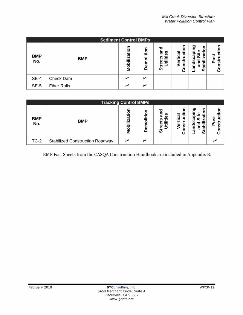
SE-4 Check Dams To be used for sediment control during demolition.
SE-5 Fiber Rolls To be used for staging area perimeter control.
TC-2 Stabilized Construction Roadway Utilize existing road through Randall Tract or other similar access route.
BMPs shall be installed and maintained during specific phases and timing. The tables below illustrate the schedule for the installation and maintenance for each BMP. BMPs shall be installed, maintained, repaired, and/or replaced as necessary during the phase in which they are to be used. Unless BMPs are used for multiple phases or post construction, BMPs shall be removed and properly discarded following the intended phase(s).
Erosion Control BMP Implementation Schedule
BMP No.
BMP
Mo
biliz
ati
on
De
mo
liti
on
Str
ee
ts a
nd
Uti
liti
es
Ve
rtic
al
Co
ns
tru
cti
on
Lan
dscap
ing
an
d S
ite
Sta
biliz
ati
on
Po
st
Co
ns
tru
cti
on
EC-1 Scheduling
EC-2 Preservation of Existing Vegetation
EC-7 Geotextiles & Mats
Wind Erosion Control BMPs
BMP No.
BMP
Mo
biliz
ati
on
De
mo
liti
on
Str
ee
ts a
nd
Uti
liti
es
Ve
rtic
al
Co
ns
tru
cti
on
Lan
dscap
ing
an
d S
ite
Sta
biliz
ati
on
Po
st
Co
ns
tru
cti
on
WE-1 Wind Erosion Control
Mill Creek Diversion Structure Water Pollution Control Plan
February 2018 BTConsulting, Inc. WPCP-12 5460 Merchant Circle, Suite A Placerville, CA 95667 www.gobtc.net
Sediment Control BMPs
BMP No.
BMP
Mo
biliz
ati
on
De
mo
liti
on
Str
ee
ts a
nd
Uti
liti
es
Ve
rtic
al
Co
ns
tru
cti
on
Lan
dscap
ing
an
d S
ite
Sta
biliz
ati
on
Po
st
Co
ns
tru
cti
on
SE-4 Check Dam
SE-5 Fiber Rolls
Tracking Control BMPs
BMP No.
BMP
Mo
biliz
ati
on
D
em
oliti
on
Str
ee
ts a
nd
Uti
liti
es
Ve
rtic
al
Co
ns
tru
cti
on
Lan
dscap
ing
an
d S
ite
Sta
biliz
ati
on
Po
st
Co
ns
tru
cti
on
TC-2 Stabilized Construction Roadway
BMP Fact Sheets from the CASQA Construction Handbook are included in Appendix B.

Mill Creek Diversion Structure Water Pollution Control Plan
February 2018 BTConsulting, Inc. WPCP-13 5460 Merchant Circle, Suite A Placerville, CA 95667 www.gobtc.net
3.3 Non-Stormwater and Materials Management
This section of the WPCP is designed to address the following objective: to identify all non-stormwater discharges and that discharges be eliminated, controlled, or treated. Selected Non-Stormwater and Materials Management BMPs include those listed in the tables below.
The following non-stormwater control and materials management BMP selection tables indicate the BMPs that could be implemented to control potential pollutants on the construction site. Fact Sheets for temporary non-stormwater control and materials management BMPs that describe the purpose, application, limitations, implementation, inspection, and maintenance are provided in Appendix B.
Non-Stormwater BMPs
Fact Sheet BMP Name Notes
NS-1 Water Conservation Practices Entire project at all times.
NS-4 Temporary Stream Crossing Utilize any applicable measures described in the fact sheet.
NS-5 Clear Water Diversion Install in Mill Creek while demolition is occurring.
NS-6 Illicit Connection/Discharge Not anticipated but there is potential for accidental discharge.
NS-8 Vehicle and Equipment Cleaning Prohibited on this site.
NS-9 Vehicle and Equipment Fueling In the staging area if possible and if necessary.
NS-10 Vehicle and Equipment Maintenance In the staging area if possible and if necessary.
NS-14 Material and Equipment Use Over Water While demolition is occurring.
NS-15 Demolition Removal Adjacent to Water While demolition is occurring.
Temporary Materials Management BMPs
Fact
Sheet BMP Name Notes
WM-01 Material Delivery and Storage Entire project at all times.
WM-02 Material Use Entire project at all times.
WM-03 Stockpile Management Entire project at all times.

Mill Creek Diversion Structure Water Pollution Control Plan
February 2018 BTConsulting, Inc. WPCP-14 5460 Merchant Circle, Suite A Placerville, CA 95667 www.gobtc.net
Temporary Materials Management BMPs
Fact
Sheet BMP Name Notes
WM-04 Spill Prevention and Control Entire project at all times.
WM-05 Solid Waste Management Entire project at all times.
WM-07 Contaminated Soil Management Not anticipated but utilize applicable measures if created or discovered.
WM-08 Concrete Waste Management Entire project at all times.
WM-09 Sanitary-Septic Waste Management Entire project at all times.
WM-10 Liquid Waste Management In the staging area if possible and if necessary.
BMPs shall be installed and maintained during specific phases and timing. The tables below illustrate the schedule for the installation and maintenance for each BMP. BMPs shall be installed, maintained, repaired, and/or replaced as necessary during the phase in which they are to be used. Unless BMPs are used for multiple phases or post construction, BMPs shall be removed and properly discarded following the intended phase(s).
Non-Stormwater Management BMPs
BMP No.
BMP
Mo
biliz
ati
on
De
mo
liti
on
Str
ee
ts a
nd
Uti
liti
es
Ve
rtic
al
Co
ns
tru
cti
on
Lan
dscap
ing
an
d S
ite
Sta
biliz
ati
on
Po
st
Co
ns
tru
cti
on
NS-1 Water Conservation Practices
NS-4 Temporary Stream Crossing
NS-5 Clear Water Diversion
NS-6 Illicit Connection/Discharge
NS-9 Vehicle and Equipment Fueling
NS-10 Vehicle and Equipment Maintenance
NS-14 Material Over Water
NS-15 Demolition Adjacent to Water

Mill Creek Diversion Structure Water Pollution Control Plan
February 2018 BTConsulting, Inc. WPCP-15 5460 Merchant Circle, Suite A Placerville, CA 95667 www.gobtc.net
Waste Management and Materials Pollution Control BMPs
BMP No.
BMP
Mo
biliz
ati
on
De
mo
liti
on
Str
ee
ts a
nd
Uti
liti
es
Ve
rtic
al
Co
ns
tru
cti
on
Lan
dscap
ing
an
d S
ite
Sta
biliz
ati
on
Po
st
Co
ns
tru
cti
on
WM-1 Material Delivery and Storage
WM-2 Material Use
WM-3 Stockpile Management
WM-4 Spill Prevention and Control
WM-5 Solid Waste Management
WM-7 Contaminated Soil Management
WM-8 Concrete Waste Management
WM-9 Sanitary/Septic Waste Management
WM-10 Liquid Waste Management
BMP Fact Sheets from the CASQA Construction Handbook are included in Appendix B. BMPs shall be installed and maintained as directed in the Fact Sheets.
All stored construction equipment and materials that are required for the project shall be kept within the Staging Area. Equipment fueling and maintenance shall be conducted in the Staging Area and shall be conducted as directed in the Fact Sheets. The boundary or down gradient side of the Staging Area shall be protected by an Fiber Roll (SE-5) or similar. Spill clean-up materials shall be stored in the Staging Area. Materials should include but are not limited to oil absorbent pads, socks/booms, and dry absorbent. Used spill clean-up materials must be disposed of properly.
3.4 Post-Construction Stormwater Management Measures
BMPs will be implemented to reduce pollutants in stormwater discharges that are reasonably foreseeable after all construction phases have been completed at the site. Project post-construction stormwater management measures include:
• Land disturbance is not anticipated for this project. If soil is disturbed it shall be stabilized to pre-construction conditions using rolled erosion control blankets that do not contain plastic mesh, mulch, and/or seed.

SECTION 4 BMP Inspection and Maintenance
4.1 BMP Inspection and Maintenance
Visual monitoring includes observations and inspections. Inspections of BMPs are required to identify and record BMPs that need maintenance to operate effectively, that have failed, or that could fail to operate as intended. Visual observations of the site are required to observe storm water drainage areas to identify any spills, leaks, or uncontrolled pollutant sources.
Inspections will be conducted as follows:
• Daily while demolition is occurring and/or during mobilization
• Before any storm with a 50% chance or better rainfall prediction
• Every 24 hours during and extended rain event
• Within 48 hours after a rain event producing more than ½” of precipitation
A blank inspection form is provided in Appendix E. Completed inspection forms shall be added to Appendix F and shall be readily accessible on site.
Some BMPs (e.g. tracking controls) may require daily monitoring. BMPs must be maintained regularly based on observations.
Implementation of corrective actions should begin within 72 hours for deficiencies identified during inspections.
SECTION 5 Training Personnel at the site shall receive training appropriate for individual roles and responsibilities on the project. Appropriate personnel shall receive training on WPCP implementation, BMP inspection and maintenance, and record keeping. Document all training activities (formal and informal) and retained a record of training activities in Appendix D.
All persons responsible for implementing requirements of this WPCP shall be appropriately trained. Training should be both formal and informal, occur on an ongoing basis, and should include training offered by recognized governmental agencies or professional organizations.

Mill Creek Diversion Structure Water Pollution Control Plan
February 2018 BTConsulting, Inc. WPCP-17 5460 Merchant Circle, Suite A Placerville, CA 95667 www.gobtc.net
(916) 834-5019
John Brenner, QSD/QSP
Phil Springer, QSP
Cary Mutschler (530) 642-4182
(530) 391-0853
SECTION 6 Responsible Parties and Operators
6.1 Responsible Parties
Owner’s Representative
_______________________________________________________________________________________ ___________________________________________________________________________________
Name & Title Phone Number
WPCP Monitor/Inspector
____________________________________________________________________________________________ ___________________________________________________________________________________
Name & Title Phone Number
WPCP Developer/WPCM
____________________________________________________________________________________________ ___________________________________________________________________________________
Name & Title Phone Number
The WPCM shall have primary responsibility and significant authority for the implementation,
maintenance and inspection of this WPCP. The WPCM will be available at all times
throughout the duration of the project. Duties of the WPCM include but are not
limited to:
▪ Ensuring full compliance with the WPCP and local requirements.
▪ Implementing all elements of the WPCP including implementation of
erosion and sediment control measures, non-storm water management,
and materials and waste management.
▪ Inspections.
▪ Ensuring eliminiation of all unauthorized discharges.
▪ The WPCM shall be assigned authority to mobilize crews in order to make
immediate repairs to control measures.

Mill Creek Diversion Structure Water Pollution Control Plan
February 2018 BTConsulting, Inc. WPCP-18 5460 Merchant Circle, Suite A Placerville, CA 95667 www.gobtc.net
6.2 Contractor List
This WPCP shall include a list of names of all contractors, subcontractors, and individuals who will be directed by the WPCM. The Contractor List for this project is provided in the table on the following page.

Contractor and Subcontractor Table
SUBCONTRACTOR
COMPANY NAME
CONTACT
NAME
ADDRESS
PHONE
NUMBER
EMERGENCY
PHONE
AREA OF RESPONSIBILITY
BTConsulting, Inc. John Brenner 5460 Merchant Circle Placerville, CA 95667
(530) 391-0853 (530) 672-2316 Stormwater
Pending Prime Contractor

SECTION 7 Construction Site Monitoring Program
7.1 Purpose
The Construction Site Monitoring Program (CSMP) is developed as a guide for monitoring of the construction site.
7.2 Monitoring Locations
Monitoring locations shall be based on BMP locations, discharge or run-on location(s), personnel Safety, and other factors.
All Sites should monitor runoff for non-visible pollutants in the event of a BMP failure, breach, or spill. An area unaffected by the failure, breach, or spill must also be sampled to serve as the basis of comparison.
If warranted, run-on sampling locations should be located upstream of all direct discharge from the construction site for the collection of a control sample to be analyzed for the prevailing condition of the receiving water without any influence from the construction site.
If warranted, run-off sampling locations should be located immediately downstream from the last point of discharge from the construction site for the collection of a sample to be analyzed for potential increases in pH, Turbidity, and potential non-visible pollutants. This sample should characterize discharges associated with construction activity from the entire project disturbed area.
7.3 Safety
Visual observation (inspections) are not required under the following conditions:
During dangerous weather conditions such as flooding and electrical storms.
Outside of scheduled site business hours.
If monitoring of the site is unsafe because of the dangerous conditions noted above, the Inspector shall document the conditions for why an exception to performing the monitoring was necessary.
A summary of the safety concerns that apply to inspection personnel are provided below.
• Steep Slopes
• Active construction equipment
• Trip and fall hazards
• Wet or muddy surfaces
• Wild animals, domestic dogs, snakes, bees, ticks, etc.

Mill Creek Diversion Structure Water Pollution Control Plan
February 2018 BTConsulting, Inc. WPCP-21 5460 Merchant Circle, Suite A Placerville, CA 95667 www.gobtc.net
7.4 Visual Monitoring (Inspections)
Routine inspections require visual observation of site related BMPs to determine if the BMPs are adequately implemented and effective.
Pre-storm event inspections require visual observation of BMPs to determine in the BMPs were properly installed, are failing, or may fail to operate as intended during the predicted rain event.
Storm-related inspections require visual observation of BMPs and storm water discharges at all discharge locations.
Post-storm event inspections require identification of whether BMPS were adequately designed, implemented, and effective and identification of any additional BMPs necessary.
Inspection frequencies are listed in Section 4.1 of this WPCP.
Inspection forms are located in Appendix E.

Appendix A
Site Maps


Appendix B
BMP Fact Sheets

Scheduling EC-1
November 2009 California Stormwater BMP Handbook 1 of 3 Construction www.casqa.org
Description and Purpose Scheduling is the development of a written plan that includes sequencing of construction activities and the implementation of BMPs such as erosion control and sediment control while taking local climate (rainfall, wind, etc.) into consideration. The purpose is to reduce the amount and duration of soil exposed to erosion by wind, rain, runoff, and vehicle tracking, and to perform the construction activities and control practices in accordance with the planned schedule.
Suitable Applications Proper sequencing of construction activities to reduce erosion potential should be incorporated into the schedule of every construction project especially during rainy season. Use of other, more costly yet less effective, erosion and sediment control BMPs may often be reduced through proper construction sequencing.
Limitations Environmental constraints such as nesting season
prohibitions reduce the full capabilities of this BMP.
Implementation Avoid rainy periods. Schedule major grading operations
during dry months when practical. Allow enough time before rainfall begins to stabilize the soil with vegetation or physical means or to install sediment trapping devices.
Plan the project and develop a schedule showing each phase of construction. Clearly show how the rainy season relates
Categories
EC Erosion Control
SE Sediment Control
TC Tracking Control
WE Wind Erosion Control
NS Non-Stormwater Management Control
WM Waste Management and Materials Pollution Control
Legend:
Primary Objective
Secondary Objective
Targeted Constituents
Sediment Nutrients Trash Metals Bacteria Oil and Grease Organics
Potential Alternatives
None
If User/Subscriber modifies this fact sheet in any way, the CASQA name/logo and footer below must be removed from each page and not appear on the modified version.

Scheduling EC-1
November 2009 California Stormwater BMP Handbook 2 of 3 Construction www.casqa.org
to soil disturbing and re-stabilization activities. Incorporate the construction schedule into the SWPPP.
Include on the schedule, details on the rainy season implementation and deployment of:
Erosion control BMPs
Sediment control BMPs
Tracking control BMPs
Wind erosion control BMPs
Non-stormwater BMPs
Waste management and materials pollution control BMPs
Include dates for activities that may require non-stormwater discharges such as dewatering, sawcutting, grinding, drilling, boring, crushing, blasting, painting, hydro-demolition, mortar mixing, pavement cleaning, etc.
Work out the sequencing and timetable for the start and completion of each item such as site clearing and grubbing, grading, excavation, paving, foundation pouring utilities installation, etc., to minimize the active construction area during the rainy season.
Sequence trenching activities so that most open portions are closed before new trenching begins.
Incorporate staged seeding and re-vegetation of graded slopes as work progresses.
Schedule establishment of permanent vegetation during appropriate planting time for specified vegetation.
Non-active areas should be stabilized as soon as practical after the cessation of soil disturbing activities or one day prior to the onset of precipitation.
Monitor the weather forecast for rainfall.
When rainfall is predicted, adjust the construction schedule to allow the implementation of soil stabilization and sediment treatment controls on all disturbed areas prior to the onset of rain.
Be prepared year round to deploy erosion control and sediment control BMPs. Erosion may be caused during dry seasons by un-seasonal rainfall, wind, and vehicle tracking. Keep the site stabilized year round, and retain and maintain rainy season sediment trapping devices in operational condition.
Apply permanent erosion control to areas deemed substantially complete during the project’s defined seeding window.
Costs Construction scheduling to reduce erosion may increase other construction costs due to reduced economies of scale in performing site grading. The cost effectiveness of scheduling techniques should be compared with the other less effective erosion and sedimentation controls to achieve a cost effective balance.

Scheduling EC-1
November 2009 California Stormwater BMP Handbook 3 of 3 Construction www.casqa.org
Inspection and Maintenance Verify that work is progressing in accordance with the schedule. If progress deviates, take
corrective actions.
Amend the schedule when changes are warranted.
Amend the schedule prior to the rainy season to show updated information on the deployment and implementation of construction site BMPs.
References Stormwater Quality Handbooks Construction Site Best Management Practices (BMPs) Manual, State of California Department of Transportation (Caltrans), November 2000.
Stormwater Management for Construction Activities Developing Pollution Prevention Plans and Best Management Practices (EPA 832-R-92-005), U.S. Environmental Protection Agency, Office of Water, September 1992.

Preservation Of Existing Vegetation EC-2
November 2009 California Stormwater BMP Handbook 1 of 4 Construction www.casqa.org
Description and Purpose Carefully planned preservation of existing vegetation minimizes the potential of removing or injuring existing trees, vines, shrubs, and grasses that protect soil from erosion.
Suitable Applications Preservation of existing vegetation is suitable for use on most projects. Large project sites often provide the greatest opportunity for use of this BMP. Suitable applications include the following:
Areas within the site where no construction activity occurs, or occurs at a later date. This BMP is especially suitable to multi year projects where grading can be phased.
Areas where natural vegetation exists and is designated for preservation. Such areas often include steep slopes, watercourse, and building sites in wooded areas.
Areas where local, state, and federal government require preservation, such as vernal pools, wetlands, marshes, certain oak trees, etc. These areas are usually designated on the plans, or in the specifications, permits, or environmental documents.
Where vegetation designated for ultimate removal can be temporarily preserved and be utilized for erosion control and sediment control.
Categories
EC Erosion Control
SE Sediment Control
TC Tracking Control
WE Wind Erosion Control
NS Non-Stormwater Management Control
WM Waste Management and Materials Pollution Control
Legend:
Primary Objective
Secondary Objective
Targeted Constituents
Sediment Nutrients Trash Metals Bacteria Oil and Grease Organics
Potential Alternatives
None
If User/Subscriber modifies this fact sheet in any way, the CASQA name/logo and footer below must be removed from each page and not appear on the modified version.
Preservation Of Existing Vegetation EC-2
November 2009 California Stormwater BMP Handbook 2 of 4 Construction www.casqa.org
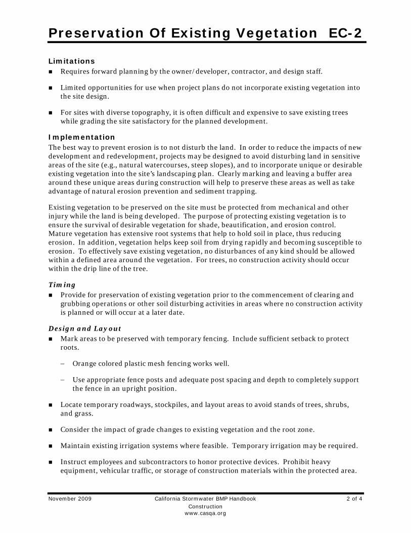
Limitations Requires forward planning by the owner/developer, contractor, and design staff.
Limited opportunities for use when project plans do not incorporate existing vegetation into the site design.
For sites with diverse topography, it is often difficult and expensive to save existing trees while grading the site satisfactory for the planned development.
Implementation The best way to prevent erosion is to not disturb the land. In order to reduce the impacts of new development and redevelopment, projects may be designed to avoid disturbing land in sensitive areas of the site (e.g., natural watercourses, steep slopes), and to incorporate unique or desirable existing vegetation into the site’s landscaping plan. Clearly marking and leaving a buffer area around these unique areas during construction will help to preserve these areas as well as take advantage of natural erosion prevention and sediment trapping.
Existing vegetation to be preserved on the site must be protected from mechanical and other injury while the land is being developed. The purpose of protecting existing vegetation is to ensure the survival of desirable vegetation for shade, beautification, and erosion control. Mature vegetation has extensive root systems that help to hold soil in place, thus reducing erosion. In addition, vegetation helps keep soil from drying rapidly and becoming susceptible to erosion. To effectively save existing vegetation, no disturbances of any kind should be allowed within a defined area around the vegetation. For trees, no construction activity should occur within the drip line of the tree.
Timing Provide for preservation of existing vegetation prior to the commencement of clearing and
grubbing operations or other soil disturbing activities in areas where no construction activity is planned or will occur at a later date.
Design and Layout Mark areas to be preserved with temporary fencing. Include sufficient setback to protect
roots.
− Orange colored plastic mesh fencing works well.
− Use appropriate fence posts and adequate post spacing and depth to completely support the fence in an upright position.
Locate temporary roadways, stockpiles, and layout areas to avoid stands of trees, shrubs, and grass.
Consider the impact of grade changes to existing vegetation and the root zone.
Maintain existing irrigation systems where feasible. Temporary irrigation may be required.
Instruct employees and subcontractors to honor protective devices. Prohibit heavy equipment, vehicular traffic, or storage of construction materials within the protected area.

Preservation Of Existing Vegetation EC-2
November 2009 California Stormwater BMP Handbook 3 of 4 Construction www.casqa.org
Costs There is little cost associated with preserving existing vegetation if properly planned during the project design, and these costs may be offset by aesthetic benefits that enhance property values. During construction, the cost for preserving existing vegetation will likely be less than the cost of applying erosion and sediment controls to the disturbed area. Replacing vegetation inadvertently destroyed during construction can be extremely expensive, sometimes in excess of $10,000 per tree.
Inspection and Maintenance During construction, the limits of disturbance should remain clearly marked at all times. Irrigation or maintenance of existing vegetation should be described in the landscaping plan. If damage to protected trees still occurs, maintenance guidelines described below should be followed:
Verify that protective measures remain in place. Restore damaged protection measures immediately.
Serious tree injuries shall be attended to by an arborist.
Damage to the crown, trunk, or root system of a retained tree shall be repaired immediately.
Trench as far from tree trunks as possible, usually outside of the tree drip line or canopy. Curve trenches around trees to avoid large roots or root concentrations. If roots are encountered, consider tunneling under them. When trenching or tunneling near or under trees to be retained, place tunnels at least 18 in. below the ground surface, and not below the tree center to minimize impact on the roots.
Do not leave tree roots exposed to air. Cover exposed roots with soil as soon as possible. If soil covering is not practical, protect exposed roots with wet burlap or peat moss until the tunnel or trench is ready for backfill.
Cleanly remove the ends of damaged roots with a smooth cut.
Fill trenches and tunnels as soon as possible. Careful filling and tamping will eliminate air spaces in the soil, which can damage roots.
If bark damage occurs, cut back all loosened bark into the undamaged area, with the cut tapered at the top and bottom and drainage provided at the base of the wood. Limit cutting the undamaged area as much as possible.
Aerate soil that has been compacted over a trees root zone by punching holes 12 in. deep with an iron bar, and moving the bar back and forth until the soil is loosened. Place holes 18 in. apart throughout the area of compacted soil under the tree crown.
Fertilization
− Fertilize stressed or damaged broadleaf trees to aid recovery.
− Fertilize trees in the late fall or early spring.
Preservation Of Existing Vegetation EC-2
November 2009 California Stormwater BMP Handbook 4 of 4 Construction www.casqa.org
Apply fertilizer to the soil over the feeder roots and in accordance with label instructions, but never closer than 3 ft to the trunk. Increase the fertilized area by one-fourth of the crown area for conifers that have extended root systems.
Retain protective measures until all other construction activity is complete to avoid damage during site cleanup and stabilization.
References County of Sacramento Tree Preservation Ordinance, September 1981.
Stormwater Quality Handbooks Construction Site Best Management Practices (BMPs) Manual, State of California Department of Transportation (Caltrans), November 2000.
Stormwater Management of the Puget Sound Basin, Technical Manual, Publication #91-75, Washington State Department of Ecology, February 1992.
Water Quality Management Plan for The Lake Tahoe Region, Volume II, Handbook of Management Practices, Tahoe Regional Planning Agency, November 1988.

Geotextiles and Mats EC-7
July 2012 California Stormwater BMP Handbook 1 of 12
Construction
www.casqa.org
Description and Purpose
Mattings, or Rolled Erosion Control Products (RECPs), can be made of natural or synthetic materials or a combination of the two. RECPs are used to cover the soil surface to reduce erosion from rainfall impact, hold soil in place, and absorb and hold moisture near the soil surface. Additionally, RECPs may be used to stabilize soils until vegetation is established or to reinforce non-woody surface vegetation.
Suitable Applications
RECPs are typically applied on slopes where erosion hazard is high and vegetation will be slow to establish. Mattings are also used on stream banks, swales and other drainage channels where moving water at velocities between 3 ft/s and 6 ft/s are likely to cause scour and wash out new vegetation, and in areas where the soil surface is disturbed and where existing vegetation has been removed. RECPs may also be used when seeding cannot occur (e.g., late season construction and/or the arrival of an early rain season). RECPs should be considered when the soils are fine grained and potentially erosive. RECPs should be considered in the following situations.
Steep slopes, generally steeper than 3:1 (H:V)
Slopes where the erosion potential is high
Slopes and disturbed soils where mulch must be anchored
Disturbed areas where plants are slow to develop
Categories
EC Erosion Control
SE Sediment Control
TC Tracking Control
WE Wind Erosion Control
NS Non-Stormwater Management Control
WM Waste Management and Materials Pollution Control
Legend:
Primary Category
Secondary Category
Targeted Constituents
Sediment
Nutrients
Trash
Metals
Bacteria
Oil and Grease
Organics
Potential Alternatives
EC-3 Hydraulic Mulch
EC-4 Hydroseeding
If User/Subscriber modifies this fact sheet in any way, the CASQA name/logo and footer below must be removed from each page and not appear on the modified version.

Geotextiles and Mats EC-7
July 2012 California Stormwater BMP Handbook 2 of 12
Construction
www.casqa.org
Channels with flows exceeding 3.3 ft/s
Channels to be vegetated
Stockpiles
Slopes adjacent to water bodies
Limitations
RECP installed costs are generally higher than other erosion control BMPs, limiting their use to areas where other BMPs are ineffective (e.g. channels, steep slopes).
RECPs may delay seed germination, due to reduction in soil temperature.
RECPs are generally not suitable for excessively rocky sites or areas where the final vegetation will be mowed (since staples and netting can catch in mowers). If a staple or pin cannot be driven into the soil because the underlying soil is too hard or rocky, then an alternative BMP should be selected.
If used for temporary erosion control, RECPs should be removed and disposed of prior to application of permanent soil stabilization measures.
The use of plastic should be limited to covering stockpiles or very small graded areas for short periods of time (such as through one imminent storm event) until more environmentally friendly measures, such as seeding and mulching, may be installed.
- Plastic sheeting is easily vandalized, easily torn, photodegradable, and must be disposed of at a landfill.
- Plastic sheeting results in 100% runoff, which may cause serious erosion problems in the areas receiving the increased flow.
RECPs may have limitations based on soil type, slope gradient, or channel flow rate; consult the manufacturer for proper selection.
Not suitable for areas that have foot traffic (tripping hazard) – e.g., pad areas around buildings under construction.
RECPs that incorporate a plastic netting (e.g. straw blanket typically uses a plastic netting to hold the straw in place) may not be suitable near known wildlife habitat. Wildlife can become trapped in the plastic netting.
RECPs may have limitations in extremely windy climates. However, when RECPs are properly trenched at the top and bottom and stapled in accordance with the manufacturer’s recommendations, problems with wind can be minimized.
Geotextiles and Mats EC-7
July 2012 California Stormwater BMP Handbook 3 of 12
Construction
www.casqa.org
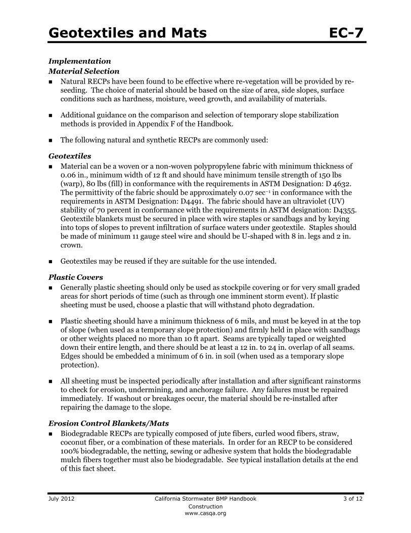
Implementation
Material Selection
Natural RECPs have been found to be effective where re-vegetation will be provided by re-seeding. The choice of material should be based on the size of area, side slopes, surface conditions such as hardness, moisture, weed growth, and availability of materials.
Additional guidance on the comparison and selection of temporary slope stabilization methods is provided in Appendix F of the Handbook.
The following natural and synthetic RECPs are commonly used:
Geotextiles
Material can be a woven or a non-woven polypropylene fabric with minimum thickness of 0.06 in., minimum width of 12 ft and should have minimum tensile strength of 150 lbs (warp), 80 lbs (fill) in conformance with the requirements in ASTM Designation: D 4632. The permittivity of the fabric should be approximately 0.07 sec–1 in conformance with the requirements in ASTM Designation: D4491. The fabric should have an ultraviolet (UV) stability of 70 percent in conformance with the requirements in ASTM designation: D4355. Geotextile blankets must be secured in place with wire staples or sandbags and by keying into tops of slopes to prevent infiltration of surface waters under geotextile. Staples should be made of minimum 11 gauge steel wire and should be U-shaped with 8 in. legs and 2 in. crown.
Geotextiles may be reused if they are suitable for the use intended.
Plastic Covers
Generally plastic sheeting should only be used as stockpile covering or for very small graded areas for short periods of time (such as through one imminent storm event). If plastic sheeting must be used, choose a plastic that will withstand photo degradation.
Plastic sheeting should have a minimum thickness of 6 mils, and must be keyed in at the top of slope (when used as a temporary slope protection) and firmly held in place with sandbags or other weights placed no more than 10 ft apart. Seams are typically taped or weighted down their entire length, and there should be at least a 12 in. to 24 in. overlap of all seams. Edges should be embedded a minimum of 6 in. in soil (when used as a temporary slope protection).
All sheeting must be inspected periodically after installation and after significant rainstorms to check for erosion, undermining, and anchorage failure. Any failures must be repaired immediately. If washout or breakages occur, the material should be re-installed after repairing the damage to the slope.
Erosion Control Blankets/Mats
Biodegradable RECPs are typically composed of jute fibers, curled wood fibers, straw, coconut fiber, or a combination of these materials. In order for an RECP to be considered 100% biodegradable, the netting, sewing or adhesive system that holds the biodegradable mulch fibers together must also be biodegradable. See typical installation details at the end of this fact sheet.

Geotextiles and Mats EC-7
July 2012 California Stormwater BMP Handbook 4 of 12
Construction
www.casqa.org
Jute is a natural fiber that is made into a yarn that is loosely woven into a biodegradable mesh. The performance of jute as a stand-alone RECP is low. Most other RECPs outperform jute as a temporary erosion control product and therefore jute is not commonly used. It is designed to be used in conjunction with vegetation. The material is supplied in rolled strips, which should be secured to the soil with U-shaped staples or stakes in accordance with manufacturers’ recommendations.
Excelsior (curled wood fiber) blanket material should consist of machine produced mats of curled wood excelsior with 80 percent of the fiber 6 in. or longer. The excelsior blanket should be of consistent thickness. The wood fiber must be evenly distributed over the entire area of the blanket. The top surface of the blanket should be covered with a photodegradable extruded plastic mesh. The blanket should be smolder resistant without the use of chemical additives and should be non-toxic and non-injurious to plant and animal life. Excelsior blankets should be furnished in rolled strips, a minimum of 48 in. wide, and should have an average weight of 0.8 lb/yd2, 10 percent, at the time of manufacture. Excelsior blankets must be secured in place with wire staples. Staples should be made of minimum 11 gauge steel wire and should be U-shaped with 8 in. legs and 2 in. crown.
Straw blanket should be machine produced mats of straw with a lightweight biodegradable netting top layer. The straw should be attached to the netting with biodegradable thread or glue strips. The straw blanket should be of consistent thickness. The straw should be evenly distributed over the entire area of the blanket. Straw blanket should be furnished in rolled strips a minimum of 6.5 ft wide, a minimum of 80 ft long and a minimum of 0.5 lb/yd2. Straw blankets must be secured in place with wire staples. Staples should be made of minimum 11 gauge steel wire and should be U-shaped with 8 in. legs and 2 in. crown.
Wood fiber blanket is composed of biodegradable fiber mulch with extruded plastic netting held together with adhesives. The material is designed to enhance re-vegetation. The material is furnished in rolled strips, which must be secured to the ground with U-shaped staples or stakes in accordance with manufacturers’ recommendations.
Coconut fiber blanket should be a machine produced mat of 100 percent coconut fiber with biodegradable netting on the top and bottom. The coconut fiber should be attached to the netting with biodegradable thread or glue strips. The coconut fiber blanket should be of consistent thickness. The coconut fiber should be evenly distributed over the entire area of the blanket. Coconut fiber blanket should be furnished in rolled strips with a minimum of 6.5 ft wide, a minimum of 80 ft. long and a minimum of 0.5 lb/yd2. Coconut fiber blankets must be secured in place with wire staples. Staples should be made of minimum 11 gauge steel wire and should be U-shaped with 8 in. legs and 2 in. crown.
Coconut fiber mesh is a thin permeable membrane made from coconut or corn fiber that is spun into a yarn and woven into a biodegradable mat. It is designed to be used in conjunction with vegetation and typically has longevity of several years. The material is supplied in rolled strips, which must be secured to the soil with U-shaped staples or stakes in accordance with manufacturers’ recommendations.

Geotextiles and Mats EC-7
July 2012 California Stormwater BMP Handbook 5 of 12
Construction
www.casqa.org
Straw coconut fiber blanket should be machine produced mats of 70 percent straw and 30 percent coconut fiber with a biodegradable netting top layer and a biodegradable bottom net. The straw and coconut fiber should be attached to the netting with biodegradable thread or glue strips. The straw coconut fiber blanket should be of consistent thickness. The straw and coconut fiber should be evenly distributed over the entire area of the blanket. Straw coconut fiber blanket should be furnished in rolled strips a minimum of 6.5 ft wide, a minimum of 80 ft long and a minimum of 0.5 lb/yd2. Straw coconut fiber blankets must be secured in place with wire staples. Staples should be made of minimum 11 gauge steel wire and should be U-shaped with 8 in. legs and 2 in. crown.
Non-biodegradable RECPs are typically composed of polypropylene, polyethylene, nylon or other synthetic fibers. In some cases, a combination of biodegradable and synthetic fibers is used to construct the RECP. Netting used to hold these fibers together is typically non-biodegradable as well.
Plastic netting is a lightweight biaxially oriented netting designed for securing loose mulches like straw or paper to soil surfaces to establish vegetation. The netting is photodegradable. The netting is supplied in rolled strips, which must be secured with U-shaped staples or stakes in accordance with manufacturers’ recommendations.
Plastic mesh is an open weave geotextile that is composed of an extruded synthetic fiber woven into a mesh with an opening size of less than ¼ in. It is used with re-vegetation or may be used to secure loose fiber such as straw to the ground. The material is supplied in rolled strips, which must be secured to the soil with U-shaped staples or stakes in accordance with manufacturers’ recommendations.
Synthetic fiber with netting is a mat that is composed of durable synthetic fibers treated to resist chemicals and ultraviolet light. The mat is a dense, three dimensional mesh of synthetic (typically polyolefin) fibers stitched between two polypropylene nets. The mats are designed to be re-vegetated and provide a permanent composite system of soil, roots, and geomatrix. The material is furnished in rolled strips, which must be secured with U-shaped staples or stakes in accordance with manufacturers’ recommendations.
Bonded synthetic fibers consist of a three dimensional geomatrix nylon (or other synthetic) matting. Typically it has more than 90 percent open area, which facilitates root growth. It’s tough root reinforcing system anchors vegetation and protects against hydraulic lift and shear forces created by high volume discharges. It can be installed over prepared soil, followed by seeding into the mat. Once vegetated, it becomes an invisible composite system of soil, roots, and geomatrix. The material is furnished in rolled strips that must be secured with U-shaped staples or stakes in accordance with manufacturers’ recommendations.
Combination synthetic and biodegradable RECPs consist of biodegradable fibers, such as wood fiber or coconut fiber, with a heavy polypropylene net stitched to the top and a high strength continuous filament geomatrix or net stitched to the bottom. The material is designed to enhance re-vegetation. The material is furnished in rolled strips,

Geotextiles and Mats EC-7
July 2012 California Stormwater BMP Handbook 6 of 12
Construction
www.casqa.org
which must be secured with U-shaped staples or stakes in accordance with manufacturers’ recommendations.
Site Preparation
Proper soil preparation is essential to ensure complete contact of the RECP with the soil. Soil Roughening is not recommended in areas where RECPs will be installed.
Grade and shape the area of installation.
Remove all rocks, clods, vegetation or other obstructions so that the installed blankets or mats will have complete, direct contact with the soil.
Prepare seedbed by loosening 2 to 3 in. of topsoil.
Seeding/Planting
Seed the area before blanket installation for erosion control and re-vegetation. Seeding after mat installation is often specified for turf reinforcement application. When seeding prior to blanket installation, all areas disturbed during blanket installation must be re-seeded. Where soil filling is specified for turf reinforcement mats (TRMs), seed the matting and the entire disturbed area after installation and prior to filling the mat with soil.
Fertilize and seed in accordance with seeding specifications or other types of landscaping plans. The protective matting can be laid over areas where grass has been planted and the seedlings have emerged. Where vines or other ground covers are to be planted, lay the protective matting first and then plant through matting according to design of planting.
Check Slots
Check slots shall be installed as required by the manufacturer.
Laying and Securing Matting
Before laying the matting, all check slots should be installed and the seedbed should be friable, made free from clods, rocks, and roots. The surface should be compacted and finished according to the requirements of the manufacturer’s recommendations.
Mechanical or manual lay down equipment should be capable of handling full rolls of fabric and laying the fabric smoothly without wrinkles or folds. The equipment should meet the fabric manufacturer’s recommendations or equivalent standards.
Anchoring
U-shaped wire staples, metal geotextile stake pins, or triangular wooden stakes can be used to anchor mats and blankets to the ground surface.
Wire staples should be made of minimum 11 gauge steel wire and should be U-shaped with 8 in. legs and 2 in. crown.
Metal stake pins should be 0.188 in. diameter steel with a 1.5 in. steel washer at the head of the pin, and 8 in. in length.
Wire staples and metal stakes should be driven flush to the soil surface.

Geotextiles and Mats EC-7
July 2012 California Stormwater BMP Handbook 7 of 12
Construction
www.casqa.org
Installation on Slopes
Installation should be in accordance with the manufacturer's recommendations. In general, these will be as follows:
Begin at the top of the slope and anchor the blanket in a 6 in. deep by 6 in. wide trench. Backfill trench and tamp earth firmly.
Unroll blanket down slope in the direction of water flow.
Overlap the edges of adjacent parallel rolls 2 to 3 in. and staple every 3 ft (or greater, per manufacturer’s specifications).
When blankets must be spliced, place blankets end over end (shingle style) with 6 in. overlap. Staple through overlapped area, approximately 12 in. apart.
Lay blankets loosely and maintain direct contact with the soil. Do not stretch.
Staple blankets sufficiently to anchor blanket and maintain contact with the soil. Staples should be placed down the center and staggered with the staples placed along the edges. Steep slopes, 1:1 (H:V) to 2:1 (H:V), require a minimum of 2 staples/yd2. Moderate slopes, 2:1 (H:V) to 3:1 (H:V), require a minimum of 1 ½ staples/yd2. Check manufacturer’s specifications to determine if a higher density staple pattern is required.
Installation in Channels
Installation should be in accordance with the manufacturer's recommendations. In general, these will be as follows:
Dig initial anchor trench 12 in. deep and 6 in. wide across the channel at the lower end of the project area.
Excavate intermittent check slots, 6 in. deep and 6 in. wide across the channel at 25 to 30 ft intervals along the channels.
Cut longitudinal channel anchor trenches 4 in. deep and 4 in. wide along each side of the installation to bury edges of matting, whenever possible extend matting 2 to 3 in. above the crest of the channel side slopes.
Beginning at the downstream end and in the center of the channel, place the initial end of the first roll in the anchor trench and secure with fastening devices at 12 in. intervals. Note: matting will initially be upside down in anchor trench.
In the same manner, position adjacent rolls in anchor trench, overlapping the preceding roll a minimum of 3 in.
Secure these initial ends of mats with anchors at 12 in. intervals, backfill and compact soil.
Unroll center strip of matting upstream. Stop at next check slot or terminal anchor trench. Unroll adjacent mats upstream in similar fashion, maintaining a 3 in. overlap.
Geotextiles and Mats EC-7
July 2012 California Stormwater BMP Handbook 8 of 12
Construction
www.casqa.org
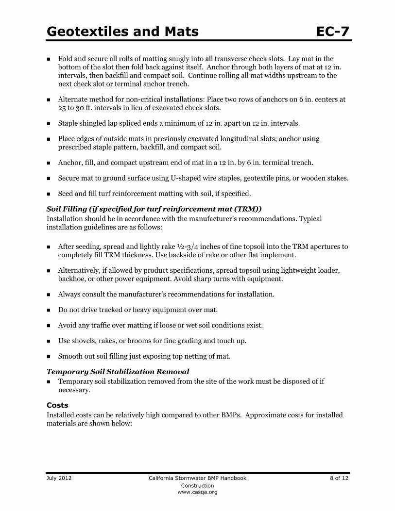
Fold and secure all rolls of matting snugly into all transverse check slots. Lay mat in the bottom of the slot then fold back against itself. Anchor through both layers of mat at 12 in. intervals, then backfill and compact soil. Continue rolling all mat widths upstream to the next check slot or terminal anchor trench.
Alternate method for non-critical installations: Place two rows of anchors on 6 in. centers at 25 to 30 ft. intervals in lieu of excavated check slots.
Staple shingled lap spliced ends a minimum of 12 in. apart on 12 in. intervals.
Place edges of outside mats in previously excavated longitudinal slots; anchor using prescribed staple pattern, backfill, and compact soil.
Anchor, fill, and compact upstream end of mat in a 12 in. by 6 in. terminal trench.
Secure mat to ground surface using U-shaped wire staples, geotextile pins, or wooden stakes.
Seed and fill turf reinforcement matting with soil, if specified.
Soil Filling (if specified for turf reinforcement mat (TRM))
Installation should be in accordance with the manufacturer’s recommendations. Typical installation guidelines are as follows:
After seeding, spread and lightly rake ½-3/4 inches of fine topsoil into the TRM apertures to completely fill TRM thickness. Use backside of rake or other flat implement.
Alternatively, if allowed by product specifications, spread topsoil using lightweight loader, backhoe, or other power equipment. Avoid sharp turns with equipment.
Always consult the manufacturer's recommendations for installation.
Do not drive tracked or heavy equipment over mat.
Avoid any traffic over matting if loose or wet soil conditions exist.
Use shovels, rakes, or brooms for fine grading and touch up.
Smooth out soil filling just exposing top netting of mat.
Temporary Soil Stabilization Removal
Temporary soil stabilization removed from the site of the work must be disposed of if necessary.
Costs
Installed costs can be relatively high compared to other BMPs. Approximate costs for installed materials are shown below:

Geotextiles and Mats EC-7
July 2012 California Stormwater BMP Handbook 9 of 12
Construction
www.casqa.org
Rolled Erosion Control Products Installed Cost per
Acre (2004)1
Estimated Cost per Acre (2009)2
Biodegradable
Jute Mesh $6,000-$7,000 $6,600-$7,700
Curled Wood Fiber $8,000-$10,500 $8,800-$11,050
Straw $8,000-$10,500 $8,800-$11,050
Wood Fiber $8,000-$10,500 $8,800-$11,050
Coconut Fiber $13,000-$14,000 $14,300-$15,400
Coconut Fiber Mesh $30,000-$33,000 $33,000-$36,300
Straw Coconut Fiber $10,000-$12,000 $11,000-$13,200
Non-Biodegradable
Plastic Netting $2,000-$2,200 $2,200-$2,220
Plastic Mesh $3,000-$3,500 $3,300-$3,850
Synthetic Fiber with Netting $34,000-$40,000 $37,400-$44,000
Bonded Synthetic Fibers $45,000-$55,000 $49,500-$60,500
Combination with Biodegradable $30,000-$36,000 $33,000-$39,600
1. Source: Cost information received from individual product manufacturers solicited by Geosyntec Consultants (2004).
2. 2009 costs reflect a 10% escalation over year 2004 costs. Escalation based on informal survey of industry trends. Note: Expected cost increase is offset by competitive economic conditions.
Inspection and Maintenance
RECPs must be inspected in accordance with General Permit requirements for the associated project type and risk level. It is recommended that at a minimum, BMPs be inspected weekly, prior to forecasted rain events, daily during extended rain events, and after the conclusion of rain events.
Areas where erosion is evident shall be repaired and BMPs reapplied as soon as possible. Care should be exercised to minimize the damage to protected areas while making repairs, as any area damaged will require reapplication of BMPs.
If washout or breakage occurs, re-install the material after repairing the damage to the slope or channel.
Make sure matting is uniformly in contact with the soil.
Check that all the lap joints are secure.
Check that staples are flush with the ground.
References
Erosion and Sediment Control Manual, Oregon Department of Environmental Quality, February 2005
Erosion Control Pilot Study Report, State of California Department of Transportation (Caltrans), June 2000.
Guides for Erosion and Sediment Controls in California, USDA Soils Conservation Service, January 1991.

Geotextiles and Mats EC-7
July 2012 California Stormwater BMP Handbook 10 of 12
Construction
www.casqa.org
National Management Measures to Control Nonpoint Source Pollution from Urban Areas, United States Environmental Protection Agency, 2002.
Stormwater Quality Handbooks Construction Site Best Management Practices (BMPs) Manual, State of California Department of Transportation (Caltrans), March 2003.
Guidance Document: Soil Stabilization for Temporary Slopes, State of California Department of Transportation (Caltrans), November 1999.
Stormwater Management of the Puget Sound Basin, Technical Manual, Publication #91-75, Washington State Department of Ecology, February 1992.
Water Quality Management Plan for The Lake Tahoe Region, Volume II, Handbook of Management Practices, Tahoe Regional Planning Agency, November 1988.

Geotextiles and Mats EC-7
July 2012 California Stormwater BMP Handbook 11 of 12
Construction
www.casqa.org

Geotextiles and Mats EC-7
July 2012 California Stormwater BMP Handbook 12 of 12
Construction
www.casqa.org

Check Dams SE-4
July 2012 California Stormwater BMP Handbook Portal 1 of 7
Construction
www.casqa.org
Description and Purpose
A check dam is a small barrier constructed of rock, gravel bags, sandbags, fiber rolls, or other proprietary products, placed across a constructed swale or drainage ditch. Check dams reduce the effective slope of the channel, thereby reducing scour and channel erosion by reducing flow velocity and increasing residence time within the channel, allowing sediment to settle.
Suitable Applications
Check dams may be appropriate in the following situations:
To promote sedimentation behind the dam.
To prevent erosion by reducing the velocity of channel flow in small intermittent channels and temporary swales.
In small open channels that drain 10 acres or less.
In steep channels where stormwater runoff velocities exceed 5 ft/s.
During the establishment of grass linings in drainage ditches or channels.
In temporary ditches where the short length of service does not warrant establishment of erosion-resistant linings.
To act as a grade control structure.
Categories
EC Erosion Control
SE Sediment Control
TC Tracking Control
WE Wind Erosion Control
NS Non-Stormwater Management Control
WM Waste Management and Materials Pollution Control
Legend:
Primary Category
Secondary Category
Targeted Constituents
Sediment
Nutrients
Trash
Metals
Bacteria
Oil and Grease
Organics
Potential Alternatives
SE-5 Fiber Rolls
SE-6 Gravel Bag Berm
SE-8 Sandbag Barrier
SE-12 Manufactured Linear Sediment Controls
SE-14 Biofilter Bags
If User/Subscriber modifies this fact sheet in any way, the CASQA name/logo and footer below must be removed from each page and not appear on the modified version.

Check Dams SE-4
July 2012 California Stormwater BMP Handbook Portal 2 of 7
Construction
www.casqa.org
Limitations
Not to be used in live streams or in channels with extended base flows.
Not appropriate in channels that drain areas greater than 10 acres.
Not appropriate in channels that are already grass-lined unless erosion potential or sediment-laden flow is expected, as installation may damage vegetation.
Require extensive maintenance following high velocity flows.
Promotes sediment trapping which can be re-suspended during subsequent storms or removal of the check dam.
Do not construct check dams with straw bales or silt fence.
Water suitable for mosquito production may stand behind check dams, particularly if subjected to daily non-stormwater discharges.
Implementation
General
Check dams reduce the effective slope and create small pools in swales and ditches that drain 10 acres or less. Using check dams to reduce channel slope reduces the velocity of stormwater flows, thus reducing erosion of the swale or ditch and promoting sedimentation. Thus, check dams are dual-purpose and serve an important role as erosion controls as well as as sediment controls. Note that use of 1-2 isolated check dams for sedimentation will likely result in little net removal of sediment because of the small detention time and probable scour during longer storms. Using a series of check dams will generally increase their effectiveness. A sediment trap (SE-3) may be placed immediately upstream of the check dam to increase sediment removal efficiency.
Design and Layout
Check dams work by decreasing the effective slope in ditches and swales. An important consequence of the reduced slope is a reduction in capacity of the ditch or swale. This reduction in capacity should be considered when using this BMP, as reduced capacity can result in overtopping of the ditch or swale and resultant consequences. In some cases, such as a “permanent” ditch or swale being constructed early and used as a “temporary” conveyance for construction flows, the ditch or swale may have sufficient capacity such that the temporary reduction in capacity due to check dams is acceptable. When check dams reduce capacities beyond acceptable limits, either:
Don’t use check dams. Consider alternative BMPs, or.
Increase the size of the ditch or swale to restore capacity.
Maximum slope and velocity reduction is achieved when the toe of the upstream dam is at the same elevation as the top of the downstream dam (see “Spacing Between Check Dams” detail at the end of this fact sheet). The center section of the dam should be lower than the edge sections (at least 6 inches), acting as a spillway, so that the check dam will direct flows to the center of

Check Dams SE-4
July 2012 California Stormwater BMP Handbook Portal 3 of 7
Construction
www.casqa.org
the ditch or swale (see “Typical Rock Check Dam” detail at the end of this fact sheet). Bypass or side-cutting can occur if a sufficient spillway is not provided in the center of the dam.
Check dams are usually constructed of rock, gravel bags, sandbags, and fiber rolls. A number of products can also be used as check dams (e.g. HDPE check dams, temporary silt dikes (SE-12)), and some of these products can be removed and reused. Check dams can also be constructed of logs or lumber, and have the advantage of a longer lifespan when compared to gravel bags, sandbags, and fiber rolls. Check dams should not be constructed from straw bales or silt fences, since concentrated flows quickly wash out these materials.
Rock check dams are usually constructed of 8 to 12 in. rock. The rock is placed either by hand or mechanically, but never just dumped into the channel. The dam should completely span the ditch or swale to prevent washout. The rock used should be large enough to stay in place given the expected design flow through the channel. It is recommended that abutments be extended 18 in. into the channel bank. Rock can be graded such that smaller diameter rock (e.g. 2-4 in) is located on the upstream side of larger rock (holding the smaller rock in place); increasing residence time.
Log check dams are usually constructed of 4 to 6 in. diameter logs, installed vertically. The logs should be embedded into the soil at least 18 in. Logs can be bolted or wired to vertical support logs that have been driven or buried into the soil.
See fiber rolls, SE-5, for installation of fiber roll check dams.
Gravel bag and sand bag check dams are constructed by stacking bags across the ditch or swale, shaped as shown in the drawings at the end of this fact sheet (see “Gravel Bag Check Dam” detail at the end of this fact sheet).
Manufactured products, such as temporary silt dikes (SE-12), should be installed in accordance with the manufacturer’s instructions. Installation typically requires anchoring or trenching of products, as well as regular maintenance to remove accumulated sediment and debris.
If grass is planted to stabilize the ditch or swale, the check dam should be removed when the grass has matured (unless the slope of the swales is greater than 4%).
The following guidance should be followed for the design and layout of check dams:
Install the first check dam approximately 16 ft from the outfall device and at regular intervals based on slope gradient and soil type.
Check dams should be placed at a distance and height to allow small pools to form between each check dam.
For multiple check dam installation, backwater from a downstream check dam should reach the toes of the upstream check dam.
A sediment trap provided immediately upstream of the check dam will help capture sediment. Due to the potential for this sediment to be resuspended in subsequent storms, the sediment trap should be cleaned following each storm event.

Check Dams SE-4
July 2012 California Stormwater BMP Handbook Portal 4 of 7
Construction
www.casqa.org
High flows (typically a 2-year storm or larger) should safely flow over the check dam without an increase in upstream flooding or damage to the check dam.
Where grass is used to line ditches, check dams should be removed when grass has matured sufficiently to protect the ditch or swale.
Materials
Rock used for check dams should typically be 8-12 in rock and be sufficiently sized to stay in place given expected design flows in the channel. Smaller diameter rock (e.g. 2 to 4 in) can be placed on the upstream side of larger rock to increase residence time.
Gravel bags used for check dams should conform to the requirements of SE-6, Gravel Bag Berms.
Sandbags used for check dams should conform to SE-8, Sandbag Barrier.
Fiber rolls used for check dams should conform to SE-5, Fiber Rolls.
Temporary silt dikes used for check dams should conform to SE-12, Temporary Silt Dikes.
Installation
Rock should be placed individually by hand or by mechanical methods (no dumping of rock) to achieve complete ditch or swale coverage.
Tightly abut bags and stack according to detail shown in the figure at the end of this section (pyramid approach). Gravel bags and sandbags should not be stacked any higher than 3 ft.
Upper rows or gravel and sand bags shall overlap joints in lower rows.
Fiber rolls should be trenched in, backfilled, and firmly staked in place.
Install along a level contour.
HDPE check dams, temporary silt dikes, and other manufactured products should be used and installed per manufacturer specifications.
Costs
Cost consists of labor costs if materials are readily available (such as gravel on-site). If material must be imported, costs will increase. For other material and installation costs, see SE-5, SE-6, SE-8, SE-12, and SE-14.
Inspection and Maintenance
BMPs must be inspected in accordance with General Permit requirements for the associated project type and risk level. It is recommended that at a minimum, BMPs be inspected weekly, prior to forecasted rain events, daily during extended rain events, and after the conclusion of rain events.
Replace missing rock, bags, rolls, etc. Replace bags or rolls that have degraded or have become damaged.

Check Dams SE-4
July 2012 California Stormwater BMP Handbook Portal 5 of 7
Construction
www.casqa.org
If the check dam is used as a sediment capture device, sediment that accumulates behind the BMP should be periodically removed in order to maintain BMP effectiveness. Sediment should be removed when the sediment accumulation reaches one-third of the barrier height.
If the check dam is used as a grade control structure, sediment removal is not required as long as the system continues to control the grade.
Inspect areas behind check dams for pools of standing water, especially if subjected to daily non-stormwater discharges.
Remove accumulated sediment prior to permanent seeding or soil stabilization.
Remove check dam and accumulated sediment when check dams are no longer needed.
References
Draft – Sedimentation and Erosion Control, and Inventory of Current Practices, USEPA, April 1990.
Manual of Standards of Erosion and Sediment Control Measures, Association of Bay Area Governments, May 1995.
Stormwater Quality Handbooks - Construction Site Best Management Practices (BMPs) Manual, State of California Department of Transportation (Caltrans), March 2003.
Stormwater Management of the Puget Sound Basin, Technical Manual, Publication #91-75, Washington State Department of Ecology, February 1992.
Erosion and Sediment Control Manual, Oregon Department of Environmental Quality, February 2005.
Metzger, M.E. 2004. Managing mosquitoes in stormwater treatment devices. University of California Division of Agriculture and Natural Resources, Publication 8125. On-line: http:// anrcatalog.ucdavis.edu/pdf/8125.pdf

Check Dams SE-4
July 2012 California Stormwater BMP Handbook Portal 6 of 7
Construction
www.casqa.org

Check Dams SE-4
July 2012 California Stormwater BMP Handbook Portal 7 of 7
Construction
www.casqa.org

Fiber Rolls SE-5
July 2012 California Stormwater BMP Handbook Portal 1 of 5 Construction www.casqa.org
Description and Purpose A fiber roll consists of straw, coir, or other biodegradable materials bound into a tight tubular roll wrapped by netting, which can be photodegradable or natural. Additionally, gravel core fiber rolls are available, which contain an imbedded ballast material such as gravel or sand for additional weight when staking the rolls are not feasible (such as use as inlet protection). When fiber rolls are placed at the toe and on the face of slopes along the contours, they intercept runoff, reduce its flow velocity, release the runoff as sheet flow, and provide removal of sediment from the runoff (through sedimentation). By interrupting the length of a slope, fiber rolls can also reduce sheet and rill erosion until vegetation is established.
Suitable Applications Fiber rolls may be suitable:
Along the toe, top, face, and at grade breaks of exposed and erodible slopes to shorten slope length and spread runoff as sheet flow.
At the end of a downward slope where it transitions to a steeper slope.
Along the perimeter of a project.
As check dams in unlined ditches with minimal grade.
Down-slope of exposed soil areas.
At operational storm drains as a form of inlet protection.
Categories
EC Erosion Control
SE Sediment Control
TC Tracking Control
WE Wind Erosion Control
NS Non-Stormwater Management Control
WM Waste Management and Materials Pollution Control
Legend:
Primary Category
Secondary Category
Targeted Constituents
Sediment Nutrients Trash Metals Bacteria Oil and Grease Organics
Potential Alternatives
SE-1 Silt Fence
SE-6 Gravel Bag Berm
SE-8 Sandbag Barrier
SE-12 Manufactured Linear Sediment Controls
SE-14 Biofilter Bags
If User/Subscriber modifies this fact sheet in any way, the CASQA name/logo and footer below must be removed from each page and not appear on the modified version.

Fiber Rolls SE-5
July 2012 California Stormwater BMP Handbook Portal 2 of 5 Construction www.casqa.org
Around temporary stockpiles.
Limitations Fiber rolls are not effective unless trenched in and staked.
Not intended for use in high flow situations.
Difficult to move once saturated.
If not properly staked and trenched in, fiber rolls could be transported by high flows.
Fiber rolls have a very limited sediment capture zone.
Fiber rolls should not be used on slopes subject to creep, slumping, or landslide.
Rolls typically function for 12-24 months depending upon local conditions.
Implementation Fiber Roll Materials Fiber rolls should be prefabricated.
Fiber rolls may come manufactured containing polyacrylamide (PAM), a flocculating agent within the roll. Fiber rolls impregnated with PAM provide additional sediment removal capabilities and should be used in areas with fine, clayey or silty soils to provide additional sediment removal capabilities. Monitoring may be required for these installations.
Fiber rolls are made from weed free rice straw, flax, or a similar agricultural material bound into a tight tubular roll by netting.
Typical fiber rolls vary in diameter from 9 in. to 20 in. Larger diameter rolls are available as well.
Installation Locate fiber rolls on level contours spaced as follows:
Slope inclination of 4:1 (H:V) or flatter: Fiber rolls should be placed at a maximum interval of 20 ft.
Slope inclination between 4:1 and 2:1 (H:V): Fiber Rolls should be placed at a maximum interval of 15 ft. (a closer spacing is more effective).
Slope inclination 2:1 (H:V) or greater: Fiber Rolls should be placed at a maximum interval of 10 ft. (a closer spacing is more effective).
Prepare the slope before beginning installation.
Dig small trenches across the slope on the contour. The trench depth should be ¼ to 1/3 of the thickness of the roll, and the width should equal the roll diameter, in order to provide area to backfill the trench.
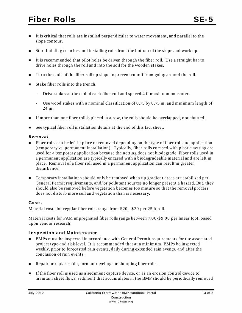
Fiber Rolls SE-5
July 2012 California Stormwater BMP Handbook Portal 3 of 5 Construction www.casqa.org
It is critical that rolls are installed perpendicular to water movement, and parallel to the slope contour.
Start building trenches and installing rolls from the bottom of the slope and work up.
It is recommended that pilot holes be driven through the fiber roll. Use a straight bar to drive holes through the roll and into the soil for the wooden stakes.
Turn the ends of the fiber roll up slope to prevent runoff from going around the roll.
Stake fiber rolls into the trench.
Drive stakes at the end of each fiber roll and spaced 4 ft maximum on center.
Use wood stakes with a nominal classification of 0.75 by 0.75 in. and minimum length of 24 in.
If more than one fiber roll is placed in a row, the rolls should be overlapped, not abutted.
See typical fiber roll installation details at the end of this fact sheet.
Removal Fiber rolls can be left in place or removed depending on the type of fiber roll and application
(temporary vs. permanent installation). Typically, fiber rolls encased with plastic netting are used for a temporary application because the netting does not biodegrade. Fiber rolls used in a permanent application are typically encased with a biodegradeable material and are left in place. Removal of a fiber roll used in a permanent application can result in greater disturbance.
Temporary installations should only be removed when up gradient areas are stabilized per General Permit requirements, and/or pollutant sources no longer present a hazard. But, they should also be removed before vegetation becomes too mature so that the removal process does not disturb more soil and vegetation than is necessary.
Costs Material costs for regular fiber rolls range from $20 - $30 per 25 ft roll.
Material costs for PAM impregnated fiber rolls range between 7.00-$9.00 per linear foot, based upon vendor research.
Inspection and Maintenance BMPs must be inspected in accordance with General Permit requirements for the associated
project type and risk level. It is recommended that at a minimum, BMPs be inspected weekly, prior to forecasted rain events, daily during extended rain events, and after the conclusion of rain events.
Repair or replace split, torn, unraveling, or slumping fiber rolls.
If the fiber roll is used as a sediment capture device, or as an erosion control device to maintain sheet flows, sediment that accumulates in the BMP should be periodically removed

Fiber Rolls SE-5
July 2012 California Stormwater BMP Handbook Portal 4 of 5 Construction www.casqa.org
in order to maintain BMP effectiveness. Sediment should be removed when sediment accumulation reaches one-third the designated sediment storage depth.
If fiber rolls are used for erosion control, such as in a check dam, sediment removal should not be required as long as the system continues to control the grade. Sediment control BMPs will likely be required in conjunction with this type of application.
Repair any rills or gullies promptly.
References Stormwater Quality Handbooks - Construction Site Best Management Practices (BMPs) Manual, State of California Department of Transportation (Caltrans), March 2003.
Erosion and Sediment Control Manual, Oregon Department of Environmental Quality, February 2005.

Fiber Rolls SE-5
July 2012 California Stormwater BMP Handbook Portal 5 of 5 Construction www.casqa.org

Stabilized Construction Roadway TC-2
January 2011 California Stormwater BMP Handbook 1 of 4 Construction www.casqa.org
Description and Purpose Access roads, subdivision roads, parking areas, and other onsite vehicle transportation routes should be stabilized immediately after grading, and frequently maintained to prevent erosion and control dust.
Suitable Applications This BMP should be applied for the following conditions:
Temporary Construction Traffic:
Phased construction projects and offsite road access
Construction during wet weather
Construction roadways and detour roads:
Where mud tracking is a problem during wet weather
Where dust is a problem during dry weather
Adjacent to water bodies
Where poor soils are encountered
Limitations The roadway must be removed or paved when construction
is complete.
Categories
EC Erosion Control
SE Sediment Control
TC Tracking Control
WE Wind Erosion Control
NS Non-Stormwater Management Control
WM Waste Management and Materials Pollution Control
Legend:
Primary Objective
Secondary Objective
Targeted Constituents
Sediment Nutrients Trash Metals Bacteria Oil and Grease Organics
Potential Alternatives
None
If User/Subscriber modifies this fact sheet in any way, the CASQA name/logo and footer below must be removed from each page and not appear on the modified version.

Stabilized Construction Roadway TC-2
January 2011 California Stormwater BMP Handbook 2 of 4 Construction www.casqa.org
Certain chemical stabilization methods may cause stormwater or soil pollution and should not be used. See WE-1, Wind Erosion Control.
Management of construction traffic is subject to air quality control measures. Contact the local air quality management agency.
Materials will likely need to be removed prior to final project grading and stabilization.
Use of this BMP may not be applicable to very short duration projects.
Implementation General Areas that are graded for construction vehicle transport and parking purposes are especially susceptible to erosion and dust. The exposed soil surface is continually disturbed, leaving no opportunity for vegetative stabilization. Such areas also tend to collect and transport runoff waters along their surfaces. During wet weather, they often become muddy quagmires that generate significant quantities of sediment that may pollute nearby streams or be transported offsite on the wheels of construction vehicles. Dirt roads can become so unstable during wet weather that they are virtually unusable.
Efficient construction road stabilization not only reduces onsite erosion but also can significantly speed onsite work, avoid instances of immobilized machinery and delivery vehicles, and generally improve site efficiency and working conditions during adverse weather
Installation/Application Criteria Permanent roads and parking areas should be paved as soon as possible after grading. As an alternative where construction will be phased, the early application of gravel or chemical stabilization may solve potential erosion and stability problems. Temporary gravel roadway should be considered during the rainy season and on slopes greater than 5%.
Temporary roads should follow the contour of the natural terrain to the maximum extent possible. Slope should not exceed 15%. Roadways should be carefully graded to drain transversely. Provide drainage swales on each side of the roadway in the case of a crowned section or one side in the case of a super elevated section. Simple gravel berms without a trench can also be used.
Installed inlets should be protected to prevent sediment laden water from entering the storm sewer system (SE-10, Storm Drain Inlet Protection). In addition, the following criteria should be considered.
Road should follow topographic contours to reduce erosion of the roadway.
The roadway slope should not exceed 15%.
Chemical stabilizers or water are usually required on gravel or dirt roads to prevent dust (WE-1, Wind Erosion Control).
Properly grade roadway to prevent runoff from leaving the construction site.
Design stabilized access to support heaviest vehicles and equipment that will use it.

Stabilized Construction Roadway TC-2
January 2011 California Stormwater BMP Handbook 3 of 4 Construction www.casqa.org
Stabilize roadway using aggregate, asphalt concrete, or concrete based on longevity, required performance, and site conditions. The use of cold mix asphalt or asphalt concrete (AC) grindings for stabilized construction roadway is not allowed.
Coordinate materials with those used for stabilized construction entrance/exit points.
If aggregate is selected, place crushed aggregate over geotextile fabric to at least 12 in. depth. A crushed aggregate greater than 3 in. but smaller than 6 in. should be used.
Inspection and Maintenance Inspect and verify that activity–based BMPs are in place prior to the commencement of
associated activities. While activities associated with the BMP are under way, inspect BMPs in accordance with General Permit requirements for the associated project type and risk level. It is recommended that at a minimum, BMPs be inspected weekly, prior to forecasted rain events, daily during extended rain events, and after the conclusion of rain events.
Keep all temporary roadway ditches clear.
When no longer required, remove stabilized construction roadway and re-grade and repair slopes.
Periodically apply additional aggregate on gravel roads.
Active dirt construction roads are commonly watered three or more times per day during the dry season.
Costs Gravel construction roads are moderately expensive, but cost is often balanced by reductions in construction delay. No additional costs for dust control on construction roads should be required above that needed to meet local air quality requirements.
References Blueprint for a Clean Bay: Best Management Practices to Prevent Stormwater Pollution from Construction Related Activities; Santa Clara Valley Nonpoint Source Pollution Control Program, 1995.
Coastal Nonpoint Pollution Control Program; Program Development and Approval Guidance, Working Group, Working Paper; USEPA, April 1992.
Manual of Standards of Erosion and Sediment Control Measures, Association of Bay Area Governments, May 1995.
Stormwater Quality Handbooks Construction Site Best Management Practices (BMPs) Manual, State of California Department of Transportation (Caltrans), November 2000.
Stormwater Management for Construction Activities, Developing Pollution Prevention Plans and Best Management Practices, EPA 832-R-92005; USEPA, April 1992.
Stormwater Management of the Puget Sound Basin, Technical Manual, Publication #91-75, Washington State Department of Ecology, February 1992.

Stabilized Construction Roadway TC-2
January 2011 California Stormwater BMP Handbook 4 of 4 Construction www.casqa.org
Virginia Erosion and Sedimentation Control Handbook, Virginia Department of Conservation and Recreation, Division of Soil and Water Conservation, 1991.
Water Quality Management Plan for the Lake Tahoe Region, Volume II, Handbook of Management Practices, Tahoe Regional Planning Agency, November 1988.

Wind Erosion Control WE-1
May 2011 California Stormwater BMP Handbook 1 of 5 Construction www.casqa.org
Description and Purpose Wind erosion or dust control consists of applying water or other chemical dust suppressants as necessary to prevent or alleviate dust nuisance generated by construction activities. Covering small stockpiles or areas is an alternative to applying water or other dust palliatives.
California’s Mediterranean climate, with a short “wet” season and a typically long, hot “dry” season, allows the soils to thoroughly dry out. During the dry season, construction activities are at their peak, and disturbed and exposed areas are increasingly subject to wind erosion, sediment tracking and dust generated by construction equipment. Site conditions and climate can make dust control more of an erosion problem than water based erosion. Additionally, many local agencies, including Air Quality Management Districts, require dust control and/or dust control permits in order to comply with local nuisance laws, opacity laws (visibility impairment) and the requirements of the Clean Air Act. Wind erosion control is required to be implemented at all construction sites greater than 1 acre by the General Permit.
Suitable Applications Most BMPs that provide protection against water-based erosion will also protect against wind-based erosion and dust control requirements required by other agencies will generally meet wind erosion control requirements for water quality protection. Wind erosion control BMPs are suitable during the following construction activities:
Categories
EC Erosion Control
SE Sediment Control
TC Tracking Control
WE Wind Erosion Control
NS Non-Stormwater Management Control
WM Waste Management and Materials Pollution Control
Legend:
Primary Category
Secondary Category
Targeted Constituents
Sediment Nutrients Trash Metals Bacteria Oil and Grease Organics
Potential Alternatives
EC-5 Soil Binders
If User/Subscriber modifies this fact sheet in any way, the CASQA name/logo and footer below must be removed from each page and not appear on the modified version.

Wind Erosion Control WE-1
May 2011 California Stormwater BMP Handbook 2 of 5 Construction www.casqa.org
Construction vehicle traffic on unpaved roads
Drilling and blasting activities
Soils and debris storage piles
Batch drop from front-end loaders
Areas with unstabilized soil
Final grading/site stabilization
Limitations Watering prevents dust only for a short period (generally less than a few hours) and should
be applied daily (or more often) to be effective.
Over watering may cause erosion and track-out.
Oil or oil-treated subgrade should not be used for dust control because the oil may migrate into drainageways and/or seep into the soil.
Chemical dust suppression agents may have potential environmental impacts. Selected chemical dust control agents should be environmentally benign.
Effectiveness of controls depends on soil, temperature, humidity, wind velocity and traffic.
Chemical dust suppression agents should not be used within 100 feet of wetlands or water bodies.
Chemically treated subgrades may make the soil water repellant, interfering with long-term infiltration and the vegetation/re-vegetation of the site. Some chemical dust suppressants may be subject to freezing and may contain solvents and should be handled properly.
In compacted areas, watering and other liquid dust control measures may wash sediment or other constituents into the drainage system.
If the soil surface has minimal natural moisture, the affected area may need to be pre-wetted so that chemical dust control agents can uniformly penetrate the soil surface.
Implementation Dust Control Practices Dust control BMPs generally stabilize exposed surfaces and minimize activities that suspend or track dust particles. The following table presents dust control practices that can be applied to varying site conditions that could potentially cause dust. For heavily traveled and disturbed areas, wet suppression (watering), chemical dust suppression, gravel asphalt surfacing, temporary gravel construction entrances, equipment wash-out areas, and haul truck covers can be employed as dust control applications. Permanent or temporary vegetation and mulching can be employed for areas of occasional or no construction traffic. Preventive measures include minimizing surface areas to be disturbed, limiting onsite vehicle traffic to 15 mph or less, and controlling the number and activity of vehicles on a site at any given time.

Wind Erosion Control WE-1
May 2011 California Stormwater BMP Handbook 3 of 5 Construction www.casqa.org
Chemical dust suppressants include: mulch and fiber based dust palliatives (e.g. paper mulch with gypsum binder), salts and brines (e.g. calcium chloride, magnesium chloride), non-petroleum based organics (e.g. vegetable oil, lignosulfonate), petroleum based organics (e.g. asphalt emulsion, dust oils, petroleum resins), synthetic polymers (e.g. polyvinyl acetate, vinyls, acrylic), clay additives (e.g. bentonite, montimorillonite) and electrochemical products (e.g. enzymes, ionic products).
Site Condition
Dust Control Practices
Permanent Vegetation Mulching
Wet Suppression (Watering)
Chemical Dust
Suppression
Gravel or
Asphalt
Temporary Gravel Construction
Entrances/Equipment Wash Down
Synthetic Covers
Minimize Extent of
Disturbed Area
Disturbed Areas not Subject to
Traffic
X X X X X X
Disturbed Areas
Subject to Traffic
X X X X X
Material Stockpiles X X X X X
Demolition X X X
Clearing/ Excavation X X X
Truck Traffic on Unpaved
Roads
X X X X X
Tracking X X
Additional preventive measures include:
Schedule construction activities to minimize exposed area (see EC-1, Scheduling).
Quickly treat exposed soils using water, mulching, chemical dust suppressants, or stone/gravel layering.
Identify and stabilize key access points prior to commencement of construction.
Minimize the impact of dust by anticipating the direction of prevailing winds.
Restrict construction traffic to stabilized roadways within the project site, as practicable.
Water should be applied by means of pressure-type distributors or pipelines equipped with a spray system or hoses and nozzles that will ensure even distribution.
All distribution equipment should be equipped with a positive means of shutoff.
Unless water is applied by means of pipelines, at least one mobile unit should be available at all times to apply water or dust palliative to the project.
If reclaimed waste water is used, the sources and discharge must meet California Department of Health Services water reclamation criteria and the Regional Water Quality

Wind Erosion Control WE-1
May 2011 California Stormwater BMP Handbook 4 of 5 Construction www.casqa.org
Control Board (RWQCB) requirements. Non-potable water should not be conveyed in tanks or drain pipes that will be used to convey potable water and there should be no connection between potable and non-potable supplies. Non-potable tanks, pipes, and other conveyances should be marked, “NON-POTABLE WATER - DO NOT DRINK.”
Pave or chemically stabilize access points where unpaved traffic surfaces adjoin paved roads.
Provide covers for haul trucks transporting materials that contribute to dust.
Provide for rapid clean up of sediments deposited on paved roads. Furnish stabilized construction road entrances and wheel wash areas.
Stabilize inactive areas of construction sites using temporary vegetation or chemical stabilization methods.
For chemical stabilization, there are many products available for chemically stabilizing gravel roadways and stockpiles. If chemical stabilization is used, the chemicals should not create any adverse effects on stormwater, plant life, or groundwater and should meet all applicable regulatory requirements.
Costs Installation costs for water and chemical dust suppression vary based on the method used and the length of effectiveness. Annual costs may be high since some of these measures are effective for only a few hours to a few days.
Inspection and Maintenance Inspect and verify that activity-based BMPs are in place prior to the commencement of
associated activities.
BMPs must be inspected in accordance with General Permit requirements for the associated project type and risk level. It is recommended that at a minimum, BMPs be inspected weekly, prior to forecasted rain events, daily during extended rain events, and after the conclusion of rain events.
Check areas protected to ensure coverage.
Most water-based dust control measures require frequent application, often daily or even multiple times per day. Obtain vendor or independent information on longevity of chemical dust suppressants.
References Best Management Practices and Erosion Control Manual for Construction Sites, Flood Control District of Maricopa County, Arizona, September 1992.
California Air Pollution Control Laws, California Air Resources Board, updated annually.
Construction Manual, Chapter 4, Section 10, “Dust Control”; Section 17, “Watering”; and Section 18, “Dust Palliative”, California Department of Transportation (Caltrans), July 2001.

Wind Erosion Control WE-1
May 2011 California Stormwater BMP Handbook 5 of 5 Construction www.casqa.org
Prospects for Attaining the State Ambient Air Quality Standards for Suspended Particulate Matter (PM10), Visibility Reducing Particles, Sulfates, Lead, and Hydrogen Sulfide, California Air Resources Board, April 1991.
Stormwater Quality Handbooks Construction Site Best Management Practices (BMPs) Manual, State of California Department of Transportation (Caltrans), March 2003.

Water Conservation Practices NS-1
January 2011 California Stormwater BMP Handbook 1 of 2 Construction www.casqa.org
Description and Purpose Water conservation practices are activities that use water during the construction of a project in a manner that avoids causing erosion and the transport of pollutants offsite. These practices can reduce or eliminate non-stormwater discharges.
Suitable Applications Water conservation practices are suitable for all construction sites where water is used, including piped water, metered water, trucked water, and water from a reservoir.
Limitations None identified.
Implementation Keep water equipment in good working condition.
Stabilize water truck filling area.
Repair water leaks promptly.
Washing of vehicles and equipment on the construction site is discouraged.
Avoid using water to clean construction areas. If water must be used for cleaning or surface preparation, surface should be swept and vacuumed first to remove dirt. This will minimize amount of water required.
Categories
EC Erosion Control
SE Sediment Control
TC Tracking Control
WE Wind Erosion Control
NS Non-Stormwater Management Control
WM Waste Management and Materials Pollution Control
Legend:
Primary Objective
Secondary Objective
Targeted Constituents
Sediment Nutrients Trash Metals Bacteria Oil and Grease Organics
Potential Alternatives
None
If User/Subscriber modifies this fact sheet in any way, the CASQA name/logo and footer below must be removed from each page and not appear on the modified version.

Water Conservation Practices NS-1
January 2011 California Stormwater BMP Handbook 2 of 2 Construction www.casqa.org
Direct construction water runoff to areas where it can soak into the ground or be collected and reused.
Authorized non-stormwater discharges to the storm drain system, channels, or receiving waters are acceptable with the implementation of appropriate BMPs.
Lock water tank valves to prevent unauthorized use.
Costs The cost is small to none compared to the benefits of conserving water.
Inspection and Maintenance Inspect and verify that activity based BMPs are in place prior to the commencement of
authorized non-stormwater discharges.
Inspect BMPs in accordance with General Permit requirements for the associated project type and risk level. It is recommended that at a minimum, BMPs be inspected weekly, prior to forecasted rain events, daily during extended rain events, and after the conclusion of rain events.
Inspect BMPs subject to non-stormwater discharges daily while non-stormwater discharges are occuring.
Repair water equipment as needed to prevent unintended discharges.
Water trucks
Water reservoirs (water buffalos)
Irrigation systems
Hydrant connections
References Stormwater Quality Handbooks - Construction Site Best Management Practices (BMPs) Manual, State of California Department of Transportation (Caltrans), November 2000.

Temporary Stream Crossing NS-4
January 2011 California Stormwater BMP Handbook 1 of 8
Construction
www.casqa.org
Description and Purpose
A temporary stream crossing is a temporary culvert, ford or bridge placed across a waterway to provide access for construction purposes for a period of less than one year. Temporary access crossings are not intended to maintain traffic for the public. The temporary access will eliminate erosion and downstream sedimentation caused by vehicles.
Suitable Applications
Temporary stream crossings should be installed at all designated crossings of perennial and intermittent streams on the construction site, as well as for dry channels that may be significantly eroded by construction traffic.
Temporary streams crossings are installed at sites:
Where appropriate permits have been secured (404 Permits, and 401 Certifications)
Where construction equipment or vehicles need to frequently cross a waterway
When alternate access routes impose significant constraints
When crossing perennial streams or waterways causes significant erosion
Where construction activities will not last longer than one year
Categories
EC Erosion Control
SE Sediment Control
TC Tracking Control
WE Wind Erosion Control
NS Non-Stormwater Management Control
WM Waste Management and Materials Pollution Control
Legend:
Primary Objective
Secondary Objective
Targeted Constituents
Sediment
Nutrients
Trash
Metals
Bacteria
Oil and Grease
Organics
Potential Alternatives
None
If User/Subscriber modifies this fact sheet in any way, the CASQA name/logo and footer below must be removed from each page and not appear on the modified version.

Temporary Stream Crossing NS-4
January 2011 California Stormwater BMP Handbook 2 of 8
Construction
www.casqa.org
Where appropriate permits have been obtained for the stream crossing
Limitations
The following limitations may apply:
Installation and removal will usually disturb the waterway.
Installation may require Regional Water Quality Control Board (RWQCB) 401 Certification, U.S. Army Corps of Engineers 404 permit and approval by California Department of Fish and Game. If numerical-based water quality standards are mentioned in any of these and other related permits, testing and sampling may be required.
Installation may require dewatering or temporary diversion of the stream. See NS-2, Dewatering Operations and NS-5, Clear Water Diversion.
Installation may cause a constriction in the waterway, which can obstruct flood flow and cause flow backups or washouts. If improperly designed, flow backups can increase the pollutant load through washouts and scouring.
Use of natural or other gravel in the stream for construction of Cellular Confinement System (CCS) ford crossing will be contingent upon approval by fisheries agencies.
Ford crossings may degrade water quality due to contact with vehicles and equipment.
May be expensive for a temporary improvement.
Requires other BMPs to minimize soil disturbance during installation and removal.
Fords should only be used in dry weather.
Implementation
General
The purpose of this BMP is to provide a safe, erosion-free access across a stream for construction equipment. Minimum standards and specifications for the design, construction, maintenance, and removal of the structure should be established by an engineer registered in California. Temporary stream crossings may be necessary to prevent construction equipment from causing erosion of the stream and tracking sediment and other pollutants into the stream.
Temporary stream crossings are used as access points to construction sites when other detour routes may be too long or burdensome for the construction equipment. Often heavy construction equipment must cross streams or creeks, and detour routes may impose too many constraints such as being too narrow or poor soil strength for the equipment loadings. Additionally, the contractor may find a temporary stream crossing more economical for light–duty vehicles to use for frequent crossings, and may have less environmental impact than construction of a temporary access road.
Location of the temporary stream crossing should address:
Site selection where erosion potential is low.

Temporary Stream Crossing NS-4
January 2011 California Stormwater BMP Handbook 3 of 8
Construction
www.casqa.org
Areas where the side slopes from site runoff will not spill into the side slopes of the crossing.
The following types of temporary stream crossings should be considered:
Culverts – A temporary culvert is effective in controlling erosion but will cause erosion during installation and removal. A temporary culvert can be easily constructed and allows for heavy equipment loads.
Fords - Appropriate during the dry season in arid areas. Used on dry washes and ephemeral streams, and low-flow perennial streams. CCS, a type of ford crossing, is also appropriate for use in streams that would benefit from an influx of gravels. A temporary ford provides little sediment and erosion control and is ineffective in controlling erosion in the stream channel. A temporary ford is the least expensive stream crossing and allows for maximum load limits. It also offers very low maintenance. Fords are more appropriate during the dry ice season and in arid areas of California.
Bridges - Appropriate for streams with high flow velocities, steep gradients and where temporary restrictions in the channel are not allowed.
Design
During the long summer construction season in much of California, rainfall is infrequent and many streams are dry. Under these conditions, a temporary ford may be sufficient. A ford is not appropriate if construction will continue through the winter rainy season, if summer thunderstorms are likely, or if the stream flows during most of the year. Temporary culverts and bridges should then be considered and, if used, should be sized to pass a significant design storm (i.e., at least a 10-year storm). The temporary stream crossing should be protected against erosion, both to prevent excessive sedimentation in the stream and to prevent washout of the crossing.
Design and installation requires knowledge of stream flows and soil strength. Designs should be prepared under direction of, and approved by, a registered civil engineer and for bridges, a registered structural engineer. Both hydraulic and construction loading requirements should be considered with the following:
Comply with any special requirements for culvert and bridge crossings, particularly if the temporary stream crossing will remain through the rainy season.
Provide stability in the crossing and adjacent areas to withstand the design flow. The design flow and safety factor should be selected based on careful evaluation of the risks due to over topping, flow backups, or washout.
Install sediment traps immediately downstream of crossings to capture sediments. See SE-3, Sediment Trap.
Avoid oil or other potentially hazardous materials for surface treatment.
Culverts are relatively easy to construct and able to support heavy equipment loads.
Fords are the least expensive of the crossings, with maximum load limits.

Temporary Stream Crossing NS-4
January 2011 California Stormwater BMP Handbook 4 of 8
Construction
www.casqa.org
CCS crossing structures consist of clean, washed gravel and cellular confinement system blocks. CCS are appropriate for streams that would benefit from an influx of gravel; for example, salmonid streams, streams or rivers below reservoirs, and urban, channelized streams. Many urban stream systems are gravel-deprived due to human influences, such as dams, gravel mines, and concrete channels.
CCS allow designers to use either angular or naturally occurring rounded gravel, because the cells provide the necessary structure and stability. In fact, natural gravel is optimal for this technique, because of the habitat improvement it will provide after removal of the CCS.
A gravel depth of 6 to 12 in. for a CCS structure is sufficient to support most construction equipment.
An advantage of a CCS crossing structure is that relatively little rock or gravel is needed, because the CCS provides the stability.
Bridges are generally more expensive to design and construct, but provide the least disturbance of the streambed and constriction of the waterway flows.
Construction and Use
Stabilize construction roadways, adjacent work area, and stream bottom against erosion.
Construct during dry periods to minimize stream disturbance and reduce costs.
Construct at or near the natural elevation of the streambed to prevent potential flooding upstream of the crossing.
Install temporary erosion control BMPs in accordance with erosion control BMP fact sheets to minimize erosion of embankment into flow lines.
Any temporary artificial obstruction placed within flowing water should only be built from material, such as clean gravel or sandbags, that will not introduce sediment or silt into the watercourse.
Temporary water body crossings and encroachments should be constructed to minimize scour. Cobbles used for temporary water body crossings or encroachments should be clean, rounded river cobble.
Vehicles and equipment should not be driven, operated, fueled, cleaned, maintained, or stored in the wet or dry portions of a water body where wetland vegetation, riparian vegetation, or aquatic organisms may be destroyed.
The exterior of vehicles and equipment that will encroach on the water body within the project should be maintained free of grease, oil, fuel, and residues.
Drip pans should be placed under all vehicles and equipment placed on docks, barges, or other structures over water bodies when the vehicle or equipment is planned to be idle for more than one hour.

Temporary Stream Crossing NS-4
January 2011 California Stormwater BMP Handbook 5 of 8
Construction
www.casqa.org
Disturbance or removal of vegetation should not exceed the minimum necessary to complete operations. Precautions should be taken to avoid damage to vegetation by people or equipment. Disturbed vegetation should be replaced with the appropriate soil stabilization measures.
Riparian vegetation, when removed pursuant to the provisions of the work, should be cut off no lower than ground level to promote rapid re-growth. Access roads and work areas built over riparian vegetation should be covered by a sufficient layer of clean river run cobble to prevent damage to the underlying soil and root structure. The cobble must be removed upon completion of project activities.
Conceptual temporary stream crossings are shown in the attached figures.
Costs
Caltrans Construction Cost index for temporary bridge crossings is $45-$95/ft2.
Inspection and Maintenance
Inspect and verify that activity-based BMPs are in place prior to the commencement of associated activities. While activities associated with the BMP are under way, inspect BMPs in accordance with General Permit requirements for the associated project type and risk level. It is recommended that at a minimum, BMPs be inspected weekly, prior to forecasted rain events, daily during extended rain events, and after the conclusion of rain events.
Check for blockage in the channel, sediment buildup or trapped debris in culverts, blockage behind fords or under bridges.
Check for erosion of abutments, channel scour, riprap displacement, or piping in the soil.
Check for structural weakening of the temporary crossings, such as cracks, and undermining of foundations and abutments.
Remove sediment that collects behind fords, in culverts, and under bridges periodically.
Replace lost or displaced aggregate from inlets and outlets of culverts and cellular confinement systems.
Remove temporary crossing promptly when it is no longer needed.
References
California Bank and Shore Rock Slope Protection Design – Practitioners Guide and Field Evaluations of Riprap Methods, Caltrans Study No. F90TL03, October 2000.
Stormwater Quality Handbooks - Construction Site Best Management Practices (BMPs) Manual, State of California Department of Transportation (Caltrans), November 2000.

Temporary Stream Crossing NS-4
January 2011 California Stormwater BMP Handbook 6 of 8
Construction
www.casqa.org

Temporary Stream Crossing NS-4
January 2011 California Stormwater BMP Handbook 7 of 8
Construction
www.casqa.org

Temporary Stream Crossing NS-4
January 2011 California Stormwater BMP Handbook 8 of 8
Construction
www.casqa.org

Clear Water Diversion NS-5
August 2011 California Stormwater BMP Handbook 1 of 10 Construction www.casqa.org
Description and Purpose Clear water diversion consists of a system of structures and measures that intercept clear surface water runoff upstream of a project, transport it around the work area, and discharge it downstream with minimal water quality degradation from either the project construction operations or the construction of the diversion. Clear water diversions are used in a waterway to enclose a construction area and reduce sediment pollution from construction work occurring in or adjacent to water. Structures commonly used as part of this system include diversion ditches, berms, dikes, slope drains, rock, gravel bags, wood, aqua barriers, cofferdams, filter fabric or turbidity curtains, drainage and interceptor swales, pipes, or flumes.
Suitable Applications A clear water diversion is typically implemented where appropriate permits (1601 Agreement) have been secured and work must be performed in a flowing stream or water body.
Clear water diversions are appropriate for isolating construction activities occurring within or near a water body such as streambank stabilization, or culvert, bridge, pier or abutment installation. They may also be used in combination with other methods, such as clear water bypasses and/or pumps.
Pumped diversions are suitable for intermittent and low flow streams.
Excavation of a temporary bypass channel, or passing the flow through a heavy pipe (called a “flume”) with a trench
Categories
EC Erosion Control
SE Sediment Control
TC Tracking Control
WE Wind Erosion Control
NS Non-Stormwater Management Control
WM Waste Management and Materials Pollution Control
Legend:
Primary Objective
Secondary Objective
Targeted Constituents
Sediment Nutrients Trash Metals Bacteria Oil and Grease Organics
Potential Alternatives
None
If User/Subscriber modifies this fact sheet in any way, the CASQA name/logo and footer below must be removed from each page and not appear on the modified version.

Clear Water Diversion NS-5
August 2011 California Stormwater BMP Handbook 2 of 10 Construction www.casqa.org
excavated under it, is appropriate for the diversion of streams less than 20 ft wide, with flow rates less than 100 cfs.
Clear water diversions incorporating clean washed gravel may be appropriate for use in salmonid spawning streams.
Limitations Diversion and encroachment activities will usually disturb the waterway during installation
and removal of diversion structures.
Installation may require Regional Water Quality Control Board (RWQCB) 401 Certification, U.S. Army Corps of Engineers 404 permit and approval by California Department of Fish and Game. If numerical-based water quality standards are mentioned in any of these and other related permits, testing and sampling may be required.
Diversion and encroachment activities may constrict the waterway, which can obstruct flood flows and cause flooding or washouts. Diversion structures should not be installed without identifying potential impacts to the stream channel.
Diversion or isolation activities are not appropriate in channels where there is insufficient stream flow to support aquatic species in the area dewatered as a result of the diversion.
Diversion or isolation activities are inappropriate in deep water unless designed or reviewed by an engineer registered in California.
Diversion or isolation activities should not completely dam stream flow.
Dewatering and removal may require additional sediment control or water treatment. See NS-2, Dewatering Operations.
Not appropriate if installation, maintenance, and removal of the structures will disturb sensitive aquatic species of concern.
Implementation General Implement guidelines presented in EC-12, Streambank Stabilization to minimize impacts to
streambanks.
Where working areas encroach on flowing streams, barriers adequate to prevent the flow of muddy water into streams should be constructed and maintained between working areas and streams. During construction of the barriers, muddying of streams should be held to a minimum.
Diversion structures must be adequately designed to accommodate fluctuations in water depth or flow volume due to tides, storms, flash floods, etc.
Heavy equipment driven in wet portions of a water body to accomplish work should be completely clean of petroleum residue, and water levels should be below the fuel tanks, gearboxes, and axles of the equipment unless lubricants and fuels are sealed such that inundation by water will not result in discharges of fuels, oils, greases, or hydraulic fluids.

Clear Water Diversion NS-5
August 2011 California Stormwater BMP Handbook 3 of 10 Construction www.casqa.org
Excavation equipment buckets may reach out into the water for the purpose of removing or placing fill materials. Only the bucket of the crane/ excavator/backhoe may operate in a water body. The main body of the crane/excavator/backhoe should not enter the water body except as necessary to cross the stream to access the work site.
Stationary equipment such as motors and pumps located within or adjacent to a water body, should be positioned over drip pans.
When any artificial obstruction is being constructed, maintained, or placed in operation, sufficient water should, at all times, be allowed to pass downstream to maintain aquatic life.
Equipment should not be parked below the high water mark unless allowed by a permit.
Disturbance or removal of vegetation should not exceed the minimum necessary to complete operations. Precautions should be taken to avoid damage to vegetation by people or equipment. Disturbed vegetation should be replaced with the appropriate erosion control measures.
Riparian vegetation approved for trimming as part of the project should be cut off no lower than ground level to promote rapid re-growth. Access roads and work areas built over riparian vegetation should be covered by a sufficient layer of clean river run cobble to prevent damage to the underlying soil and root structure. The cobble should be removed upon completion of project activities.
Drip pans should be placed under all vehicles and equipment placed on docks, barges, or other structures over water bodies when the vehicle or equipment is planned to be idle for more than 1 hour.
Where possible, avoid or minimize diversion and encroachment impacts by scheduling construction during periods of low flow or when the stream is dry. Scheduling should also consider seasonal releases of water from dams, fish migration and spawning seasons, and water demands due to crop irrigation.
Construct diversion structures with materials free of potential pollutants such as soil, silt, sand, clay, grease, or oil.
Temporary Diversions and Encroachments Construct diversion channels in accordance with EC-9, Earth Dikes and Drainage Swales.
In high flow velocity areas, stabilize slopes of embankments and diversion ditches using an appropriate liner, in accordance with EC-7, Geotextiles and Mats, or use rock slope protection.
Where appropriate, use natural streambed materials such as large cobbles and boulders for temporary embankment and slope protection, or other temporary soil stabilization methods.
Provide for velocity dissipation at transitions in the diversion, such as the point where the stream is diverted to the channel and the point where the diverted stream is returned to its natural channel. See also EC-10, Velocity Dissipation Devices.

Clear Water Diversion NS-5
August 2011 California Stormwater BMP Handbook 4 of 10 Construction www.casqa.org
Temporary Dry Construction Areas When dewatering behind temporary structures to create a temporary dry construction area,
such as cofferdams, pass pumped water through a sediment-settling device, such as a portable tank or settling basin, before returning water to the water body. See also NS-2, Dewatering Operations.
Any substance used to assemble or maintain diversion structures, such as form oil, should be non-toxic and non-hazardous.
Any material used to minimize seepage underneath diversion structures, such as grout, should be non-toxic, non-hazardous, and as close to a neutral pH as possible.
Comparison of Diversion and Isolation Techniques: Gravel bags are relatively inexpensive, but installation and removal can be labor intensive.
It is also difficult to dewater the isolated area. Sandbags should not be used for this technique in rivers or streams, as sand should never be put into or adjacent to a stream, even if encapsulated in geotextile.
Gravel Bag Berms (SE-6) used in conjunction with an impermeable membrane are cost effective, and can be dewatered relatively easily. If spawning gravel is used, the impermeable membrane can be removed from the stream, and the gravel can be spread out and left as salmonid spawning habitat if approved in the permit. Only clean, washed gravel should be used for both the gravel bag and gravel berm techniques.
Cofferdams are relatively expensive, but frequently allow full dewatering. Also, many options now available are relatively easy to install.
Sheet pile enclosures are a much more expensive solution, but do allow full dewatering. This technique is not well suited to small streams, but can be effective on large rivers or lakes, and where staging and heavy equipment access areas are available.
K-rails are an isolation method that does not allow full dewatering, but can be used in small to large watercourses, and in fast-water situations.
A relatively inexpensive isolation method is filter fabric isolation. This method involves placement of gravel bags or continuous berms to ‘key-in’ the fabric, and subsequently staking the fabric in place. This method should be used in relatively calm water, and can be used in smaller streams. Note that this is not a dewatering method, but rather a sediment isolation method.
Turbidity curtains should be used where sediment discharge to a stream is unavoidable. They can also be used for in-stream construction, when dewatering an area is not required.
When used in watercourses or streams, cofferdams must be used in accordance with permit requirements.
Manufactured diversion structures should be installed following manufacturer’s specifications.

Clear Water Diversion NS-5
August 2011 California Stormwater BMP Handbook 5 of 10 Construction www.casqa.org
Filter fabric and turbidity curtain isolation installation methods can be found in the specific technique descriptions that follow.
Filter Fabric Isolation Technique Definition and Purpose A filter fabric isolation structure is a temporary structure built into a waterway to enclose a construction area and reduce sediment pollution from construction work in or adjacent to water. This structure is composed of filter fabric, gravel bags, and steel t-posts.
Appropriate Applications Filter fabric may be used for construction activities such as streambank stabilization, or
culvert, bridge, pier or abutment installation. It may also be used in combination with other methods, such as clean water bypasses and/or pumps.
Filter fabric isolation is relatively inexpensive. This method involves placement of gravel bags or continuous berms to ‘key-in’ the fabric, and subsequently staking the fabric in place.
If spawning gravel is used, all other components of the isolation can be removed from the stream, and the gravel may be spread out and left as salmonid spawning habitat if approved in the permit. Whether spawning gravel or other types of gravel are used, only clean washed gravel should be used as infill for the gravel bags or continuous berm.
This method should be used in relatively calm water, and can be used in smaller streams. This is not a dewatering method, but rather a sediment isolation method.
Water levels inside and outside the fabric curtain must be about the same, as differential heads will cause the curtain to collapse.
Limitations Do not use if the installation, maintenance and removal of the structures will disturb
sensitive aquatic species of concern.
Filter fabrics are not appropriate for projects where dewatering is necessary.
Filter fabrics are not appropriate to completely dam stream flow.
Design and Installation For the filter fabric isolation method, a non-woven or heavy-duty fabric is recommended
over standard silt fence. Using rolled geotextiles allows non-standard widths to be used.
Anchor filter fabric with gravel bags filled with clean, washed gravel. Do not use sand. If a bag should split open, the gravel can be left in the stream, where it can provide aquatic habitat benefits. If a sandbag splits open in a watercourse, the sand could cause a decrease in water quality, and could bury sensitive aquatic habitat.
Another anchor alternative is a continuous berm, made with the Continuous Berm Machine. This is a gravel-filled bag that can be made in very long segments. The length of the berms is usually limited to 18 ft for ease of handling (otherwise, it gets too heavy to move).

Clear Water Diversion NS-5
August 2011 California Stormwater BMP Handbook 6 of 10 Construction www.casqa.org
Place the fabric on the bottom of the stream, and place either a bag of clean, washed gravel or a continuous berm over the bottom of the silt fence fabric, such that a bag-width of fabric lies on the stream bottom. The bag should be placed on what will be the outside of the isolation area.
Pull the fabric up, and place a metal t-post immediately behind the fabric, on the inside of the isolation area; attach the silt fence to the post with three diagonal nylon ties.
Continue placing fabric as described above until the entire work area has been isolated, staking the fabric at least every 6 ft.
Inspection and Maintenance Immediately repair any gaps, holes or scour.
Remove and properly dispose of sediment buildup.
Remove BMP upon completion of construction activity. Recycle or reuse if applicable.
Revegetate areas disturbed by BMP removal if needed.
Turbidity Curtain Isolation Technique Definition and Purpose A turbidity curtain is a fabric barrier used to isolate the near shore work area. The barriers are intended to confine the suspended sediment. The curtain is a floating barrier, and thus does not prevent water from entering the isolated area; rather, it prevents suspended sediment from getting out.
Appropriate Applications Turbidity curtains should be used where sediment discharge to a stream is unavoidable. They are used when construction activities adjoin quiescent waters, such as lakes, ponds, and slow flowing rivers. The curtains are designed to deflect and contain sediment within a limited area and provide sufficient retention time so that the sediment particles will fall out of suspension.
Limitations Turbidity curtains should not be used in flowing water; they are best suited for use in ponds,
lakes, and very slow-moving rivers.
Turbidity curtains should not be placed across the width of a channel.
Removing sediment that has been deflected and settled out by the curtain may create a discharge problem through the resuspension of particles and by accidental dumping by the removal equipment.
Design and Installation Turbidity curtains should be oriented parallel to the direction of flow.
The curtain should extend the entire depth of the watercourse in calm-water situations.
In wave conditions, the curtain should extend to within 1 ft of the bottom of the watercourse, such that the curtain does not stir up sediment by hitting the bottom repeatedly. If it is

Clear Water Diversion NS-5
August 2011 California Stormwater BMP Handbook 7 of 10 Construction www.casqa.org
desirable for the curtain to reach the bottom in an active-water situation, a pervious filter fabric may be used for the bottom 1 ft.
The top of the curtain should consist of flexible flotation buoys, and the bottom should be held down by a load line incorporated into the curtain fabric. The fabric should be a brightly colored impervious mesh.
The curtain should be held in place by anchors placed at least every 100 ft.
First, place the anchors, then tow the fabric out in a furled condition, and connect to the anchors. The anchors should be connected to the flotation devices, and not to the bottom of the curtain. Once in place, cut the furling lines, and allow the bottom of the curtain to sink.
Consideration must be given to the probable outcome of the removal procedure. It must be determined if it will create more of a sediment problem through re-suspension of the particles or by accidental dumping of material during removal. It is recommended that the soil particles trapped by the turbidity curtain only be removed if there has been a significant change in the original contours of the affected area in the watercourse.
Particles should always be allowed to settle for a minimum of 6 to 12 hours prior to their removal or prior to removal of the turbidity curtain.
Maintenance and Inspection: The curtain should be inspected for holes or other problems, and any repairs needed should
be made promptly.
Allow sediment to settle for 6 to 12 hours prior to removal of sediment or curtain. This means that after removing sediment, wait an additional 6 to 12 hours before removing the curtain.
To remove, install furling lines along the curtain, detach from anchors, and tow out of the water.
K-rail River Isolation Definition and Purpose This temporary sediment control or stream isolation method uses K-rails to form the sediment deposition area, or to isolate the in-stream or near-bank construction area.
Barriers are placed end-to-end in a pre-designed configuration and gravel-filled bags are used at the toe of the barrier and at their abutting ends to seal and prevent movement of sediment beneath or through the barrier walls.
Appropriate Applications The K-rail isolation can be used in streams with higher water velocities than many other isolation techniques.
This technique is also useful at the toe of embankments, and cut or fill slopes.

Clear Water Diversion NS-5
August 2011 California Stormwater BMP Handbook 8 of 10 Construction www.casqa.org
Limitations The K-rail method should not be used to dewater a project site, as the barrier is not
watertight.
Design and Installation To create a floor for the K-rail, move large rocks and obstructions. Place washed gravel and
gravel-filled bags to create a level surface for K-rails to sit. Washed gravel should always be used.
Place the bottom two K-rails adjacent to each other, and parallel to the direction of flow; fill the center portion with gravel bags. Then place the third K-rail on top of the bottom two. There should be sufficient gravel bags between the bottom K-rails such that the top rail is supported by the gravel. Place plastic sheeting around the K-rails, and secure at the bottom with gravel bags.
Further support can be added by pinning and cabling the K-rails together. Also, large riprap and boulders can be used to support either side of the K-rail, especially where there is strong current.
Inspection and Maintenance: The barrier should be inspected and any leaks, holes, or other problems should be addressed
immediately.
Sediment should be allowed to settle for at least 6 to 12 hours prior to removal of sediment, and for 6 to 12 hours prior to removal of the barrier.
Stream Diversions The selection of which stream diversion technique to use will depend upon the type of work involved, physical characteristics of the site, and the volume of water flowing through the project.
Advantages of a Pumped Diversion Downstream sediment transport can be nearly eliminated.
Dewatering of the work area is possible.
Pipes can be moved around to allow construction operations.
The dams can serve as temporary access to the site.
Increased flows can be managed by adding more pumping capacity.
Disadvantages of a Pumped Diversion Flow volume is limited by pump capacity.
A pumped diversion requires 24 hour monitoring of pumps.
Sudden rain could overtop dams.
Erosion at the outlet.

Clear Water Diversion NS-5
August 2011 California Stormwater BMP Handbook 9 of 10 Construction www.casqa.org
Minor in-stream disturbance is required to install and remove dams.
Advantages of Excavated Channels and Flumes Excavated channels isolate work from water flow and allow dewatering.
Excavated channels can handle larger flows than pumps.
Disadvantages of Excavated Channels and Flumes Bypass channel or flume must be sized to handle flows, including possible floods.
Channels must be protected from erosion.
Flow diversion and re-direction with small dams involves in-stream disturbance and mobilization of sediment.
Design and Installation Installation guidelines will vary based on existing site conditions and type of diversion used.
Pump capacity must be sufficient for design flow.
A standby pump is required in case a primary pump fails.
Dam materials used to create dams upstream and downstream of diversion should be erosion resistant; materials such as steel plate, sheet pile, sandbags, continuous berms, inflatable water bladders, etc., would be acceptable.
When constructing a diversion channel, begin excavation of the channel at the proposed downstream end, and work upstream. Once the watercourse to be diverted is reached and the excavated channel is stable, breach the upstream end and allow water to flow down the new channel. Once flow has been established in the diversion channel, install the diversion weir in the main channel; this will force all water to be diverted from the main channel.
Inspection and Maintenance Pumped diversions require 24 hour monitoring of pumps.
Inspect embankments and diversion channels for damage to the linings, accumulating debris, sediment buildup, and adequacy of the slope protection. Remove debris and repair linings and slope protection as required. Remove holes, gaps, or scour.
Upon completion of work, the diversion or isolation structure should be removed and flow should be redirected through the new culvert or back into the original stream channel. Recycle or reuse if applicable.
Revegetate areas disturbed by BMP removal if needed.
Costs Costs of clear water diversion vary considerably and can be very high.

Clear Water Diversion NS-5
August 2011 California Stormwater BMP Handbook 10 of 10 Construction www.casqa.org
Inspection and Maintenance Inspect and verify that activity-based BMPs are in place prior to the commencement of
associated activities. While activities associated with the BMP are under way, inspect BMPs in accordance with General Permit requirements for the associated project type and risk level. It is recommended that at a minimum, BMPs be inspected weekly, prior to forecasted rain events, daily during extended rain events, and after the conclusion of rain events.
Inspect BMPs subject to non-stormwater discharges daily while non-stormwater discharges occur.
Refer to BMP-specific inspection and maintenance requirements.
References California Bank and Shore Rock Slope Protection Design – Practitioners Guide and Field Evaluations of Riprap Methods, Caltrans Study No. F90TL03, October, 2000.
Stormwater Quality Handbooks - Construction Site Best Management Practices (BMPs) Manual, State of California Department of Transportation (Caltrans), November 2000.

Illicit Connection/Discharge NS-6
January 2011 California Stormwater BMP Handbook 1 of 3 Construction www.casqa.org
Description and Purpose Procedures and practices designed for construction contractors to recognize illicit connections or illegally dumped or discharged materials on a construction site and report incidents.
Suitable Applications This best management practice (BMP) applies to all construction projects. Illicit connection/discharge and reporting is applicable anytime an illicit connection or discharge is discovered or illegally dumped material is found on the construction site.
Limitations Illicit connections and illegal discharges or dumping, for the purposes of this BMP, refer to discharges and dumping caused by parties other than the contractor. If pre-existing hazardous materials or wastes are known to exist onsite, they should be identified in the SWPPP and handled as set forth in the SWPPP.
Implementation Planning Review the SWPPP. Pre-existing areas of contamination
should be identified and documented in the SWPPP.
Inspect site before beginning the job for evidence of illicit connections, illegal dumping or discharges. Document any pre-existing conditions and notify the owner.
Categories
EC Erosion Control
SE Sediment Control
TC Tracking Control
WE Wind Erosion Control
NS Non-Stormwater Management Control
WM Waste Management and Materials Pollution Control
Legend:
Primary Objective
Secondary Objective
Targeted Constituents
Sediment Nutrients
Trash
Metals
Bacteria
Oil and Grease
Organics
Potential Alternatives
None
If User/Subscriber modifies this fact sheet in any way, the CASQA name/logo and footer below must be removed from each page and not appear on the modified version.

Illicit Connection/Discharge NS-6
January 2011 California Stormwater BMP Handbook 2 of 3 Construction www.casqa.org
Inspect site regularly during project execution for evidence of illicit connections, illegal dumping or discharges.
Observe site perimeter for evidence for potential of illicitly discharged or illegally dumped material, which may enter the job site.
Identification of Illicit Connections and Illegal Dumping or Discharges General – unlabeled and unidentifiable material should be treated as hazardous.
Solids - Look for debris, or rubbish piles. Solid waste dumping often occurs on roadways with light traffic loads or in areas not easily visible from the traveled way.
Liquids - signs of illegal liquid dumping or discharge can include:
Visible signs of staining or unusual colors to the pavement or surrounding adjacent soils
Pungent odors coming from the drainage systems
Discoloration or oily substances in the water or stains and residues detained within ditches, channels or drain boxes
Abnormal water flow during the dry weather season
Urban Areas - Evidence of illicit connections or illegal discharges is typically detected at storm drain outfall locations or at manholes. Signs of an illicit connection or illegal discharge can include:
Abnormal water flow during the dry weather season
Unusual flows in sub drain systems used for dewatering
Pungent odors coming from the drainage systems
Discoloration or oily substances in the water or stains and residues detained within ditches, channels or drain boxes
Excessive sediment deposits, particularly adjacent to or near active offsite construction projects
Rural Areas - Illicit connections or illegal discharges involving irrigation drainage ditches are detected by visual inspections. Signs of an illicit discharge can include:
Abnormal water flow during the non-irrigation season
Non-standard junction structures
Broken concrete or other disturbances at or near junction structures
Reporting Notify the owner of any illicit connections and illegal dumping or discharge incidents at the time of discovery. For illicit connections or discharges to the storm drain system, notify the local stormwater management agency. For illegal dumping, notify the local law enforcement agency.
Cleanup and Removal The responsibility for cleanup and removal of illicit or illegal dumping or discharges will vary by location. Contact the local stormwater management agency for further information.

Illicit Connection/Discharge NS-6
January 2011 California Stormwater BMP Handbook 3 of 3 Construction www.casqa.org
Costs Costs to look for and report illicit connections and illegal discharges and dumping are low. The best way to avoid costs associated with illicit connections and illegal discharges and dumping is to keep the project perimeters secure to prevent access to the site, to observe the site for vehicles that should not be there, and to document any waste or hazardous materials that exist onsite before taking possession of the site.
Inspection and Maintenance Inspect and verify that activity-based BMPs are in place prior to the commencement of
associated activities. While activities associated with the BMP are under way, inspect BMPs in accordance with General Permit requirements for the associated project type and risk level. It is recommended that at a minimum, BMPs be inspected weekly, prior to forecasted rain events, daily during extended rain events, and after the conclusion of rain events.
Inspect the site regularly to check for any illegal dumping or discharge.
Prohibit employees and subcontractors from disposing of non-job related debris or materials at the construction site.
Notify the owner of any illicit connections and illegal dumping or discharge incidents at the time of discovery.
References Blueprint for a Clean Bay: Best Management Practices to Prevent Stormwater Pollution from Construction Related Activities; Santa Clara Valley Nonpoint Source Pollution Control Program, 1995.
Stormwater Quality Handbooks - Construction Site Best Management Practices (BMPs) Manual, State of California Department of Transportation (Caltrans), November 2000.
Stormwater Management for Construction Activities, Developing Pollution Prevention Plans and Best Management Practices, EPA 832-R-92005; USEPA, April 1992.

Vehicle and Equipment Fueling NS-9
January 2011 California Stormwater BMP Handbook 1 of 3 Construction www.casqa.org
Description and Purpose Vehicle equipment fueling procedures and practices are designed to prevent fuel spills and leaks, and reduce or eliminate contamination of stormwater. This can be accomplished by using offsite facilities, fueling in designated areas only, enclosing or covering stored fuel, implementing spill controls, and training employees and subcontractors in proper fueling procedures.
Suitable Applications These procedures are suitable on all construction sites where vehicle and equipment fueling takes place.
Limitations Onsite vehicle and equipment fueling should only be used where it is impractical to send vehicles and equipment offsite for fueling. Sending vehicles and equipment offsite should be done in conjunction with TC-1, Stabilized Construction Entrance/ Exit.
Implementation Use offsite fueling stations as much as possible. These
businesses are better equipped to handle fuel and spills properly. Performing this work offsite can also be economical by eliminating the need for a separate fueling area at a site.
Discourage “topping-off” of fuel tanks.
Categories
EC Erosion Control
SE Sediment Control
TC Tracking Control
WE Wind Erosion Control
NS Non-Stormwater Management Control
WM Waste Management and Materials Pollution Control
Legend:
Primary Objective
Secondary Objective
Targeted Constituents
Sediment Nutrients Trash Metals Bacteria Oil and Grease Organics
Potential Alternatives
None
If User/Subscriber modifies this fact sheet in any way, the CASQA name/logo and footer below must be removed from each page and not appear on the modified version.
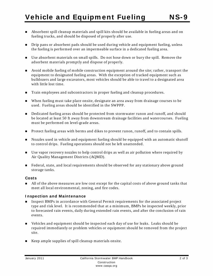
Vehicle and Equipment Fueling NS-9
January 2011 California Stormwater BMP Handbook 2 of 3 Construction www.casqa.org
Absorbent spill cleanup materials and spill kits should be available in fueling areas and on fueling trucks, and should be disposed of properly after use.
Drip pans or absorbent pads should be used during vehicle and equipment fueling, unless the fueling is performed over an impermeable surface in a dedicated fueling area.
Use absorbent materials on small spills. Do not hose down or bury the spill. Remove the adsorbent materials promptly and dispose of properly.
Avoid mobile fueling of mobile construction equipment around the site; rather, transport the equipment to designated fueling areas. With the exception of tracked equipment such as bulldozers and large excavators, most vehicles should be able to travel to a designated area with little lost time.
Train employees and subcontractors in proper fueling and cleanup procedures.
When fueling must take place onsite, designate an area away from drainage courses to be used. Fueling areas should be identified in the SWPPP.
Dedicated fueling areas should be protected from stormwater runon and runoff, and should be located at least 50 ft away from downstream drainage facilities and watercourses. Fueling must be performed on level-grade areas.
Protect fueling areas with berms and dikes to prevent runon, runoff, and to contain spills.
Nozzles used in vehicle and equipment fueling should be equipped with an automatic shutoff to control drips. Fueling operations should not be left unattended.
Use vapor recovery nozzles to help control drips as well as air pollution where required by Air Quality Management Districts (AQMD).
Federal, state, and local requirements should be observed for any stationary above ground storage tanks.
Costs All of the above measures are low cost except for the capital costs of above ground tanks that
meet all local environmental, zoning, and fire codes.
Inspection and Maintenance Inspect BMPs in accordance with General Permit requirements for the associated project
type and risk level. It is recommended that at a minimum, BMPs be inspected weekly, prior to forecasted rain events, daily during extended rain events, and after the conclusion of rain events.
Vehicles and equipment should be inspected each day of use for leaks. Leaks should be repaired immediately or problem vehicles or equipment should be removed from the project site.
Keep ample supplies of spill cleanup materials onsite.

Vehicle and Equipment Fueling NS-9
January 2011 California Stormwater BMP Handbook 3 of 3 Construction www.casqa.org
Immediately clean up spills and properly dispose of contaminated soil and cleanup materials.
References Blueprint for a Clean Bay: Best Management Practices to Prevent Stormwater Pollution from Construction Related Activities; Santa Clara Valley Nonpoint Source Pollution Control Program, 1995.
Coastal Nonpoint Pollution Control Program: Program Development and Approval Guidance, Working Group Working Paper; USEPA, April 1992.
Stormwater Quality Handbooks - Construction Site Best Management Practices (BMPs) Manual, State of California Department of Transportation (Caltrans), November 2000.
Stormwater Management for Construction Activities, Developing Pollution Prevention Plans and Best Management Practices, EPA 832-R-92005; USEPA, April 1992.

Vehicle & Equipment Maintenance NS-10
January 2011 California Stormwater BMP Handbook 1 of 4 Construction www.casqa.org
Description and Purpose Prevent or reduce the contamination of stormwater resulting from vehicle and equipment maintenance by running a “dry and clean site”. The best option would be to perform maintenance activities at an offsite facility. If this option is not available then work should be performed in designated areas only, while providing cover for materials stored outside, checking for leaks and spills, and containing and cleaning up spills immediately. Employees and subcontractors must be trained in proper procedures.
Suitable Applications These procedures are suitable on all construction projects where an onsite yard area is necessary for storage and maintenance of heavy equipment and vehicles.
Limitations Onsite vehicle and equipment maintenance should only be used where it is impractical to send vehicles and equipment offsite for maintenance and repair. Sending vehicles/equipment offsite should be done in conjunction with TC-1, Stabilized Construction Entrance/Exit.
Outdoor vehicle or equipment maintenance is a potentially significant source of stormwater pollution. Activities that can contaminate stormwater include engine repair and service, changing or replacement of fluids, and outdoor equipment storage and parking (engine fluid leaks). For further information on vehicle or equipment servicing, see NS-8,
Categories
EC Erosion Control
SE Sediment Control
TC Tracking Control
WE Wind Erosion Control
NS Non-Stormwater Management Control
WM Waste Management and Materials Pollution Control
Legend:
Primary Objective
Secondary Objective
Targeted Constituents
Sediment Nutrients Trash Metals Bacteria Oil and Grease Organics
Potential Alternatives
None
If User/Subscriber modifies this fact sheet in any way, the CASQA name/logo and footer below must be removed from each page and not appear on the modified version.
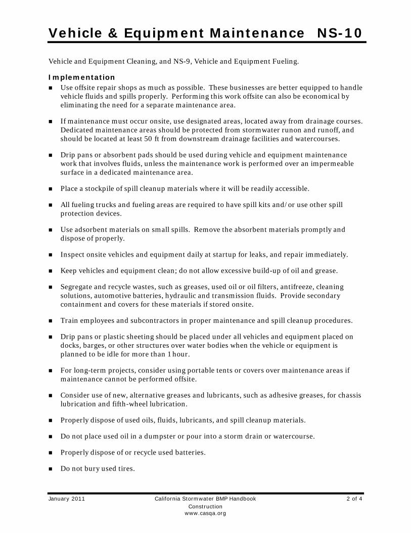
Vehicle & Equipment Maintenance NS-10
January 2011 California Stormwater BMP Handbook 2 of 4 Construction www.casqa.org
Vehicle and Equipment Cleaning, and NS-9, Vehicle and Equipment Fueling.
Implementation Use offsite repair shops as much as possible. These businesses are better equipped to handle
vehicle fluids and spills properly. Performing this work offsite can also be economical by eliminating the need for a separate maintenance area.
If maintenance must occur onsite, use designated areas, located away from drainage courses. Dedicated maintenance areas should be protected from stormwater runon and runoff, and should be located at least 50 ft from downstream drainage facilities and watercourses.
Drip pans or absorbent pads should be used during vehicle and equipment maintenance work that involves fluids, unless the maintenance work is performed over an impermeable surface in a dedicated maintenance area.
Place a stockpile of spill cleanup materials where it will be readily accessible.
All fueling trucks and fueling areas are required to have spill kits and/or use other spill protection devices.
Use adsorbent materials on small spills. Remove the absorbent materials promptly and dispose of properly.
Inspect onsite vehicles and equipment daily at startup for leaks, and repair immediately.
Keep vehicles and equipment clean; do not allow excessive build-up of oil and grease.
Segregate and recycle wastes, such as greases, used oil or oil filters, antifreeze, cleaning solutions, automotive batteries, hydraulic and transmission fluids. Provide secondary containment and covers for these materials if stored onsite.
Train employees and subcontractors in proper maintenance and spill cleanup procedures.
Drip pans or plastic sheeting should be placed under all vehicles and equipment placed on docks, barges, or other structures over water bodies when the vehicle or equipment is planned to be idle for more than 1 hour.
For long-term projects, consider using portable tents or covers over maintenance areas if maintenance cannot be performed offsite.
Consider use of new, alternative greases and lubricants, such as adhesive greases, for chassis lubrication and fifth-wheel lubrication.
Properly dispose of used oils, fluids, lubricants, and spill cleanup materials.
Do not place used oil in a dumpster or pour into a storm drain or watercourse.
Properly dispose of or recycle used batteries.
Do not bury used tires.

Vehicle & Equipment Maintenance NS-10
January 2011 California Stormwater BMP Handbook 3 of 4 Construction www.casqa.org
Repair leaks of fluids and oil immediately.
Listed below is further information if you must perform vehicle or equipment maintenance onsite.
Safer Alternative Products Consider products that are less toxic or hazardous than regular products. These products
are often sold under an “environmentally friendly” label.
Consider use of grease substitutes for lubrication of truck fifth-wheels. Follow manufacturers label for details on specific uses.
Consider use of plastic friction plates on truck fifth-wheels in lieu of grease. Follow manufacturers label for details on specific uses.
Waste Reduction Parts are often cleaned using solvents such as trichloroethylene, trichloroethane, or methylene chloride. Many of these cleaners are listed in California Toxic Rule as priority pollutants. These materials are harmful and must not contaminate stormwater. They must be disposed of as a hazardous waste. Reducing the number of solvents makes recycling easier and reduces hazardous waste management costs. Often, one solvent can perform a job as well as two different solvents. Also, if possible, eliminate or reduce the amount of hazardous materials and waste by substituting non-hazardous or less hazardous materials. For example, replace chlorinated organic solvents with non-chlorinated solvents. Non-chlorinated solvents like kerosene or mineral spirits are less toxic and less expensive to dispose of properly. Check the list of active ingredients to see whether it contains chlorinated solvents. The “chlor” term indicates that the solvent is chlorinated. Also, try substituting a wire brush for solvents to clean parts.
Recycling and Disposal Separating wastes allows for easier recycling and may reduce disposal costs. Keep hazardous wastes separate, do not mix used oil solvents, and keep chlorinated solvents (like,-trichloroethane) separate from non-chlorinated solvents (like kerosene and mineral spirits). Promptly transfer used fluids to the proper waste or recycling drums. Don’t leave full drip pans or other open containers lying around. Provide cover and secondary containment until these materials can be removed from the site.
Oil filters can be recycled. Ask your oil supplier or recycler about recycling oil filters.
Do not dispose of extra paints and coatings by dumping liquid onto the ground or throwing it into dumpsters. Allow coatings to dry or harden before disposal into covered dumpsters.
Store cracked batteries in a non-leaking secondary container. Do this with all cracked batteries, even if you think all the acid has drained out. If you drop a battery, treat it as if it is cracked. Put it into the containment area until you are sure it is not leaking.
Costs All of the above are low cost measures. Higher costs are incurred to setup and maintain onsite maintenance areas.

Vehicle & Equipment Maintenance NS-10
January 2011 California Stormwater BMP Handbook 4 of 4 Construction www.casqa.org
Inspection and Maintenance Inspect and verify that activity-based BMPs are in place prior to the commencement of
associated activities. While activities associated with the BMP are under way, inspect BMPs in accordance with General Permit requirements for the associated project type and risk level. It is recommended that at a minimum, BMPs be inspected weekly, prior to forecasted rain events, daily during extended rain events, and after the conclusion of rain events.
Inspect BMPs subject to non-stormwater discharges daily while non-stormwater discharges occur.
Keep ample supplies of spill cleanup materials onsite.
Maintain waste fluid containers in leak proof condition.
Vehicles and equipment should be inspected on each day of use. Leaks should be repaired immediately or the problem vehicle(s) or equipment should be removed from the project site.
Inspect equipment for damaged hoses and leaky gaskets routinely. Repair or replace as needed.
References Blueprint for a Clean Bay: Best Management Practices to Prevent Stormwater Pollution from Construction Related Activities; Santa Clara Valley Nonpoint Source Pollution Control Program, 1995.
Coastal Nonpoint Pollution Control Program; Program Development and Approval Guidance, Working Group, Working Paper; USEPA, April 1992.
Stormwater Quality Handbooks - Construction Site Best Management Practices (BMPs) Manual, State of California Department of Transportation (Caltrans), November 2000.

Material Over Water NS-14
January 2011 California Stormwater BMP Handbook 1 of 3 Construction www.casqa.org
Description and Purpose Procedures for the proper use, storage, and disposal of materials and equipment on barges, boats, temporary construction pads, or similar locations that minimize or eliminate the discharge of potential pollutants to a watercourse.
Suitable Applications Applies where materials and equipment are used on barges, boats, docks, and other platforms over or adjacent to a watercourse including waters of the United States. These procedures should be implemented for construction materials and wastes (solid and liquid), soil or dredging materials, or any other materials that may cause or contribute to exceedances of water quality standards.
Limitations Dredge and fill activities are regulated by the US Army Corps of Engineers and Regional Boards under Section 404/401 of the Clean Water Act.
Implementation Refer to WM-1, Material Delivery and Storage and WM-4,
Spill Prevention and Control.
Use drip pans and absorbent materials for equipment and vehicles and ensure that an adequate supply of spill clean up materials is available.
Drip pans should be placed under all vehicles and equipment placed on docks, barges, or other structures over
Categories
EC Erosion Control
SE Sediment Control
TC Tracking Control
WE Wind Erosion Control
NS Non-Stormwater Management Control
WM Waste Management and Materials Pollution Control
Legend:
Primary Objective
Secondary Objective
Targeted Constituents
Sediment
Nutrients
Trash
Metals
Bacteria
Oil and Grease
Organics
Potential Alternatives
None
If User/Subscriber modifies this fact sheet in any way, the CASQA name/logo and footer below must be removed from each page and not appear on the modified version.

Material Over Water NS-14
January 2011 California Stormwater BMP Handbook 2 of 3 Construction www.casqa.org
water bodies when the vehicle or equipment is expected to be idle for more than 1 hour.
Maintain equipment in accordance with NS-10, Vehicle and Equipment Maintenance. If a leaking line cannot be repaired, remove equipment from over the water.
Provide watertight curbs or toe boards to contain spills and prevent materials, tools, and debris from leaving the barge, platform, dock, etc.
Secure all materials to prevent discharges to receiving waters via wind.
Identify types of spill control measures to be employed, including the storage of such materials and equipment. Ensure that staff is trained regarding the use of the materials, deployment and access of control measures, and reporting measures.
In case of spills, contact the local Regional Board as soon as possible but within 48 hours.
Refer to WM-5, Solid Waste Management (non-hazardous) and WM-6, Hazardous Waste Management. Ensure the timely and proper removal of accumulated wastes
Comply with all necessary permits required for construction within or near the watercourse, such as Regional Water Quality Control Board, U.S. Army Corps of Engineers, Department of Fish and Game or and other local permitting.
Discharges to waterways should be reported to the Regional Water Quality Control Board immediately upon discovery. A written discharge notification must follow within 7 days. Follow the spill reporting procedures contained in SWPPP.
Costs These measures are generally of low to moderate cost. Exceptions are areas for temporary storage of materials, engine fluids, or wastewater pump out.
Inspection and Maintenance Inspect and verify that activity–based BMPs are in place prior to the commencement of
associated activities. While activities associated with the BMP are under way, inspect BMPs in accordance with General Permit requirements for the associated project type and risk level. It is recommended that at a minimum, BMPs be inspected weekly, prior to forecasted rain events, daily during extended rain events, and after the conclusion of rain events.
Inspect BMPs subject to non-stormwater discharge daily while non-stormwater discharges occur.
Ensure that employees and subcontractors implement the appropriate measures for storage and use of materials and equipment.
Inspect and maintain all associated BMPs and perimeter controls to ensure continuous protection of the water courses, including waters of the United States.
References Stormwater Quality Handbooks - Construction Site Best Management Practices (BMPs) Manual, State of California Department of Transportation (Caltrans), November 2000.

Material Over Water NS-14
January 2011 California Stormwater BMP Handbook 3 of 3 Construction www.casqa.org
Stormwater Management for Construction Activities, Developing Pollution Prevention Plans and Best Management Practices, EPA 832-R-92005; USEPA, April 1992.

Demolition Adjacent to Water NS-15
January 2011 California Stormwater BMP Handbook 1 of 2 Construction www.casqa.org
Description and Purpose Procedures to protect water bodies from debris and wastes associated with structure demolition or removal over or adjacent to watercourses.
Suitable Applications Full bridge demolition and removal, partial bridge removal (barrier rail, edge of deck) associated with bridge widening projects, concrete channel removal, or any other structure removal that could potentially affect water quality.
Limitations None identified.
Implementation Refer to NS-5, Clear Water Diversion, to direct water away
from work areas.
Use attachments on construction equipment such as backhoes to catch debris from small demolition operations.
Use covers or platforms to collect debris.
Platforms and covers are to be approved by the owner.
Stockpile accumulated debris and waste generated during demolition away from watercourses and in accordance with WM-3, Stockpile Management.
Ensure safe passage of wildlife, as necessary.
Categories
EC Erosion Control
SE Sediment Control
TC Tracking Control
WE Wind Erosion Control
NS Non-Stormwater Management Control
WM Waste Management and Materials Pollution Control
Legend:
Primary Objective
Secondary Objective
Targeted Constituents
Sediment
Nutrients
Trash
Metals
Bacteria
Oil and Grease
Organics
Potential Alternatives
None
If User/Subscriber modifies this fact sheet in any way, the CASQA name/logo and footer below must be removed from each page and not appear on the modified version.

Demolition Adjacent to Water NS-15
January 2011 California Stormwater BMP Handbook 2 of 2 Construction www.casqa.org
Discharges to waterways shall be reported to the Regional Water Quality Control Board immediately upon discovery. A written discharge notification must follow within 7 days. Follow the spill reporting procedures in the SWPPP.
For structures containing hazardous materials, i.e., lead paint or asbestos, refer to BMP WM-6, Hazardous Waste Management. For demolition work involving soil excavation around lead-painted structures, refer to WM-7, Contaminated Soil Management.
Costs Cost may vary according to the combination of practices implemented.
Inspection and Maintenance Inspect and verify that activity–based BMPs are in place prior to the commencement of
associated activities. While activities associated with the BMP are under way, inspect BMPs in accordance with General Permit requirements for the associated project type and risk level. It is recommended that at a minimum, BMPs be inspected weekly, prior to forecasted rain events, daily during extended rain events, and after the conclusion of rain events.
Inspect BMPs subject to non-stormwater discharge daily while non-stormwater discharges occur.
Any debris-catching devices shall be emptied regularly. Collected debris shall be removed and stored away from the watercourse and protected from runon and runoff.
References Stormwater Quality Handbooks - Construction Site Best Management Practices (BMPs) Manual, State of California Department of Transportation (Caltrans), November 2000.
Stormwater Management for Construction Activities, Developing Pollution Prevention Plans and Best Management Practices, EPA 832-R-92005; USEPA, April 1992.

Material Delivery and Storage WM-1
November 2009 California Stormwater BMP Handbook 1 of 5 Construction www.casqa.org
Description and Purpose Prevent, reduce, or eliminate the discharge of pollutants from material delivery and storage to the stormwater system or watercourses by minimizing the storage of hazardous materials onsite, storing materials in watertight containers and/or a completely enclosed designated area, installing secondary containment, conducting regular inspections, and training employees and subcontractors.
This best management practice covers only material delivery and storage. For other information on materials, see WM-2, Material Use, or WM-4, Spill Prevention and Control. For information on wastes, see the waste management BMPs in this section.
Suitable Applications These procedures are suitable for use at all construction sites with delivery and storage of the following materials:
Soil stabilizers and binders
Pesticides and herbicides
Fertilizers
Detergents
Plaster
Petroleum products such as fuel, oil, and grease
Categories
EC Erosion Control
SE Sediment Control
TC Tracking Control
WE Wind Erosion Control
NS Non-Stormwater Management Control
WM Waste Management and Materials Pollution Control
Legend:
Primary Category
Secondary Category
Targeted Constituents
Sediment Nutrients Trash Metals Bacteria Oil and Grease Organics
Potential Alternatives
None
If User/Subscriber modifies this fact sheet in any way, the CASQA name/logo and footer below must be removed from each page and not appear on the modified version.

Material Delivery and Storage WM-1
November 2009 California Stormwater BMP Handbook 2 of 5 Construction www.casqa.org
Asphalt and concrete components
Hazardous chemicals such as acids, lime, glues, adhesives, paints, solvents, and curing compounds
Concrete compounds
Other materials that may be detrimental if released to the environment
Limitations Space limitation may preclude indoor storage.
Storage sheds often must meet building and fire code requirements.
Implementation The following steps should be taken to minimize risk:
Chemicals must be stored in water tight containers with appropriate secondary containment or in a storage shed.
When a material storage area is located on bare soil, the area should be lined and bermed.
Use containment pallets or other practical and available solutions, such as storing materials within newly constructed buildings or garages, to meet material storage requirements.
Stack erodible landscape material on pallets and cover when not in use.
Contain all fertilizers and other landscape materials when not in use.
Temporary storage areas should be located away from vehicular traffic.
Material Safety Data Sheets (MSDS) should be available on-site for all materials stored that have the potential to effect water quality.
Construction site areas should be designated for material delivery and storage.
Material delivery and storage areas should be located away from waterways, if possible.
Avoid transport near drainage paths or waterways.
Surround with earth berms or other appropriate containment BMP. See EC-9, Earth Dikes and Drainage Swales.
Place in an area that will be paved.
Storage of reactive, ignitable, or flammable liquids must comply with the fire codes of your area. Contact the local Fire Marshal to review site materials, quantities, and proposed storage area to determine specific requirements. See the Flammable and Combustible Liquid Code, NFPA30.
An up to date inventory of materials delivered and stored onsite should be kept.

Material Delivery and Storage WM-1
November 2009 California Stormwater BMP Handbook 3 of 5 Construction www.casqa.org
Hazardous materials storage onsite should be minimized.
Hazardous materials should be handled as infrequently as possible.
Keep ample spill cleanup supplies appropriate for the materials being stored. Ensure that cleanup supplies are in a conspicuous, labeled area.
Employees and subcontractors should be trained on the proper material delivery and storage practices.
Employees trained in emergency spill cleanup procedures must be present when dangerous materials or liquid chemicals are unloaded.
If significant residual materials remain on the ground after construction is complete, properly remove and dispose of materials and any contaminated soil. See WM-7, Contaminated Soil Management. If the area is to be paved, pave as soon as materials are removed to stabilize the soil.
Material Storage Areas and Practices Liquids, petroleum products, and substances listed in 40 CFR Parts 110, 117, or 302 should
be stored in approved containers and drums and should not be overfilled. Containers and drums should be placed in temporary containment facilities for storage.
A temporary containment facility should provide for a spill containment volume able to contain precipitation from a 25 year storm event, plus the greater of 10% of the aggregate volume of all containers or 100% of the capacity of the largest container within its boundary, whichever is greater.
A temporary containment facility should be impervious to the materials stored therein for a minimum contact time of 72 hours.
A temporary containment facility should be maintained free of accumulated rainwater and spills. In the event of spills or leaks, accumulated rainwater and spills should be collected and placed into drums. These liquids should be handled as a hazardous waste unless testing determines them to be non-hazardous. All collected liquids or non-hazardous liquids should be sent to an approved disposal site.
Sufficient separation should be provided between stored containers to allow for spill cleanup and emergency response access.
Incompatible materials, such as chlorine and ammonia, should not be stored in the same temporary containment facility.
Materials should be covered prior to, and during rain events.
Materials should be stored in their original containers and the original product labels should be maintained in place in a legible condition. Damaged or otherwise illegible labels should be replaced immediately.

Material Delivery and Storage WM-1
November 2009 California Stormwater BMP Handbook 4 of 5 Construction www.casqa.org
Bagged and boxed materials should be stored on pallets and should not be allowed to accumulate on the ground. To provide protection from wind and rain throughout the rainy season, bagged and boxed materials should be covered during non-working days and prior to and during rain events.
Stockpiles should be protected in accordance with WM-3, Stockpile Management.
Materials should be stored indoors within existing structures or completely enclosed storage sheds when available.
Proper storage instructions should be posted at all times in an open and conspicuous location.
An ample supply of appropriate spill clean up material should be kept near storage areas.
Also see WM-6, Hazardous Waste Management, for storing of hazardous wastes.
Material Delivery Practices Keep an accurate, up-to-date inventory of material delivered and stored onsite.
Arrange for employees trained in emergency spill cleanup procedures to be present when dangerous materials or liquid chemicals are unloaded.
Spill Cleanup Contain and clean up any spill immediately.
Properly remove and dispose of any hazardous materials or contaminated soil if significant residual materials remain on the ground after construction is complete. See WM-7, Contaminated Soil Management.
See WM-4, Spill Prevention and Control, for spills of chemicals and/or hazardous materials.
If spills or leaks of materials occur that are not contained and could discharge to surface waters, non-visible sampling of site discharge may be required. Refer to the General Permit or to your project specific Construction Site Monitoring Plan to determine if and where sampling is required.
Cost The largest cost of implementation may be in the construction of a materials storage area
that is covered and provides secondary containment.
Inspection and Maintenance BMPs must be inspected in accordance with General Permit requirements for the associated
project type and risk level. It is recommended that at a minimum, BMPs be inspected weekly, prior to forecasted rain events, daily during extended rain events, and after the conclusion of rain events.
Keep storage areas clean and well organized, including a current list of all materials onsite.
Inspect labels on containers for legibility and accuracy.

Material Delivery and Storage WM-1
November 2009 California Stormwater BMP Handbook 5 of 5 Construction www.casqa.org
Repair or replace perimeter controls, containment structures, covers, and liners as needed to maintain proper function.
References Blueprint for a Clean Bay: Best Management Practices to Prevent Stormwater Pollution from Construction Related Activities; Santa Clara Valley Nonpoint Source Pollution Control Program, 1995.
Coastal Nonpoint Pollution Control Program: Program Development and Approval Guidance, Working Group Working Paper; USEPA, April 1992.
Stormwater Quality Handbooks - Construction Site Best Management Practices (BMPs) Manual, State of California Department of Transportation (Caltrans), March 2003.
Stormwater Management for Construction Activities; Developing Pollution Prevention Plans and Best Management Practice, EPA 832-R-92005; USEPA, April 1992.

Material Use WM-2
November 2009 California Stormwater BMP Handbook 1 of 4 Construction www.casqa.org
Description and Purpose Prevent or reduce the discharge of pollutants to the storm drain system or watercourses from material use by using alternative products, minimizing hazardous material use onsite, and training employees and subcontractors.
Suitable Applications This BMP is suitable for use at all construction projects. These procedures apply when the following materials are used or prepared onsite:
Pesticides and herbicides
Fertilizers
Detergents
Petroleum products such as fuel, oil, and grease
Asphalt and other concrete components
Other hazardous chemicals such as acids, lime, glues, adhesives, paints, solvents, and curing compounds
Other materials that may be detrimental if released to the environment
Categories
EC Erosion Control
SE Sediment Control
TC Tracking Control
WE Wind Erosion Control
NS Non-Stormwater Management Control
WM Waste Management and Materials Pollution Control
Legend:
Primary Category
Secondary Category
Targeted Constituents
Sediment Nutrients Trash Metals Bacteria Oil and Grease Organics
Potential Alternatives
None
If User/Subscriber modifies this fact sheet in any way, the CASQA name/logo and footer below must be removed from each page and not appear on the modified version.

Material Use WM-2
November 2009 California Stormwater BMP Handbook 2 of 4 Construction www.casqa.org
Limitations Safer alternative building and construction products may not be available or suitable in every instance.
Implementation The following steps should be taken to minimize risk:
Minimize use of hazardous materials onsite.
Follow manufacturer instructions regarding uses, protective equipment, ventilation, flammability, and mixing of chemicals.
Train personnel who use pesticides. The California Department of Pesticide Regulation and county agricultural commissioners license pesticide dealers, certify pesticide applicators, and conduct onsite inspections.
The preferred method of termiticide application is soil injection near the existing or proposed structure foundation/slab; however, if not feasible, soil drench application of termiticides should follow EPA label guidelines and the following recommendations (most of which are applicable to most pesticide applications):
Do not treat soil that is water-saturated or frozen.
Application shall not commence within 24-hours of a predicted precipitation event with a 40% or greater probability. Weather tracking must be performed on a daily basis prior to termiticide application and during the period of termiticide application.
Do not allow treatment chemicals to runoff from the target area. Apply proper quantity to prevent excess runoff. Provide containment for and divert stormwater from application areas using berms or diversion ditches during application.
Dry season: Do not apply within 10 feet of storm drains. Do not apply within 25 feet of aquatic habitats (such as, but not limited to, lakes; reservoirs; rivers; permanent streams; marshes or ponds; estuaries; and commercial fish farm ponds).
Wet season: Do not apply within 50 feet of storm drains or aquatic habitats (such as, but not limited to, lakes; reservoirs; rivers; permanent streams; marshes or ponds; estuaries; and commercial fish farm ponds) unless a vegetative buffer is present (if so, refer to dry season requirements).
Do not make on-grade applications when sustained wind speeds are above 10 mph (at application site) at nozzle end height.
Cover treatment site prior to a rain event in order to prevent run-off of the pesticide into non-target areas. The treated area should be limited to a size that can be backfilled and/or covered by the end of the work shift. Backfilling or covering of the treated area shall be done by the end of the same work shift in which the application is made.
The applicator must either cover the soil him/herself or provide written notification of the above requirement to the contractor on site and to the person commissioning the

Material Use WM-2
November 2009 California Stormwater BMP Handbook 3 of 4 Construction www.casqa.org
application (if different than the contractor). If notice is provided to the contractor or the person commissioning the application, then they are responsible under the Federal Insecticide Fungicide, and Rodenticide Act (FIFRA) to ensure that: 1) if the concrete slab cannot be poured over the treated soil within 24 hours of application, the treated soil is covered with a waterproof covering (such as polyethylene sheeting), and 2) the treated soil is covered if precipitation is predicted to occur before the concrete slab is scheduled to be poured.
Do not over-apply fertilizers, herbicides, and pesticides. Prepare only the amount needed. Follow the recommended usage instructions. Over-application is expensive and environmentally harmful. Unless on steep slopes, till fertilizers into the soil rather than hydraulic application. Apply surface dressings in several smaller applications, as opposed to one large application, to allow time for infiltration and to avoid excess material being carried offsite by runoff. Do not apply these chemicals before predicted rainfall.
Train employees and subcontractors in proper material use.
Supply Material Safety Data Sheets (MSDS) for all materials.
Dispose of latex paint and paint cans, used brushes, rags, absorbent materials, and drop cloths, when thoroughly dry and are no longer hazardous, with other construction debris.
Do not remove the original product label; it contains important safety and disposal information. Use the entire product before disposing of the container.
Mix paint indoors or in a containment area. Never clean paintbrushes or rinse paint containers into a street, gutter, storm drain, or watercourse. Dispose of any paint thinners, residue, and sludge(s) that cannot be recycled, as hazardous waste.
For water-based paint, clean brushes to the extent practicable, and rinse to a drain leading to a sanitary sewer where permitted, or contain for proper disposal off site. For oil-based paints, clean brushes to the extent practicable, and filter and reuse thinners and solvents.
Use recycled and less hazardous products when practical. Recycle residual paints, solvents, non-treated lumber, and other materials.
Use materials only where and when needed to complete the construction activity. Use safer alternative materials as much as possible. Reduce or eliminate use of hazardous materials onsite when practical.
Document the location, time, chemicals applied, and applicator’s name and qualifications.
Keep an ample supply of spill clean up material near use areas. Train employees in spill clean up procedures.
Avoid exposing applied materials to rainfall and runoff unless sufficient time has been allowed for them to dry.
Discontinue use of erodible landscape material within 2 days prior to a forecasted rain event and materials should be covered and/or bermed.

Material Use WM-2
November 2009 California Stormwater BMP Handbook 4 of 4 Construction www.casqa.org
Provide containment for material use areas such as masons’ areas or paint mixing/preparation areas to prevent materials/pollutants from entering stormwater.
Costs All of the above are low cost measures.
Inspection and Maintenance Inspect and verify that activity-based BMPs are in place prior to the commencement of
associated activities.
BMPs must be inspected in accordance with General Permit requirements for the associated project type and risk level. It is recommended that at a minimum, BMPs be inspected weekly, prior to forecasted rain events, daily during extended rain events, and after the conclusion of rain events.
Ensure employees and subcontractors throughout the job are using appropriate practices.
References Blueprint for a Clean Bay: Best Management Practices to Prevent Stormwater Pollution from Construction Related Activities; Santa Clara Valley Nonpoint Source Pollution Control Program, 1995.
Coastal Nonpoint Pollution Control Program: Program Development and Approval Guidance, Working Group Working Paper; USEPA, April 1992.
Comments on Risk Assessments Risk Reduction Options for Cypermethrin: Docket No. OPP–2005–0293; California Stormwater Quality Association (CASQA) letter to USEPA, 2006.Environmental Hazard and General Labeling for Pyrethroid Non-Agricultural Outdoor Products, EPA-HQ-OPP-2008-0331-0021; USEPA, 2008.
Stormwater Quality Handbooks - Construction Site Best Management Practices (BMPs) Manual, State of California Department of Transportation (Caltrans), March 2003.
Stormwater Management for Construction Activities; Developing Pollution Prevention Plans and Best Management Practice, EPA 832-R-92005; USEPA, April 1992.

Stockpile Management WM-3
July 2012 California Stormwater BMP Handbook 1 of 3 Construction www.casqa.org
Description and Purpose Stockpile management procedures and practices are designed to reduce or eliminate air and stormwater pollution from stockpiles of soil, soil amendments, sand, paving materials such as portland cement concrete (PCC) rubble, asphalt concrete (AC), asphalt concrete rubble, aggregate base, aggregate sub base or pre-mixed aggregate, asphalt minder (so called “cold mix” asphalt), and pressure treated wood.
Suitable Applications Implement in all projects that stockpile soil and other loose materials.
Limitations Plastic sheeting as a stockpile protection is temporary and
hard to manage in windy conditions. Where plastic is used, consider use of plastic tarps with nylon reinforcement which may be more durable than standard sheeting.
Plastic sheeting can increase runoff volume due to lack of infiltration and potentially cause perimeter control failure.
Plastic sheeting breaks down faster in sunlight.
The use of Plastic materials and photodegradable plastics should be avoided.
Implementation Protection of stockpiles is a year-round requirement. To properly manage stockpiles:
Categories
EC Erosion Control
SE Sediment Control
TC Tracking Control
WE Wind Erosion Control
NS Non-Stormwater Management Control
WM Waste Management and Materials Pollution Control
Legend:
Primary Category
Secondary Category
Targeted Constituents
Sediment Nutrients Trash Metals Bacteria Oil and Grease Organics
Potential Alternatives
None
If User/Subscriber modifies this fact sheet in any way, the CASQA name/logo and footer below must be removed from each page and not appear on the modified version.

Stockpile Management WM-3
July 2012 California Stormwater BMP Handbook 2 of 3 Construction www.casqa.org
On larger sites, a minimum of 50 ft separation from concentrated flows of stormwater, drainage courses, and inlets is recommended.
After 14 days of inactivity, a stockpile is non-active and requires further protection described below. All stockpiles are required to be protected as non-active stockpiles immediately if they are not scheduled to be used within 14 days.
Protect all stockpiles from stormwater runon using temporary perimeter sediment barriers such as compost berms (SE-13), temporary silt dikes (SE-12), fiber rolls (SE-5), silt fences (SE-1), sandbags (SE-8), gravel bags (SE-6), or biofilter bags (SE-14). Refer to the individual fact sheet for each of these controls for installation information.
Implement wind erosion control practices as appropriate on all stockpiled material. For specific information, see WE-1, Wind Erosion Control.
Manage stockpiles of contaminated soil in accordance with WM-7, Contaminated Soil Management.
Place bagged materials on pallets and under cover.
Ensure that stockpile coverings are installed securely to protect from wind and rain.
Some plastic covers withstand weather and sunlight better than others. Select cover materials or methods based on anticipated duration of use.
Protection of Non-Active Stockpiles A stockpile is considered non-active if it either is not used for 14 days or if it is scheduled not to be used for 14 days or more. Stockpiles need to be protected immediately if they are not scheduled to be used within 14 days. Non-active stockpiles of the identified materials should be protected as follows:
Soil stockpiles Soil stockpiles should be covered or protected with soil stabilization measures and a
temporary perimeter sediment barrier at all times.
Temporary vegetation should be considered for topsoil piles that will be stockpiled for extended periods.
Stockpiles of Portland cement concrete rubble, asphalt concrete, asphalt concrete rubble, aggregate base, or aggregate sub base Stockpiles should be covered and protected with a temporary perimeter sediment barrier at
all times.
Stockpiles of “cold mix” Cold mix stockpiles should be placed on and covered with plastic sheeting or comparable
material at all times and surrounded by a berm.
Stockpiles of fly ash, stucco, hydrated lime

Stockpile Management WM-3
July 2012 California Stormwater BMP Handbook 3 of 3 Construction www.casqa.org
Stockpiles of materials that may raise the pH of runoff (i.e., basic materials) should be covered with plastic and surrounded by a berm.
Stockpiles/Storage of wood (Pressure treated with chromated copper arsenate or ammoniacal copper zinc arsenate Treated wood should be covered with plastic sheeting or comparable material at all times
and surrounded by a berm.
Protection of Active Stockpiles A stockpile is active when it is being used or is scheduled to be used within 14 days of the previous use. Active stockpiles of the identified materials should be protected as follows:
All stockpiles should be covered and protected with a temporary linear sediment barrier prior to the onset of precipitation.
Stockpiles of “cold mix” and treated wood, and basic materials should be placed on and covered with plastic sheeting or comparable material and surrounded by a berm prior to the onset of precipitation.
The downstream perimeter of an active stockpile should be protected with a linear sediment barrier or berm and runoff should be diverted around or away from the stockpile on the upstream perimeter.
Costs For cost information associated with stockpile protection refer to the individual erosion or sediment control BMP fact sheet considered for implementation (For example, refer to SE-1 Silt Fence for installation of silt fence around the perimeter of a stockpile.)
Inspection and Maintenance Stockpiles must be inspected in accordance with General Permit requirements for the
associated project type and risk level. It is recommended that at a minimum, BMPs be inspected weekly, prior to forecasted rain events, daily during extended rain events, and after the conclusion of rain events.
It may be necessary to inspect stockpiles covered with plastic sheeting more frequently during certain conditions (for example, high winds or extreme heat).
Repair and/or replace perimeter controls and covers as needed to keep them functioning properly.
Sediment shall be removed when it reaches one-third of the barrier height.
References Stormwater Quality Handbooks - Construction Site Best Management Practices (BMPs) Manual, State of California Department of Transportation (Caltrans), March 2003.

Spill Prevention and Control WM-4
January 2011 California Stormwater BMP Handbook 1 of 6 Construction www.casqa.org
Description and Purpose Prevent or reduce the discharge of pollutants to drainage systems or watercourses from leaks and spills by reducing the chance for spills, stopping the source of spills, containing and cleaning up spills, properly disposing of spill materials, and training employees.
This best management practice covers only spill prevention and control. However, WM-1, Materials Delivery and Storage, and WM-2, Material Use, also contain useful information, particularly on spill prevention. For information on wastes, see the waste management BMPs in this section.
Suitable Applications This BMP is suitable for all construction projects. Spill control procedures are implemented anytime chemicals or hazardous substances are stored on the construction site, including the following materials:
Soil stabilizers/binders
Dust palliatives
Herbicides
Growth inhibitors
Fertilizers
Deicing/anti-icing chemicals
Categories
EC Erosion Control
SE Sediment Control
TC Tracking Control
WE Wind Erosion Control
NS Non-Stormwater Management Control
WM Waste Management and Materials Pollution Control
Legend:
Primary Objective
Secondary Objective
Targeted Constituents
Sediment
Nutrients
Trash
Metals
Bacteria Oil and Grease
Organics
Potential Alternatives
None
If User/Subscriber modifies this fact sheet in any way, the CASQA name/logo and footer below must be removed from each page and not appear on the modified version.

Spill Prevention and Control WM-4
January 2011 California Stormwater BMP Handbook 2 of 6 Construction www.casqa.org
Fuels
Lubricants
Other petroleum distillates
Limitations In some cases it may be necessary to use a private spill cleanup company.
This BMP applies to spills caused by the contractor and subcontractors.
Procedures and practices presented in this BMP are general. Contractor should identify appropriate practices for the specific materials used or stored onsite
Implementation The following steps will help reduce the stormwater impacts of leaks and spills:
Education Be aware that different materials pollute in different amounts. Make sure that each
employee knows what a “significant spill” is for each material they use, and what is the appropriate response for “significant” and “insignificant” spills.
Educate employees and subcontractors on potential dangers to humans and the environment from spills and leaks.
Hold regular meetings to discuss and reinforce appropriate disposal procedures (incorporate into regular safety meetings).
Establish a continuing education program to indoctrinate new employees.
Have contractor’s superintendent or representative oversee and enforce proper spill prevention and control measures.
General Measures To the extent that the work can be accomplished safely, spills of oil, petroleum products,
substances listed under 40 CFR parts 110,117, and 302, and sanitary and septic wastes should be contained and cleaned up immediately.
Store hazardous materials and wastes in covered containers and protect from vandalism.
Place a stockpile of spill cleanup materials where it will be readily accessible.
Train employees in spill prevention and cleanup.
Designate responsible individuals to oversee and enforce control measures.
Spills should be covered and protected from stormwater runon during rainfall to the extent that it doesn’t compromise clean up activities.
Do not bury or wash spills with water.

Spill Prevention and Control WM-4
January 2011 California Stormwater BMP Handbook 3 of 6 Construction www.casqa.org
Store and dispose of used clean up materials, contaminated materials, and recovered spill material that is no longer suitable for the intended purpose in conformance with the provisions in applicable BMPs.
Do not allow water used for cleaning and decontamination to enter storm drains or watercourses. Collect and dispose of contaminated water in accordance with WM-10, Liquid Waste Management.
Contain water overflow or minor water spillage and do not allow it to discharge into drainage facilities or watercourses.
Place proper storage, cleanup, and spill reporting instructions for hazardous materials stored or used on the project site in an open, conspicuous, and accessible location.
Keep waste storage areas clean, well organized, and equipped with ample cleanup supplies as appropriate for the materials being stored. Perimeter controls, containment structures, covers, and liners should be repaired or replaced as needed to maintain proper function.
Cleanup Clean up leaks and spills immediately.
Use a rag for small spills on paved surfaces, a damp mop for general cleanup, and absorbent material for larger spills. If the spilled material is hazardous, then the used cleanup materials are also hazardous and must be sent to either a certified laundry (rags) or disposed of as hazardous waste.
Never hose down or bury dry material spills. Clean up as much of the material as possible and dispose of properly. See the waste management BMPs in this section for specific information.
Minor Spills Minor spills typically involve small quantities of oil, gasoline, paint, etc. which can be
controlled by the first responder at the discovery of the spill.
Use absorbent materials on small spills rather than hosing down or burying the spill.
Absorbent materials should be promptly removed and disposed of properly.
Follow the practice below for a minor spill:
Contain the spread of the spill.
Recover spilled materials.
Clean the contaminated area and properly dispose of contaminated materials.
Semi-Significant Spills Semi-significant spills still can be controlled by the first responder along with the aid of
other personnel such as laborers and the foreman, etc. This response may require the cessation of all other activities.

Spill Prevention and Control WM-4
January 2011 California Stormwater BMP Handbook 4 of 6 Construction www.casqa.org
Spills should be cleaned up immediately:
Contain spread of the spill.
Notify the project foreman immediately.
If the spill occurs on paved or impermeable surfaces, clean up using "dry" methods (absorbent materials, cat litter and/or rags). Contain the spill by encircling with absorbent materials and do not let the spill spread widely.
If the spill occurs in dirt areas, immediately contain the spill by constructing an earthen dike. Dig up and properly dispose of contaminated soil.
If the spill occurs during rain, cover spill with tarps or other material to prevent contaminating runoff.
Significant/Hazardous Spills For significant or hazardous spills that cannot be controlled by personnel in the immediate
vicinity, the following steps should be taken:
Notify the local emergency response by dialing 911. In addition to 911, the contractor will notify the proper county officials. It is the contractor's responsibility to have all emergency phone numbers at the construction site.
Notify the Governor's Office of Emergency Services Warning Center, (916) 845-8911.
For spills of federal reportable quantities, in conformance with the requirements in 40 CFR parts 110,119, and 302, the contractor should notify the National Response Center at (800) 424-8802.
Notification should first be made by telephone and followed up with a written report.
The services of a spills contractor or a Haz-Mat team should be obtained immediately. Construction personnel should not attempt to clean up until the appropriate and qualified staffs have arrived at the job site.
Other agencies which may need to be consulted include, but are not limited to, the Fire Department, the Public Works Department, the Coast Guard, the Highway Patrol, the City/County Police Department, Department of Toxic Substances, California Division of Oil and Gas, Cal/OSHA, etc.
Reporting Report significant spills to local agencies, such as the Fire Department; they can assist in
cleanup.
Federal regulations require that any significant oil spill into a water body or onto an adjoining shoreline be reported to the National Response Center (NRC) at 800-424-8802 (24 hours).
Use the following measures related to specific activities:

Spill Prevention and Control WM-4
January 2011 California Stormwater BMP Handbook 5 of 6 Construction www.casqa.org
Vehicle and Equipment Maintenance If maintenance must occur onsite, use a designated area and a secondary containment,
located away from drainage courses, to prevent the runon of stormwater and the runoff of spills.
Regularly inspect onsite vehicles and equipment for leaks and repair immediately
Check incoming vehicles and equipment (including delivery trucks, and employee and subcontractor vehicles) for leaking oil and fluids. Do not allow leaking vehicles or equipment onsite.
Always use secondary containment, such as a drain pan or drop cloth, to catch spills or leaks when removing or changing fluids.
Place drip pans or absorbent materials under paving equipment when not in use.
Use absorbent materials on small spills rather than hosing down or burying the spill. Remove the absorbent materials promptly and dispose of properly.
Promptly transfer used fluids to the proper waste or recycling drums. Don’t leave full drip pans or other open containers lying around
Oil filters disposed of in trashcans or dumpsters can leak oil and pollute stormwater. Place the oil filter in a funnel over a waste oil-recycling drum to drain excess oil before disposal. Oil filters can also be recycled. Ask the oil supplier or recycler about recycling oil filters.
Store cracked batteries in a non-leaking secondary container. Do this with all cracked batteries even if you think all the acid has drained out. If you drop a battery, treat it as if it is cracked. Put it into the containment area until you are sure it is not leaking.
Vehicle and Equipment Fueling If fueling must occur onsite, use designate areas, located away from drainage courses, to
prevent the runon of stormwater and the runoff of spills.
Discourage “topping off” of fuel tanks.
Always use secondary containment, such as a drain pan, when fueling to catch spills/ leaks.
Costs Prevention of leaks and spills is inexpensive. Treatment and/ or disposal of contaminated soil or water can be quite expensive.
Inspection and Maintenance Inspect and verify that activity–based BMPs are in place prior to the commencement of
associated activities. While activities associated with the BMP are under way, inspect BMPs in accordance with General Permit requirements for the associated project type and risk level. It is recommended that at a minimum, BMPs be inspected weekly, prior to forecasted rain events, daily during extended rain events, and after the conclusion of rain events.

Spill Prevention and Control WM-4
January 2011 California Stormwater BMP Handbook 6 of 6 Construction www.casqa.org
Inspect BMPs subject to non-stormwater discharge daily while non-stormwater discharges occur.
Keep ample supplies of spill control and cleanup materials onsite, near storage, unloading, and maintenance areas.
Update your spill prevention and control plan and stock cleanup materials as changes occur in the types of chemicals onsite.
References Blueprint for a Clean Bay: Best Management Practices to Prevent Stormwater Pollution from Construction Related Activities; Santa Clara Valley Nonpoint Source Pollution Control Program, 1995.
Stormwater Quality Handbooks - Construction Site Best Management Practices (BMPs) Manual, State of California Department of Transportation (Caltrans), November 2000.
Stormwater Management for Construction Activities; Developing Pollution Prevention Plans and Best Management Practice, EPA 832-R-92005; USEPA, April 1992.

Solid Waste Management WM-5
January 2011 California Stormwater BMP Handbook 1 of 4 Construction www.casqa.org
Description and Purpose Solid waste management procedures and practices are designed to prevent or reduce the discharge of pollutants to stormwater from solid or construction waste by providing designated waste collection areas and containers, arranging for regular disposal, and training employees and subcontractors.
Suitable Applications This BMP is suitable for construction sites where the following wastes are generated or stored:
Solid waste generated from trees and shrubs removed during land clearing, demolition of existing structures (rubble), and building construction
Packaging materials including wood, paper, and plastic
Scrap or surplus building materials including scrap metals, rubber, plastic, glass pieces, and masonry products
Domestic wastes including food containers such as beverage cans, coffee cups, paper bags, plastic wrappers, and cigarettes
Construction wastes including brick, mortar, timber, steel and metal scraps, pipe and electrical cuttings, non-hazardous equipment parts, styrofoam and other materials used to transport and package construction materials
Categories
EC Erosion Control
SE Sediment Control
TC Tracking Control
WE Wind Erosion Control
NS Non-Stormwater Management Control
WM Waste Management and Materials Pollution Control
Legend:
Primary Objective
Secondary Objective
Targeted Constituents
Sediment
Nutrients
Trash
Metals
Bacteria Oil and Grease
Organics
Potential Alternatives
None
If User/Subscriber modifies this fact sheet in any way, the CASQA name/logo and footer below must be removed from each page and not appear on the modified version.
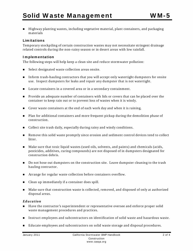
Solid Waste Management WM-5
January 2011 California Stormwater BMP Handbook 2 of 4 Construction www.casqa.org
Highway planting wastes, including vegetative material, plant containers, and packaging materials
Limitations Temporary stockpiling of certain construction wastes may not necessitate stringent drainage related controls during the non-rainy season or in desert areas with low rainfall.
Implementation The following steps will help keep a clean site and reduce stormwater pollution:
Select designated waste collection areas onsite.
Inform trash-hauling contractors that you will accept only watertight dumpsters for onsite use. Inspect dumpsters for leaks and repair any dumpster that is not watertight.
Locate containers in a covered area or in a secondary containment.
Provide an adequate number of containers with lids or covers that can be placed over the container to keep rain out or to prevent loss of wastes when it is windy.
Cover waste containers at the end of each work day and when it is raining.
Plan for additional containers and more frequent pickup during the demolition phase of construction.
Collect site trash daily, especially during rainy and windy conditions.
Remove this solid waste promptly since erosion and sediment control devices tend to collect litter.
Make sure that toxic liquid wastes (used oils, solvents, and paints) and chemicals (acids, pesticides, additives, curing compounds) are not disposed of in dumpsters designated for construction debris.
Do not hose out dumpsters on the construction site. Leave dumpster cleaning to the trash hauling contractor.
Arrange for regular waste collection before containers overflow.
Clean up immediately if a container does spill.
Make sure that construction waste is collected, removed, and disposed of only at authorized disposal areas.
Education Have the contractor’s superintendent or representative oversee and enforce proper solid
waste management procedures and practices.
Instruct employees and subcontractors on identification of solid waste and hazardous waste.
Educate employees and subcontractors on solid waste storage and disposal procedures.

Solid Waste Management WM-5
January 2011 California Stormwater BMP Handbook 3 of 4 Construction www.casqa.org
Hold regular meetings to discuss and reinforce disposal procedures (incorporate into regular safety meetings).
Require that employees and subcontractors follow solid waste handling and storage procedures.
Prohibit littering by employees, subcontractors, and visitors.
Minimize production of solid waste materials wherever possible.
Collection, Storage, and Disposal Littering on the project site should be prohibited.
To prevent clogging of the storm drainage system, litter and debris removal from drainage grates, trash racks, and ditch lines should be a priority.
Trash receptacles should be provided in the contractor’s yard, field trailer areas, and at locations where workers congregate for lunch and break periods.
Litter from work areas within the construction limits of the project site should be collected and placed in watertight dumpsters at least weekly, regardless of whether the litter was generated by the contractor, the public, or others. Collected litter and debris should not be placed in or next to drain inlets, stormwater drainage systems, or watercourses.
Dumpsters of sufficient size and number should be provided to contain the solid waste generated by the project.
Full dumpsters should be removed from the project site and the contents should be disposed of by the trash hauling contractor.
Construction debris and waste should be removed from the site biweekly or more frequently as needed.
Construction material visible to the public should be stored or stacked in an orderly manner.
Stormwater runon should be prevented from contacting stored solid waste through the use of berms, dikes, or other temporary diversion structures or through the use of measures to elevate waste from site surfaces.
Solid waste storage areas should be located at least 50 ft from drainage facilities and watercourses and should not be located in areas prone to flooding or ponding.
Except during fair weather, construction and highway planting waste not stored in watertight dumpsters should be securely covered from wind and rain by covering the waste with tarps or plastic.
Segregate potentially hazardous waste from non-hazardous construction site waste.
Make sure that toxic liquid wastes (used oils, solvents, and paints) and chemicals (acids, pesticides, additives, curing compounds) are not disposed of in dumpsters designated for construction debris.

Solid Waste Management WM-5
January 2011 California Stormwater BMP Handbook 4 of 4 Construction www.casqa.org
For disposal of hazardous waste, see WM-6, Hazardous Waste Management. Have hazardous waste hauled to an appropriate disposal and/or recycling facility.
Salvage or recycle useful vegetation debris, packaging and surplus building materials when practical. For example, trees and shrubs from land clearing can be used as a brush barrier, or converted into wood chips, then used as mulch on graded areas. Wood pallets, cardboard boxes, and construction scraps can also be recycled.
Costs All of the above are low cost measures.
Inspection and Maintenance Inspect and verify that activity–based BMPs are in place prior to the commencement of
associated activities. While activities associated with the BMP are under way, inspect BMPs in accordance with General Permit requirements for the associated project type and risk level. It is recommended that at a minimum, BMPs be inspected weekly, prior to forecasted rain events, daily during extended rain events, and after the conclusion of rain events.
Inspect BMPs subject to non-stormwater discharge daily while non-stormwater discharges occur
Inspect construction waste area regularly.
Arrange for regular waste collection.
References Processes, Procedures and Methods to Control Pollution Resulting from All Construction Activity, 430/9-73-007, USEPA, 1973.
Stormwater Quality Handbooks - Construction Site Best Management Practices (BMPs) Manual, State of California Department of Transportation (Caltrans), November 2000.
Stormwater Management for Construction Activities; Developing Pollution Prevention Plans and Best Management Practice, EPA 832-R-92005; USEPA, April 1992.

Contaminated Soil Management WM-7
January 2011 California Stormwater BMP Handbook 1 of 5 Construction www.casqa.org
Description and Purpose Prevent or reduce the discharge of pollutants to stormwater from contaminated soil and highly acidic or alkaline soils by conducting pre-construction surveys, inspecting excavations regularly, and remediating contaminated soil promptly.
Suitable Applications Contaminated soil management is implemented on construction projects in highly urbanized or industrial areas where soil contamination may have occurred due to spills, illicit discharges, aerial deposition, past use and leaks from underground storage tanks.
Limitations Contaminated soils that cannot be treated onsite must be disposed of offsite by a licensed hazardous waste hauler. The presence of contaminated soil may indicate contaminated water as well. See NS-2, Dewatering Operations, for more information.
The procedures and practices presented in this BMP are general. The contractor should identify appropriate practices and procedures for the specific contaminants known to exist or discovered onsite.
Implementation Most owners and developers conduct pre-construction environmental assessments as a matter of routine. Contaminated soils are often identified during project planning and development with known locations identified in the plans, specifications and in the SWPPP. The contractor should review applicable reports and investigate appropriate call-outs in the
Categories
EC Erosion Control
SE Sediment Control
TC Tracking Control
WE Wind Erosion Control
NS Non-Stormwater Management Control
WM Waste Management and Materials Pollution Control
Legend:
Primary Objective
Secondary Objective
Targeted Constituents
Sediment Nutrients
Trash
Metals
Bacteria
Oil and Grease
Organics
Potential Alternatives
None
If User/Subscriber modifies this fact sheet in any way, the CASQA name/logo and footer below must be removed from each page and not appear on the modified version.

Contaminated Soil Management WM-7
January 2011 California Stormwater BMP Handbook 2 of 5 Construction www.casqa.org
plans, specifications, and SWPPP. Recent court rulings holding contractors liable for cleanup costs when they unknowingly move contaminated soil highlight the need for contractors to confirm a site assessment is completed before earth moving begins.
The following steps will help reduce stormwater pollution from contaminated soil:
Conduct thorough, pre-construction inspections of the site and review documents related to the site. If inspection or reviews indicated presence of contaminated soils, develop a plan before starting work.
Look for contaminated soil as evidenced by discoloration, odors, differences in soil properties, abandoned underground tanks or pipes, or buried debris.
Prevent leaks and spills. Contaminated soil can be expensive to treat and dispose of properly. However, addressing the problem before construction is much less expensive than after the structures are in place.
The contractor may further identify contaminated soils by investigating:
Past site uses and activities
Detected or undetected spills and leaks
Acid or alkaline solutions from exposed soil or rock formations high in acid or alkaline forming elements
Contaminated soil as evidenced by discoloration, odors, differences in soil properties, abandoned underground tanks or pipes, or buried debris.
Suspected soils should be tested at a certified laboratory.
Education Have employees and subcontractors complete a safety training program which meets 29
CFR 1910.120 and 8 CCR 5192 covering the potential hazards as identified, prior to performing any excavation work at the locations containing material classified as hazardous.
Educate employees and subcontractors in identification of contaminated soil and on contaminated soil handling and disposal procedures.
Hold regular meetings to discuss and reinforce disposal procedures (incorporate into regular safety meetings).
Handling Procedures for Material with Aerially Deposited Lead (ADL) Materials from areas designated as containing (ADL) may, if allowed by the contract special
provisions, be excavated, transported, and used in the construction of embankments and/or backfill.
Excavation, transportation, and placement operations should result in no visible dust.
Caution should be exercised to prevent spillage of lead containing material during transport.

Contaminated Soil Management WM-7
January 2011 California Stormwater BMP Handbook 3 of 5 Construction www.casqa.org
Quality should be monitored during excavation of soils contaminated with lead.
Handling Procedures for Contaminated Soils Minimize onsite storage. Contaminated soil should be disposed of properly in accordance
with all applicable regulations. All hazardous waste storage will comply with the requirements in Title 22, CCR, Sections 66265.250 to 66265.260.
Test suspected soils at an approved certified laboratory.
Work with the local regulatory agencies to develop options for treatment or disposal if the soil is contaminated.
Avoid temporary stockpiling of contaminated soils or hazardous material.
Take the following precautions if temporary stockpiling is necessary:
Cover the stockpile with plastic sheeting or tarps.
Install a berm around the stockpile to prevent runoff from leaving the area.
Do not stockpile in or near storm drains or watercourses.
Remove contaminated material and hazardous material on exteriors of transport vehicles and place either into the current transport vehicle or into the excavation prior to the vehicle leaving the exclusion zone.
Monitor the air quality continuously during excavation operations at all locations containing hazardous material.
Procure all permits and licenses, pay all charges and fees, and give all notices necessary and incident to the due and lawful prosecution of the work, including registration for transporting vehicles carrying the contaminated material and the hazardous material.
Collect water from decontamination procedures and treat or dispose of it at an appropriate disposal site.
Collect non-reusable protective equipment, once used by any personnel, and dispose of at an appropriate disposal site.
Install temporary security fence to surround and secure the exclusion zone. Remove fencing when no longer needed.
Excavate, transport, and dispose of contaminated material and hazardous material in accordance with the rules and regulations of the following agencies (the specifications of these agencies supersede the procedures outlined in this BMP):
United States Department of Transportation (USDOT)
United States Environmental Protection Agency (USEPA)
California Environmental Protection Agency (CAL-EPA)

Contaminated Soil Management WM-7
January 2011 California Stormwater BMP Handbook 4 of 5 Construction www.casqa.org
California Division of Occupation Safety and Health Administration (CAL-OSHA)
Local regulatory agencies
Procedures for Underground Storage Tank Removals Prior to commencing tank removal operations, obtain the required underground storage
tank removal permits and approval from the federal, state, and local agencies that have jurisdiction over such work.
To determine if it contains hazardous substances, arrange to have tested, any liquid or sludge found in the underground tank prior to its removal.
Following the tank removal, take soil samples beneath the excavated tank and perform analysis as required by the local agency representative(s).
The underground storage tank, any liquid or sludge found within the tank, and all contaminated substances and hazardous substances removed during the tank removal and transported to disposal facilities permitted to accept such waste.
Water Control All necessary precautions and preventive measures should be taken to prevent the flow of
water, including ground water, from mixing with hazardous substances or underground storage tank excavations. Such preventative measures may consist of, but are not limited to, berms, cofferdams, grout curtains, freeze walls, and seal course concrete or any combination thereof.
If water does enter an excavation and becomes contaminated, such water, when necessary to proceed with the work, should be discharged to clean, closed top, watertight transportable holding tanks, treated, and disposed of in accordance with federal, state, and local laws.
Costs Prevention of leaks and spills is inexpensive. Treatment or disposal of contaminated soil can be quite expensive.
Inspection and Maintenance Inspect and verify that activity–based BMPs are in place prior to the commencement of
associated activities. While activities associated with the BMP are under way, inspect BMPs in accordance with General Permit requirements for the associated project type and risk level. It is recommended that at a minimum, BMPs be inspected weekly, prior to forecasted rain events, daily during extended rain events, and after the conclusion of rain events.
Arrange for contractor’s Water Pollution Control Manager, foreman, and/or construction supervisor to monitor onsite contaminated soil storage and disposal procedures.
Monitor air quality continuously during excavation operations at all locations containing hazardous material.
Coordinate contaminated soils and hazardous substances/waste management with the appropriate federal, state, and local agencies.

Contaminated Soil Management WM-7
January 2011 California Stormwater BMP Handbook 5 of 5 Construction www.casqa.org
Implement WM-4, Spill Prevention and Control, to prevent leaks and spills as much as possible.
References Blueprint for a Clean Bay: Best Management Practices to Prevent Stormwater Pollution from Construction Related Activities; Santa Clara Valley Nonpoint Source Pollution Control Program, 1995.
Processes, Procedures and Methods to Control Pollution Resulting from All Construction Activity, 430/9-73-007, USEPA, 1973.
Stormwater Quality Handbooks - Construction Site Best Management Practices (BMPs) Manual, State of California Department of Transportation (Caltrans), November 2000.
Stormwater Management for Construction Activities; Developing Pollution Prevention Plans and Best Management Practice, EPA 832-R-92005; USEPA, April 1992.


Concrete Waste Management WM-8
July 2012 California Stormwater BMP Handbook 1 of 7 Construction www.casqa.org
Description and Purpose Prevent the discharge of pollutants to stormwater from concrete waste by conducting washout onsite or offsite in a designated area, and by employee and subcontractor training.
The General Permit incorporates Numeric Action Levels (NAL) for pH (see Section 2 of this handbook to determine your project’s risk level and if you are subject to these requirements).
Many types of construction materials, including mortar, concrete, stucco, cement and block and their associated wastes have basic chemical properties that can raise pH levels outside of the permitted range. Additional care should be taken when managing these materials to prevent them from coming into contact with stormwater flows and raising pH to levels outside the accepted range.
Suitable Applications Concrete waste management procedures and practices are implemented on construction projects where:
Concrete is used as a construction material or where concrete dust and debris result from demolition activities.
Slurries containing portland cement concrete (PCC) are generated, such as from saw cutting, coring, grinding, grooving, and hydro-concrete demolition.
Concrete trucks and other concrete-coated equipment are washed onsite.
Categories
EC Erosion Control
SE Sediment Control
TC Tracking Control
WE Wind Erosion Control
NS Non-Stormwater Management Control
WM Waste Management and Materials Pollution Control
Legend:
Primary Category
Secondary Category
Targeted Constituents
Sediment Nutrients Trash Metals Bacteria Oil and Grease Organics
Potential Alternatives
None
If User/Subscriber modifies this fact sheet in any way, the CASQA name/logo and footer below must be removed from each page and not appear on the modified version.
Concrete Waste Management WM-8
July 2012 California Stormwater BMP Handbook 2 of 7 Construction www.casqa.org
Mortar-mixing stations exist.
Stucco mixing and spraying.
See also NS-8, Vehicle and Equipment Cleaning.
Limitations Offsite washout of concrete wastes may not always be possible.
Multiple washouts may be needed to assure adequate capacity and to allow for evaporation.
Implementation The following steps will help reduce stormwater pollution from concrete wastes:
Incorporate requirements for concrete waste management into material supplier and subcontractor agreements.
Store dry and wet materials under cover, away from drainage areas. Refer to WM-1, Material Delivery and Storage for more information.
Avoid mixing excess amounts of concrete.
Perform washout of concrete trucks in designated areas only, where washout will not reach stormwater.
Do not wash out concrete trucks into storm drains, open ditches, streets, streams or onto the ground. Trucks should always be washed out into designated facilities.
Do not allow excess concrete to be dumped onsite, except in designated areas.
For onsite washout:
On larger sites, it is recommended to locate washout areas at least 50 feet from storm drains, open ditches, or water bodies. Do not allow runoff from this area by constructing a temporary pit or bermed area large enough for liquid and solid waste.
Washout wastes into the temporary washout where the concrete can set, be broken up, and then disposed properly.
Washouts shall be implemented in a manner that prevents leaching to underlying soils. Washout containers must be water tight and washouts on or in the ground must be lined with a suitable impervious liner, typically a plastic type material.
Do not wash sweepings from exposed aggregate concrete into the street or storm drain. Collect and return sweepings to aggregate base stockpile or dispose in the trash.
See typical concrete washout installation details at the end of this fact sheet.
Education Educate employees, subcontractors, and suppliers on the concrete waste management
techniques described herein.

Concrete Waste Management WM-8
July 2012 California Stormwater BMP Handbook 3 of 7 Construction www.casqa.org
Arrange for contractor’s superintendent or representative to oversee and enforce concrete waste management procedures.
Discuss the concrete management techniques described in this BMP (such as handling of concrete waste and washout) with the ready-mix concrete supplier before any deliveries are made.
Concrete Demolition Wastes Stockpile concrete demolition waste in accordance with BMP WM-3, Stockpile Management.
Dispose of or recycle hardened concrete waste in accordance with applicable federal, state or local regulations.
Concrete Slurry Wastes PCC and AC waste should not be allowed to enter storm drains or watercourses.
PCC and AC waste should be collected and disposed of or placed in a temporary concrete washout facility (as described in Onsite Temporary Concrete Washout Facility, Concrete Transit Truck Washout Procedures, below).
A foreman or construction supervisor should monitor onsite concrete working tasks, such as saw cutting, coring, grinding and grooving to ensure proper methods are implemented.
Saw-cut concrete slurry should not be allowed to enter storm drains or watercourses. Residue from grinding operations should be picked up by means of a vacuum attachment to the grinding machine or by sweeping. Saw cutting residue should not be allowed to flow across the pavement and should not be left on the surface of the pavement. See also NS-3, Paving and Grinding Operations; and WM-10, Liquid Waste Management.
Concrete slurry residue should be disposed in a temporary washout facility (as described in Onsite Temporary Concrete Washout Facility, Concrete Transit Truck Washout Procedures, below) and allowed to dry. Dispose of dry slurry residue in accordance with WM-5, Solid Waste Management.
Onsite Temporary Concrete Washout Facility, Transit Truck Washout Procedures Temporary concrete washout facilities should be located a minimum of 50 ft from storm
drain inlets, open drainage facilities, and watercourses. Each facility should be located away from construction traffic or access areas to prevent disturbance or tracking.
A sign should be installed adjacent to each washout facility to inform concrete equipment operators to utilize the proper facilities.
Temporary concrete washout facilities should be constructed above grade or below grade at the option of the contractor. Temporary concrete washout facilities should be constructed and maintained in sufficient quantity and size to contain all liquid and concrete waste generated by washout operations.

Concrete Waste Management WM-8
July 2012 California Stormwater BMP Handbook 4 of 7 Construction www.casqa.org
Temporary washout facilities should have a temporary pit or bermed areas of sufficient volume to completely contain all liquid and waste concrete materials generated during washout procedures.
Temporary washout facilities should be lined to prevent discharge to the underlying ground or surrounding area.
Washout of concrete trucks should be performed in designated areas only.
Only concrete from mixer truck chutes should be washed into concrete wash out.
Concrete washout from concrete pumper bins can be washed into concrete pumper trucks and discharged into designated washout area or properly disposed of or recycled offsite.
Once concrete wastes are washed into the designated area and allowed to harden, the concrete should be broken up, removed, and disposed of per WM-5, Solid Waste Management. Dispose of or recycle hardened concrete on a regular basis.
Temporary Concrete Washout Facility (Type Above Grade)
Temporary concrete washout facility (type above grade) should be constructed as shown on the details at the end of this BMP, with a recommended minimum length and minimum width of 10 ft; however, smaller sites or jobs may only need a smaller washout facility. With any washout, always maintain a sufficient quantity and volume to contain all liquid and concrete waste generated by washout operations.
Materials used to construct the washout area should conform to the provisions detailed in their respective BMPs (e.g., SE-8 Sandbag Barrier).
Plastic lining material should be a minimum of 10 mil in polyethylene sheeting and should be free of holes, tears, or other defects that compromise the impermeability of the material.
Alternatively, portable removable containers can be used as above grade concrete washouts. Also called a “roll-off”; this concrete washout facility should be properly sealed to prevent leakage, and should be removed from the site and replaced when the container reaches 75% capacity.
Temporary Concrete Washout Facility (Type Below Grade)
Temporary concrete washout facilities (type below grade) should be constructed as shown on the details at the end of this BMP, with a recommended minimum length and minimum width of 10 ft. The quantity and volume should be sufficient to contain all liquid and concrete waste generated by washout operations.
Lath and flagging should be commercial type.
Plastic lining material should be a minimum of 10 mil polyethylene sheeting and should be free of holes, tears, or other defects that compromise the impermeability of the material.

Concrete Waste Management WM-8
July 2012 California Stormwater BMP Handbook 5 of 7 Construction www.casqa.org
The base of a washout facility should be free of rock or debris that may damage a plastic liner.
Removal of Temporary Concrete Washout Facilities When temporary concrete washout facilities are no longer required for the work, the
hardened concrete should be removed and properly disposed or recycled in accordance with federal, state or local regulations. Materials used to construct temporary concrete washout facilities should be removed from the site of the work and properly disposed or recycled in accordance with federal, state or local regulations..
Holes, depressions or other ground disturbance caused by the removal of the temporary concrete washout facilities should be backfilled and repaired.
Costs All of the above are low cost measures. Roll-0ff concrete washout facilities can be more costly than other measures due to removal and replacement; however, provide a cleaner alternative to traditional washouts. The type of washout facility, size, and availability of materials will determine the cost of the washout.
Inspection and Maintenance BMPs must be inspected in accordance with General Permit requirements for the associated
project type and risk level. It is recommended that at a minimum, BMPs be inspected weekly, prior to forecasted rain events, daily during extended rain events, and after the conclusion of rain events.
Temporary concrete washout facilities should be maintained to provide adequate holding capacity with a minimum freeboard of 4 in. for above grade facilities and 12 in. for below grade facilities. Maintaining temporary concrete washout facilities should include removing and disposing of hardened concrete and returning the facilities to a functional condition. Hardened concrete materials should be removed and properly disposed or recycled in accordance with federal, state or local regulations.
Washout facilities must be cleaned, or new facilities must be constructed and ready for use once the washout is 75% full.
Inspect washout facilities for damage (e.g. torn liner, evidence of leaks, signage, etc.). Repair all identified damage.
References Blueprint for a Clean Bay: Best Management Practices to Prevent Stormwater Pollution from Construction Related Activities; Santa Clara Valley Nonpoint Source Pollution Control Program, 1995.
Stormwater Quality Handbooks - Construction Site Best Management Practices (BMPs) Manual, State of California Department of Transportation (Caltrans), November 2000, Updated March 2003.
Stormwater Management for Construction Activities; Developing Pollution Prevention Plans and Best Management Practice, EPA 832-R-92005; USEPA, April 1992.

Concrete Waste Management WM-8
July 2012 California Stormwater BMP Handbook 6 of 7 Construction www.casqa.org

Concrete Waste Management WM-8
July 2012 California Stormwater BMP Handbook 7 of 7 Construction www.casqa.org

Sanitary/Septic Waste Management WM-9
November 2009 California Stormwater BMP Handbook 1 of 3 Construction www.casqa.org
Description and Purpose Proper sanitary and septic waste management prevent the discharge of pollutants to stormwater from sanitary and septic waste by providing convenient, well-maintained facilities, and arranging for regular service and disposal.
Suitable Applications Sanitary septic waste management practices are suitable for use at all construction sites that use temporary or portable sanitary and septic waste systems.
Limitations None identified.
Implementation Sanitary or septic wastes should be treated or disposed of in accordance with state and local requirements. In many cases, one contract with a local facility supplier will be all that it takes to make sure sanitary wastes are properly disposed.
Storage and Disposal Procedures Temporary sanitary facilities should be located away from
drainage facilities, watercourses, and from traffic circulation. If site conditions allow, place portable facilities a minimum of 50 feet from drainage conveyances and traffic areas. When subjected to high winds or risk of high winds, temporary sanitary facilities should be secured to prevent overturning.
Categories
EC Erosion Control
SE Sediment Control
TC Tracking Control
WE Wind Erosion Control
NS Non-Stormwater Management Control
WM Waste Management and Materials Pollution Control
Legend:
Primary Category
Secondary Category
Targeted Constituents
Sediment Nutrients Trash Metals Bacteria Oil and Grease Organics
Potential Alternatives
None
If User/Subscriber modifies this fact sheet in any way, the CASQA name/logo and footer below must be removed from each page and not appear on the modified version.

Sanitary/Septic Waste Management WM-9
November 2009 California Stormwater BMP Handbook 2 of 3 Construction www.casqa.org
Temporary sanitary facilities must be equipped with containment to prevent discharge of pollutants to the stormwater drainage system of the receiving water.
Consider safety as well as environmental implications before placing temporary sanitary facilities.
Wastewater should not be discharged or buried within the project site.
Sanitary and septic systems that discharge directly into sanitary sewer systems, where permissible, should comply with the local health agency, city, county, and sewer district requirements.
Only reputable, licensed sanitary and septic waste haulers should be used.
Sanitary facilities should be located in a convenient location.
Temporary septic systems should treat wastes to appropriate levels before discharging.
If using an onsite disposal system (OSDS), such as a septic system, local health agency requirements must be followed.
Temporary sanitary facilities that discharge to the sanitary sewer system should be properly connected to avoid illicit discharges.
Sanitary and septic facilities should be maintained in good working order by a licensed service.
Regular waste collection by a licensed hauler should be arranged before facilities overflow.
If a spill does occur from a temporary sanitary facility, follow federal, state and local regulations for containment and clean-up.
Education Educate employees, subcontractors, and suppliers on sanitary and septic waste storage and
disposal procedures.
Educate employees, subcontractors, and suppliers of potential dangers to humans and the environment from sanitary and septic wastes.
Instruct employees, subcontractors, and suppliers in identification of sanitary and septic waste.
Hold regular meetings to discuss and reinforce the use of sanitary facilities (incorporate into regular safety meetings).
Establish a continuing education program to indoctrinate new employees.
Costs All of the above are low cost measures.

Sanitary/Septic Waste Management WM-9
November 2009 California Stormwater BMP Handbook 3 of 3 Construction www.casqa.org
Inspection and Maintenance BMPs must be inspected in accordance with General Permit requirements for the associated
project type and risk level. It is recommended that at a minimum, BMPs be inspected weekly, prior to forecasted rain events, daily during extended rain events, and after the conclusion of rain events.
Arrange for regular waste collection.
If high winds are expected, portable sanitary facilities must be secured with spikes or weighed down to prevent over turning.
If spills or leaks from sanitary or septic facilities occur that are not contained and discharge from the site, non-visible sampling of site discharge may be required. Refer to the General Permit or to your project specific Construction Site Monitoring Plan to determine if and where sampling is required.
References Stormwater Quality Handbooks - Construction Site Best Management Practices (BMPs) Manual, State of California Department of Transportation (Caltrans), March 2003.
Stormwater Management for Construction Activities; Developing Pollution Prevention Plans and Best Management Practice, EPA 832-R-92005; USEPA, April 1992.

Liquid Waste Management WM-10
November 2009 California Stormwater BMP Handbook 1 of 4 Construction www.casqa.org
Description and Purpose Liquid waste management includes procedures and practices to prevent discharge of pollutants to the storm drain system or to watercourses as a result of the creation, collection, and disposal of non-hazardous liquid wastes.
Suitable Applications Liquid waste management is applicable to construction projects that generate any of the following non-hazardous by-products, residuals, or wastes:
Drilling slurries and drilling fluids
Grease-free and oil-free wastewater and rinse water
Dredgings
Other non-stormwater liquid discharges not permitted by separate permits
Limitations Disposal of some liquid wastes may be subject to specific
laws and regulations or to requirements of other permits secured for the construction project (e.g., NPDES permits, Army Corps permits, Coastal Commission permits, etc.).
Liquid waste management does not apply to dewatering operations (NS-2 Dewatering Operations), solid waste management (WM-5, Solid Waste Management), hazardous wastes (WM-6, Hazardous Waste Management), or
Categories
EC Erosion Control
SE Sediment Control
TC Tracking Control
WE Wind Erosion Control
NS Non-Stormwater Management Control
WM Waste Management and Materials Pollution Control
Legend:
Primary Objective
Secondary Objective
Targeted Constituents
Sediment
Nutrients
Trash
Metals
Bacteria Oil and Grease Organics
Potential Alternatives
None
If User/Subscriber modifies this fact sheet in any way, the CASQA name/logo and footer below must be removed from each page and not appear on the modified version.

Liquid Waste Management WM-10
November 2009 California Stormwater BMP Handbook 2 of 4 Construction www.casqa.org
concrete slurry residue (WM-8, Concrete Waste Management).
Typical permitted non-stormwater discharges can include: water line flushing; landscape irrigation; diverted stream flows; rising ground waters; uncontaminated pumped ground water; discharges from potable water sources; foundation drains; irrigation water; springs; water from crawl space pumps; footing drains; lawn watering; flows from riparian habitats and wetlands; and discharges or flows from emergency fire fighting activities.
Implementation General Practices Instruct employees and subcontractors how to safely differentiate between non-hazardous
liquid waste and potential or known hazardous liquid waste.
Instruct employees, subcontractors, and suppliers that it is unacceptable for any liquid waste to enter any storm drainage device, waterway, or receiving water.
Educate employees and subcontractors on liquid waste generating activities and liquid waste storage and disposal procedures.
Hold regular meetings to discuss and reinforce disposal procedures (incorporate into regular safety meetings).
Verify which non-stormwater discharges are permitted by the statewide NPDES permit; different regions might have different requirements not outlined in this permit.
Apply NS-8, Vehicle and Equipment Cleaning for managing wash water and rinse water from vehicle and equipment cleaning operations.
Containing Liquid Wastes Drilling residue and drilling fluids should not be allowed to enter storm drains and
watercourses and should be disposed of.
If an appropriate location is available, drilling residue and drilling fluids that are exempt under Title 23, CCR § 2511(g) may be dried by infiltration and evaporation in a containment facility constructed in conformance with the provisions concerning the Temporary Concrete Washout Facilities detailed in WM-8, Concrete Waste Management.
Liquid wastes generated as part of an operational procedure, such as water-laden dredged material and drilling mud, should be contained and not allowed to flow into drainage channels or receiving waters prior to treatment.
Liquid wastes should be contained in a controlled area such as a holding pit, sediment basin, roll-off bin, or portable tank.
Containment devices must be structurally sound and leak free.
Containment devices must be of sufficient quantity or volume to completely contain the liquid wastes generated.

Liquid Waste Management WM-10
November 2009 California Stormwater BMP Handbook 3 of 4 Construction www.casqa.org
Precautions should be taken to avoid spills or accidental releases of contained liquid wastes. Apply the education measures and spill response procedures outlined in WM-4, Spill Prevention and Control.
Containment areas or devices should not be located where accidental release of the contained liquid can threaten health or safety or discharge to water bodies, channels, or storm drains.
Capturing Liquid Wastes Capture all liquid wastes that have the potential to affect the storm drainage system (such as
wash water and rinse water from cleaning walls or pavement), before they run off a surface.
Do not allow liquid wastes to flow or discharge uncontrolled. Use temporary dikes or berms to intercept flows and direct them to a containment area or device for capture.
Use a sediment trap (SE-3, Sediment Trap) for capturing and treating sediment laden liquid waste or capture in a containment device and allow sediment to settle.
Disposing of Liquid Wastes A typical method to handle liquid waste is to dewater the contained liquid waste, using
procedures such as described in NS-2, Dewatering Operations, and SE-2, Sediment Basin, and dispose of resulting solids per WM-5, Solid Waste Management.
Methods of disposal for some liquid wastes may be prescribed in Water Quality Reports, NPDES permits, Environmental Impact Reports, 401 or 404 permits, and local agency discharge permits, etc. Review the SWPPP to see if disposal methods are identified.
Liquid wastes, such as from dredged material, may require testing and certification whether it is hazardous or not before a disposal method can be determined.
For disposal of hazardous waste, see WM-6, Hazardous Waste Management.
If necessary, further treat liquid wastes prior to disposal. Treatment may include, though is not limited to, sedimentation, filtration, and chemical neutralization.
Costs Prevention costs for liquid waste management are minimal. Costs increase if cleanup or fines are involved.
Inspection and Maintenance Inspect and verify that activity–based BMPs are in place prior to the commencement of
associated activities. While activities associated with the BMP are under way, inspect weekly during the rainy season and of two-week intervals in the non-rainy season to verify continued BMP implementation.
Inspect BMPs subject to non-stormwater discharge daily while non-stormwater discharges occur.

Liquid Waste Management WM-10
November 2009 California Stormwater BMP Handbook 4 of 4 Construction www.casqa.org
Remove deposited solids in containment areas and capturing devices as needed and at the completion of the task. Dispose of any solids as described in WM-5, Solid Waste Management.
Inspect containment areas and capturing devices and repair as needed.
References Stormwater Quality Handbooks - Construction Site Best Management Practices (BMPs) Manual, State of California Department of Transportation (Caltrans), November 2000.

Appendix C
NRCS Soil Survey


38° 46' 1'' N120°
23'44''W
38° 46' 1'' N
120°
23'42''W
38° 45' 59'' N
120°
23'44''W
38° 45' 59'' N
120°
23'42''W
N
Map projection: Web Mercator Corner coordinates: WGS84 Edge tics: UTMZone 10NWGS84
Feet
MetersMap Scale: 1:394 if printed on Aportrait (8.5" x 11") sheet.
So i l Map m ay no t be va l id at t h is scale.


soil series
soil phases
complex
association
undifferentiated group
miscellaneous areas

National map unit symbol:Elevation:Mean annual precipitation:Mean annual air temperature:Frost-free period:Farmland classification:
Chaix and similar soils:Estimates are based on observations, descriptions, and transects of the mapunit.
Landform:Landform position (two-dimensional):Landform position (three-dimensional):Down-slope shape:Across-slope shape:Parent material:
H1 - 0 to 5 inches:H2 - 5 to 30 inches:H3 - 30 to 60 inches:
Slope:Depth to restrictive feature:Natural drainage class:Runoff class:Capacity of the most limiting layer to transmit water (Ksat):
Depth to water table:Frequency of flooding:Frequency of ponding:Available water storage in profile:
Land capability classification (irrigated):Land capability classification (nonirrigated):Hydrologic Soil Group:Hydric soil rating:


Appendix D
Training Reporting Form

D-1
Training Log
Note: This form is provided to record training information.
Project Name: Mill Creek Diversion Structure
Project Number/Location:
Storm Water Management Topic: (check as appropriate)
Erosion Control Sediment Control
Wind Erosion Control Tracking Control
Non-storm water management Waste Management and Materials Pollution Control
Storm Water Sampling
Specific Training Objective:
Location: Date:
Instructor: Telephone:
Course Length (hours):
Attendee Roster (attach additional forms if necessary)
Name & Title Company Phone

Appendix D
Trained Contractor Personnel Log
D-2
Name & Title Company Phone
COMMENTS:

Appendix E
Sample Inspection Form

Inspection Form
1
Inspection Information
Project Name/Location:
Inspection Date:
Inspection Time: Project Type: Traditional LUP
Inspection Type:
Weekly Before
Predicted Rain During Rain
Event After Qualifying
Rain Event
Contained Stormwater
Release
Quarterly Non-Stormwater & Date of Last
/ /
BMPs
Are BMPs for current activities implemented as shown or described in the WPCP? Yes No N/A
Are BMPs effective for current activities? Yes No N/A
Are there corrective actions? The Contractor/Client is responsible for completing the initial and date columns of the Corrective Actions below when complete.
Yes No N/A
Deficiencies/Corrective Actions
No. Deficiency/Corrective Action Date Addressed Initials
1.
2.
3.
4.
5.
Notes/Comments/Concerns
a.
b.
c.
d.
e.
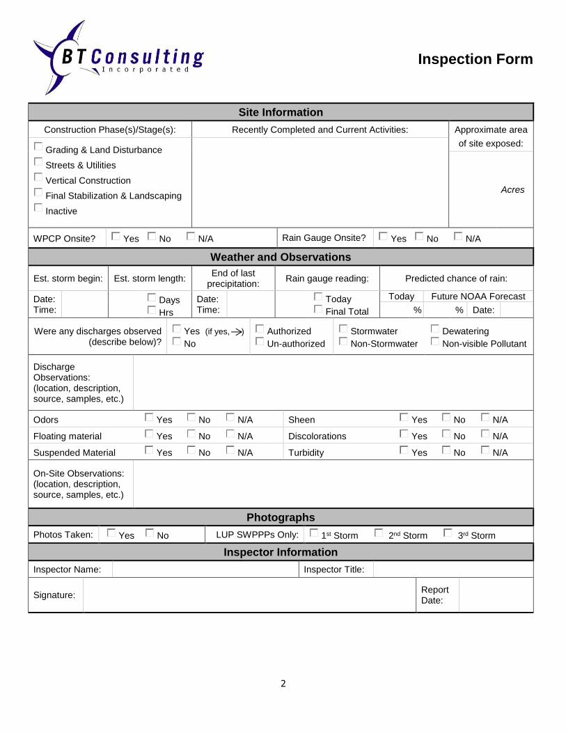
Inspection Form
2
Site Information
Construction Phase(s)/Stage(s): Recently Completed and Current Activities: Approximate area
Grading & Land Disturbance
Streets & Utilities
Vertical Construction
Final Stabilization & Landscaping
Inactive
of site exposed:
Acres
WPCP Onsite? Yes No N/A Rain Gauge Onsite? Yes No N/A
Weather and Observations
Est. storm begin: Est. storm length: End of last
precipitation: Rain gauge reading: Predicted chance of rain:
Date: Time:
Days
Hrs
Date: Time:
Today
Final Total
Today Future NOAA Forecast
% % Date:
Were any discharges observed (describe below)?
Yes (if yes, )
No
Authorized
Un-authorized
Stormwater
Non-Stormwater
Dewatering
Non-visible Pollutant
Discharge Observations: (location, description, source, samples, etc.)
Odors Yes No N/A Sheen Yes No N/A
Floating material Yes No N/A Discolorations Yes No N/A
Suspended Material Yes No N/A Turbidity Yes No N/A
On-Site Observations: (location, description, source, samples, etc.)
Photographs
Photos Taken: Yes No LUP SWPPPs Only: 1st Storm 2nd Storm 3rd Storm
Inspector Information
Inspector Name: Inspector Title:
Signature: Report Date:

Inspection Form
3
BMP Checklist
Housekeeping – Construction Materials Implemented:
Yes No N/A Action
#
Is there an inventory of products used and/or expected to be used and the end products that are produced and/or expected to be produced. Does not include materials and equipment that are designed to be outdoors?
Are loose stockpiled construction materials that are not actively being used covered or bermed? (i.e. Soil, spoils, aggregate, fly-ash, stucco, hydrated lime etc.)
Are chemicals stored in watertight containers (with appropriate secondary containment to prevent any spillage or leakage) or in a storage shed (completely enclosed)?
Is exposure of construction materials to precipitation minimized? This does not include materials and equipment that are designed to be outdoors.
Are BMPs to prevent the off-site tracking of loose construction and landscape materials implemented?
Housekeeping – Waste Management Implemented:
Yes No N/A
Action #
Is the disposal of any rinse or wash waters or materials on impervious or pervious site surfaces or into the storm drain system prevented?
Are sanitation facilities (e.g., portable toilets) contained to prevent discharges of pollutants to the storm water drainage system or receiving water?
Are sanitation facilities cleaned, replaced, and/or inspected regularly for leaks and spills?
Are waste disposal containers covered at the end of every business day and during rain events?
Are discharges from waste disposal containers to the storm water drainage system or receiving water prevented?
Is stockpiled waste material contained and securely protected from wind and rain at all times unless actively being used?
Are procedures that effectively address hazardous and nonhazardous spills implemented?
Are equipment and materials for cleanup of spills available on site and spills or leaks cleaned up immediately and disposed of properly?
Are concrete washout and other washout areas that may contain additional pollutants contained so there is no discharge into the underlying soil and onto the surrounding areas?
Housekeeping – Vehicle Storage and Maintenance Implemented:
Yes No N/A
Action #
Is oil, grease, or fuel prevented from leaking in to the ground, storm drains or surface waters?
Is all equipment or vehicles, which are to be fueled, maintained and stored placed in a designated area fitted with appropriate BMPs (Traditional Projects)?
Are leaks cleaned immediately and leaked materials disposed properly?

Inspection Form
4
Housekeeping – Landscape Materials Implemented:
Yes No N/A
Action #
Are stockpiled materials such as mulches and topsoil contained when not actively being used?
Are fertilizers and other landscape materials contained when they are not actively being used?
Is the application of any erodible landscape material discontinued within 2 days before a forecasted rain event or during periods of precipitation?
Is erodible landscape material applied at quantities and application rates according to manufacturer’s recommendations or based on written specifications by knowledgeable and experienced field personnel?
Is erodible landscape material stacked on pallets and covered or stored when not being used or applied?
Housekeeping – Air Deposition Implemented:
Yes No N/A
Action #
Is the air deposition of site materials and from site operations controlled? Particulates include, but are not limited to, sediment, nutrients, trash, metals, bacteria, oil and grease and organics.
Non-Storm Water Management Implemented:
Yes No N/A
Action #
Are measures to control all non-storm water discharges during construction implemented?
Are vehicles washed in such a manner as to prevent non-storm water discharges to surface waters or MS4 drainage systems?
Are streets cleaned in such a manner as to prevent unauthorized non-storm water discharges from reaching surface water or MS4 drainage systems?
Erosion Control Implemented:
Yes No N/A
Action #
Is effective wind erosion control implemented?
Is effective soil cover for inactive areas and all finished slopes, open space, utility backfill, and completed lots provided?
Is the use of plastic material limited when more sustainable, environmentally friendly alternatives exist? Where plastic materials are deemed necessary, the discharger shall consider the use of plastic materials resistant to solar degradation.
Sediment Controls Implemented:
Yes No N/A
Action #
Are effective perimeter controls established and maintained?
Are all construction entrances and exits stabilized to sufficiently control erosion and sediment discharges from the site?
Are appropriate erosion control BMPs (runoff control and soil stabilization) implemented in conjunction with sediment control BMPs for areas under active construction? (RL2/3 only)
Is construction activity traffic to and from the project is limited to entrances and exits that employ effective controls to prevent offsite tracking of sediment? (RL2/3 only)

Inspection Form
5
Are all storm drain inlets and perimeter controls, runoff control BMPs, and pollutant controls at entrances and exits (e.g. tire wash-off locations) maintained and protected from activities that reduce their effectiveness? (RL2/3 only)
Are all immediate access roads inspected on a daily basis? At a minimum daily (when necessary) and prior to any rain event, the discharger shall remove any sediment or other construction activity-related materials that are deposited on the roads (by vacuuming or sweeping).
Are linear sediment controls applied along the toe of the slope, face of the slope, and at the grade breaks of exposed slopes to comply with sheet flow lengths in accordance with the information below? (RL 2/3 Only)
Slope Percentage Sheet flow length not to exceed
0-25% 20 feet
25-50% 15 feet
Over 50% 10 feet
Run-on and Runoff Controls Implemented:
Yes No N/A
Action #
Is all run-on, all runoff within the site and all runoff that discharges off the site effectively managed? Run-on from offsite shall be directed away from all disturbed areas or shall collectively be in compliance with the effluent limitations in the General Permit.

Appendix F
Completed Forms