w-beam guardrail repair - atssa
TRANSCRIPT

W-BEAM GUARDRAIL REPAIR
A Guide for Highway and StreetMaintenance Personnel
November 2008

i
Notice
This document is disseminated under the sponsorship of the Department of Transportation in the interest of information exchange. The United States Government assumes no liability for its content or use thereof.
The contents of this report reflect the views of the author, who is responsible for the facts and the accuracy of the data presented herein. The contents do not necessarily reflect the official policy of the Department of Transportation.
This report does not constitute a manual, handbook, standard, specification, or regulation.
The United States Government does not endorse products or manufacurers. Trademarks or manufacturers’ names appear herein only because they are considered considered essential to the objective of this document.
i
1. Report No. FHWA FHWA-SA-08-002
2. Government Accession No. 3. Recipient’s Catalog No.
4. Title and SubtitleW-Beam Guardrail Repair: A Guide for Highway and Street Maintenance Personnel
5. Report DateNovember 20086. Performing Organization Code
7. Authors
William J. Fitzgerald, P.E.
8. Performing Organization Report No.
9. Performing Organization Name and AddressVanasse Hangen Brustlin Inc PerformTech Inc. 8300 Boone Boulevard, Suite 700 810 King StreetVienna, VA 22182-2626 Alexandria, VA 22314
10. Work Unit No.11. Contract or Grant No.DTFH61-05-D-00024
12. Sponsoring Agency Name and AddressOffice of SafetyFederal Highway AdministrationU.S. Department of Transportation1200 New Jersey Avenue, S.E.Washington, D.C. 20590
13. Type of Report and Period CoveredFinal Report
14. Sponsoring Agency Code
15. Supplementary Notes: The FHWA Office of Safety Contract Task Order Manager was Dr. Clayton Chen. The Technical Oversight Working Group included Ed Denehy-NYSDOT, Tom Nutini-Franklin Co, OH, Dennis Randolph-Calhoun Co, MI, Gary Rohrer-Washington Co, MD, and Glenn Schulte-UDOT.
16. AbstractRoadside barriers are a critical safety device as they shield motorist from what might be a more severe crash when leaving the roadway. Therefore, when damaged they need to be repaired so that they can perform this function. The purpose of this guide is to provide highway and maintenance personnel with up-to-date information on how to repair damaged W-Beam guardrail, the most frequently used barrier system. Three levels of damage are described and guidance is provided on the need and procedure for appropriate repairs. Appendices provide information on the resources (equipment, tools, crew, and time) that will be needed and forms for inspection and maintenance. This guide is an update of a document, W-Beam Guardrail Repair and Maintenance: A Guide for Local Highway and Street Maintenance Personnel, published in 1990 by FHWA.17. Key WordsW-Beam guardrail, repair, maintenance
18. Distribution StatementNo restrictions. This document is available to the public through the National Technical Information Service, Springfield, VA 22161.
19. Security Classif. (of this report)Unclassified
20. Security Classif. (of this page): Unclassified
21. No. of Pages: 54
22. Price
Form DOT F 1700.7 (8-72) Reproduction of completed pages authorized
ii iii
ACKNOWLEDGEMENTS
This guide was prepared by Vanasse Hangen Brustlin, Inc. (VHB) under FHWA Contract DTFH61-05-D-00024. Ms. Leslie Wright, Federal Highway Administration Office of Safety, was the initial Task Order Manager; she was replaced by Dr. Clayton Chen. The principal investigator and author was William J. Fitzgerald, P.E. as a consultant from PerformTech, Inc., to VHB. Technical editing was provided by Dr. Hugh McGee, P.E. and Ms. Vicki Glenn and document preparation was performed by Ms. Michelle Scism, all from VHB.
A Technical Working Oversight Group was formed to guide the preparation of this document. The members included:
Edward Denehy, New York State Department of hTransportationThomas Nutini, Franklin County (OH) Engineer’s hOfficeDennis Randolph, P.E., Calhoun County (MI) Road hCommissionGary Rohrer, P.E., Washington County (MD) Public hWorks DepartmentGlenn Schulte, Utah Department of Transportation h
ii iii
TABLE OF CONTENTS
I. INTRODUCTION: INTENT AND CONTENT ............. 1II . IDENTIFY PROBLEMS AND PLAN APPROPRIATE
ACTION ................................................................................ 3ASSESS DAMAGE EXTENT AND REPAIR ........................ 4STANDARD SECTION .............................................. 5
Damage Examples ............................................. 6Properly Repaired Standard Section ....................... 7
TRANSITION SECTION .......................................... 10Damage Examples ........................................... 10Properly Repaired Transition Sections .................. 11
END TREATMENT SECTION .................................... 13Damage Examples ........................................... 14Properly Repaired/Replaced End Treatment ........... 16
III . REPAIR SEQUENCE GUIDANCE ................................. 22STANDARD AND TRANSITION SECTIONS .................... 23END TREATMENT SECTION .................................... 26
IV. REPAIR RECORD .............................................................. 29 REFERENCES ..................................................................... 30 APPENDIX A: ESTIMATING RESOURCES FOR
W-BEAM GUARDRAIL REPAIR ................................... 31APPENDIX B: VIRGINIA DOT REPAIR GUIDANCE ...................................................................... 42APPENDIX C: MAINTENANCE GUIDANCE ............ 47APPENDIX D: DESCRIPTION OF CLEAR ZONE .... 52

1

1
I. INTRODUCTION: INTENT AND CONTENT
Ideally, highways should be designed so there is no need for roadside barriers; unfortunately, this is seldom practical. Bridge piers, steep side slopes, non-breakaway sign or luminaire (street light) posts, or other similar features along the road create potential dangers to drivers who leave the roadway. Because barriers themselves are potential hazards, use them only when necessary to shield a condition that could be significantly more hazardous. For example, crews may be able to modify a non-traversable, potentially dangerous drainage inlet to be safely traversable, making installation of a barrier unnecessary. Should the potential hazard be a steep embankment, a bridge pier, or a large sign support, installing a barrier may be the best option for preventing serious injury or fatality.
Deciding whether to install barrier can be a complex decision. Guidance on when and where to install a barrier can be found in the Roadside Design Guide (see reference list). However, once a barrier is installed, road crews must maintain it and repair it to ensure it functions as intended.
This guide focuses on how to repair (not design) the most widely used barrier—the strong post W-beam guardrail identified as SGR-04 in the Standardized Highway Barrier Hardware Guide. (The term guardrail, and in some states guiderail, is commonly used either for just W-beam barriers or for barriers in general; for future use in this guide, the term W-beam guardrail will refer to the strong post W-beam barrier system.) The standard strong post W-beam guardrail consists of a W-beam rail element and strong posts (wood or steel) spaced at 6 ft 3 in with the rail blocked out from the posts. Although the focus is the strong post system, much of the guidance that is provided for the repair of the strong post design can apply to the weak post design as well.
Strong post W-beam guardrail with wood block and metal post.

2 3
This guide is structured around the three sections of a guardrail that have variations in design to serve their purposes:
Standard h section−the main section that shields the obstacle.Transition h section−which applies when the guardrail ties into a bridge rail or other barrier system. Terminal (or End Treatment h ) section−the initial section at the upstream (beginning) and downstream (end).
Standard sections of roadside barriers. (Source: Roadside Design Guide)
The next chapter identifies three levels of damage resulting from impacts into each section and suggests corrective action. Chapter III provides basic guidance on repair sequence and Chapter IV discusses record keeping. Appendix A addresses estimating parts and materials and identifying resources (work crews and equipment) needed for typical repair work and includes two examples of damage inspection reports and a tool for estimating the radius of curved guardrail elements. Appendix B provides one State’s guardrail repair guidelines. Although this guide is for guardrail repair, Appendix C provides guidance for maintenance activities that improve the likelihood that barriers of all types will perform as intended. Finally, Appendix D provides a description of the clear zone, an important safety feature of all roads. References are found after Chapter IV.

2 3
II. IDENTIFY PROBLEMS AND PLAN APPROPRIATE ACTION
Road agencies can learn of damaged guardrail from several sources, an accident report is the most obvious. However, as many guardrail impacts are drive-away situations, maintenance (or other highway) personnel can identify damage that may not be obvious to the casual observer, but that could keep the guardrail from performing as intended. Once the agency receives notice of damage, make an on-site review of the damage. The first priority of a review is to determine whether the barrier can be removed—by eliminating the hazard it was intended to shield. This is seldom an option, but do not lose the opportunity to improve the roadside safety. If the barrier is to remain, then the review objective is to determine the extent of the damage, what repairs to make, and when to make them.
Three categories of functionality can be used to describe the extent of damage:
Guardrail is no longer reasonably functional.1. Guardrail should function adequately under a majority 2. of impacts.Damage should not affect the guardrail’s ability to 3. perform.
Each agency must make a risk assessment about the timing of repair for each different category of functionality. The assessment would include, among other factors, agency resources (within its overall mission), hazard exposure (how likely is it the guardrail will be hit again), and hazard severity. It is important that each agency develop guidance for when to make repairs.
4 5
ASSESS DAMAGE EXTENT AND REPAIR
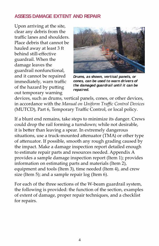
Upon arriving at the site, clear any debris from the traffic lanes and shoulders. Place debris that cannot be hauled away at least 3 ft behind still-effective guardrail. When the damage leaves the guardrail nonfunctional, and it cannot be repaired immediately, warn traffic of the hazard by putting out temporary warning devices, such as drums, vertical panels, cones, or other devices, in accordance with the Manual on Uniform Traffic Control Devices (MUTCD), Part 6, Temporary Traffic Control, or local policy.
If a blunt end remains, take steps to minimize its danger. Crews could drop the rail forming a turndown; while not desirable, it is better than leaving a spear. In extremely dangerous situations, use a truck-mounted attenuator (TMA) or other type of attenuator. If possible, smooth any rough grading caused by the impact. Make a damage inspection report detailed enough to estimate repair parts and resources needed. Appendix A provides a sample damage inspection report (Item 1); provides information on estimating parts and materials (Item 2), equipment and tools (Item 3), time needed (Item 4), and crew size (Item 5); and a sample repair log (Item 6).
For each of the three sections of the W-beam guardrail system, the following is provided: the function of the section, examples of extent of damage, proper repair techniques, and a checklist for repairs.
Drums, as shown, vertical panels, or cones, can be used to warn drivers of the damaged guardrail until it can be repaired.

4 5
STANDARD SECTION
The function of the standard W-beam section is to prevent penetration by a vehicle, either through, over, or under the W-beam and to smoothly redirect the vehicle. You can use the chart below to determine the functionality category based upon the damage to the standard section of the W-beam guardrail.
STANDARD SECTION OF W-BEAMEXTENT OF DAMAGE FUNCTIONALITY
RAIL ELEMENT SEPARATED 1RAIL ELEMENT TORN 1TOP OF RAIL HEIGHT < 24” 1
RAIL ELEMENTS INTACTFULL SPLICESTOP OF RAIL HEIGHT ≥25”*
AMOUNT OUT OF ALIGNMENT
AMOUNT OF BROKEN/BENT OR SEPARATED POSTS
3<6”
01-2 2≥3 1
6” – 12” 0-2 2≥3 1
≥18” NOT APPLICABLE 1* Guardrail less than 26” should be considered for replacement. FUNCTIONALITY CATEGORIES 1 Guardrail no longer reasonably functional 2 Guardrail should function adequately under a majority of impacts 3 Should not impair the guardrail’s ability to perform
In narrative format, this chart shows: Functionality category 1 applies to any damage where the rail element is separated or torn, or the rail height is less than 24 inches. In addition, category 1 applies if (1) there are three or more broken, bent, or separated posts and the amount out of alignment is less than 12 inches, or (2) if the amount out of alignment is equal to or greater than 18 inches regardless of post damage. Functionality category 2 applies if the guardrail is out of alignment no more than 12 inches and no more than two broken, bent, or separated posts. Functionality category 3 applies only if the guardrail has no damage other than being out of alignment by less than 6 inches.

6 7
Damage Examples
1. Damage: Guardrail no longer reasonably functional.
W-beam element is separated completely.
W-beam element is torn.
2. Damage: Guardrail should function adequately under a majority of impacts.
Rail is bent/pushed out of line less than 12 inches — rail element is intact (no tears and full splices).*
One or two posts are broken/bent over and separated from the rail — rail element is intact (no tears and full splices).*
Rail is bent/pushed more than 18 inches out of line, and/or became less than 24 inches high, or three or more posts are broken/bent over and separated from the rail.*

6 7
3. Damage: Should not impair the guardrail’s ability to perform.
*This is the best guidance currently available. An NCHRP study is under way to determine the level of damage that should not affect barrier functionality.
Properly Repaired Standard Section
The primary mechanism enabling guardrail to redirect a vehicle is tension developed in the rail element. Therefore, all repairs must ensure that full-tension capability is reestablished. The strong posts contribute to smooth redirection by limiting the amount of deflection and providing consistent stiffness along the rail to prevent pocketing. Repair all posts to a condition enabling them to perform their function.
A second critical element of functional W-beam is proper height. Full-scale tests show that 25-in-high W-beam (measured to the top of the rail element) will not contain a design impact (a 4,400-lb pick-up truck at 62 mi/h and a 25° impact angle).
If the length of damaged W-beam is significant, then repair the barrier to meet the current standard for height. For short sections (one or two panels) of repair, it generally is not practical to adjust the current height. When the whole run of the W-beam guardrail is substantially (3 inches or more) below the current standard (and is not repaired at this time), report the situation to management to ensure it is included in future W-beam upgrade projects.
Rail is bent/pushed out of line less than 6 inches — rail element is intact (no tears and full splices; guardrail height is minimum 26 inches).*

8 9
Ensure all repaired guardrail meets your agency’s current standard (except related to height, as discussed above). For repair only, use posts of a material different than the existing material only when it is impractical to obtain like-material posts. The length of W-beam to be repaired should depend on the total length of barrier and the extent of damage. If damage is severe and either the length of the whole installation is short or the amount of damage is greater than a certain percent of the total length, then bring the total system to current agency standard (including height). Values for these two criteria are arbitrary and should be set by the agency. Appendix B provides an example of one State’s criteria (note: the height criteria included in this example do not conform to the guidance in this booklet). Typical values are 100 to 200 ft to define short length and 50 percent to define portion of total length needing repair.
There is an exception to the recommendation in the previous paragraph to meet current agency standards: When existing steel post/steel block out W-beam needs repair, and it is not against agency policy, crews can use (or install) steel blocks when the posted speed is 45 mi/h or less. Back-up plates (1-ft-long pieces of W-beam rail) are required at nonsplice rail-to-post connections, and there should be no washers under any rail-to-post bolt head.

8 9
Repaired W-beam Checklist
1. Tension capability is intact:a. No tears.b. Eight ⅝-in splice bolts in each rail connection.c. No rail subjected to a cutting torch is reused; any new holes are
drilled.
2. Height is according to standard.
3. Posts are intact and firmly bedded in ground. Use a longer post (7 ft+) in front of a fill slope when there is less than 1 ft of relatively flat ground behind the post.
4. No washers under rail-to-post bolt head.
5. Available deflection distance in back of W-beam to a rigid vertical object (W-beam deflects as it develops tension — 3 ft is the standard distance provided; if 3 ft is not available, then add posts and/or nest rail to stiffen the system).
6. Lap rail elements in the direction of traffic (upstream {approach} rail is in front of downstream {leave} rail).
7. For wood block on wood posts, use toenails to restrain blocks from rotating, preferably one on each side of the block, 2 inches from the top or bottom.
8. Guardrail-mounted delineators in damaged section replaced. If no guardrail-mounted delineators previously existed, install delineators per MUTCD and/or highway agency policy.
(Items 3 and 5 are most applicable for high-speed facilities and could be less restrictive for lower speed facilities.)

10 11
TRANSITION SECTION
The function of the transition section is to gradually and smoothly stiffen a semi-flexible W-beam section having a 3-ft dynamic deflection as it attaches to a rigid, non-deflecting object such as a concrete bridge parapet or (anchored) concrete barrier to prevent pocketing.
Damage Examples
1. Damage: Transition no longer reasonably functional.
2. Damage: Transition should function adequately under a majority of impacts.
W-beam element is not attached to rigid object.
W-beam is severely pocketed in advance of the rigid object.
Rail is flattened and bent / pushed out of line less than 12 inches; rail element is intact and securely attached to the rigid object.

10 11
3. Damage: Should not impair the transition’s ability to perform.
Properly Repaired Transition Sections
The traditional transition to concrete bridge parapets constructed before the 1990s used 3-ft, 1½-in post spacing for 25 ft in advance of the connection to the rigid object. When tested at a high speed, this design failed miserably.
Many designs meet the current testing requirements for high-speed facilities; for low-speed facilities, the Texas DOT has developed a more economical design1. All accepted transition designs incorporate four features:
Foremost is a strong tension connection between the hW-beam and the rigid object. More and/or larger posts close to the rigid object. hA nested rail element for the last 12½ ft. hSome means to prevent wheel snagging, such as a rub hrail or curbing.
The whole treatment is typically 25 ft long but could be 18½ or 31½ ft. Although metal bridge railings may not be as rigid as concrete parapets, follow the same concept of a strong tension connection, gradual stiffening, and snag prevention.
1 Design can be seen at ftp://ftp.dot.state.tx.us/pub/txdot-info/cmd/cserve/stan-dard/roadway/mbgtl205.pdf
Rail is flattened / pushed out of line less than 6 inches; rail element is intact and securely attached to the rigid object.

12 13
Repair transitions that did not previously contain all the above features to current standards; if that is not practical, then provide the above features on high-type facilities. (A rail-to-post bolt is not required at the locations of any extra posts when an installation is not to a standard.) On lower type facilities, it may not be practical to include all of the features to their full extent, but all repairs should have a strong tension connection. Repairs should be conducted to correct the connection even if a transition is outside the normal limits of repair within a W-beam run or if it does not contain a strong tension connection.
Repaired Transition Checklist
1. Tension capability is intact:
a. No tears in rail elements.
b. Minimum of four ⅞-in-high strength bolts/threaded rods in connection to rigid object — ensure the bolt heads or nuts on the threaded rods protrude no more than ¾ inches from the face of the connection plate.
c. All splices are intact (eight splice bolts in each rail connection)
d. No rail subjected to a cutting torch.
2. Extra/larger posts — the last post spacing in advance of the rigid object should be 1 ft, 6¾ in.
3. Nested last rail element.
4. Rub rail or curb to prevent wheel snagging.
5. Bridge shoe lapped in the direction of the near-side traffic.
6. Damaged or knocked-down object (hazard) marker (if any) replaced on or adjacent to bridge parapet.
Traditional Transition.

12 13
END TREATMENT SECTION
The function of the end treatment is to prevent serious injury to occupant when struck on the end and provide tension for the W-beam for side (traffic face) impacts.
Over the years end treatments have developed from simply ending the W-beam run (probably with a “shovel” end section attached — with or without the end section, providing little tension but most importantly presenting a spear) to turn down systems (that provide tension and won’t spear, but that could launch a vehicle) to stand-up “safe” end treatments. The two major types of stand-up end treatments are non-energy-absorbing and energy-absorbing.
End treatments prevent serious injury either by being relatively soft for end-on impacts or using an energy-absorbing head slipped over the rail element to absorb the energy of the impacting vehicle by deforming the rail as it is forced into the head during shallow-angle, end-on impacts. For the stand-up end treatments, the tension function is provided by a cable attached to the rail element and anchored in the first post through a bearing plate and the post is placed in a foundation. Since the early 1990s, a strut ties post 1 together to post 2 to provide the needed resistance to the tension in the cable developed from a downstream impact.
Non-energy-absorbing end treatment.
Energy-absorbing end treatment.

14 15
Damage Examples
1. Damage: End treatment no longer reasonably functional.
Energy-absorbing end treatments depend on the column strength of the rail element to activate the energy-absorbing characteristic of the design. The rail element must be in a straight line to develop this strength. If there are dents in the rail element, even relatively small, near the impact head, then the system will probably not perform as desired for shallow-angle, end-on impacts. Replace the dented rail element.
End treatment partially or fully destroyed and presents a blunt end energy-absorbing system.
End treatment partially or fully destroyed and presents a blunt end Non-energy-absorbing system.
Energy-absorbing head off of rail — probably will not ride down rail but may create a spear.

14 15
2. Damage: End treatment should function adequately under a majority of impacts.
Neither the turndown nor the breakaway cable terminal (BCT) (see photos below) have been successfully crash tested for both a large vehicle (sedan or pick-up) or a small car. One should replace them with current standard hardware, even for minor damage. This is especially true for high-type facilities. Turndowns are easy to identify. The BCT looks similar to a MELT (Modified Eccentric Loader Terminal, see photo on next page), a stand-up end treatment that passed previous crash-test requirements and can be repaired when it incurs minor damage. The BCT has no strut between posts 1 and 2, standard strong posts for all posts beyond post 2, and bolts attaching the rail element to all posts.
Post 1 is broken such that full tension is not developed for downstream hits; however, the impact head should absorb most of a vehicle’s energy for shallow–angle, end-on impacts.
Turndown is obvious. Breakaway Cable Terminal (BCT)No strut between posts 1 and 2.Standard posts beyond post 2.Bolts attach rail to each post.

16 17
3. Damage: Should not impair the end treatment’s ability to perform.
Properly Repaired/Replaced End Treatment
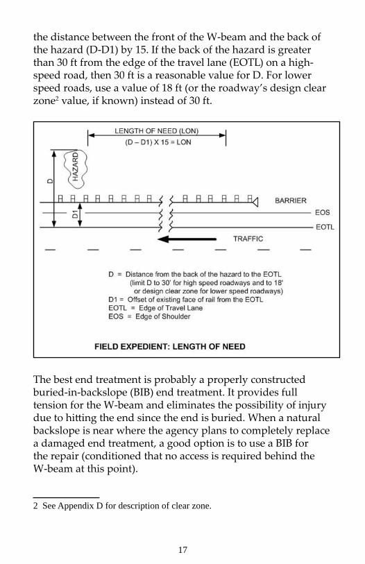
For a W-beam guardrail to adequately shield a serious hazard, the length of the W-beam guardrail must extend some distance upstream in advance of the hazard. If the W-beam guardrail is not long enough, then a vehicle can leave the roadway before it is beside the hazard and still reach the hazard the W-beam was intended to shield. This adequate distance in advance of the hazard is called the length of need (LON). Although a designer uses a special procedure to determine the LON, a simple field expedient procedure, shown in the sketch below, is to multiply
Post 1 is intact. Rail element is less than 12 inches out of line (non-energy-absorbing end treatment only).
Modified Eccentric Loader Terminal (MELT)Strut between posts 1 and 2.All weak posts within system.No rail-to-post bolts except at post 1.
16 17
the distance between the front of the W-beam and the back of the hazard (D-D1) by 15. If the back of the hazard is greater than 30 ft from the edge of the travel lane (EOTL) on a high-speed road, then 30 ft is a reasonable value for D. For lower speed roads, use a value of 18 ft (or the roadway’s design clear zone2 value, if known) instead of 30 ft.
The best end treatment is probably a properly constructed buried-in-backslope (BIB) end treatment. It provides full tension for the W-beam and eliminates the possibility of injury due to hitting the end since the end is buried. When a natural backslope is near where the agency plans to completely replace a damaged end treatment, a good option is to use a BIB for the repair (conditioned that no access is required behind the W-beam at this point).
2 See Appendix D for description of clear zone.

18 19
Examples of buried-in-backslope end treatments.
When repairing or replacing a stand-up end treatment with a new stand-up end treatment, you should provide the LON. However, in the majority of situations, it is either unavailable or impractical to provide the LON. Although the non-energy-absorbing end treatments perform well to minimize the hazard of the end of the W-beam, their softness allows the vehicle to pass through and behind the guardrail, and without adequate LON, could reach the hazard the W-beam was intended to shield. An energy-absorbing end treatment has an additional capability beyond developing tension and not causing serious injury on end-on impact: for shallow-angle, end-on hits, it can absorb much of the vehicle’s energy and either stop the vehicle within the system itself or slow the vehicle significantly such that any downstream impact should be less severe. Therefore, use energy-absorbing systems to repair or upgrade damaged end treatments if they do not have acceptable LON and satisfactory grading, as discussed below.
Many current crashworthy end treatments are proprietary and have been designed and engineered with unique details necessary to allow them to perform properly. For example, some posts in the installations have bolts connecting the rail to the post while others do not. Also, most designs have evolved to make them more effective as well as more economically competitive. Therefore, before beginning repair on these systems, or installing new as replacements, be sure you have the manufacturer’s shop drawings and installation manual for the particular model on site.

18 19
Grading: All accepted end terminals (except the BIB) were tested on flat ground. Therefore, it is best to duplicate this condition in the field so the end treatment has the best chance of performing as intended. This is generally accepted as being provided when there is 5 ft of relatively flat ground (1:10 [Vertical:Horizontal] or flatter) behind the first post of the system (and gradually tapered back to the existing cross section in advance of the end treatment), as shown below.
Recommended Grading Plan.Source: Roadside Design Guide
The grading downstream of the end treatment should be available clear zone in accordance with the LON concept describe above. Also, because the posts of the system are designed to break off or bend upon end-on hits to allow the vehicle to continue down or through the system, ensure whatever posts remain after breaking or bending extend no more than 4 inches above the ground.
The previous recommendation to use energy-absorbing end treatments is re-emphasized because the 5 ft flat grading is seldom achievable in the field.
Guidelines for the Selection of W-beam Barrier Terminals developed by FHWA, provides additional information on the selection and performance of the different currently accepted end treatments. The CD-ROM (Publication Number FHWA-SA-06-19) containing these guidelines can be obtained from the FHWA Report Center. Fax requests to (301) 577-1421 or email requests to [email protected].

20 21
The Vermont End Terminal is a relatively inexpensive end treatment that provides both tension and a “safe” impact for lower speed (≤ 45 mph) facilities: (Additional information on this end treatment is available in the AASHTO Roadside Design Guide (RDG), chapter 8). Its use is also appropriate on a higher speed facility at the approach to a STOP sign. It uses a typical cable to develop the required tension and a radius W-beam element to prevent spearing. It is also fairly easy to construct.
When an end treatment’s only function is to develop tension, such as when used at the downstream end of a run of barrier (that is outside the clear zone of opposing traffic), an economical system is to simply attach the typical cable to the last rail element and anchor the cable in the last post that uses a steel foundation tube for resistance (see photo and figure below).
Vermont End Terminal.

20 21
Repaired/Replaced End Treatment Checklist:
1. Use no interchanged parts from different manufacture’s systems for parts unique to the particular end treatment being repaired.
2. For energy-absorbing systems, place the head completely onto the rail element.
3. For energy-absorbing systems, the cable anchorage to the rail element allows the cable to release from the rail if the head slides.
4. Post 1’s top part will separate from its foundation for end-on impacts.
5. Replace any damaged posts within the end treatment that were originally breakaway or yielding posts with breakaway or yielding posts approved by the system’s manufacturer.
6. Grading provides no more than 4 inches above ground to the strut or to what will remain as a stub.
7. Bearing plate is properly oriented.
8. Cable is tightened to a taut condition; cannot lift up on the cable more than 1 inch.
9. Retroreflective object (hazard) marker in place on non-buried end treatments per highway agency policy.

22 23
III. REPAIR SEQUENCE GUIDANCE
This chapter provides guidance on how to repair W-beam guardrail sections. Some critical actions you should take before the actual repair include:
Upon notification of damage and when the damage hleaves the guardrail nonfunctional, and it cannot be repaired immediately, warn traffic of the hazard by putting out temporary warning devices in accordance with the MUTCD, such as drums, vertical panels, cones, or other devices.Contact your local Dig Safe utility protection well in hadvance of going to the site.Take enough signs and channelizing devices to the site hto properly mark the repair zone. When your agency uses an arrow board and/or a shadow truck or Truck Mounted Attenuator (TMA), be certain there is enough equipment and personnel to handle these items. Set up the Temporary Traffic Control Plan for the work harea to repair the guardrail in accordance with the MUTCD or your agency requirements.Ensure all workers wear equipment as provided by the hOccupational and Safety Administration (OSHA) or local requirements, such as safety visibility vests, safety glasses, and protective-type shoes.Ensure all equipment and procedures conform to hOSHA guidance.
The remaining portion of this chapter is divided into standard and transition sections, and end treatments

22 23
STANDARD AND TRANSITION SECTIONS
The following sequence is usually followed in repairing the standard or transition sections:
Disassemble damaged guardrail.1.
Spray the connecting bolts with penetrating oil •for easier removal. Unbolt the damaged rail-beam sections.If the elliptical shoulder is worn off the bolt, then •hold the smooth round head with vise grips to unscrew the nut. Use a torch to cut stubborn bolts. Do not torch cut rail sections to be reused.
Pull out damaged posts.2.
Steel posts can often be worked out by hand or with •a crowbar. Crews may have to use a chain and hoist to dig or pull wood posts.Slightly twisted steel posts still firmly in the ground •can often be straightened in place by pulling with a chain attached to a truck. Provide traffic control warning if the truck’s operation encroaches on the traveled roadway. Use a crowbar to pull posts only pushed off-line back into line.
If necessary, use a grader to reshape the shoulder area 3. and recompact the soil for posts. If placing new post(s), then rework the area before installing the post(s), if practical.Set up a stringline to position posts at the proper 4. height, alignment, and spacing. If repairing more than two panels, then set the W-beam to the standard height. It is relatively easy to create up to a 4-in change in height over one panel length. (When the rail height is not adjusted and is 3 or more inches below standard, report it to your maintenance supervisor.) Mark the stringline for the proper post height and alignment. Use a tape or a measuring stick to mark the proper post spacing.

24 25
Drill or dig holes for the posts, if necessary.5. Set or drive posts to the proper height.6. Backfill and compact the soil around the posts.7. Check post alignment and height. Correct any major 8. deviations.Starting downstream and working backwards, loosely 9. hang new rail sections and offset blocks. Lap rail elements in the direction of traffic. In general, do not use washers under the bolt heads of the rail-to-post bolts. When using steel posts with steel offset blocks, a back-up plate is needed at the intermediate posts (the posts between the rail splices).If necessary, use a drift pin to line up 10. the holes for bolting.Make sure all 8 bolts are in place in 11. each splice connection.Leave all connections finger tight to allow for 12. lengthwise adjustment after all sections are installed.Final assembly — when all rail is hung, go back and 13. snugly tighten all bolts. There is no need to overtighten.Cleanup — smooth out the shoulder and slope 14. approaching the guardrail so the next vehicle to run into it has a smooth path.Install guardrail-mounted delineators and, if 15. appropriate, object hazard markers.
Make a final inspection before leaving the site. Complete the suggested checklist at each location to document the work.

24 25
Completed Work Inspection Checklist (Standard Section and Transitions)
____Do all splices have eight bolts; have all bolts—both splice and rail-to-post—been checked to see that each is tightened snug?
____Is a blockout used on each post?
____ Guardrail height was checked to make sure it is correct and did not shift up or down out of tolerance during the final assembly?
____ Deflection distance is provided from any vertical, rigid object or the W-beam system appropriately stiffened?
____ Adequate soil backing is provided behind the posts; if not, are longer posts used?
____ A nail(s) is driven in each wood blockout on wood posts to toenail the block to the post to prevent rotation?
____ If steel blockouts are retained, does each steel post between the splices have a back-up plate behind the rail element?
____ Were all washers between the bolt head and the rail element removed (unless required) from the repaired W-beam length?
____ Is the lap of the rail elements correct?
____ Are guardrail-mounted delineators located properly on the guardrail?
For repair including transitions:
____ Are the four (minimum) ⅞-inch-high strength bolts properly anchored and NOT protruding significantly in front?
____ Is the last rail element nested?
____ Are there enough/properly sized posts adjacent to the rigid object?
____ Has a means to prevent wheel snagging (rub rail or curbing) been applied, if necessary?
____ Is the lap of the bridge shoe correct?
Date repair completed: _________________________
Repair completion inspected by:______________________________ (Signed)

26 27
END TREATMENT SECTION
The following steps are suggested for end treatments:
Remove the damaged hardware as described for the 1. standard W-beam section. If the end treatment is an energy-absorbing type, and the impact head is pushed down the rail element, cut off the deformed steel and pull off the head — do not cut the rail or unbolt the splice downstream of the head until the head is removed. Guidance for determining whether an impacted head can be reused: Reuse it when there is obviously no damage; replace it if questionable.For damage meeting criteria that requires replacing the 2. whole end treatment, check the LON to determine if appropriate W-beam length is available to adequately shield the hazard. Add any standard W-beam as deemed necessary before installing the new end treatment. Provide the necessary grading platform prior to constructing any end treatments.
Because of the many possible options that repair/replace damaged end treatments, it is virtually impossible to give detailed instructions for their treatment. However, two items must be discussed.
Many different types of posts are used in the different end treatments, both generic and proprietary. Examples are:
Weakened wood posts, called CRT posts, that are 6 ft hlong and have 3½-in-diameter holes drilled at ground line and 16 inches below the ground. Short wood posts 45 inches long with a 2½-in hole, hwhich slip into steel foundation tubes driven in the ground —foundation tubes have different lengths and may or may not have soil plates attached to them. Steel posts that come in two parts and are attached by hbolts at the ground line.

26 27
Steel posts having two parts that are h plug welded together.Steel posts that look like standard 6-ft steel posts, but hhave four holes in the flanges at ground line; and more.
Because of this variety, make a detailed inspection of the type in the existing installation. Replace damaged posts in an installation that is only to be partially repaired with the same type of the original posts. However, several manufacturers have developed steel posts that facilitate repair — be sure to check with each manufacturer for approved variations and mixing of post types before using a post type different than the damaged one(s).
To repair or replace any proprietary types of end treatments, it is imperative that crews have the manufacturer’s shop drawings and installation manual on site during repairs. Installation manuals also contain guidance for repairing damaged installations and can be used on generic installations as well, such as removing the wood stub left in a foundation tube.

28 29
Completed Work Inspection Checklist (End Treatments)
___Is the anchor cable properly attached to the rail element?
____Is the grading correct under the appropriate standard (including 4-in stub height requirement for post foundations and for struts)?
____ Will post 1 separate from its base on end-on impacts?
____ Has the LON been reviewed for appropriateness?
____ For energy-absorbing end treatments, is the rail element inserted deeply inside the head, and is there NO bolt connecting the rail to post 1?
____ Is the bearing plate properly oriented and restrained from turning?
____ Are all rail-to-post bolts located according to the manufacturer’s drawings?
____ Is the anchor cable taut?
____ Are all wood block-outs on wood posts properly toenailed to prevent rotation?
____ Is the object (hazard) marker installed?
Date repair completed: _________________________
Repair completion inspected by:
______________________________ (Signed)
28 29
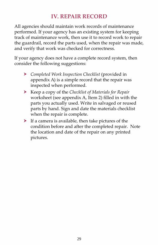
IV. REPAIR RECORD
All agencies should maintain work records of maintenance performed. If your agency has an existing system for keeping track of maintenance work, then use it to record work to repair the guardrail, record the parts used, when the repair was made, and verify that work was checked for correctness.
If your agency does not have a complete record system, then consider the following suggestions:
Completed Work Inspection Checklist h (provided in appendix A) is a simple record that the repair was inspected when performed.Keep a copy of the h Checklist of Materials for Repair worksheet (see appendix A, Item 2) filled in with the parts you actually used. Write in salvaged or reused parts by hand. Sign and date the materials checklist when the repair is complete.If a camera is available, then take pictures of the hcondition before and after the completed repair. Note the location and date of the repair on any printed pictures.

30 31
REFERENCES
Manual on Uniform Traffic Control Devices (MUTCD): 1. http://mutcd.fhwa.dot.gov/
Standardized Highway Barrier Hardware Guide: 2. http://aashtotf13.tamu.edu/index.htm
FHWA-accepted roadside hardware: 3. http://safety.fhwa.dot.gov/roadway_dept/road_hardware/index.htm
End-treatment manufacturers: 4. Road Systems Inc: http://www.roadsystems.com/ Trinity Industries: http://www.highwayguardrail.com/
AASHTO Roadside Design Guide: 5. https://bookstore.transportation.org/item_details.aspx?id=1172
Guidelines for the Selection of W-beam Barrier 6. Terminals: FHWA Publication FHWA-SA-06-19, December 2006 (available from FHWA Report Center; request by email at [email protected])

30 31
APPENDIX A: ESTIMATING RESOURCES FOR W-BEAM GUARDRAIL REPAIR
1. EXAMPLE OF DAMAGE INSPECTION REPORT
Damage inspection Report – New York State DOT
Calculating Guardrail Radius (to complete form above)

32 33
2. ESTIMATING PARTS AND MATERIALS FOR STANDARD SECTION W-BEAM REPAIR
Typical elements of the W-beam guardrail (a standard 12-ft, 6-in rail length is assumed; if an agency allows a 25-ft rail length, then make appropriate adjustments) include the following:
12-ft, 6-in steel W-beam rail sections (matching existing hmaterial – gauge, galvanizing, treated, or “rusting steel”, etc.).Eight each ⅝-in by 1¼-in galvanized buttonhead bolts hwith recessed nuts for each rail splice.One each, ⅝-in rail-to-post galvanized buttonhead bolt hwith round washer and recessed nut for fastening rail to post; length varies depending on the type of offset block and type of post:
Wood block to wood post: 18 inches.1. Wood or approved block to steel post: 10 inches.2. Steel block to steel post: 2 inches (no washer on 3. back + 2 each —1½-in bolts to connect blockout to post).
One each, 1-ft, 2-in wood offset block for wood post or happroved offset block for steel post, to space the rail away from the post to minimize snagging.6-ft, 0-in posts. To agency standard (6 by 8 or 8 by 8 hwood posts or W6 by 8.5 or W6 by 9 steel posts.12-in galvanized W-beam backup plate at intermediate hsteel post locations with steel offset block for placing behind rail where no rail splice occurs.10d to 16d galvanized nail(s) to keep wood offset block hfrom rotating on wood post.

32 33
---------- TrafficW-Beam with Wood Offset Block on Wood Post
---------- TrafficW-Beam with Approved Offset Block on Steel Post

34 35
---------- TrafficW-Beam with Steel Offset Block on Steel Post
Checklist of Materials for Repair
Item Compute Numberneeded
W-beam galvanized steel rail sections12-ft, 6-in-long, desirably punched @ 3ft, 1½ -in spacing
Tally # of damaged Sections @ 12ft, 6 in
⅝-in by 1¼ -in-long splice bolts with nuts (# sections x 8) + 8⅝–in rail-to-post bolts with recess nuts and round washers for connecting rail to post and block
(# sections x 2) + 1
6-ft , 0-in posts* (# sections x 2) + 1Offset blocks Same as # of postsFor wood block on wood post:10 16d galvanized nails (preferably two per offset block)
2 x # of offset blocks
For steel block on steel post:12-in W-beam back-up plate
Same as # of sections
For steel block on steel post:⅝ -in by 1½ -in hex-head bolts to connect block
2 x # of offset blocks
Guardrail-mounted delineators Same as # of sections
Object (hazard) marker 1 for each end* If there is not adequate soil support behind the posts, use 7 ft or longer posts.

34 35
This list indicates an exact number of parts. Be sure to take into account additional numbers of each part for damage, loss, etc.
A detailed list like this is not appropriate for end-treatment repair/replacement. The proprietary manufacturers’ installation manuals contain bills of material for each model of their products. Check these when conducting a complete replacement installation or for the appropriate quantities based on the amount of repair/replacement.
3. ESTIMATING EQUIPMENT AND TOOLS
The following is a listing of equipment and tools that will be needed for guardrail repair. There are two lists: the first is from a typical state highway agency truck; and the second is from a typical guardrail contractor truck. Make sure you comply with OSHA or your local regulations when using this equipment.
EXAMPLE 1– A TYPICAL STATE HIGHWAY AGENCY TRUCK
Supervisor Truck Supplies⅜-in drive ratchet and socket set
(end treatments have small nuts and bolts)
¾-in drive ratchet and socket set (bridge connections and anchor terminals)
½-in drive ratchet and socket set with 3-in and 10-in extensions
7/16 to 1⅛” sockets
5 to 1¼” bell sockets 4-in to ½-in drive socketsFour - splice pins, 2 pinch bars / pry
barsOpen end and box wrench set 5/16
to 1¼ inchTwo ½-in impact wrench Two 5/16-in impact socketsTwo 1⅛-in impact socket Three 1¼-in impact bell socketTwo 1¼-in Impact Deep Bell SocketOne 15-in adjustable wrench One 20-in adjustable wrenchFour vise grip pliers Two 4-lb hammersOne 18 lb sledge hammer One 10-lb sledge hammerTwo flat shovels Two round shovelsTwo post hole digger Two digging bars
36 37
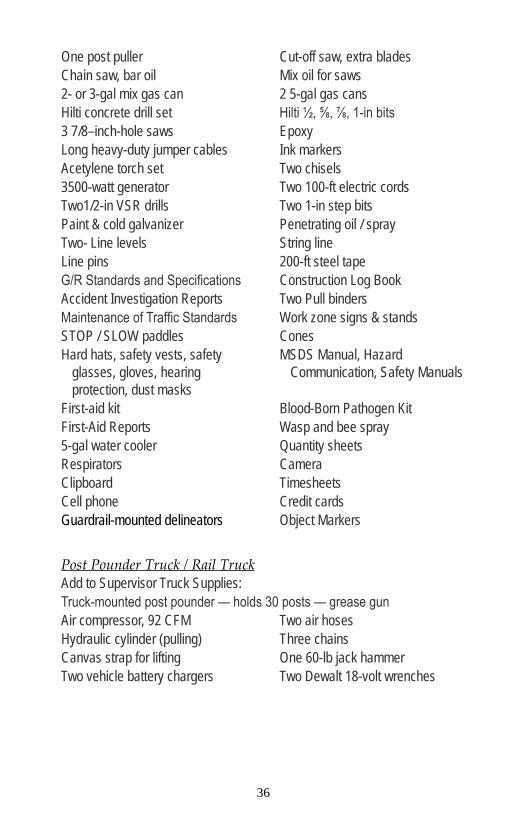
One post puller Cut-off saw, extra bladesChain saw, bar oil Mix oil for saws2- or 3-gal mix gas can 2 5-gal gas cansHilti concrete drill set Hilti ½, ⅝, ⅞, 1-in bits3 7/8–inch-hole saws EpoxyLong heavy-duty jumper cables Ink markersAcetylene torch set Two chisels3500-watt generator Two 100-ft electric cordsTwo1/2-in VSR drills Two 1-in step bitsPaint & cold galvanizer Penetrating oil / sprayTwo- Line levels String lineLine pins 200-ft steel tapeG/R Standards and Specifications Construction Log BookAccident Investigation Reports Two Pull bindersMaintenance of Traffic Standards Work zone signs & standsSTOP / SLOW paddles ConesHard hats, safety vests, safety
glasses, gloves, hearing protection, dust masks
MSDS Manual, Hazard Communication, Safety Manuals
First-aid kit Blood-Born Pathogen KitFirst-Aid Reports Wasp and bee spray5-gal water cooler Quantity sheetsRespirators CameraClipboard TimesheetsCell phone Credit cardsGuardrail-mounted delineators Object Markers
Post Pounder Truck / Rail TruckAdd to Supervisor Truck Supplies:Truck-mounted post pounder — holds 30 posts — grease gunAir compressor, 92 CFM Two air hosesHydraulic cylinder (pulling) Three chainsCanvas strap for lifting One 60-lb jack hammerTwo vehicle battery chargers Two Dewalt 18-volt wrenches

36 37
EXAMPLE 2– A TYPICAL GUARDRAIL CONTRACTOR REPAIR TRUCK
Foreman Truck Supplies⅜-in drive ratchet and socket set (end treatments have small nuts and bolts)¾-in drive ratchet and socket set (bridge connections and anchor terminals)½-in drive ratchet and socket set with 3” and 10-in extensions 7/16-in to at least 1⅛inch sockets One 20-in adjustable wrenchFive 1¼-in bell sockets 110-lb sledge hammer4½-in drive sockets 118-lb sledge hammerFour splice pins 115-in adjustable wrenchFour vise grip pliers Combo open end and box wrench
set 5/16 to 1¼ inchTwo 4lb. hammersPost puller Chain sawTwo flat shovels Cut-off sawTwo round shovels Saw bladesTwo digging bars Mix oil for sawsTwo- post-hole diggers Bar oilLong, heavy-duty jumper cables Two or three gallon mix gas cansTwo 5-gal gas cans Acetylene Torch SetInk markers 3500-watt generatorTwo 100-ft electric cord Two ½-in VSR drillsTwo 1-in step bits Three ⅞-in hole sawsTwo ½-in impact wrenches Two ½-in impact wrenchesTwo ½-in impact wrenches Four swivel socketsTwo 5/16-in impact sockets Two 1⅛-in impact socketThree 1¼-in impact bell socket Two 1¼-in impact deep bell socketsHILTI concrete drill set with bits ½,
⅝, ⅞, 1 inchClipboard, time sheets, quantity
sheets Epoxy Dust maskLine levels Construction Log BookLine pins G/R Standards and SpecificationsString line Cell phoneCredit cards Paint and cold galvanizing sprayAccident Investigation Reports Two pull bindersCamera Proper work zone signs & stands200-ft steel tape STOP / SLOW paddles / conesFirst-aid kit Blood-born pathogen kit

38 39
First-Aid Reports M.O.T. Standards5 gal water cooler Penetrating oil / sprayWasp and bee spray Object MarkersGuardrail-mounted delineatorsMSDS manual, hazard communication, safety manualsHard hats, safety vests, safety glasses, gloves, hearing protection
4. ESTIMATING TIME NEEDED FOR REPAIR
General guidelines:
Include travel time to and from the repair site when 1. this is a maintenance activity scheduled from a central garage.Plan about 30 to 45 minutes to place the traffic control 2. devices. It will take about the same time to gather the control devices after repair work is completed.Allow 30 minutes for final inspection of guardrail after 3. finishing the repair and for recording the repair job.The time needed to make ANY repair depends on 4. the experience and skill of the crew. The number of workers for the job and the amount of power-assisted tools available will also affect the time required.
Repairing cosmetic damage to guardrail installations--Should your agency want to repair the very minor type of damage mentioned earlier in this handbook, the actual repair (which may only be painting or minor straightening of a dented rail) should not require more than 30 minutes to 1 hour.
Repairing damage that still permits the guardrail to function When the inspection of the damage at the site indicates:
Only a few posts are broken. hOnly a few posts are pushed badly off line. hA rail is bent out of line less than 18 inches. h

38 39
Or other conditions exist that permit routine scheduling of the repair (rather than emergency repair), plan for 1 to 2 hours of repair time, plus traffic control, inspection, and recording.
Repairing major damage requiring prompt attention--When the guardrail damage is extensive, such as four or more posts are knocked out or several rail beam sections are broken, plan on one half day time requirement, including the traffic control setup, inspection, and recording.
FOR AGENCIES WITH MAINTENANCE MANAGEMENT SYSTEMS THAT GIVE A MORE DETAILED TIME BREAKDOWN, USE THAT TO ESTIMATE TIME.
5. ESTIMATING CREW SIZE
The crew size will depend upon the extent of the damage and the needs for traffic control. Two workers and a person in charge should be enough to repair minor damage where the guardrail is allowed to remain assuming the guardrail would function satisfactorily while the repair was scheduled. This assumes the work involves only a few posts or rail beam sections. When four or more posts are involved, or more than two rail beam sections are to be replaced, expect to need a crew of four. If a wide range of power-assisted tools is available, then a crew of three should work well.
Traffic control crew needs are as follows:
If no person is to be assigned to flag traffic through 1. the repair work zone, then no additional workers are needed. Workers repairing the rail can place and collect the traffic control devices. There can be situations causing short-term encroachment on the road to move equipment or to make brief repairs. Provide warning to traffic in such cases.Assign one worker as a flagger when the traffic cones or 2. temporary barricades around the repair site restrict the road or street to alternating one-way traffic. USE ONE

40 41
FLAGGER WHEN THAT WORKER CAN CLEARLY SEE TRAFFIC APPROACHING THE REPAIR SITE FROM BOTH DIRECTIONS AND THE FLAGGER SIGNAL CAN BE SEEN BY DRIVERS WELL IN ADVANCE OF THE REQUIRED STOP POINT.Assign two workers as flaggers for any other work 3. zone conditions where traffic cones or barricades create alternating one-way traffic flow around the repair.
IF YOUR MAINTENANCE MANAGEMENT SYSTEM GIVES MORE DETAILED CREW SIZE INFORMATION BY WORK TASK FOR GUARDRAIL REPAIR, THEN USE THAT CREW SIZE ESTIMATE.

40 41
6. EXAMPLE W-BEAM GUARDRAIL REPAIR LOG
W-beam guardrail repair log

42 43
APPENDIX B: VIRGINIA DOT REPAIR GUIDANCE
The following Instructional and Informational Memorandum can be found at: http://www.extranet.vdot.state.va.us/locdes/electronic%20pubs/iim/IIM220.pdf
VIRGINIA DEPARTMENT OF TRANSPORTATION
LOCATION AND DESIGN DIVISION
INSTRUCTIONAL AND INFORMATIONAL MEMORANDUM
GENERAL SUBJECT:
GUARDRAIL REPAIR, REPLACEMENT AND UPGRADE GUIDELINES
NUMBER: IIM-LD-220.2MM – 327 CD – 2003
– 4
SPECIFIC SUBJECT: DATE:
NOVEMBER 21, 2003
SUPERSEDES: IIM-LD-220.1TE - 305 CD – 2001 - 9
LOCATION AND DESIGN DIVISION APPROVAL:Mohammad Mirshahi, P.E.
Approved November 12, 2003
SCHEDULING & CONTRACT DIVISION APPROVAL:
W. Byron Coburn, Jr., P.E.Approved November 19, 2003
MOBILITY MANAGEMENT DIVISION APPROVAL:Raymond J. Khoury, P.E.
Approved November 20, 2003
ASSET MANAGEMENT DIVISION APPROVAL:James R. Smith, Jr.
Approved November 21, 2003
CURRENT REVISION
• This memorandum has been revised for clarification and emphasis in several areas.
EFFECTIVE DATE
• These instructions are effective upon receipt.

42 43
POLICY
• These instructions apply to the Repair, Replacement and Upgrade of Existing Guardrail Installations Only. New Installations SHALL be in accordance with current VDOT Standards.
• For the following situations all existing substandard guardrail systems and components shall be upgraded to the latest standard in accordance with current VDOT Road and Bridge Standards and this memorandum.
1. When located within the project limits of a construction project. When the line of rail extends outside the project limits, if more than 60% of the existing substandard line of rail lies within the project limits, then the entire run shall be replaced/upgraded as a part of that project.
2. When guardrail needs to be repaired/replaced under a maintenance project and/or contract (e.g. guardrail, pavement, etc.).
During routine maintenance projects and/or contracts of any roadway, all guardrail shall be reviewed, deficiencies identified, costs budgeted, and schedules set for replacement or upgrading to ensure that all existing guardrail meets current VDOT Standards. During these reviews if the guardrail is found to be more than 75 mm (three inches) lower or 75 mm (three inches) higher than current Standard requirements, then replacement or resetting shall be scheduled as soon as possible. For strong post guardrail (Standard GR-2) no metal blockouts are to be replaced in-kind or installed new, and no washers will be used other than those for the last 15.2 meters (50 feet) of a trailing end anchorage.
3. When located within the project limits of transportation improvements associated with permitted land development projects.
4. When any road is taken into the State roadway systems, all guardrail must comply with current Standards, and must include NCHRP 350 approved terminals and rail systems.
GUARDRAIL TERMINALS – DAMAGED AND SUBSTANDARD
• All terminals shall be installed as they were tested in accordance with NCHRP 350. Lapping of guardrail must be in the direction of traffic, per NCHRP 350 testing. DO NOT CHANGE THE DIRECTION OF THE LAPPING.
• When terminal damage occurs, a site investigation shall be made to determine whether the terminal should be repaired, replaced or eliminated. If a gap exists

44 45
between two runs of guardrail and it is approximately 60 meters (200 feet)+ , closing the gap by continuing the run of guardrail is recommended, thereby eliminating the need for a terminal. If a cut slope is within approximately 60 meters (200 feet) + longitudinal distance from the location of the terminal and is sufficient to install a Standard GR-6, the guardrail shall be extended to the cut slope and a cut slope terminal (Standard GR-6) should be used.
• If the installation site does not provide at least 22.8 meters (75 feet ) of clear run-out path in addition to the length of need required for the barrier (exclusive of the terminal), a parallel terminal (Standard GR-9) shall be used instead of a flared terminal (Standard GR-7). If an extensive amount of grading would be required for site preparation to install a flared terminal (Standard GR-7), consideration should be given to using a parallel terminal (Standard GR-9) that does not require as much site preparation.
• The site preparation for all installations shall be in accordance with current Standards.
• Before replacing a damaged or substandard terminal, the location of the existing terminal should be checked to ensure sufficient length of need has been provided in the run of guardrail to adequately shield the hazard for which it was installed. In some cases it may be necessary to extend the guardrail to better shield the hazard or to provide for a more suitable site that would not require grading.
• Breakaway Cable Terminals (BCT’s)
BCT’s had concrete footings for the first two posts, did not have the metal strut at ground level between the first two posts and all posts were not breakaway.
Completely replace BCT’s with new NCHRP 350 approved terminals whenever they are damaged or if they are within the limits of a construction or maintenance project/contract.
• Modified Eccentric Loading Terminals (MELT’s)
The MELT provides a 1.2-meter (4-foot) offset, a 1.5-meter (5-foot) flat area behind the first post and a metal strut at ground level between the first two wooden breakaway posts.
If the MELT (Standard GR-7) is improperly installed or when damage includes the nose assembly and first two posts, replace with new NCHRP 350 approved terminals (revised Standard GR-7) such as the SRT-350, FLEAT 350, REGENT or other approved NCHRP 350 product. When replacing substandard GR-7 terminals, make sure that the section of rail

44 45
and posts adjoining the new terminal installation is at the proper height.
• Strong Post Turned-down Terminals (Std. GR-5’s)
All turned-down strong post terminals (run-on locations) should have already been removed from roadways on the National Highway System. Any that have not been removed shall be removed immediately.
When these terminals that may remain on non-NHS roadways are damaged, they shall be replaced with NCHRP 350 approved terminals.
• Weak Post Turned-down Terminals (Std. GR-8, Type II’s)
Since no weak post terminals have been approved in accordance with NCHRP 350 for use in run-on locations, any of these terminals that are damaged shall be replaced with NCHRP 350 approved strong post terminals incorporating the appropriate transition required between a strong post terminal and weak post guardrail (in accordance with VDOT Road and Bridge Standards), regardless of the design speed of the roadway.
Any weak post run-on terminals within the limits of a construction project, maintenance project and/or contract shall be upgraded as part of the project.
For run-off locations, turned down terminals incorporating a concrete anchor (Standard GR-8, type I or II) are acceptable, regardless of the design speed of the roadway; however, the Type I and II terminals shall be outside of the clear zone of opposing traffic on two-way roadways. This includes existing installations in locations with design speeds greater than 70 km/h (45 mph) for which new installation of weak post guardrail must be in accordance with the new approved TL-3 weak post design.
• TERMINALS BURIED IN THE CUT SLOPE (OLD STANDARD GR-6)
Existing GR-6 installations that are not NCHRP 350 compliant (in accordance with current VDOT Standards) should be evaluated to ensure the following:- Proper Height per current standards -
Where existing GR-6 Terminals were installed with the height of rail following the ground line at a height of 27” to 28”, this installation method caused the terminals to be low, both in front of and behind the ditch line. These low installations may allow an errant vehicle to vault over the top rail and go behind the guardrail, failing its intended protection from hazards.

46 47
- The end anchorage is sufficiently buried in the slope 0.3 m (min. 1 foot cover).
Repair or replacement of either of these situations shall be to current VDOT Standards.
FIXED OBJECT ATTACHMENTS (FOA’S)
• Whenever a substandard fixed object or BR-GR attachment is damaged, it shall be replaced or upgraded with current Road and Bridge Standard fixed object attachments including the nesting of the rail, shortened post spacings and rubrail.
• When substandard FOA’s or BR-GR’s exist within the limits of construction projects or when replacement is required under a guardrail maintenance project and/or contract; both FOA’s and BR-GR’s shall be upgraded or replaced in accordance with the current VDOT Road and Bridge Standard.
W-BEAM GUARDRAIL
• During NEW CONSTRUCTION, always install to the current Standard heights.
• ALL W-beam guardrail panels shall be lapped in the direction of traffic. With two-way traffic, the laps on the right side of traffic are to be in the direction of traffic or toward the downstream end.
• Any existing guardrail (GR-2, GR-8) that does not meet current VDOT Standards or is identified to be greater than 75 mm (three inches) higher or lower than the Standard for the system being used, shall be scheduled for resetting or replacement. For sections of guardrail that are longer than 60 meters (200 feet), if more than 60% of the entire run has been damaged, or does not meet current Standards, the entire run shall be replaced with current Standards. If less than 60% of the entire run has been damaged, the damaged section should be replaced with current Standards.
• Weak post W-beam Guardrail (Std. GR-8)
When substandard GR-8 is damaged, the extent of damage should govern repair/replacement. If the total run of guardrail is 60 meters (200 feet) or less, the entire run shall be replaced with the latest GR-8 design (which meets NCHRP 350 Test Level 3 criteria) or if the particular site conditions are appropriate a Standard GR-2 or GR-3 system can be used.
For substandard sections of GR-8 guardrail that are longer than 60 meters (200 feet), if more than 60% of the entire run has been damaged, or does not meet current Standards, the entire run shall be replaced with the latest GR-8 design

46 47
or if the particular site conditions are appropriate a Standard GR-2 or GR-3 system can be used.
If less than 60% of the entire run has been damaged, the damaged section should be replaced with the latest GR-8 design or if the particular site conditions are appropriate a Standard GR-2 system can be used.
When either of these designs is used, the proper transitions MUST be incorporated. Transitions to the new height, splice locations and backup plates for the GR-8, and for the GR-2 transitions from GR-8, 8A, 8B to the GR-2 must be done in accordance with current Standard designs. The latest GR-8 design can be used even for speeds greater than 70 km/h (45 mph).
Existing weak post W-beam, not meeting NCHRP 350, that is within the limits of a reconstruction or maintenance project shall be upgraded to the new Standard design. When resetting or reusing rail, the height of the rail shall be installed to meet the current VDOT Road and Bridge Standards.
• Strong Post W-beam with 12' 6" Post Spacing and no blockout (Std. GR-1)
All Standard GR-1 guardrail should be identified and replacement schedules set for all roadway systems so that appropriate funding can be budgeted for upgrades. Standard GR-1 on any roadway within the National Highway System (NHS) shall receive first priority for upgrading as soon as possible.
Existing strong post guardrail (Standard GR-1) and end terminals within the project limits of any project/contract should always be replaced with a new NCHRP 350 approved system.
When damaged, the extent of damage should govern repair/replacement. If the total run of guardrail is 60 meters (200 feet)+ or less, the entire run shall be replaced with strong post (Standard GR-2) guardrail.
For sections of guardrail that are longer than 60 meters (200 feet), if more than 60% of the entire run has been damaged, the entire run shall be replaced with strong post (Standard GR-2) guardrail. If less than 60% of the entire run has been damaged, the damaged section should be replaced with strong post (Standard GR-2) guardrail.
• Strong Post W-beam Guardrail with Steel Posts (Std. GR-2)
When damaged, replace in kind in accordance with current standards; NO STEEL BLOCKOUTS shall be used. Rectangular washers shall be removed on a regular run of guardrail with the exception that washers should

48 49
still be retained or added to the last 15 meters (50 feet) of a trailing end to provide end anchorage on the run-off end of a one-way roadway. Discard the steel blockouts and use routed 150x150x360 mm (6”x6”) wood or composite blockouts. The wood and composite blockouts can be used interchangeably within a single run of guardrail for both NEW or repair,replacement and upgrades. When existing 150x200x360 mm (6x8) wood or composite blockouts are replaced during repairs, the blockouts shall include routing to prevent blockouts from rotating. When wood posts with wood blockouts are used, they should have TWO nails (one on each side) to prevent rotation of blockouts.
When posts are removed and meet current specifications for reuse, they should be reused only if they are 1.75 m (5’ 9”) or longer with Standard wood or composite blockouts. When resetting rail, the posts shall be removed and the holes backfilled prior to reinstalling the posts. The height of the rail should be measured to ensure it meets the current VDOT Road and Bridge Standards.
CABLE GUARDRAIL (STANDARD GR-3) DAMAGE
• When damaged, replace in kind in accordance with current VDOT Road and Bridge Standards (Standard GR-3).
• Any existing GR-3 that is identified to be more than 75 mm (three inches) lower or 75 mm (three inches) higher than current Standard requirements shall be scheduled for resetting.
48 49
APPENDIX C: MAINTENANCE GUIDANCE
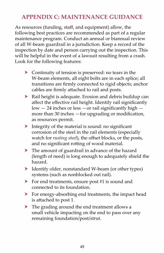
As resources (funding, staff, and equipment) allow, the following best practices are recommended as part of a regular maintenance program. Conduct an annual or biannual review of all W-beam guardrail in a jurisdiction. Keep a record of the inspection by date and person carrying out the inspection. This will be helpful in the event of a lawsuit resulting from a crash. Look for the following features:
Continuity of tension is preserved: no tears in the hW-beam elements, all eight bolts are in each splice; all transitions are firmly connected to rigid objects; anchor cables are firmly attached to rail and posts.Rail height is adequate. Erosion and debris buildup can haffect the effective rail height. Identify rail significantly low — 24 inches or less —or rail significantly high — more than 30 inches —for upgrading or modification, as resources permit.Integrity of the material is sound: no significant hcorrosion of the steel in the rail elements (especially watch for rusting steel), the offset blocks, or the posts, and no significant rotting of wood material.The amount of guardrail in advance of the hazard h(length of need) is long enough to adequately shield the hazard.Identify older, nonstandard W-beam (or other types) hsystems (such as nonblocked out rail).For end treatments, ensure post #1 is sound and hconnected to its foundation.For energy-absorbing end treatments, the impact head his attached to post 1.The grading around the end treatment allows a hsmall vehicle impacting on the end to pass over any remaining foundation/post/strut.

50 51
Ensure adequate, available deflection distance h(generally 3 ft for the standard W-beam system) to vertical rigid objects.Flare (the rate at which the guardrail moves closer to hthe travel way going downstream) is not excessive (not sharper than 1:7 (Vertical:Horizontal)). Check for adequate soil backing (1ft of 1:3 or flatter soil hfor standard 6-ft posts) to provide the stiffness for the posts.Ensure guardrail located on a steeper slope is in hcompliance with the figure below in order to prevent vaulting.
Ensure the offset blocks are not rotated. h
A useful tool for managing this asset is an inventory (with possibly a rating system) of existing W-beam barrier, indicating the type of W-beam (post and offset block material, rail material) and the type of end treatment (model name and materials). The inventory is also useful in setting priorities for improvement projects. The following is an example inventory system being developed by New York State DOT. For additional information on this inventory system, contact NYSDOT’s Transportation Systems Maintenance, 50 Wolf Road, Albany, NY 12232; phone: 518-457-6435.

50 51
New York State Dot Guardrail Inventory System Report.

52 53
APPENDIX D: CLEAR ZONE DESCRIPTION
The concept of clear zone is an approach to minimize the number and severity of crashes involving vehicles running off the road. Simply stated, it is a traversable area that starts at the edge of the traffic lane and extends laterally a sufficient distance to allow a driver to stop or return to the road before encountering a hazard or overturning. The traversable area would be considered safe, if there were no fixed objects, unless they are breakaway, and if the roadside geometry (either the fore slope, back slope, or ditch) was flat enough that a vehicle could safely traverse the area without tipping and rolling over. Roadside safety features include breakaway sign and light posts, and traversable drainage structures. Curbs are not considered a roadside safety feature since they can be easily mounted by errant vehicles; hence, their presence does not alter how clear zone is measured.
A safe traversable slope can be either a recoverable slope or a non-recoverable slope with a clear run-out area at the bottom. A recoverable slope is a slope on which a motorist may, to a greater or lesser extent, retain or regain control of a vehicle and recover or stop. Slopes 1:4 (Vertical:Horizontal) or flatter

52 53
are generally considered recoverable. A non-recoverable, traversable slope is a slope which is considered traversable but on which an errant vehicle will continue to the bottom. Embankment slopes from 1:3 and 1:4 may be considered traversable but non-recoverable if they are smooth and free of fixed objects. A clear run-out area is the flatter area at the toe of a non-recoverable slope available for safe use by an errant vehicle. Slopes steeper than 1:3 are not considered traversable and should not be found in the clear zone.
The objective of roadside safety is to provide and maintain as much clear zone as practical. The design clear zone is the minimum width to be provided on a project and is dependent upon speeds, the roadside geometry, and traffic volumes. Further details on clear zone can be found in the Roadside Design Guide.


Office of SafetyFederal Highway Administration
U.S. Department of Transportation1200 New Jersey Avenue, S.E.
Washington, D.C. 20590
FHWA-SA-08-002