vto3211d-p user’s manual -...
TRANSCRIPT
1
VTO3211D-P User’s Manual
V1.0.0

Table of Contents
Table of Contents ...................................................................................................................... 2
Cybersecurity Statement and Recommendations ..................................................................... 4
Cybersecurity Statement ........................................................................................................... 4
Cybersecurity Recommendations ............................................................................................. 4
1 Product Overview ....................................................................................................... 1
1.1 Product Feature ............................................................................................................. 1
1.2 Networking ..................................................................................................................... 1
2 Structure ..................................................................................................................... 2
2.1 Front Panel ..................................................................................................................... 2
2.2 Rear Panel ...................................................................................................................... 3
3 Install and Debug ........................................................................................................ 5
3.1 Device Wiring ................................................................................................................. 5
3.2 Installation ..................................................................................................................... 5
3.2.1 Screw Specification ............................................................................................. 5
3.2.2 Installation Dimension ........................................................................................ 6
3.2.3 Installation Step .................................................................................................. 7
3.3 Debugging ...................................................................................................................... 9
3.3.1 Before Debugging ............................................................................................... 9
3.3.2 VTO Setup ........................................................................................................... 9
3.3.3 Indoor Manager ................................................................................................ 10
3.3.4 Debugging ......................................................................................................... 13
4 Web Config ................................................................................................................. 1
4.1 WEB Login and Logout ................................................................................................... 1
4.1.1 Login ................................................................................................................... 1
4.1.2 Logout ................................................................................................................. 1
4.2 System Config ................................................................................................................. 2
4.2.1 Local Config ......................................................................................................... 2

4.2.2 LAN Config .......................................................................................................... 8
4.2.3 Indoor Manager .................................................................................................. 9
4.2.4 Network Config ................................................................................................. 12
4.2.5 Video Set ........................................................................................................... 17
4.2.6 User Manager ................................................................................................... 19
4.2.7 IPC ..................................................................................................................... 21
4.2.8 UPnP Setup ....................................................................................................... 22
4.3 Info Search ................................................................................................................... 23
4.3.1 Call History ........................................................................................................ 23
4.3.2 Alarm Record .................................................................................................... 23
4.3.3 Unlock Record ................................................................................................... 24
4.4 Status Statistics ............................................................................................................ 24
4.4.1 VTH Status ........................................................................................................ 24
5 Function Introduction .............................................................................................. 26
5.1 Monitor ........................................................................................................................ 26
5.2 Call ................................................................................................................................ 26
5.3 Unlock Function ........................................................................................................... 26
5.4 Recovery ....................................................................................................................... 26
Appendix 1 Technical Specifications ....................................................................................... 27

Cybersecurity Statement and Recommendations
Cybersecurity Statement
You are responsible for the risks resulting from connecting your product to the
internet, including but not limited to, cyber-attacks, hacking attacks, computer viruses
and malware, etc. Please protect your data and personal information by taking
necessary actions, such as changing the default password and using a strong
combination, changing your password periodically, keeping your firmware up-to-date,
etc. Dahua is not responsible for any dysfunction, information leakage or other
problems caused by failure to take necessary precautions to secure your devices. We
will provide product maintenance services.
To the extent not prohibited by applicable laws, Dahua and its employees, licensees,
and affiliates are not liable for personal injury, or any incidental, special, indirect, or
consequential damages whatsoever, including, without limitation, damages for loss of
profits, corruption or loss of data, failure to transmit or receive any data, business
interruption, or any other commercial damages or losses arising out of or related to
the use or inability to use its products or services, however caused, regardless of the
theory of liability (contract, tort or otherwise), even if it has been advised of the
possibility of such damages. Some jurisdictions do not allow the exclusion or
limitation of liability for personal injury, or of incidental or consequential damages, so
this limitation may not apply to you.
In no event shall liability for all damages (other than as may be required by applicable
laws in cases involving personal injury) exceed the amount paid for products or
services.
Cybersecurity Recommendations
Mandatory actions to be taken towards cybersecurity
1. Change Passwords and Use Strong Passwords:
The number one reason systems get “hacked” is due to having weak or default passwords.
Dahua recommends changing default passwords immediately and choosing a strong
password whenever possible. A strong password should be made up of at least 8
characters and a combination of special characters, numbers, and upper and lower case
letters.
2. Update Firmware
As is standard procedure in the tech-industry, we recommend keeping NVR, DVR, and IP
camera firmware up-to-date to ensure the system is current with the latest security
patches and fixes.
Check the firmware release of your running devices. If the firmware release date is over
18 months old, please contact a Dahua authorized local distributor or Dahua technical
support for available update releases.
“Nice to have” recommendations to improve your network security
1. Change Passwords Regularly
Regularly change the credentials to your devices to help ensure that only authorized users
are able to access the system.
2. Change Default HTTP and TCP Ports:
● Change default HTTP and TCP ports for Dahua systems. These are the two ports used
to communicate and to view video feeds remotely.
● These ports can be changed to any set of numbers between 1025-65535. Avoiding the
default ports reduces the risk of outsiders being able to guess which ports you are using.
3. Enable HTTPS/SSL:
Set up an SSL Certificate to enable HTTPS. This will encrypt all communication between
your devices and recorder.
4. Enable IP Filter:
Enabling your IP filter will prevent everyone, except those with specified IP addresses,
from accessing the system.
5. Change ONVIF Password:
On older IP Camera firmware, the ONVIF password does not change when you change
the system’s credentials. You will need to either update the camera’s firmware to the
latest revision or manually change the ONVIF password.
6. Forward Only Ports You Need:
● Only forward the HTTP and TCP ports that you need to use. Do not forward a huge
range of numbers to the device. Do not DMZ the device's IP address.
● You do not need to forward any ports for individual cameras if they are all connected to
a recorder on site; just the NVR is needed.
7. Disable Auto-Login on SmartPSS:
Those using SmartPSS to view their system and on a computer that is used by multiple
people should disable auto-login. This adds a layer of security to prevent users without the
appropriate credentials from accessing the system.
8. Use a Different Username and Password for SmartPSS:
In the event that your social media, bank, email, etc. account is compromised, you would
not want someone collecting those passwords and trying them out on your video
surveillance system. Using a different username and password for your security system
will make it more difficult for someone to guess their way into your system.
9. Limit Features of Guest Accounts:
If your system is set up for multiple users, ensure that each user only has rights to
features and functions they need to use to perform their job.
10. UPnP:
● UPnP will automatically try to forward ports in your router or modem. Normally this
would be a good thing. However, if your system automatically forwards the ports and you
leave the credentials defaulted, you may end up with unwanted visitors.
● If you manually forwarded the HTTP and TCP ports in your router/modem, this feature
should be turned off regardless. Disabling UPnP is recommended when the function is not
used in real applications.
11. SNMP:
Disable SNMP if you are not using it. If you are using SNMP, you should do so only
temporarily, for tracing and testing purposes only.
12. Multicast:
Multicast is used to share video streams between two recorders. Currently there are no
known issues involving Multicast, but if you are not using this feature, deactivation can
enhance your network security.
13. Check the Log:
If you suspect that someone has gained unauthorized access to your system, you can
check the system log. The system log will show you which IP addresses were used to
login to your system and what was accessed.
14. Physically Lock Down the Device:
Ideally, you want to prevent any unauthorized physical access to your system. The best
way to achieve this is to install the recorder in a lockbox, locking server rack, or in a room
that is behind a lock and key.
15. Connect IP Cameras to the PoE Ports on the Back of an NVR:
Cameras connected to the PoE ports on the back of an NVR are isolated from the outside
world and cannot be accessed directly.
16. Isolate NVR and IP Camera Network

The network your NVR and IP camera resides on should not be the same network as your
public computer network. This will prevent any visitors or unwanted guests from getting
access to the same network the security system needs in order to function properly.
For latest information about Dahua the cybersecurity statement and recommendations,
please visit www.dahuasecurity.com.

1
1 Product Overview
1.1 Product Feature
Metal VTO has simple operation, easy installation with the following functions:
Mobile phone live preview.
Call and intercom with VTH.
Unlock door by card.
Vandal-proof alarm.
1.2 Networking
Figure 1-1
2 Structure
2.1 Front Panel
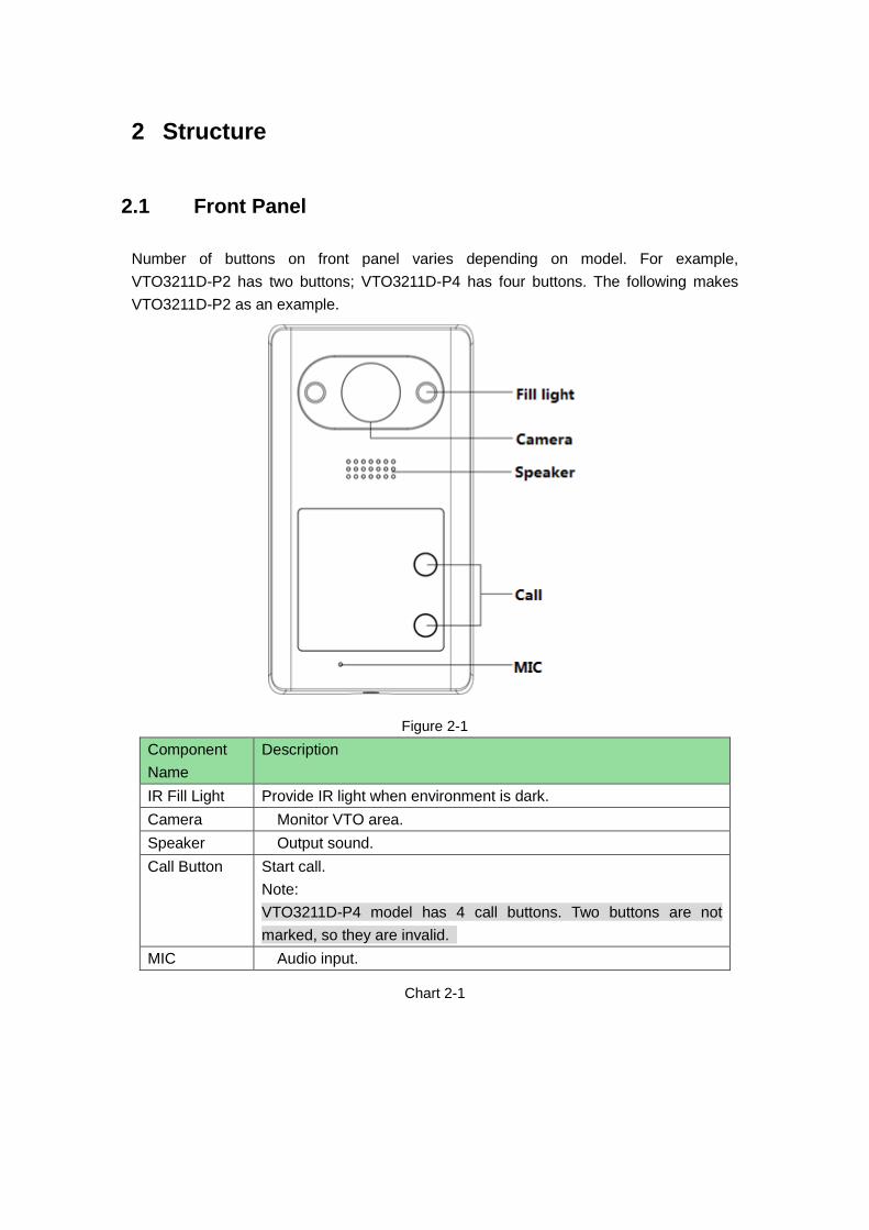
Number of buttons on front panel varies depending on model. For example,
VTO3211D-P2 has two buttons; VTO3211D-P4 has four buttons. The following makes
VTO3211D-P2 as an example.
Figure 2-1
Component
Name
Description
IR Fill Light Provide IR light when environment is dark.
Camera Monitor VTO area.
Speaker Output sound.
Call Button Start call.
Note:
VTO3211D-P4 model has 4 call buttons. Two buttons are not
marked, so they are invalid.
MIC Audio input.
Chart 2-1

2.2 Rear Panel
Figure 1- 1
Figure 2-2
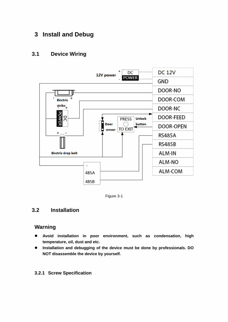
Label Note
DC12V DC12V power port
GND Ground
DOOR-NO Door lock NO port
DOOR-COM Lock public port
DOOR-NC Lock NC port

Label Note
DOOR-FEED Lock door sensor feedback
DOOR-OPEN Door lock unlock button
RS485A RS485 communication
RS485B
ALM-IN Alarm input
ALM-NO Alarm output
ALM-COM
Chart 2-2
3 Install and Debug
3.1 Device Wiring
Figure 3-1
3.2 Installation
Warning
Avoid installation in poor environment, such as condensation, high
temperature, oil, dust and etc.
Installation and debugging of the device must be done by professionals. DO
NOT disassemble the device by yourself.
3.2.1 Screw Specification

Component Name Figure Quantity
White expansion bolt
Φ6×30mm 4
ST3×20 self-tapping
screw 4
M3×6 mechanic screw
1
Chart 3-1
3.2.2 Installation Dimension
Figure 3-2
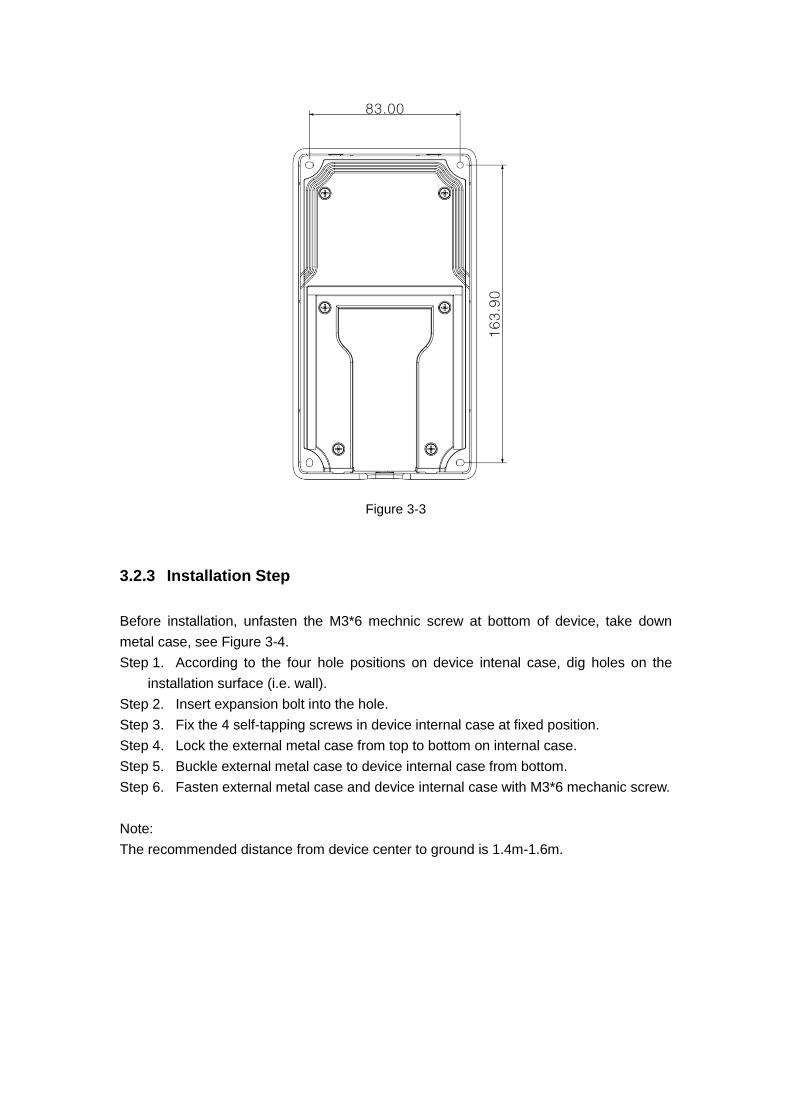
Figure 3-3
3.2.3 Installation Step
Before installation, unfasten the M3*6 mechnic screw at bottom of device, take down
metal case, see Figure 3-4.
Step 1. According to the four hole positions on device intenal case, dig holes on the
installation surface (i.e. wall).
Step 2. Insert expansion bolt into the hole.
Step 3. Fix the 4 self-tapping screws in device internal case at fixed position.
Step 4. Lock the external metal case from top to bottom on internal case.
Step 5. Buckle external metal case to device internal case from bottom.
Step 6. Fasten external metal case and device internal case with M3*6 mechanic screw.
Note:
The recommended distance from device center to ground is 1.4m-1.6m.
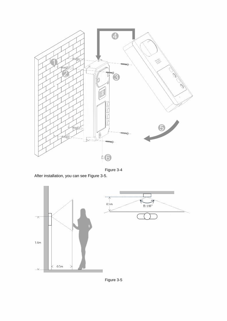
Figure 3-4
After installation, you can see Figure 3-5.
Figure 3-5
3.3 Debugging
3.3.1 Before Debugging
The following makes VTH5221D and 7 inch VTH pairing for debugginng.
Before debugging, the staff shall be familiar with device’s installation, wiring and
usage.
Before debugging, check wiring for short or open circuit.
Ensure VTH can work normally.
3.3.2 VTO Setup
VTO default IP address of 192.168.1.110. Before you use VTO, you must change IP
address to a IP address in the same segment with VTH.
Step 1. Plug VTO to power.
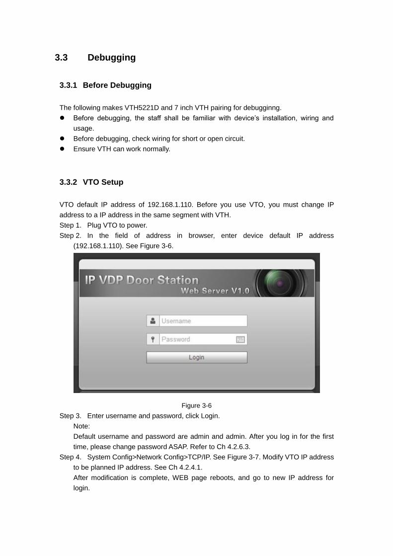
Step 2. In the field of address in browser, enter device default IP address
(192.168.1.110). See Figure 3-6.
Figure 3-6
Step 3. Enter username and password, click Login.
Note:
Default username and password are admin and admin. After you log in for the first
time, please change password ASAP. Refer to Ch 4.2.6.3.
Step 4. System Config>Network Config>TCP/IP. See Figure 3-7. Modify VTO IP address
to be planned IP address. See Ch 4.2.4.1.
After modification is complete, WEB page reboots, and go to new IP address for
login.

Figure 3-7
Step 5. Select System Config>Indoor Manager>Indoor Manager. See Figure 3-8. Click
Add to add VTH info.
Figure 3-8
Step 6. Click System Config>Local Config>Facase Layout, click white area on the left,
and select VTH room no., see Figure 3-9.
Figure 3-9
3.3.3 Indoor Manager
Step 1. In VTH homepage, long press Setup for 6 seconds.
Step 2. Enter password in VTH project setup interface.
Step 3. Click Network Setup to connect VTH network. See
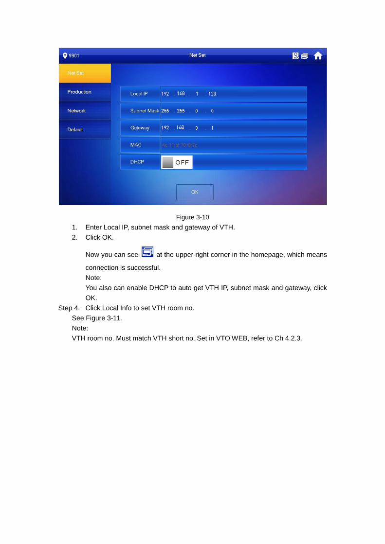
Figure 3-10
1. Enter Local IP, subnet mask and gateway of VTH.
2. Click OK.
Now you can see at the upper right corner in the homepage, which means
connection is successful.
Note:
You also can enable DHCP to auto get VTH IP, subnet mask and gateway, click
OK.
Step 4. Click Local Info to set VTH room no.
See Figure 3-11.
Note:
VTH room no. Must match VTH short no. Set in VTO WEB, refer to Ch 4.2.3.
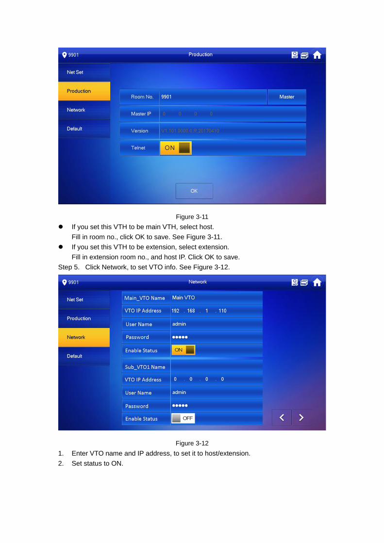
Figure 3-11
If you set this VTH to be main VTH, select host.
Fill in room no., click OK to save. See Figure 3-11.
If you set this VTH to be extension, select extension.
Fill in extension room no., and host IP. Click OK to save.
Step 5. Click Network, to set VTO info. See Figure 3-12.
Figure 3-12
1. Enter VTO name and IP address, to set it to host/extension.
2. Set status to ON.
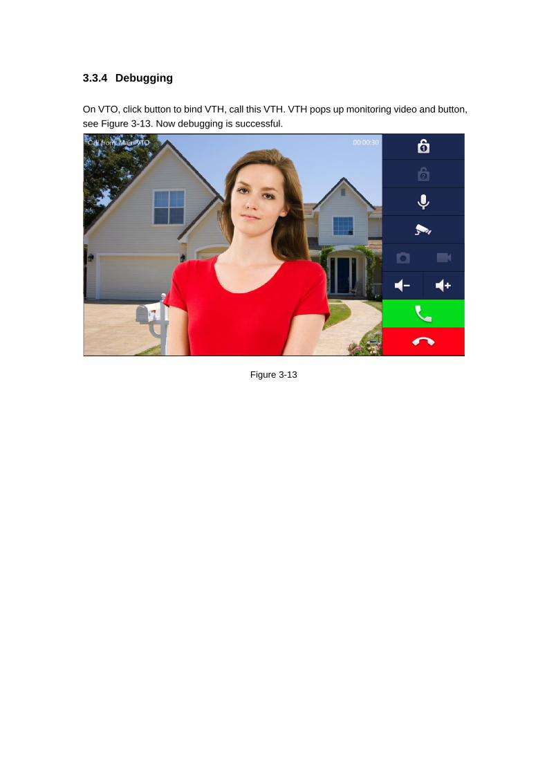
3.3.4 Debugging
On VTO, click button to bind VTH, call this VTH. VTH pops up monitoring video and button,
see Figure 3-13. Now debugging is successful.
Figure 3-13
1
4 Web Config
This chapter introduces VTO WEB interface and its parameters, and how to configure
them.
4.1 WEB Login and Logout
4.1.1 Login
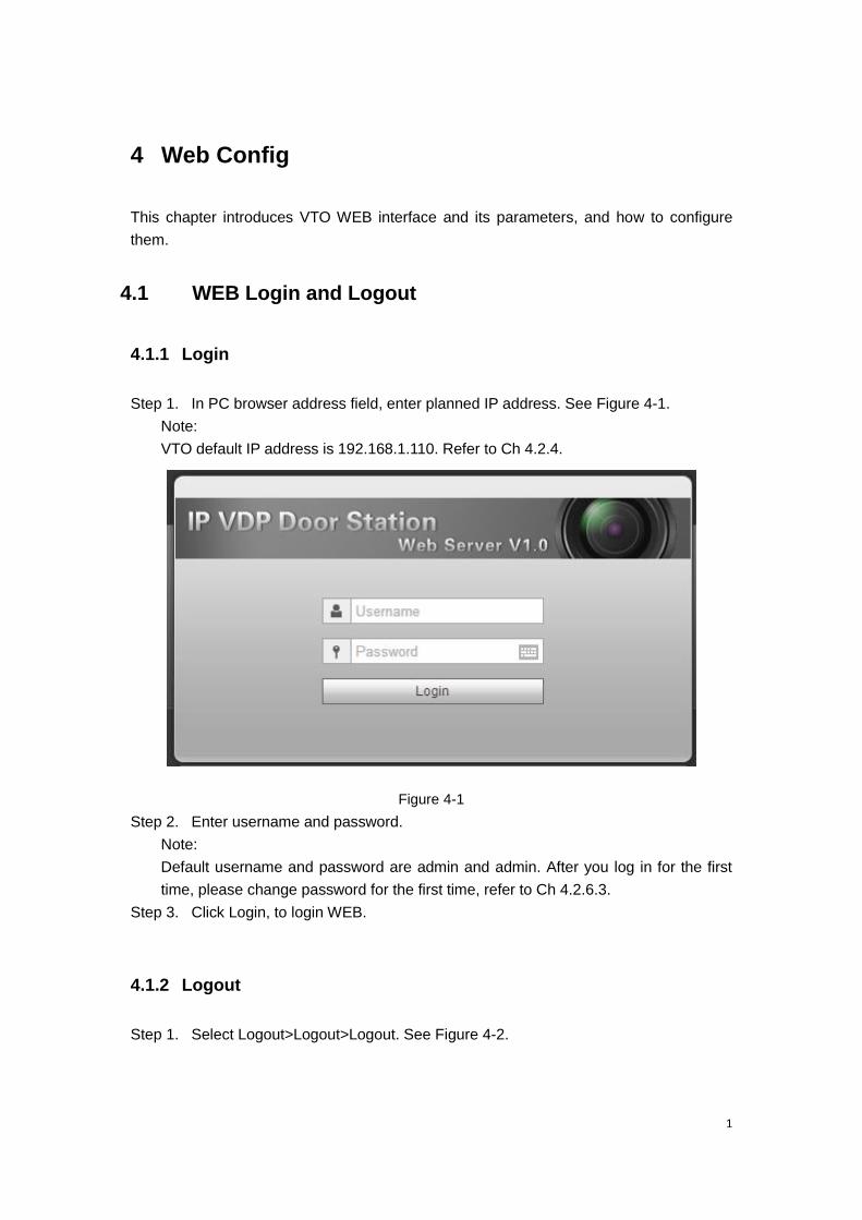
Step 1. In PC browser address field, enter planned IP address. See Figure 4-1.
Note:
VTO default IP address is 192.168.1.110. Refer to Ch 4.2.4.
Figure 4-1
Step 2. Enter username and password.
Note:
Default username and password are admin and admin. After you log in for the first
time, please change password for the first time, refer to Ch 4.2.6.3.
Step 3. Click Login, to login WEB.
4.1.2 Logout
Step 1. Select Logout>Logout>Logout. See Figure 4-2.

Figure 4-2
Step 2. Click Logout.
You also can reboot system in Logout>Reboot Device>Reboot Device.
4.2 System Config
4.2.1 Local Config
4.2.1.1 Local Config
System Config>Local Config>Local Config interface, you can set light sensitivity,
brightness and etc.
Figure 4- 1
Parameter Note
Sensor When environment is dark, it auto enables fill light.
Storage Point Storage point of record and image. You can select FTP or SD card.
FTP setup is in Ch 错误!未找到引用源。.
Device Type Select current device type, as villa VTO.
Reboot Date Set device reboot date, default is every 2AM on Tuesday.
Version Info Show device software version no.
Dial Rule VTH room no. has continuous and discontinuous.
Default Click Default, restore all parameters in this page to default.
Refresh Click Refresh, to refresh current interface info.
OK Click OK to save setup.
Chart 4-1
Parameter Note
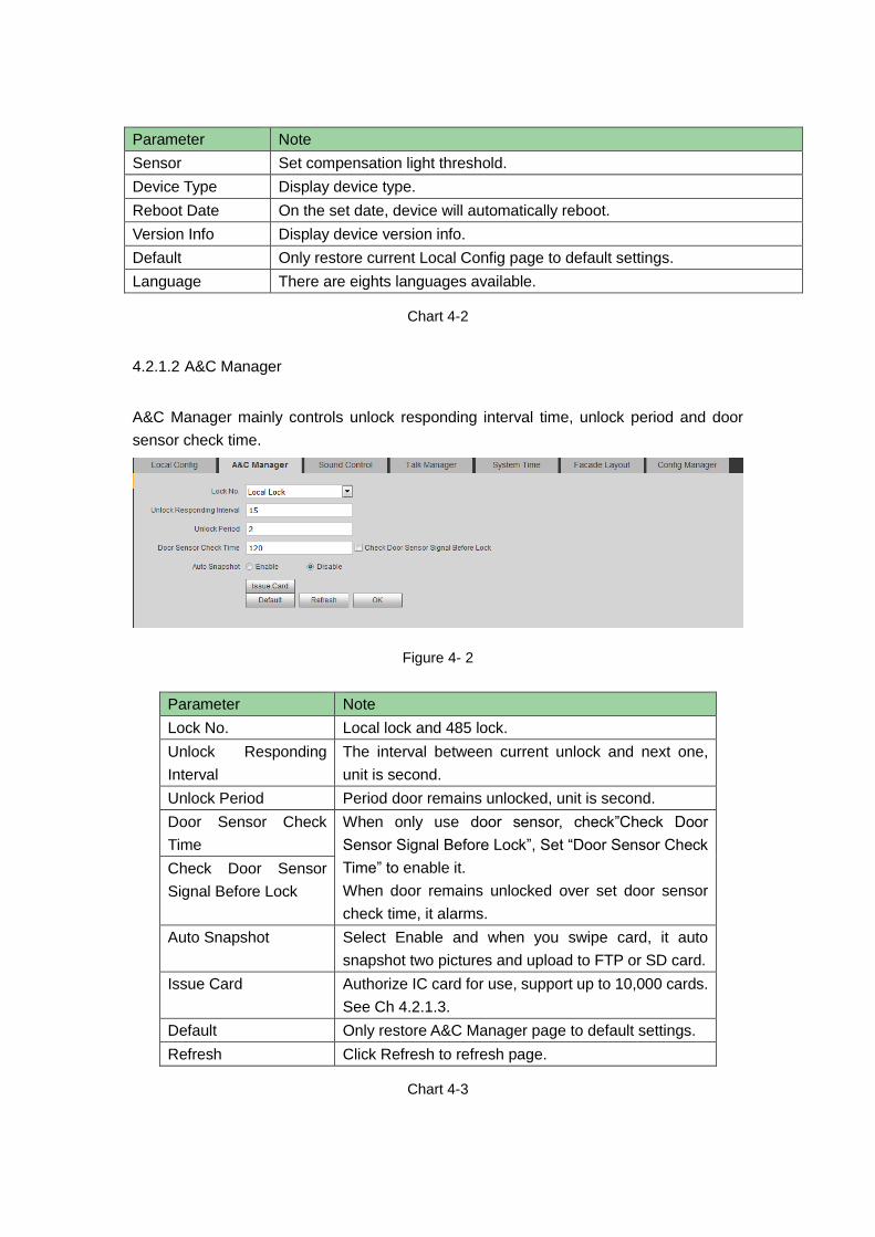
Sensor Set compensation light threshold.
Device Type Display device type.
Reboot Date On the set date, device will automatically reboot.
Version Info Display device version info.
Default Only restore current Local Config page to default settings.
Language There are eights languages available.
Chart 4-2
4.2.1.2 A&C Manager
A&C Manager mainly controls unlock responding interval time, unlock period and door
sensor check time.
Figure 4- 2
Parameter Note
Lock No. Local lock and 485 lock.
Unlock Responding
Interval
The interval between current unlock and next one,
unit is second.
Unlock Period Period door remains unlocked, unit is second.
Door Sensor Check
Time
When only use door sensor, check”Check Door
Sensor Signal Before Lock”, Set “Door Sensor Check
Time” to enable it.
When door remains unlocked over set door sensor
check time, it alarms.
Check Door Sensor
Signal Before Lock
Auto Snapshot Select Enable and when you swipe card, it auto
snapshot two pictures and upload to FTP or SD card.
Issue Card Authorize IC card for use, support up to 10,000 cards.
See Ch 4.2.1.3.
Default Only restore A&C Manager page to default settings.
Refresh Click Refresh to refresh page.
Chart 4-3

4.2.1.3 Card Manager
Note:
Before you issue card, please all VTH, referring to Ch 4.2.3.1.
Step 1. System Config>Local Config>A&C Manager.
Step 2. Click Issue Card and place IC card close to card area. See Figure 4-3.
Figure 4-3
Step 3. Enter corresponding username and room no. of IC card, click OK.
Note:
Room no. in card info shall match room no. on VTH.
Step 4. Click OK. You can go to System Config>Indoor Manager>Digital Indoor Station
Manager to view by clicking .
4.2.1.4 Sound Control
System Config>Local Config>Sound Control, you can enable or disable ring tone, unlock,
alarm and speech tone.
Figure 4-4
4.2.1.5 Talk Manager
The device supports talk management and you can enable and disable upload of talk call
record, message and auto snapshot.

Figure 4-5
Parameter Note
Auto Snapshot Select Enable, and during call, it auto snapshot three pictures and
upload to FTP or SD card.
Leave Message
Upload
Select Enable, VTO calls VTH, and when no one answers, you can
follow instructions to leave message.
Message file is stored in SD card, and you can read it on VTH.
Note:
If you set 0 second here, then no message is allowed. All other
number set will allow system to ask user whether to leave a
message.
Upload Talk
Record
Select Enable, upload talk record. You can view in Info
Search>Unlock Record>Call Record.
Chart 4-4
4.2.1.6 System Time
Here you can set date format, time format(24-hour and 12-hour), and input system date
and time. You can also click on Sync PC to synchronize system time with PC time. You
also can set DST start time.
Figure 4- 3

Parameter Note
Date Format Set date display mode.
Time Format Set time display mode, as 12 hour and 24 hour.
System Time Set system display time.
Sync PC Click Sync PC to sync time with local PC.
DST Enable
Check DST Enable, to enable DST.
Set start time and end time of DST.
DST Type
Start Time
End Time
NTP Enable
Check NTP Enable to enable NTP server.
You can set input of IP, time zone, port no. and interval of server where NTP
server is installed. Set sync time.
NTP Server
Zone
Port No.
Update Period
Default Click Default to restore all parameters here to default.
Refresh Click Refresh to refresh current page.
Chart 4-5
4.2.1.7 Facade Layout
System Config>Local Config>, you can set button and bind VTH.
Figure 4-6
Click white area on the left of each button, like . Select VTH room no. bound to
this button (VTH short no.), click OK.
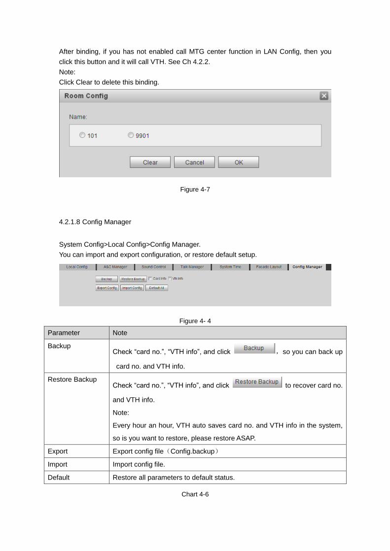
After binding, if you has not enabled call MTG center function in LAN Config, then you
click this button and it will call VTH. See Ch 4.2.2.
Note:
Click Clear to delete this binding.
Figure 4-7
4.2.1.8 Config Manager
System Config>Local Config>Config Manager.
You can import and export configuration, or restore default setup.
Figure 4- 4
Parameter Note
Backup Check “card no.”, “VTH info”, and click ,so you can back up
card no. and VTH info.
Restore Backup Check “card no.”, “VTH info”, and click to recover card no.
and VTH info.
Note:
Every hour an hour, VTH auto saves card no. and VTH info in the system,
so is you want to restore, please restore ASAP.
Export Export config file(Config.backup)
Import Import config file.
Default Restore all parameters to default status.
Chart 4-6
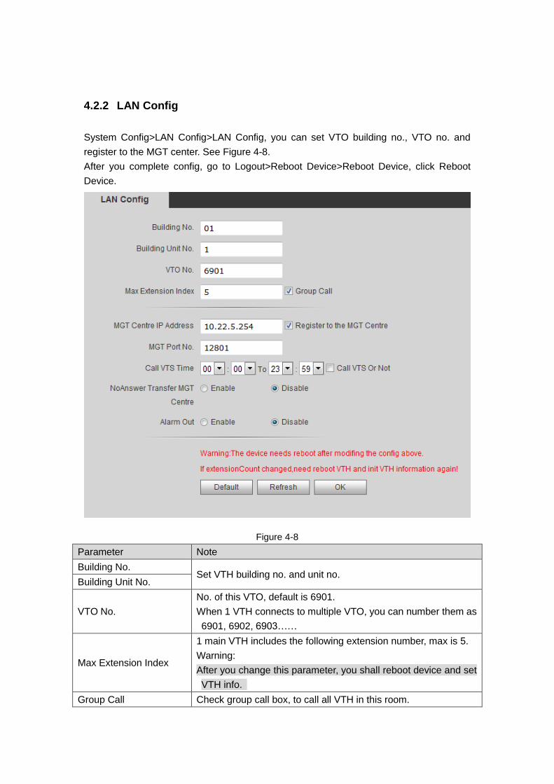
4.2.2 LAN Config
System Config>LAN Config>LAN Config, you can set VTO building no., VTO no. and
register to the MGT center. See Figure 4-8.
After you complete config, go to Logout>Reboot Device>Reboot Device, click Reboot
Device.
Figure 4-8
Parameter Note
Building No. Set VTH building no. and unit no.
Building Unit No.
VTO No.
No. of this VTO, default is 6901.
When 1 VTH connects to multiple VTO, you can number them as
6901, 6902, 6903……
Max Extension Index
1 main VTH includes the following extension number, max is 5.
Warning:
After you change this parameter, you shall reboot device and set
VTH info.
Group Call Check group call box, to call all VTH in this room.
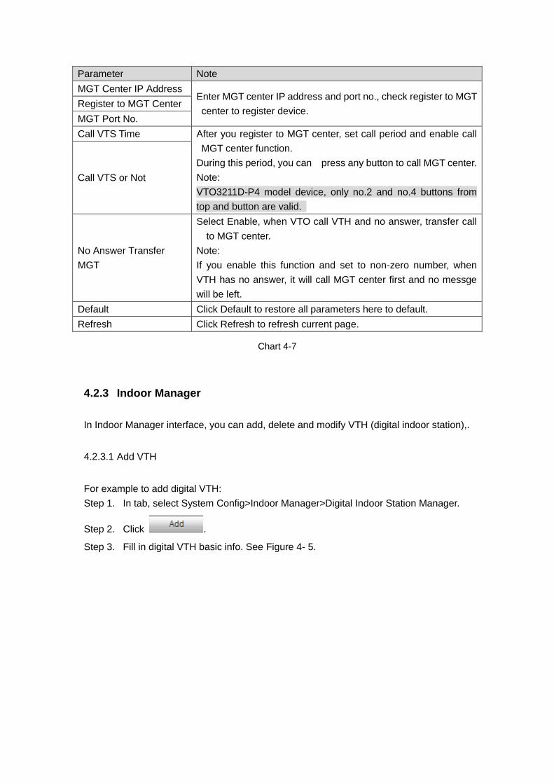
Parameter Note
MGT Center IP Address Enter MGT center IP address and port no., check register to MGT
center to register device. Register to MGT Center
MGT Port No.
Call VTS Time After you register to MGT center, set call period and enable call
MGT center function.
During this period, you can press any button to call MGT center.
Note:
VTO3211D-P4 model device, only no.2 and no.4 buttons from
top and button are valid.
Call VTS or Not
No Answer Transfer
MGT
Select Enable, when VTO call VTH and no answer, transfer call
to MGT center.
Note:
If you enable this function and set to non-zero number, when
VTH has no answer, it will call MGT center first and no messge
will be left.
Default Click Default to restore all parameters here to default.
Refresh Click Refresh to refresh current page.
Chart 4-7
4.2.3 Indoor Manager
In Indoor Manager interface, you can add, delete and modify VTH (digital indoor station),.
4.2.3.1 Add VTH
For example to add digital VTH:
Step 1. In tab, select System Config>Indoor Manager>Digital Indoor Station Manager.
Step 2. Click .
Step 3. Fill in digital VTH basic info. See Figure 4- 5.
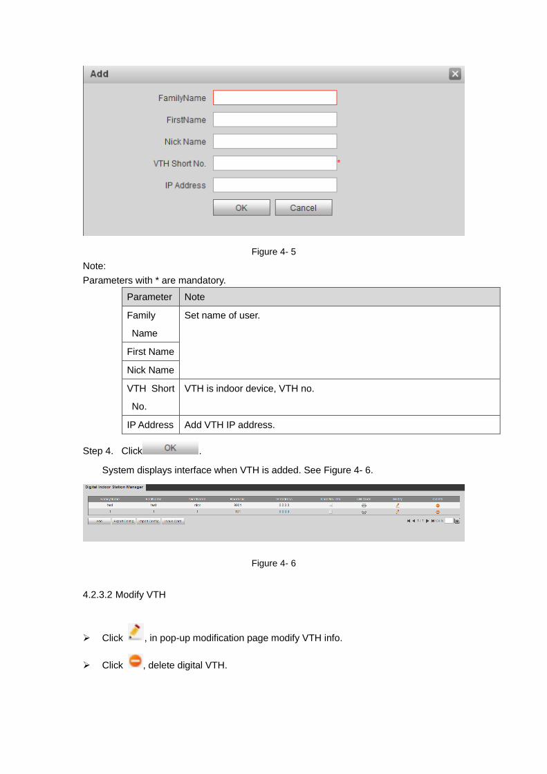
Figure 4- 5
Note:
Parameters with * are mandatory.
Parameter Note
Family
Name
Set name of user.
First Name
Nick Name
VTH Short
No.
VTH is indoor device, VTH no.
IP Address Add VTH IP address.
Step 4. Click .
System displays interface when VTH is added. See Figure 4- 6.
Figure 4- 6
4.2.3.2 Modify VTH
Click , in pop-up modification page modify VTH info.
Click , delete digital VTH.
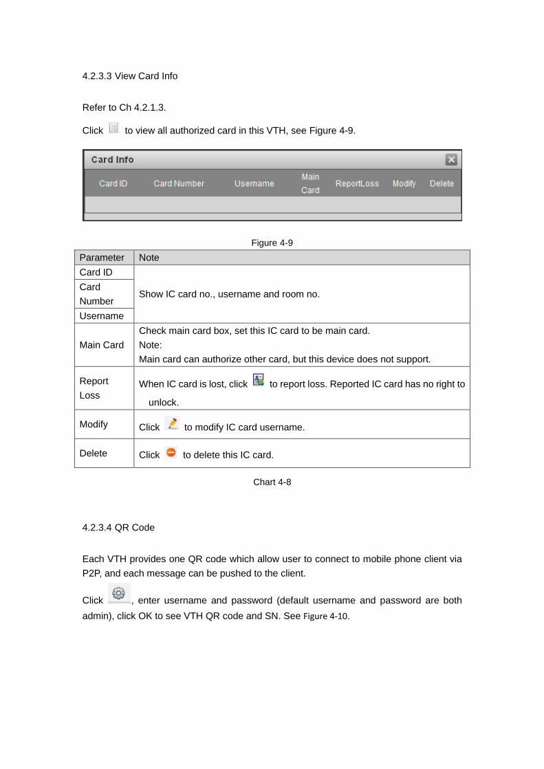
4.2.3.3 View Card Info
Refer to Ch 4.2.1.3.
Click to view all authorized card in this VTH, see Figure 4-9.
Figure 4-9
Parameter Note
Card ID
Show IC card no., username and room no. Card
Number
Username
Main Card
Check main card box, set this IC card to be main card.
Note:
Main card can authorize other card, but this device does not support.
Report
Loss When IC card is lost, click to report loss. Reported IC card has no right to
unlock.
Modify Click to modify IC card username.
Delete Click to delete this IC card.
Chart 4-8
4.2.3.4 QR Code
Each VTH provides one QR code which allow user to connect to mobile phone client via
P2P, and each message can be pushed to the client.
Click , enter username and password (default username and password are both
admin), click OK to see VTH QR code and SN. See Figure 4-10.

Figure 4-10
Warning:
After your mobile phone scan the QR code, and when you add device, you must has
enabled P2P function of VTO, see Ch 4.2.4.5.
4.2.3.5 Import/Export Config
You can import config or export config of VTH or card info.
Click Export Config, to export existing VTH info or card info.
Click Import Config, to import existing VTH info or card info.
4.2.4 Network Config
4.2.4.1 TCP/IP
You can set local IP network parameter.
Select System Config>Network>TCP/IP. Set local IP address, subnet mask and default
gateway.
See Figure 4- 7.
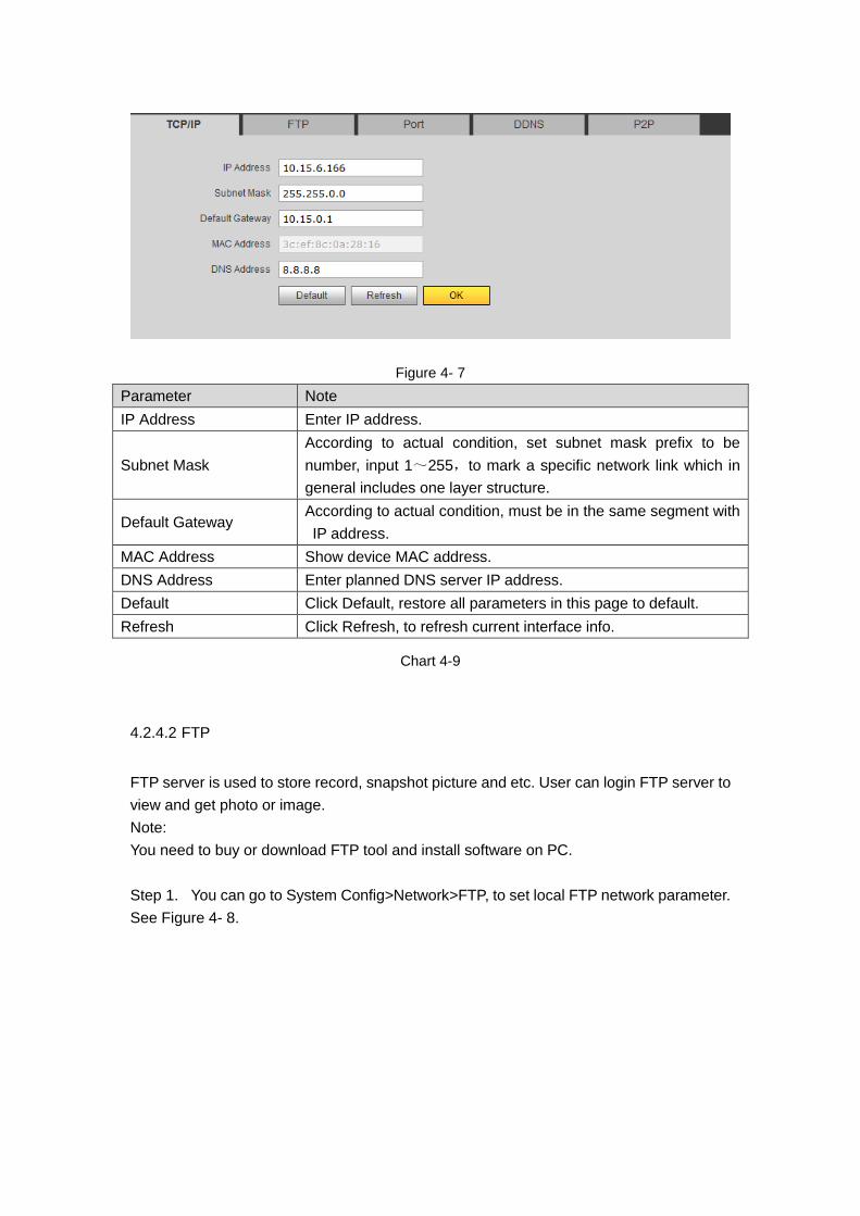
Figure 4- 7
Parameter Note
IP Address Enter IP address.
Subnet Mask
According to actual condition, set subnet mask prefix to be
number, input 1~255,to mark a specific network link which in
general includes one layer structure.
Default Gateway According to actual condition, must be in the same segment with
IP address.
MAC Address Show device MAC address.
DNS Address Enter planned DNS server IP address.
Default Click Default, restore all parameters in this page to default.
Refresh Click Refresh, to refresh current interface info.
Chart 4-9
4.2.4.2 FTP
FTP server is used to store record, snapshot picture and etc. User can login FTP server to
view and get photo or image.
Note:
You need to buy or download FTP tool and install software on PC.
Step 1. You can go to System Config>Network>FTP, to set local FTP network parameter.
See Figure 4- 8.
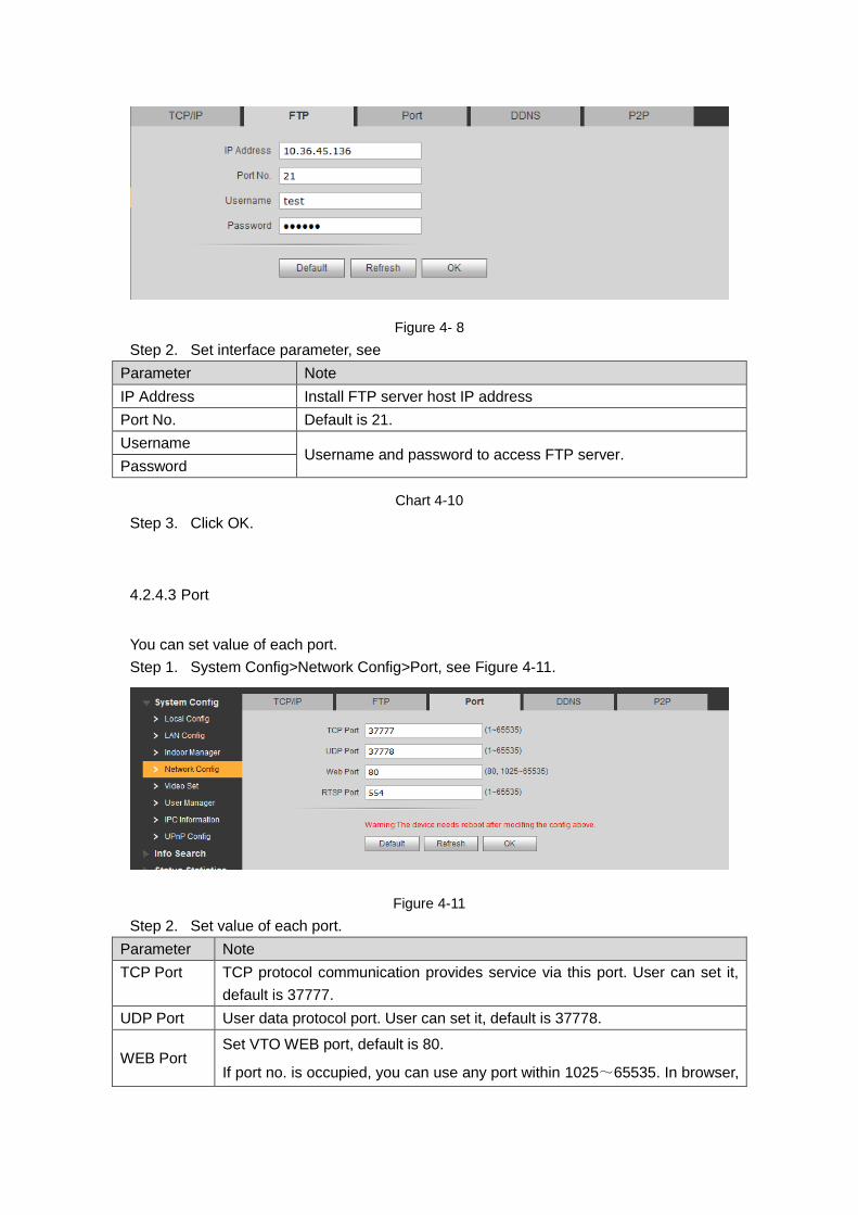
Figure 4- 8
Step 2. Set interface parameter, see
Parameter Note
IP Address Install FTP server host IP address
Port No. Default is 21.
Username Username and password to access FTP server.
Password
Chart 4-10
Step 3. Click OK.
4.2.4.3 Port
You can set value of each port.
Step 1. System Config>Network Config>Port, see Figure 4-11.
Figure 4-11
Step 2. Set value of each port.
Parameter Note
TCP Port TCP protocol communication provides service via this port. User can set it,
default is 37777.
UDP Port User data protocol port. User can set it, default is 37778.
WEB Port Set VTO WEB port, default is 80.
If port no. is occupied, you can use any port within 1025~65535. In browser,

Parameter Note
enter to access VTO WEB.
RTSP Port
RTSP port number defaults to 554, if the default can not fill out. Users
can use the following format when using the Apple browser QuickTime or
VLC playback real-time monitoring. BlackBerry also supports this
feature.
real-time monitoring stream stream URL format, request real-time
monitoring stream RTSP streaming media services, the URL should be
specified in the request channel number, stream type, if the need for
authentication information, but also need to provide user name and
password.
When users use the BlackBerry to access, the code stream coding mode
is set to H.264B, the resolution is set to CIF, and the audio is turned off.
The URL format is as follows:
Rtsp: // username: password @ ip: port / cam / realmonitor? Channel = 1 &
subtype = 0
Username: username, such as admin.
password: password, such as admin.
ip: device IP, such as 10.7.8.122.
Port: port number, the default is 554, if the default can not fill out.
channel: channel number, starting at 1. Such as channel 2, then channel
= 2
subtype: stream type, the main stream is 0 (ie subtype = 0), auxiliary
stream is 1 (ie subtype = 1).
For example, request a channel 2 of a device's stream, as follows:
Rtsp: // admin: [email protected]: 554 / cam / realmonitor? Channel = 2 &
subtype = 1
If you do not need authentication, the user name and password do not need
to specify, use the following format:
Rtsp: // ip: port / cam / realmonitor? Channel = 1 & subtype = 0
Chart 4-11
Step 3. Click OK.
4.2.4.4 DDNS Config
DDNS(Dynamic Domain Name Server), is dynamic upgrade of domain name and IP
address of DNS server when device IP address is changing frequently. This can
guarantee user access to device via domain name.
Warning:
Before config, please make sure the device support DNS type, and login
corresponding DDNS username, password and etc.
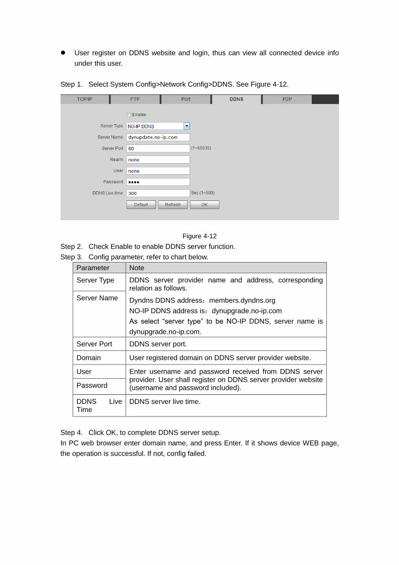
User register on DDNS website and login, thus can view all connected device info
under this user.
Step 1. Select System Config>Network Config>DDNS. See Figure 4-12.
Figure 4-12
Step 2. Check Enable to enable DDNS server function.
Step 3. Config parameter, refer to chart below.
Parameter Note
Server Type DDNS server provider name and address, corresponding relation as follows.
Dyndns DDNS address:members.dyndns.org
NO-IP DDNS address is:dynupgrade.no-ip.com
As select “server type” to be NO-IP DDNS, server name is
dynupgrade.no-ip.com.
Server Name
Server Port DDNS server port.
Domain User registered domain on DDNS server provider website.
User Enter username and password received from DDNS server provider. User shall register on DDNS server provider website (username and password included). Password
DDNS Live Time
DDNS server live time.
Step 4. Click OK, to complete DDNS server setup.
In PC web browser enter domain name, and press Enter. If it shows device WEB page,
the operation is successful. If not, config failed.
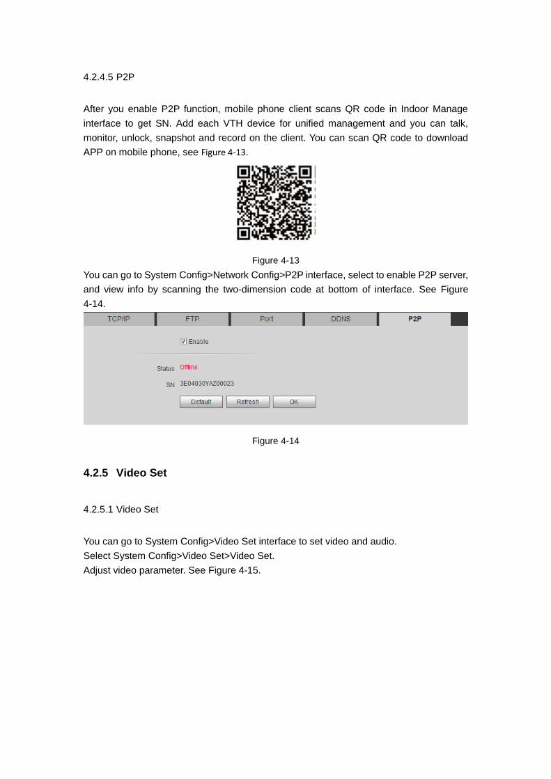
4.2.4.5 P2P
After you enable P2P function, mobile phone client scans QR code in Indoor Manage
interface to get SN. Add each VTH device for unified management and you can talk,
monitor, unlock, snapshot and record on the client. You can scan QR code to download
APP on mobile phone, see Figure 4-13.
Figure 4-13
You can go to System Config>Network Config>P2P interface, select to enable P2P server,
and view info by scanning the two-dimension code at bottom of interface. See Figure
4-14.
Figure 4-14
4.2.5 Video Set
4.2.5.1 Video Set
You can go to System Config>Video Set interface to set video and audio.
Select System Config>Video Set>Video Set.
Adjust video parameter. See Figure 4-15.

Figure 4-15
Note:
If you have not installed plug-in, please install plug-in following instructions.
Parameter Note
Main Format
Video Format Adjust video image resolution, as 720P, WVGA and D1.
Frame Rate Adjust video image transmission speed, as 3fps, 25fps
and 30fps.
Bit Rate According to actual device input, select bit rate, as
256Kbps,512Kbps,1Mbps,2Mbps and 3Mbps.
Extra Format
Video Format Adjust video image resolution, as WVGA, D1 and QVGA.
Frame Rate Adjust video image transmission speed, as 3fps, 25fps
and 30fps.
Bit Rate According to actual device input, select bit rate, as
256Kbps,512Kbps,1Mbps,2Mbps and 3Mbps.
Brightness Adjust video brightness, recommended value is 40~60,
range is 0~100.
Contrast Adjust video image contrast, recommended value is
40~60, range is 0~100.
Hue Adjust image hue and saturation.
Saturation Adjust color saturation, recommended value is 40~60,
range is 0~100.
Gamma Optimize output image in nonlinear method, as an aux to
brightness and contrast.
Scene Mode Select mode: automatic, sunny, night and etc.

Parameter Note
Day/Night Mode Include:color, auto and B/W.
Back Light Mode Include:OFF, back light, WDR, HLC.
Mirror Make image displayed in mirror.
Flip Display image in flip.
Default Reset video effect and volume to default.
Unlock Unlock via web.
Chart 4-12
4.2.5.2 Audio Set
Go to System Config>Video Set>Audio Set interface, you can set MIC volume and beep
volume. See Figure 4-16.
Figure 4-16
4.2.6 User Manager
Only when you login as admin, you can add, modify, delete and view user info in User
Manage interface.
4.2.6.1 Add User
Step 1. Select System Config>User Manager>User Manager, system enters User
Manager interface.
Step 2. Click Add.
Step 3. Configure user info to add. See Figure 4-17.
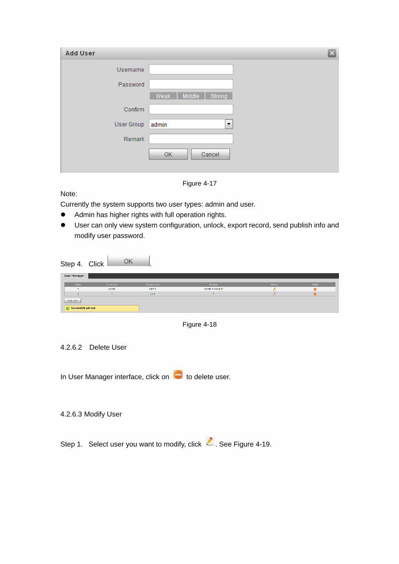
Figure 4-17
Note:
Currently the system supports two user types: admin and user.
Admin has higher rights with full operation rights.
User can only view system configuration, unlock, export record, send publish info and
modify user password.
Step 4. Click .
Figure 4-18
4.2.6.2 Delete User
In User Manager interface, click on to delete user.
4.2.6.3 Modify User
Step 1. Select user you want to modify, click . See Figure 4-19.

Figure 4-19
Step 2. Check Change Password, to see old password, new password and confirm.
Step 3. Set parameter.
Step 4. Click OK.
4.2.7 IPC
You can add up to 64 IPCs, first 32 channels can be modified. Added cameras will be auto
synced with VTH.
To add IPC:
Step 1. You can go to System Config>IPC info interface, view and modify all IPC info.
Step 1. Select System Config>IPC information>IPC information.
Step 2. Click .
Modify IPC info. See Figure 4- 9.
Figure 4- 9
Step 3.
Parameter Note
IPC Name IPC name.

Parameter Note
IP
Address
IPC IP.
Username Username and password to log in IPC WEB page.
Password
Chart 4-13
Step 4. Click .
4.2.8 UPnP Setup
Warning:
Login router, set router WAN port IP address connection to WAN.
Router enables UPnP function.
Connect device to router LAN port, to private network.
Via UPnP protocol create mapping relationship between private network and outer
network. Outer network user can visit device in LAN via outer IP address.
Step 1. Select System Config>UPnP Setup>UPnP.
Step 2. Check “UPnP Enable” to enable UPnP function.
Step 3. Click Add. See Figure 4-20.
Figure 4-20
Step 4. Enable UPnP function, select enable, see chart below.
Parameter Note
Server
Name
Server name.
Protocol
Type
Select protocol type, TCP or UDP.
Inport Port to mapping.
Outport Port mapped on router.
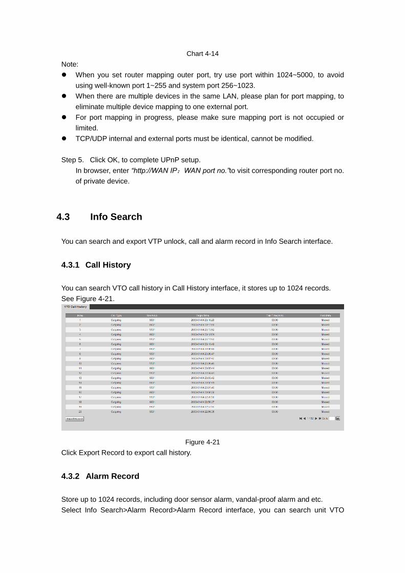
Chart 4-14
Note:
When you set router mapping outer port, try use port within 1024~5000, to avoid
using well-known port 1~255 and system port 256~1023.
When there are multiple devices in the same LAN, please plan for port mapping, to
eliminate multiple device mapping to one external port.
For port mapping in progress, please make sure mapping port is not occupied or
limited.
TCP/UDP internal and external ports must be identical, cannot be modified.
Step 5. Click OK, to complete UPnP setup.
In browser, enter “http://WAN IP:WAN port no.”to visit corresponding router port no.
of private device.
4.3 Info Search
You can search and export VTP unlock, call and alarm record in Info Search interface.
4.3.1 Call History
You can search VTO call history in Call History interface, it stores up to 1024 records.
See Figure 4-21.
Figure 4-21
Click Export Record to export call history.
4.3.2 Alarm Record
Store up to 1024 records, including door sensor alarm, vandal-proof alarm and etc.
Select Info Search>Alarm Record>Alarm Record interface, you can search unit VTO
alarm, including room no., alarm status and etc., see Figure 4-22.
Figure 4-22
Click Export Record to export VTO alarm record.
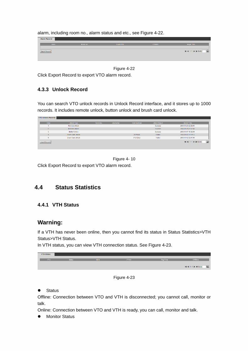
4.3.3 Unlock Record
You can search VTO unlock records in Unlock Record interface, and it stores up to 1000
records. It includes remote unlock, button unlock and brush card unlock.
Figure 4- 10
Click Export Record to export VTO alarm record.
4.4 Status Statistics
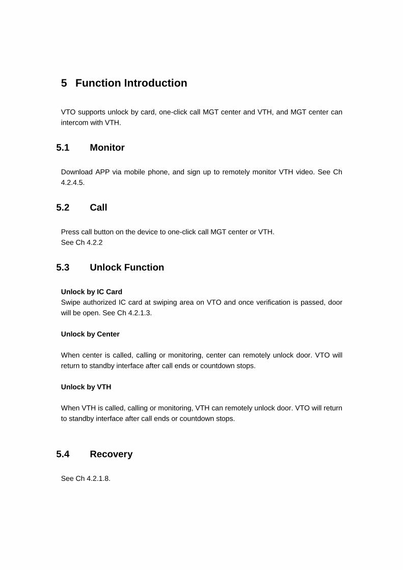
4.4.1 VTH Status
Warning:
If a VTH has never been online, then you cannot find its status in Status Statistics>VTH
Status>VTH Status.
In VTH status, you can view VTH connection status. See Figure 4-23.
Figure 4-23
Status
Offline: Connection between VTO and VTH is disconnected; you cannot call, monitor or
talk.
Online: Connection between VTO and VTH is ready, you can call, monitor and talk.
Monitor Status

Unmom: VTH is not monitoring.
Onmom: VTH is monitoring.
5 Function Introduction
VTO supports unlock by card, one-click call MGT center and VTH, and MGT center can
intercom with VTH.
5.1 Monitor
Download APP via mobile phone, and sign up to remotely monitor VTH video. See Ch
4.2.4.5.
5.2 Call
Press call button on the device to one-click call MGT center or VTH.
See Ch 4.2.2
5.3 Unlock Function
Unlock by IC Card
Swipe authorized IC card at swiping area on VTO and once verification is passed, door
will be open. See Ch 4.2.1.3.
Unlock by Center
When center is called, calling or monitoring, center can remotely unlock door. VTO will
return to standby interface after call ends or countdown stops.
Unlock by VTH
When VTH is called, calling or monitoring, VTH can remotely unlock door. VTO will return
to standby interface after call ends or countdown stops.
5.4 Recovery
See Ch 4.2.1.8.

Appendix 1 Technical Specifications
Model VTO3211D-P2
System Main Process Embedded micro controller
OS Embedded Linux os
Video
Video
Compression
Standard
H.264
Audio
Audio Standard G.711
Input Omnidirectional Mic
Output Built-in speaker
Talk Support bidirectional talk
Operation
Mode Input Mechanical key
Alarm
Input 1-ch unlock button, 1-ch door sensor feedback
Output 1-ch relay output
Front Camera 2.0 MP
Network Ethernet 10M/100Mbps self-fit
Other 485 BUS 1-ch
General
Power DC 12V or standard PoE
Protection IK08
Waterproof IP65
Consumption Standby ≤1W; working ≤7W
Dimension
(L×W×H) 182mm × 30mm × 101mm

1
Note:
This manual is for reference only. Slight difference may be found in user
interface.
All the designs and software here are subject to change without prior written
notice.
All trademarks and registered trademarks are the properties of their respective
owners.
If there is any uncertainty or controversy, please refer to the final explanation of
us.
Please visit our website or contact your local service engineer for more
information.