vr annual progress report 2008 090911 - kth/vr annual progress report... · annual progress report...
TRANSCRIPT

ASSOCIATION EURATOM - VR
Swedish Fusion Research Unit
Annual Progress Report 2008
shutter
cassette holder
Bracket assembly for installation of mirrors
Rotating collector
QMB
Cassette with mirrors

Progress Report 2008 of the Fusion Association EURATOM-VR
2
Cover Pictures: Spectrum sweep demonstrating the MHD controller output tracking capability for the EXTRAP T2R Reversed-Field Pinch experiment. SEM image of impact craters of dust particles in a Silica aerogel collection probe exposed in EXTRAP T2R. Plasma-wall interaction diagnostics installed at JET (a) Different diagnostic tools in the divertor; (b) wall bracket with a cassette with mirrors for the First Mirror experiment and a rotating collector. Compiled from contributions from the research groups of the Swedish Fusion Research Unit James R Drake Head of the Swedish Research Unit Association EURATOM-VR Division of Fusion Plasma Physics Alfvén Laboratory School of Electrical Engineering Royal Institute of Technology KTH SE – 100 44 Stockholm, Sweden

Preface On behalf of the Swedish Fusion Research Unit, I am pleased to present the Annual Progress Report for 2008 covering research carried out under the Contract of Association between the Swedish Research Council (VR) and the European Atomic Energy Community, EURATOM. James R Drake Head of the Swedish Fusion Research Unit Association EURATOM-VR

Progress Report 2008 of the Fusion Association EURATOM-VR
2

Progress Report 2008 of the Fusion Association EURATOM-VR
3
Table of Contents 1 Executive summary …………………………………….
1.1 General introduction 5 1.2 Research Unit 6 1.3 Overview of research activities 7
2 Support advancement of the ITER physics base …….. 2.1 Energy and particle confinement and transport 9 2.2 MHD stability and plasma control 18 2.2.1 Active MHD mode control experiments 18 2.2.2 MHD Stability 24 2.3 Power and particle exhaust, plasma-wall interactions 25 2.3.1 Plasma wall interaction 25 2.3.2 Accelerator-based analysis of materials 38 2.3.3 Studies of dust collection using aerogel collectors 40 2.4 Physics of plasma heating and current drive 41 2.5 Energetic particle physics 49 2.5.1 Energetic particle physics in connection with ICRH 49 2.5.2 Physics of burning fusion plasmas 52 2.5.3 Runaway electrons in tokamaks 52
3 Plasma auxiliary systems – diagnostics ………………. 3.1 Neutron diagnostics 55 3.1.1 Instrument development and characterization 56 3.1.2 Participation in the experimental programme at JET 65 3.1.3 Development of Analysis tools based on Neural Networks 70 3.1.4 JET Neutral particle analyzers 71 3.1.5 R & D for ITER 77 3.2 Plasma spectroscopy 81 3.3 Diagnostic activity at JET 84
4 Concept improvements/fundamental understanding .. 4.1 Development of the reversed-field pinch concept 85 4.1.1 Non-linear MHD dynamics 85 4.1.2 Computational methods with applications for the RFP 90
5 Emerging technology ………………………………… 5.1 High purity ODS-tungsten materials 92 5.2 Material and chemical problems due to corrosion 92 5.3 Waste recycling 93 5.4 Code development 93
6 EFDA JET……………………………………………… 6.1 EFDA JET Orders 94 6.2 JET enhancements 94 6.3 JET campaign participation C20-C25 98 6.4 Fusion Technology at JET 99

Progress Report 2008 of the Fusion Association EURATOM-VR
4
7 EFDA Task Force and Topical Group activity ……… 7.1 Task Force Integrated Tokamak Modelling 100 7.2 Task Force Plasma Wall Interaction 101 7.3 Topical Groups Diagnostics, MHD, Transport 102 7.4 Goal Oriented Training in Theory (GOTiT) 103
8 ITPA activity ………………………………………….. 8.1 Overview of ITPA activity 104
9 Collaborative actions ………………………………… 9.1 Overview of collaborative actions 105
10 Technology …………………………………………….. 10.1 Art. 5.1b actions 106
11 Other activities ………………………………………… 11.1 Training and education 107 11.2 Public information 107
Appendix I Fusion for Energy Grants ………………… 109 Appendix II: Summary Table of EFDA Actions ……… 110 Appendix III: Contact Information …………………… 112

Progress Report 2008 of the Fusion Association EURATOM-VR
5
1 EXECUTIVE SUMMARY 1.1 General introduction Controlled thermonuclear fusion offers the prospect of an intrinsically safe, virtually inexhaustible energy source. It is seen as potentially having a key role in the long-term energy system, primarily for base load electricity production, provided it can be developed to become economically competitive. The next step in the development of a fusion reactor is the ITER experiment. On November 21, 2006 the seven parties, EU, Japan, USA, Russian Federation, China, South Korea and India that collaborate to build and exploit the ITER experiment gathered in Paris to sign the International ITER Agreement on Controlled Thermonuclear Fusion. ITER is being constructed in Cadarache, France. The mission of the ITER experiment is as follows: • Demonstrate capability of steady state fusion power production. • Optimise burning plasma confinement under reactor conditions. • Have dimensions comparable to a power station and produce about 500 MW of fusion
power (10x more power than needed to run it). • Demonstrate or develop new technologies and materials required for fusion power
stations. • Have a construction period of 10 years and an operation period of 20 years.
ITER has been in the planning stages since the 1990s. After a series of pre-agreements, the final ITER International Agreement was signed by the seven international parties. The European Atomic Energy Community (EURATOM) is the Domestic Agency representing the European Union in the ITER International Organisation. A Joint Undertaking for ITER and the Development of Fusion Energy (Fusion for Energy or “F4E”) was approved by the Council of Ministers in 2006 and was formally launched in June 2007. F4E is charged with procurement and delivery of Europe’s contributions to ITER. This signals the start of a new era for fusion research. The development of fusion power is a key action in the European Framework Programme and the research is co-ordinated and managed as a part of the EURATOM agreement. The procurement and delivery of the European contribution to ITER will be the responsibility of the Joint Undertaking. However a substantial support effort is required in the accompanying European fusion programme, which is co-coordinated by the European Commission under EURATOM auspices. The work is performed by various groups in the member states under Contracts of Association. There are additional agreements between the Associations. The European Fusion Development Agreement (EFDA) provides a framework for coordinating activities which compliment the activities of the Joint Undertaking. • Co-ordinated activities in physics and emerging technology. • The collective use of the JET facilities, which is the largest fusion experiment now in
operation and is located in the UK. • Training and career development of researchers, promoting links to universities and
carrying out support actions.

Progress Report 2008 of the Fusion Association EURATOM-VR
6
• European contributions to international collaborations that are outside the Joint Undertaking for ITER and the Development of Fusion Energy.
The long-term strategy of the European fusion programme is based on well-defined steps. Operation of present-generation experiments, in particular the JET experiment, has established a base for the design of ITER. These experiments will now be used to plan for the exploitation of ITER. The results of the ITER project together with efforts carried out in parallel should enable the next step, the construction of a demonstration reactor, DEMO. The focus is now on ITER, however progress to fusion power plants includes additional elements: (i) a test facility for materials, the International Fusion Materials Irradiation Facility, IFMIF, (ii) continued exploration of concept improvements that may, in the longer term, be attractive, and (iii) continued development of the technology required for DEMO and future power plants. The contribution of the Swedish Research Unit to the EURATOM programme is carried out via a Contract of Association between the Swedish Science Research Council (VR) and EURATOM in all of these three areas. The Swedish fusion research unit encompasses a range of competencies that are important for the ITER project and the Association has as its basic goal to make important contributions to the ITER project and to the long term goal of a prototype fusion reactor. 1.2 Research Unit The formation of a Swedish Fusion Research Unit is enabled by a Contract of Association between EURATOM and the VR. Swedish fusion research activities are carried out at four universities and one industry, which together form the Swedish Research Unit (RU). The following universities participate in the fusion research: the Royal Institute of Technology (KTH) in Stockholm, Chalmers University of Technology (CTH) in Göteborg, Uppsala University (UU) and Lund University (LU). A group at Studsvik Energy AB is also a part of the Research Unit. The activity of the Association EURATOM-VR is directed by the Steering Committee, which during 2008 included the following members:
Members: Yvan Capouet (EURATOM), J-J Lopez (EURATOM), Chris Ibbot (first part of year), Ruggero Gianella (second part of year), (EURATOM), Lars Börjesson (VR), Johan Holmberg (VR), Mats Johnsson (Ministry of Education).
HRU: James R Drake (KTH) Secretary: Per Karlsson (VR).
The research activities are carried out within the areas of fusion plasma physics and fusion technology. The fusion plasma physics research is mainly carried out at universities and is concerned with stability, transport, confinement, plasma wall interaction and heating of the plasma and with diagnostic development and implementation. It includes both experimental and theoretical work. A part of the activity within the fusion technology programme is carried out at Studsvik and includes research on materials and ITER reference scenario safety related topics. Fusion technology projects carried out at the universities include in the area of physics integration including studies of confinement, instability control, diagnostic design and plasma facing components which have been initiated at KTH and UU.
Progress Report 2008 of the Fusion Association EURATOM-VR
7
The research activities within the RU are organized in a number of research projects and are well integrated into the EURATOM fusion programme. The activity is a part of the accompanying programme which supports the ITER project. It includes substantial participation in the EFDA JET projects as well as collaboration with other Associations. A special feature of the Swedish fusion Research Unit is that it is university based and involves research student participation and education. 1.3 Overview of research activities The EFDA agreement provides the framework for the co-ordinated European fusion research activity. All the member states with fusion research units participate in EFDA. The EFDA leadership includes the EFDA Leader, Mr. Jerome Pamela and the EFDA Associate Leader for JET, Mr. Francesco Romanelli. The leadership is aided by staff forming Close-Support Units. The EFDA Steering Committee, made up of representatives from the Associations that are members of EFDA, functions as a governing board for EFDA. The instrument for co-ordination of the work is a work plan prepared by the EFDA leadership and approved by the EFDA Steering Committee. The work plan normally spans several years. An annual work programme, based on the work plan, is also prepared by the EFDA leadership and approved by the Steering Committee. The work programme is used as the basis for the annual work programmes prepared for each research unit. The principal areas of the work programme where the Swedish Association focuses its activity are as follows: Support to the advancement of the ITER physics base • Theory and modelling of energy and particle transport in tokamaks. This work is
connected with the EFDA Task Force for Integrated Tokamak Modelling. There is also participation in ITPA activity.
• MHD stability and plasma control, in particular resistive wall modes. Experimental work is carried out on the EXTRAP T2R Reversed-field pinch experiment in collaboration with the RFX experiment in the fusion Association EURATO-ENEA located at Padua, Italy. The group is also collaborating with the ASDEX Upgrade experiment in the fusion Association EURATOM-IPP located at Garching, Germany. The work is connected with the EFDA Topical Group MHD.
• Particle exhaust and in particular related plasma-wall interactions: fuel inventory, development of fuel removal methods and material erosion, migration and re-deposition. This work is connected with the EFDA Task Force on Plasma-Wall Interactions. This work is carried out in collaborations with the TEXTOR experiment, Jülich, Germany and the JET experiment. There is also participation in ITPA and IEA activities. First mirror development is also a part of the programme.
• Theory, modelling and observation of plasma heating and current drive using RF power in the ion cyclotron range of frequencies. The work is done in collaboration with the JET experiment and other European tokamaks and is included in the EFDA Task Force for Integrated Tokamak Modelling.
• Energetic particle physics including collective fast particle effects due to hot ions and alpha particles and supra thermal electrons. The work includes development of a general kinetic theory of relativistic runaway electrons in disruptive plasmas and code simulation to model toroidal Alfven Eigenmode (TAE) dynamics. The work is connected with the EFDA Topical Group MHD.

Progress Report 2008 of the Fusion Association EURATOM-VR
8
Development of plasma auxiliary systems • Development of neutron diagnostic. The Swedish research unit has delivered and
implemented two neutron spectrometers to the JET experiment, MPRu and TOFOR. The work includes development of high-resolution neutron emission spectroscopy for real-time measurement. Other applications include measurement of fusion power.
• Studies of neutron diagnostic for ITER are also undertaken including participation in ITPA diagnostic activity.
• Participation in the EFDA JET Spectroscopy for ITER-like Wall (SIW) diagnostic development in support of the ITER-like-wall enhancement.
• Development and exploitation of spectroscopy on the EXTRAP T2R device. • Development and implementation of plasma wall interaction diagnostics on the JET
experiment. • Development of neutron diagnostics for MAST. • The work is connected with the EFDA Topical Group Diagnostics.
Development of concept improvements • Optimisation of operational regimes in EXTRAP T2R including control of quasi helicity
states. • Numerical studies of the scaling-dependence of plasma fluctuations, beta and energy
confinement in advanced RFP scenarios, including development of new computational tools.
• Theory for stability limits for micro-instabilities to optimise Stellarator confinement properties.
Fundamental understanding of fusion plasmas • Theory support for the research activities in the area of basic fusion plasma confinement
theory. Technology • Emerging technology: 1) High purity ODS-tungsten materials. 2) Material and chemical
problems due to corrosion. 3) Waste recycling. 4) Code development. • Technology programme: 1) Low oxygen powder HIP. 2) Ion loss calculations. 3) ITER
reference scenarios. 4) Effects of copper impurities. 5) Resistive wall modes. 6) Neutron diagnostic design for ITER. 7) Manufacture of Beryllium coatings.
The major specialised equipment used by the Association includes the following: The EXTRAP T2R reversed-field pinch is located at KTH. The UU group has delivered neutron spectrometers to JET (MPRu and TOFOR). The Association has extensive participation in EFDA-JET through secondments, involvement in JET enhancements and the JET technology programme, and through participation in experimental campaigns. The Association also participates in the two established EFDA Task Forces; Integrated Tokamak Modelling (TF-ITM) and Plasma Wall Interaction (TF-PWI) as well as the EFDA Topical Groups.

Progress Report 2008 of the Fusion Association EURATOM-VR
9
2 Support advancement of the ITER physics base 2.1 Energy and particle confinement and transport J. Weiland, T. Fülöp, A. Jarmén, H. Nordman, V. Pavlenko, I. Pusztai, P. Strand, M. Tendler, Annika Eriksson, Ansar Mahmood, Hans Wilhelmsson Summary The transport work during 2008 includes effects of plasma flows, momentum transport, particle transport, fluid closure, edge plasma physics and detailed geometry effects1-20 (see reference list at the end of this section). Our model has developed further, including transport of toroidal and poloidal momentum. The most recent version was tested against experiment and against the model from 1995 in order to form a part of the new Multi Mode Model (MMM) 2008. The results were published in PoP1. We have also continued to work on Predictive Transport Simulations, Transport Modelling and Transport Theory. We have participated in the ITPA (International Tokamak Physics Activities) Expert group meetings and the EFDA-JET programme and the Integrated Tokamak Modelling Task force (ITM-TF). ITPA work We have participated in the ITPA Transport and ITB and Confinement, Modelling and Database topical groups in Oak Ridge where results on momentum transport were presented. For the ITPA work the emphasis has been on the spinup of poloidal momentum in ITB. Good agreement was obtained in some cases where the ITG mode was stable in the transport barrier region while the trapped electron mode was governing the transport. We have now derived also the off diagonal elements from the stress tensor (IAEA 2008), thus now using only fluid theory. A new numerical scheme has made the code more stable and we can now simulate the spinup of poloidal momentum dynamically. A new model for toroidal momentum transport, including magnetic curvature effects for both diagonal and convective transport elements was introduced. The convective parts were taken from the derivation by T.S. Hahm. The toroidal effects increased both the diagonal and pinch parts, leaving the total stationary transport almost unchanged, i.e. with good agreement with experiment. JET work Our transport model has continued to give good results in comparisons with experiment in connection with our work under the EFDA-JET 2008 programme. This has been mainly on transport of toroidal momentum where our new model, including toroidal effects from the stress tensor both for diagonal and off diagonal transport elements has given good agreement with stationary transport while now also the transient transport is improving. Another area where good results were obtained is that of high beta experiments (Laborde et. al. Phys. Plasmas 15, 102507 (2008)). Our JET work has focused on momentum transport. In particular good results were obtained for toroidal momentum transport where the Prandtl number (ratio of momentum diffusivity to ion thermal conductivity) has been in good agreement with JET experiments in various

Progress Report 2008 of the Fusion Association EURATOM-VR
10
parameter regimes. The trend that the Prandtl number increases towards the edge is also in agreement with experiments. The simulations of the spinup of poloidal rotation have continued for a new shot and are still successful. A simulation at a time just before a barrier showed that the poloidal rotation in the simulation has a tendency to proceed the experimental. These results are, of course, very sensitive to several details in the simulations and the only conclusion we can draw now is that we are close to describing the actual experimental dynamics. The simulations of toroidal rotation, now using the new model, have continued to give good agreement with the stationary rotation. We have here also simulated a shot with torque modulation and here it appears as if we need an even larger diagonal element. Extensive tests were also made of the code against the JETTO code for fixed transport coefficients. The most recent result is a simulation of the formation of a transport barrier on JET including four channels: ion and electron temperature and poloidal and toroidal momentum. No barrier was included in the initial condition and the location of the barrier was given by the minimum in q (q=2). The result, including the spinup of poloidal momentum, was in rough agreement with the experiment. P. Strand and T. Jonsson have contributed to the Integration of Transport and MHD codes project led by Vassili Parail. This work aims at upgrading the modelling capability of transport code implementations and has been in providing modular physics components facilitating verification and validation benchmarking on improved physics. Simulations of toroidal momentum transport by the MMM08 The new model for momentum transport in our model has also given good results in simulations by the Lehigh group using the MMM08. In particular the agreement with experiment was better than for the GLF23 model. Integrated Tokamak Modelling Task Force (ITM-TF) The European Task Force on Integrated Tokamak Modelling has the mid- to long-term goal of providing a validated suite of software tools for ITER exploitation. P. Strand is as of October 2006 the Task Force Leader. The work within the Task Force has progressed rapidly in several areas and the ITM has been starting to have an impact in the broader fusion community and are actively taking part in the development on the broader modeling programme in Europe. In addition, VR is represented by T. Hellsten as the project leader in the Heating & Current Drive project (Integrated Modelling Project #5 - MP#5) – coordinating the physics and modeling development in that area. Active participation in the projects outside of the leadership functions above is in IMP#5, Non-linear MHD (IMP#2) and to a lesser extent in the Turbulence and Transport project (IMP#4) together with a somewhat smaller contribution to the IMP#3 (transport code and whole device project). During 2007 resources were provided to coordinate a proposal under the EU Seventh Framework Capacities programme. This has lead to the EUFORIA project being funded at 3.65 M Euro during the three year period starting January 2008 with Chalmers being acting coordinator and the Chalmers part shared between RSS and C3SE.

Progress Report 2008 of the Fusion Association EURATOM-VR
11
Theory-Effects of plasma flows on transport Transport Barriers in Fusion Devices The radial velocities and radial scale lengths of high-density (turbulence-induced) filaments, named blobs, in the peripheral region of the High Field Side of the FT-2 tokamak are obtained using data from Langmuir probes set measurements. The experimental results are compared with existing theoretical models. The magnitude of values found are comparable with the proposed models though the agreement with the predicted dependence between blob sizes and blob velocities is only in agreement with the analytical expression derived for the ballooning modes. We observe as well blobs with movement both in inward and outward radial direction, which is not yet understood theoretically since only the outward direction is explained. Momentum transport Our new model for the off diagonal elements of momentum transport uses only fluid theory and includes curvature effects from the stress tensor. Agreement has been obtained for the main terms of Peeters and Hahm. This model also includes the nonlinear generation of flows (zonal flows) by the turbulence. This effect is particularly strong with our closure. In particular we have the only transport code which, so far, has recovered the experimental magnitude of the poloidal “spinup” of rotation in transport barriers. This is due to zonal flows, which, in turn, are due to a space dependent nonlinear frequency shift. This is a strongly nonlinear effect so our model is no longer quasilinear. During 2008 extensive work has been done on simulations of momentum transport. A recent development of our work on statistical physics in collaboration with the Bogoliubov Institute of Theoretical Physics is the inclusion of flowshear. There the Waltz rule for stabilization of turbulence by flow shear in the nonlinear regime was recovered. Transport in systems with several types of free energy. A presentation was given at ICTP Trieste in July on the physics of thermal and particle pinches. Here the description for the particle pinch was new. It was also pointed out that the reason why transport coefficients grow with radius in our model is a coupling between gradients in temperature and magnetic field. Basic nonlinear phenomena and nonlinear structures A new analytic study was made of the nonlinear excitation of zonal flows and Geodesic Acoustic modes. Such effects are also naturally present in our transport code, in particular in connection with the spinup of poloidal rotation. Also vortex dynamics has been studied by a nonlinear analytic model of reaction diffusion equations. The main applications have been to the thermalisation of alpha particles and to the expansion of the universe. Our collaboration with the Bogoliubov Institute for Theoretical Physics on statistical problems has continued with studies of particle trapping, flowshear, partly coherent situations19 and fluid closure.
Theory-Linear eigenvalue problems The Eigenvalue problem for electrostatic resistive edge modes has been solved numerically using the Ballooning formalism and full numerical (VMEC) equilibria corresponding to ITER scenario-4 and W7-X stellarator. In comparison to the stellarator equilbrium, a stronger FLR stabilization and a more narrow mode spectrum was found in the tokamak equilbrium, which might be due to the presence of a significantly larger magnetic shear and a less unfavorable normal curvature on the chosen magnetic flux surface of the tokamak. While increasing ion

Progress Report 2008 of the Fusion Association EURATOM-VR
12
temperature gradients leads to the FLR stabilization of the strong resistive ballooning modes, it was found that this FLR stabilization requires higher values of ion temperature gradients in the stellarator case than those in the tokamak. Another study in ITER equilibrium was made in the collisionless case including also electron trapping. The dependence of stability on local and global shear and on normal and geodesic curvature was studied. Here the dependence of magnetic shear of the ITG mode was transferred to the TE mode due to linear couplings. The dependence of temperature ratio showed a rather complicated dependence on parameter regime. Parallel ion dynamics and electromagnetic perturbations in an advanced fluid model. Ion dynamics parallel to the background magnetic field and electromagnetic perturbations have been taken into account at the same time. The derivation gives two coupled second order differential equations in the electrostatic and magnetic potentials. A numerical code based on the shooting technique has been developed and tested with promising results. The solution of the equations is expected to add new information about mode structure and stability thresholds based on the advanced fluid model. The code has developed further during 2008 and the first results are expected during 2009. Theory-Particle transport Kinetic effects on the main particle pinch A very interesting feature of particle transport is the possibility of particle pinches. These could improve the performance of ITER strongly. During 2008 we have investigated effects of fluid closure on particle pinches. Our fluid closure is presently the model with the strongest particle pinches. It has recently been found that kinetic models without nonlinearities that can counteract linear wave particle resonances, cannot support the steep density profile in Ohmic JET shots. However, our model has been successful in simulating such shots. In order to investigate this we have added kinetic “gyrofuid” resonances to our model. The result was that the particle pinch was strongly reduced and the peaked experimental density profile in a JET shot could not be supported. Quasilinear kinetic code We have now also developed a quasilinear kinetic code where the kinetic integral has been evaluated analytically. Here we can turn the kinetic resonances “on” and “off” in order to see their influence on the particle pinch. As expected the particle pinch is considerably weaker in the quasilinear model than in gyrofluid models. Our reactive fluid model, however, has the strongest particle pinch. This work involves collaboration with Culham laboratory, including Yueqiang Liu who was formerly part of our group and is now an Adjunct Professor at Chalmers.

Progress Report 2008 of the Fusion Association EURATOM-VR
13
Fig. 2.1-1 Effective particle diffusivity for the fluid (blue) and the kinetic (red) model; the ITG (solid) and TE (dotted) eigenvalues are also shown. Density and temperature length scales as well as trapped electron fraction and temperature ratio are varied around the standard case parameters. We note the strong tendency for linear kinetic resonances to reduce the particle pinch. This can be understood from the point of view that linear kinetic resonances introduce irreversibility while pinches are reversible phenomena. Impurity transport We have studied transport of impurity ions and the results of our fluid model have been compared with nonlinear gyrokinetic results using the code GYRO. The results are usually very similar with a typical deviation of about a factor of two in the fluxes. Comparisons between fluid and gyrokinetic anomalous transport predictions and neoclassical transport were also performed for a reference hybrid-mode ITER plasma. This work was performed as part of the collaboration between the Transport Theory Group, the Nonlinear Electrodynamics Group (T. Fülöp) and J. Candy (GA, USA)

Progress Report 2008 of the Fusion Association EURATOM-VR
14
Fig. 2.1-2 Comparison between the fluid model developed at Chalmers (QFM), nonlinear gyrokinetic simulations (GYRO) and gyrofluid (TGLF) results for impurity particle transport obtained for a hybrid-mode ITER scenario. The impurity particle flux versus normalised minor radius is shown for impurity charge Z=6. From [J. Candy et al, Proc of IAEA Fusion Energy Conf TH/P8-28, Geneva (2008)]. The effect of the ponderomotive force due to radio frequency fields on impurity transport has been studied. It was shown that the impurity pinch can be affected by the ponderomotive force and by the nonlinear interaction between the fast magnetosonic wave and ITG modes.
Fig.2.1-3. Impurity diffusion coefficient DZ, convective velocity RVZ and impurity peaking factor as a function of the ponderomotive force term for an ITG mode dominated case [2]. Collisionality dependence of the quasilinear particle flux due to microinstabilities The collisionality dependence of the quasilinear particle flux due to the ion temperature gradient ITG and trapped electron mode TEM instabilities is studied by including electron collisions modelled by a pitch-angle scattering collision operator in the gyrokinetic equation. The inward transport due to ITG modes is caused mainly by magnetic curvature and

Progress Report 2008 of the Fusion Association EURATOM-VR
15
thermodiffusion and can be reversed as electron collisions are introduced, if the plasma is far from marginal stability. However, if the plasma is close to marginal stability, collisions may even enhance the inward transport. The sign and the magnitude of the transport are sensitive to the form of the collision operator, to the magnetic drift normalized to the real frequency of the mode, and to the density and temperature scale lengths. These analytical results are in agreement with previously published gyrokinetic simulations.
Fig. 2.1-4 Quasilinear particle flux as a function of collisionality. [a,b]: Comparison of results using pitch-angle scattering (red) and Krook (black) collision operators for three different values of magnetic drift frequency. [c,d]: Comparison of our semi analytical model (black) to linear GYRO simulations (blue) in terms of particle flux [c] and mode frequencies (solid) and growth rates (dashed) [d]. In [c], the dotted line shows the result when the collisionality dependence of the eigenfrequency is neglected, while in [d] the thick and thin lines correspond to different electron-to-ion temperature ratios. Publications section 2.1 Peer reviewed journals
1. F.D. Halpern, A. Eriksson, G. Bateman, A.H. Kritz, A. Pankin, C.M. Wolfe and J. Weiland, Improved model for transport driven by drift modes in tokamaks, Phys Plasmas 15, 012304 (2008).
2. H. Nordman, R. Singh, T. Fülöp, L.-G. Eriksson, J. Andersson, P. Strand, M. Tokar and J. Weiland, Influence of the RF Ponderomotive force on the Anomalous Impurity Transport in Tokamaks, Phys. Plasmas, 15, 042316 (2008).
3. D. Strinzi, A. Peeters and J. Weiland, The toroidal momentum diffusivity in a tokamak plasma; a comparison of fluid and kinetic calculations, Phys. Plasmas 15, 044502 (2008).

Progress Report 2008 of the Fusion Association EURATOM-VR
16
4. V.I. Zasenko, A.G. Zagorodny and J. Weiland, Particle Trapping and Non-Resonant Interaction in a Problem of Stochastic Acceleration, Ukrainian Journal of Physics 53, 517 (2008).
5. M.A. Mahmood, T. Rafiq, M. Persson and J. Weiland, Resistive edge mode instability in stellarator and tokamak geometries, Phys. of Plasmas 15, 092507 (2008).
6. T. Fülöp, I .Pusztai and P. Helander, Collisionality dependence of the quasilinear particle flux due to microinstabilities, Phys. Plasmas 15, 072308 (2008).
Invited talks at international conferences and workshops.
7. J. Weiland, Relaxation in systems with several types of free energy, Invited lecture, International Workshop on the Frontiers of Modern Plasma Physics, International Centre for Theoretical Physics, Trieste, Italy, July 14-25 (2008).
Talks at ITER and ITPA workshops
8. J. Weiland, T. Tala, P. Mantica, K. Crombe, V. Naulin, A. Peeters, D. Strintzi and the JET-EFDA Contributors. Predictive simulations of Spontaneous Rotation in JET. Presented at the 14th ITPA meeting in Oak Ridge, April 22-25 2008.
Presentations at EPS conferences
9. M.A. Mahmood, J. Weiland, M. Persson, et al. (2008). Study of collisionless TE and ITG modes in an ITER-like equilibrium, 35th EPS Conference on Plasma Physics, Hersonissos (Greece), P-4.024.
10. H. Nordman, R. Singh, T. Fülöp, et al. (2008). Anomalous impurity transport in tokamaks in the presence of RF fields, 35th EPS Conference on Plasma Physics, Hersonissos (Greece), P-2042.
11. S. Moradi, D. Kalupin, H. Nordman, R. Singh, M. Tokar, B. Weyssow, (2008). Modeling of confinement improvement and impurity transport in high power JET H-mode discharges with neon seeding, 35th EPS Conference on Plasma Physics, Hersonissos (Greece), P4.048.
12. Eriksson, J. Weiland, Y. Liu and L. Garzotti, Resonance effects on turbulent particle pinches, 35th EPS Conference on Plasma Physics, Hersonissos (Greece), P-1.048.
13. D. Strintzi, A.G. Peeters and J. Weiland, The Toroidal Momentum Diffusivity in a Tokamak Plasma; A Comparison of Fluid and Kinetic Calculations, 35th EPS Conference on Plasma Physics, Hersonissos (Greece), P-2.032.
14. Pusztai, T. Fülöp, and P. Helander, On the quasilinear transport fluxes driven by microinstabilities in tokamaks, 35th EPS Conference on Plasma Physics, Hersonissos (Greece), P1.032.
Presentations at IAEA conferences
15. J. Weiland, R. Singh, H. Nordman, P. Kaw, A. Peeters and D. Strintzi, Symmetry breaking effects on toroidal momentum transport, TH/P8-29, IAEA, Geneva 2008.
16. G. Bateman, F.D. Halpern, A.H. Kritz, A.Y. Pankin, T. Rafiq, R.V. Budny, D.C. McCune, J. Kinsey, I. Voitsekovich, J. Weiland and the JET-EFDA contributors, Integrated Modeling Simulations of Toroidal Momentum Transport in Tokamaks, TH/P8-35, IAEA, Geneva, 2008.
17. R. Singh, R. Goswami, R. Ganesh, P.K. Kaw, J. Weiland and P.N. Guzdar, Nonlinear Excitation of Zonal Flows and Geodesic Acoustic Modes in the Edge of Tokamak Plasma, TH/P8-14, IAEA, Geneva, 2008.

Progress Report 2008 of the Fusion Association EURATOM-VR
17
18. L.G. Eriksson, H. Nordman, R. Singh, T. Fülöp, R. Dumont, P. Kaw, P. Strand, M. Tokar and J. Weiland, Influence of RF Fields on Anomalous Impurity Transport in Tokamaks, TH/P8-8, IAEA, Geneva, 2008.
19. H. Nordman, J. Candy, M. Fahey, T. Fülöp, E. Belli, Transport in ITER-like plasmas in neoclassical, fluid and gyrokinetic descriptions, TH/P8-28, IAEA, Geneva, 2008.
20. T. Fülöp, I. Pusztai, P. Helander, Quasilinear transport fluxes driven by electrostatic microinstabilities in tokamaks, TH/P8-28, IAEA, Geneva, 2008.
Other workshops and conferences
21. J. Weiland organized a Miniworkshop on Stochastic Processes and Transport at Chalmers on May 29 2008. Presentations by Imre Pázsit , Magnus Willander, Mohammad Asadzadeh, Anatoly Zagorodny, Vladimir Zasenko and Jan Weiland.
22. Zagorodny, and J. Weiland, Non-Markovian Fokker-Planck equation and renormalisation of drift wave turbulence, Miniworkshop on Stochastic Processes and Transport, Chalmers University of Technology, May 29 2008.
23. V. Zasenko, A. Zagorodny, and J. Weiland, Generalisation of the Fokker-Planck Equation for Plasma with Random Field of Moderate Intensity, Miniworkshop on Stochastic Processes and Transport, Chalmers University of Technology, May 29 2008.
24. J. Weiland, A. Zagorodny and V. Zasenko, Fluid closure for times larger than the confinement time in bounded systems, Miniworkshop on Stochastic Processes and Transport, Chalmers University of Technology, May 29 2008.
25. Pusztai, T. Fülöp, P. Helander, Quasilinear transport fluxes driven by electrostatic microinstabilities in tokamaks, 13th EU-US TTF Workshop, Copenhagen 2008.
26. T. Fülöp, I. Pusztai, P. Helander, J. Candy, H.Nordman, Quasilinear transport fluxes driven by ion temperature gradient modes in tokamaks, oral presentation at the Hungarian Plasma Physics Workshop, Györ 2008
27. T. Fülöp, I. Pusztai, P. Helander, Collisionality dependence of quasilinear transport driven by microinstability, Wendelstein-seminar, Greifswald 2008.

Progress Report 2008 of the Fusion Association EURATOM-VR
18
2.2 MHD stability and plasma control 2.2.1. Active MHD mode control experiments P. Brunsell, E. Olofsson (PhD student), M.W.M. Khan (PhD student), L. Frassinetti, J. R. Drake In collaboration with: W. Suttrop, D. Yadikin, Max-Planck-Institut für Plasmaphysik, Garching, T. Bolzonella, R. Paccagnella, G. Manduchi, RFX Team, Consorzio RFX, E. Witrant, UJF-INPG/GIPSA-Lab, Grenoble, France, H. Hjalmarsson, E. Jacobsen, EES/Automatic Control, KTH The general goal of the present research program on RWM physics and feedback control is the development of advanced control approaches that are applicable to both tokamak and RFP. There is also a specific aim to develop a controller design for the planned experiments on active RWM stabilization at ASDEX Upgrade, which is carried out in collaboration with Max-Planck-Institute für Plasmaphysik and Consorzio RFX. EXTRAP T2R device The research program at the EXTRAP T2R reversed-field pinch device is focused on MHD instability control and non-linear MHD dynamics. A system for active control of non-axisymmetric MHD modes was developed at EXTRAP T2R during 2004-2005 in collaboration with Consorzio RFX. The Active MHD Mode Control System installed EXTRAP T2R has capabilities that in conjunction with other attractive features of the experiment provides excellent capabilities for research on MHD instability control.
Figure 2.2-1. The EXTRAP T2R device at the Alfvén Laboratory.
The EXTRAP T2R device, shown in Fig. 2.2-1, has a close-fitting shell made of thin copper plate for ideal MHD mode stabilization. The shell magnetic flux penetration time is short compared to the plasma life time, which enables study of resistive wall mode stability and control methods.

Progress Report 2008 of the Fusion Association EURATOM-VR
19
A number of diagnostics systems are installed on EXTRAP T2R. The main emphasis is on magnetic diagnostics. A total of around 900 magnetic sensors have been installed on the vessel surface inside the conducting shell. These sensors are part of a comprehensive diagnostic system for studies of MHD instabilities and active MHD mode control. It consists of pick-up coils for the measurement of the poloidal, toroidal and radial components of the magnetic field at 4 poloidal and 64 toroidal positions. The data acquisition system limits the number of signals that can be collected in each pulse. The list of plasma diagnostics installed on EXTRAP T2R include
• Electric and magnetic probe array for turbulence studies. • Collector probes for plasma wall interaction studies. • VUV and visible spectroscopy. • Thomson scattering. • Interferometer. • Neutral particle time-of-flight diagnostic. • Bolometer array. • SXR camera.
A single-point single-time Thomson scattering system provides the absolute value of the electron temperature in the 50 – 500 eV range and the electron density in the plasma centre. The neutral particle analysis system, based on the time-of-flight technique, provides the ion central temperature as well as the charge-exchange neutral fluxes. An 8-chord bolometric system, based on gold thin film detectors, is used to measure the radial profile of plasma radiation losses in the UV-SXR wavelength range. A single line-of-sight two-color interferometer (CO2 and HeNe) is used to measure the line integrated electron density along the plasma diameter. The SXR camera system consists of 12 line-of-sights that look at the plasma from the outboard side towards the inboard side covering 80 % of the plasma poloidal cross section. Table 2.2-1. EXTRAP T2R machine and plasma parameters Parameter Notation Value UnitMajor radius R 1.24 m Minor radius a 0.183 m Wall diffusion time τv 6.3 ms Plasma pulse length τd <100 ms Plasma current (typical) Ip 100 kA Plasma electron temperature (typical) Te 300 eV Plasma electron density (typical) ne 1x10¹⁹ m-3 Active MHD mode control system The active MHD mode control system installed on EXTRAP T2R is based on extensive arrays of active coils and sensors distributed over the toroidal surface as shown in Fig. 2.2-2. The main features of the active control system are: • A two-dimensional array of radial magnetic flux loop sensors at 4 poloidal and 32 toroidal
positions, a total of 128 sensors. • A two-dimensional array of active saddle coils at 4 poloidal and 32 toroidal positions
outside the resistive wall, a total of 128 coils.

Progress Report 2008 of the Fusion Association EURATOM-VR
20
• A set of power amplifiers units providing at total of 64 independent channels. Saddle coils and sensor flux loops are pair-connected at each toroidal position to form 64 independent m=1 coils and sensors.
• An integrated digital computer based controller unit. Professional audio amplifiers are used with output power of 800-1200 Watt and bandwidth 1 Hz to 25 kHz. Amplifier output currents are up to 20 A, providing 800 At in the power coils and a maximum radial magnetic field at the coil centre of about 3 mT. The integrated controller unit is contained in a VME bus crate and includes ADCs for analogue input of 64 magnetic sensor signals and 64 coil current signals, Board with PPC CPU, DACs for analogue output of 64 amplifier control voltages. Controller algorithms are implemented in software.
RWM feedback control The basic philosophy is to develop RWM stabilization from the viewpoint of process control, thereby gaining access to a number of tools that have been developed in this field over many years. The engineering approach assumed is following the process control methodology: system identification, selection of feedback interconnections, and subsequently controller design and tuning. The scope of the research is wide: modelling, mode identification, input design, real-world implementation and conduction of the physical experiment; reflecting the possibilities for new ideas and progression in control-oriented fusion research. Closed loop RWM identification experiments A method for efficiently measuring the plasma response to external fields is desired. This method runs parallel with RWM stabilization and dedicated open-loop plasma response shots are not required. The procedure is known in automatic control as closed-loop system identification. A structured and parametric RFP model for RWMs is assessed with three main purposes: 1) experimental MHD stability research, 2) prospecting identification for control and reconfiguration of the stabilizing circuit, and 3) development of generally useful identification methods and perturbation designs. The first step is to perform experiments to identify the external plasma response by pseudo-randomly perturbing it, while simultaneously
Figure 2.2-2. Two-dimensional arrays of sensor flux loops and active saddle coils installed at EXTRAP T2R.

Progress Report 2008 of the Fusion Association EURATOM-VR
21
stabilizing the plasma using established intelligent shell operation. In a second phase, the identification procedure is further developed by using the physics-based parametric cylindrical MHD model of the RWM instability in combination with the convex programming experiment design method. Success in this study has two significant spin-offs: 1) tailored control system reconfiguration/reimplementation, 2) testing of electromagnetic shell-plasma models. Large part of the work is directly applicable also to tokamak.
Model-based controller design for output tracking A major step in RWM stability research is the development of model based control systems, both design evaluations and experimental deployment. Already, this has been partially achieved for the RFP configuration by the Clean-Mode-Control concept, conceived and operated at RFX, which handles spatial aliasing effect introduced by the sensor and actuator arrays. An extension of this idea has been studied, based on a dynamical model of the external plasma response. The aim is the development of a control system design for output tracking, and implementation and testing the system at EXTRAP T2R. In this context, output tracking is considered as a generalization of the original intelligent shell concept, which enables the control system not only to suppress modes, but also to sustain MHD modes in closed-loop operation. In principle, by active feedback, the plasma can be forced to user-specified helicities of prescribed amplitudes and phases. The controller design will be a versatile tool for experimental plasma dynamics and innovative RWM stability research. The model is developed using a state-space representation. An explicit multiple-input-multiple-output (MIMO) model for the vacuum field diffusion is used. Together with knowledge of the actuator dynamics it provides the essential information required for nominal tuning of the output-tracking control system. The model is assembled from multiple-input-single-output (MISO) identification sub-problems, for which also is needed the single-input-single-output (SISO) identification results of the actuator dynamics. The actuator dynamics SISO model contains the active coil, power amplifier and control system delay.
Figure 2.2-3. Dithering signal applied to active coils for closed-loop RWM identification experiments.

Progress Report 2008 of the Fusion Association EURATOM-VR
22
Figure 2.2-4. Spectrum sweep demonstrating the controller output tracking capability.
Controller design with time-delay compensation The aim of this project is to introduce and analyze a new model for RWM stabilization that takes into account sensors/actuators aliasing, actuator dynamics, and control time-delays. The model is then utilized to develop a model-based controller design that includes time-delay compensation. The approach, which takes into account the time-delays due to the control implementation, leads to a multi-variable time-delay model of the system. The importance of the delay effects can readily be investigated by performing a stability analysis of the resulting closed-loop delay differential equation (DDE). Based on the model, a structurally constrained optimal controller is then designed. The controller parameters can be determined using the method of direct Eigenvalue optimization of the DDE. Data driven controller tuning The objective is to improve a baseline mode controller, prepared in some way related to identification data, and physical modelling. Having set up this nominal controller, it might be possible to optimize and more fully adapt it to experimental conditions. The tuning method is nonmodel-based, primarily concerned with structure, iteratively modifying the arguments of a cost function so that the output of the cost function reaches a local minimum or local maximum. Iterative feedback tuning and extremum-seeking are related methods that will be assessed for applicability to the T2R plant. Development of RWM control at ASDEX Upgrade ASDEX Upgrade enhancement project for active MHD control is collaboration between IPP, Consorzio RFX and KTH. A set of 3x8 in-vessel saddle coils have been designed by IPP for the ASDEX Upgrade tokamak. The coils are to be used in future RWM stabilization experiments on the device. Expressions for the linear response of various components in the RWM control loop have been obtained by IPP. The description will be input to the RWM control design.

Progress Report 2008 of the Fusion Association EURATOM-VR
23
Publications section 2.2.1 Peer reviewed journals
1. E. Olofsson and P. Brunsell, “Controlled magnetohydrodynamic mode sustainment in the reversed-field pinch: Theory, design and experiments”, in press: Fusion Eng. Des. (2008).
2. W. Suttrop, O. Gruber, S. Günter, D. Hahn, A. Herrmann, M. Rott, T. Vierle, U. Seidel, M. Sempf, B. Streibl, E. Strumberger, D. Yadikin, O. Neubauer, B. Unterberg, E. Gaio, V. Toigo, P. Brunsell, the ASDEX Upgrade Team, “In-vessel saddle coils for MHD control in ASDEX Upgrade”, in press: Fusion Eng. Des. (2009).
Conference contributions with proceedings
3. W. Suttrop, M. Rott, T. Veirle, B. Streibl, A. Herrmann, V. Rohde, U. Seidel, D. Yadikin, O. Neubauer, B. Unterberg, E. Gaio, V. Toigo, P. Brunsell, ASDEX Upgrade Team, “Design of in-vessel saddle coils for MHD control in ASDEX Upgrade”, Proc. 35th EPS Conference on Plasma Phys. Hersonissos, 9-13 June 2008, Europhysics Conf. Abstracts Vol. 32D, P-4.075 (2008).
4. E. Olofsson, E. Witrant, C. Briat, S.-I. Niculescu, and P. Brunsell, “Stability analysis and model-based control in EXTRAP T2R with time-delay compensation”, Proc. 47th IEEE Conference on Decision and Control (CDC 2008), Cancun, Mexico, Dec 9-11, 2008, p. 2044-2049.
5. J R Drake, T Bolzonella, K E J Olofsson, T M Baruzzo, P R Brunsell, L Frassinetti, S C Guo, V Igocine, Y Q Liu, G Marchiori, R Paccagnella, G Rubinacci, A Soppelsa, F Villone, D Yadikin, P Martin, H Zohm, “Reversed-Field Pinch Contributions to Resistive Wall Mode Physics and Control”, Proc. 22nd IAEA Fusion Energy Conference 13-18 October 2008, Geneva, Switzerland, IAEA-F1-CN-165, Paper EXP/P9-7.
6. E. Olofsson and P. Brunsell, “Closed-loop identification and controller reconfiguration for EXTRAP-T2R reversed field pinch”, accepted to 36th Symposium on Fusion Engineering (ICOPS/SOFE 2009), San Diego, California, May 31- June 5, 2009, paper no 1029.
7. E. Olofsson, P. Brunsell, and J. Drake., “Closed-loop direct parametric identification of magnetohydrodynamic normal modes spectra in EXTRAP T2R reversed-field pinch”, accepted to 3rd IEEE Multi-conference on Systems and Control (MSC 2009), Saint Petersburg, July 8-10, 2009.
8. E. Olofsson, H. Hjalmarsson, C. R. Rojas, P. Brunsell, and J. R. Drake., “Vector dither experiment design and direct parametric identification of reversed-field pinch modes”, submitted to 48th IEEE Conference on Decision and Control (CDC 2009), Shanghai, China, Dec. 16-19, 2009.
9. W. Suttrop, D. Hahn, A. Herrmann, M. Rott, B. Streibl, W. Treutterer, T. Vierle, D. Yadikin, I. Zammuto, E. Gaio, V. Toigo, P. Brunsell, E. Olofsson, and the ASDEX Upgrade Team, “Physical description of external circuitry for Resistive Wall Mode control in ASDEX Upgrade”, submitted to 35th EPS Conference on Plasma Phys., Sofia, Bulgaria , June 29 – July 3, 2009

Progress Report 2008 of the Fusion Association EURATOM-VR
24
2.2.2 MHD stability C. Wahlberg Collaboration with: Jonathan Graves CRPP Lausanne and Ian Chapman UKAEA Culham Analysis of infernal and electron fishbone modes in low-shear tokamaks In collaboration with Dr. Jonathan Graves, CRPP Lausanne, we are developing analytical theory of infernal modes in tokamak plasmas with an extended region of low magnetic shear, including the quasi-interchange mode in low-shear plasmas with q ≈ 1 in the core region. Progress has made in the MHD description of these modes, in particular an extension of a previously derived analytical stability criterion valid for a parabolic pressure profile to general pressure profiles. Our aim is to include also kinetic effects in order to model electron fishbone modes seen in the TCV tokamak, and progress has been made also in this area during 2008. A first report is expected in 2010. Analytical and numerical studies of internal kink mode stability in rotating tokamak plasmas In collaboration with Dr. Ian Chapman, UKAEA Culham, and Dr. Jonathan Graves, CRPP Lausanne, we are investigating the m = n = 1 stability of toroidally rotating tokamak plasmas, using a combination of analytical theory and numerical computation. We are especially focusing on the role played by the centrifugal effects on the plasma equilibrium, i.e. the enhanced Shafranov shift and the nonuniform plasma density and pressure created on the magnetic surfaces by the rotation. Analytically, the centrifugal effects are studied by means of a model equilibrium where these two effects can be switched on and off, and numerically we are using two different codes; one code where the centrifugal effects are not included in the equilibrium (MISHKA-F) and another where these effects are included self-consistently in the equilibrium (CASTOR-FLOW). The results show a very strong and stabilizing effect from the centrifugal effects also at relatively moderate flow speeds of the plasma. For sufficiently large aspect ratio we also find a very good agreement between the numerical and analytical results. This collaboration was initiated mid 2008, and first results will be reported during 2009. Geodesic acoustic modes (GAM) in toroidally rotating tokamak plasmas The geodesic acoustic modes (GAMs) are presently of very large theoretical and experimental interest in tokamak physics. The mode plays, for instance, an important role in connection with turbulent transport, and it determines the low-frequency limit of the frequency sweep of the Alfvén cascades occurring in tokamak plasmas with reversed magnetic shear. It was shown in 2008 within this project that toroidal plasma rotation increases the (Doppler-shifted) frequency of the original GAM and, more importantly, induces a second GAM, with a frequency much lower than the ordinary GAM frequency (see ref [1] this section). Both of the GAMs in rotating plasmas are shown to exist both in the form of continuum modes with finite mode numbers m and n at the resonant surfaces q = m/n as well as in the form of axisymmetric modes with m = n = 0. In the limit of zero rotation frequency, the axisymmetric form of the rotation-induced GAM becomes identical to the zonal flow eigenmode, which accordingly is transformed to a mode with finite eigenfrequency in a toroidally-rotating plasma. More recently, this theory has been further developed and extended, including an analysis of the radial structure of both axisymmetric GAMs in a rotating plasma, and a longer version of [1] is presently being considered for publication in Plasma Physics and Controlled Fusion.

Progress Report 2008 of the Fusion Association EURATOM-VR
25
Publications section 2.2.2 Peer reviewed journals 1. Wahlberg, C., " Geodesic Acoustic Mode Induced by Toroidal Rotation in Tokamaks",
Phys. Rev. Lett, 101, 115003, 2008. 2.3 Power and particle exhaust, Plasma-wall interactions 2.3.1 Plasma-wall interactions M. Rubel, B. Emmoth, P. Sundelin (PhD student) Beryllium coatings and marker tiles for the ITER-Like Wall at JET To achieve further progress in controlled fusion, the ITER-Like Wall (ILW) Project at JET is under way in order to explore tokamak operation and plasma-wall interaction processes with a full metal wall: beryllium (Be) in the main chamber and tungsten (W) in the divertor. The main driving forces for a large scale test of the metal wall are: (i) expected reduced retention of hydrogen isotopes in operation with a metal wall in comparison to carbon PFC; (ii) good plasma performance and gettering of oxygen impurities by beryllium; (iii) low erosion of tungsten at low ion temperature in the divertor. Experimental campaigns with the fully modified PFC structure are planned to begin in year 2011. The aim of the work was to develop and test Beryllium components of two categories: (i) bulk limiter tiles including so-called markers designed for studies of beryllium erosion from the wall and (ii) Be-coated inconel plates for the inner wall cladding.
Bulk beryllium components Images in Fig. 2.3.1-1 show the present structure of the JET in-vessel components (a) and the distribution of materials to be implemented for ILW (b). Beryllium tiles are to be located in
CFC
ICRH Faraday screen
Fig. 2.3.1-1. View inside the JET vessel: (a) present structure of wall components with CFC limiter and divertor tiles and Be ICRH Faraday screens; (b) planned distribution of beryllium and tungsten for the ITER-Like Wall operation.

Progress Report 2008 of the Fusion Association EURATOM-VR
26
the main chamber wall. These are the inner wall guard limiter and the outer poloidal limiters, lower hybrid launcher frame, upper dump plates and other protection tiles (antenna private limiters, mushroom tiles, saddle coil protection tiles). Dump plates and mushroom-shaped limiters protect the upper part of the vessel. The size of the main limiter tiles (approx. 10x30x6 cm) has imposed the search for engineering solutions to ensure proper performance of the limiters. Figure 2.3.1-2 provides details of a wide poloidal limiter tile assembly consisting of seven bulk Be segments (Brush Wellman Inc. grade S65J, hipped structural Be) installed on a vacuum cast Inconel-625 carrier. The segmented construction reduces eddy currents, whereas the castellation is to improve thermal durability under heat loads. The optimized surface profile and lack of plasma-facing bolt holes ensure better power handling.
Fig. 2.3.1-2 Structure of a carrier and a segmented Be tile (a); assembly of a poloidal limiter.
Beryllium marker tiles An important goal of the ILW Project is to assess the erosion of beryllium components in order to give best-possible predictions for ITER. To facilitate such studies, so-called marker tiles are being developed. They will be placed in several toroidal and poloidal locations in the vessel. A marker is a regular beryllium tile coated first with a high-Z metal film acting as an interlayer and then with a Be layer of density similar to that of bulk beryllium. To ensure good adherence and thermo-mechanical (best match of linear thermal expansion coefficients) and physical properties of the marker coatings nickel (2-3 μm) was selected as an interlayer material to separate the bulk Be tile from a 7-10 μm thick beryllium coating. The films are obtained by the thermionic vacuum arc (TVA) method which allows production of high-density layers. For measurements of erosion greater that 10 μm, there will be precise notches (10, 20 μm deep) on the tile surface. A series of marker coupons were produced and examined by several material analysis techniques before and after high-heat flux (HHF) testing with an electron beam in the JUDITH facility. HHF screening tests allowed the determination of power and energy density limits deposited onto the surface until the damage to a marker occurred. A cyclic test served to assess the thermal fatigue under repetitive power loads. Not coated Be blocks were tested for comparison. The major results may be summarised by the following: (i) the markers survived without noticeable damage power loads of 4.5 MW m-2 for 10 s (energy density 45 MJ m-2) and fifty repetitive pulses performed at 3.5 MW m-2 each lasting 10 s, i.e. corresponding to the total energy deposition of 1750 MJ m-2; (ii) in both cases the surface temperature measured with an infrared camera was around 600 oC; (iii) the damage to the Be coating occurred at power loads of 5 MW m-2 for 10 s. Plots in Figure 2.3.1-3 show depth profiles obtained by secondary ion mass spectrometry (SIMS) for two marker coupons: (a) unexposed to heat loads and (b) after HHF test carried out for 10 s at power density of 4 MW m-2, i.e. total energy density of 40 MJ m-2. Both
a b
carrier
segmented tile

Progress Report 2008 of the Fusion Association EURATOM-VR
27
profiles are quite similar (Be coating thickness ~9.5 μm) thus indicating that the applied power loads neither damage the coating nor cause intermixing of Be and Ni. There are some impurity species (Al, Si, Fe) but their content is below 1 % as determined by ion beam analysis, energy and wavelength dispersive X-ray spectroscopy. Figure 2.3.1-4 shows a metallographic cross-section of the HHF tested coupon. A clear separation of beryllium and nickel proves the durability of the coatings.
Fig. 2.3.1-3 SIMS depth profiles for markers: (a) “as produced”; (b) HHF tested at 40 MJm-2
Beryllium coatings on Inconel The inner wall cladding and the dump plate tile carriers will be made of cast Inconel. These tiles are in the shadow of bulk Be tiles, but to minimize the risk of high-Z impurity (Ni, Cr, Fe) influx, the Inconel tiles will be protected by 8 μm thick evaporated Be coatings. During regular plasma operation in JET, the estimated power load to the cladding is 0.5-0.7 MW m-2 for 10 s corresponding to energy deposition of 5-7 MJ m-2. To check the adherence and thermo-mechanical properties of the Be layer, a number of test coupons were exposed to high power loads in JUDITH. The screening test was carried out in the range from 0.4 MWm-2 to 2.6 MW m-2 in pulses lasting of up to 11 s. In the cyclic test fifty consecutive 10 s pulses were performed at the power of 1 MW m-2, i.e. 10 MJ m-2 per pulse. Figure 2.3.1-5 shows the layer structure before (a) and after the test at the power load of 1.8 MW m-2 for 11 s corresponding to the energy load of 20 MJ m-2 (b). In both cases the coating topography is nearly identical. It proves that no damage (e.g. melting or exfoliation) is caused by energy loads exceeding at least three times the level characteristic for a regular plasma operation. As assessed, the coating on Inconel would melt at energy loads exceeding 30 MJ m-2.
Fig. 2.3.1-4. Metallographic cross-section of a marker after 50 pulses at 3.5 MW m-2.
Depth (μm)
0 2 4 6 8 10 12 14
Inte
nsity
(s-1
)
100
101
102
103
104
105 BeCAlSiCaFeNi
Depth (μm)
0 2 4 6 8 10 12 14In
tens
ity (s
-1)
100
101
102
103
104
105 BeCAlSiCaFeNi
a b
Ni
Be
OCNi
Be
OCNi
Be
OC
Epoxy resin
Be coating
Bulk Be
Ni interlayer

Progress Report 2008 of the Fusion Association EURATOM-VR
28
Fig. 2.3.1-5 Be coatings on Inconel: (a) “as produced”; (b) after HHF test at 20 MJ m-2 Concluding remarks The best efforts have been taken to develop and test the performance of beryllium components being prepared for the installation in the ILW operation of JET. Power-handling capabilities and purity have been of primary interest. The results of material analysis before and after HHF testing indicate that the coatings on Inconel and marker limiters should withstand conditions of the regular JET operation without melting, exfoliation or phase transformation. This is particularly important in case of the marker tiles for long-term Be erosion studies in the main chamber. However, local melting of Be tiles (with and without markers) cannot be excluded in case of events resulting in deposition of excessive power loads. In this case the extent of erosion will be assessed by mechanical methods. The scientific and technical program has led to the selection of methods for a large-scale manufacturing of protective coatings on the inner wall cladding and marker tiles. The thickness of markers, prior to their installation in JET, will be determined by means of ion beam analysis methods. Nitrogen assisted removal of deuterated carbon layers Introduction The reduction of long-term fuel inventory in plasma-facing components (PFC) is one of the most critical and challenging issues to be resolved in order to ensure safe and economical operation of a reactor-class device. Therefore, efficient methods for removal of hydrogen isotopes and co-deposited layers are to be developed and tested. In this process, three aspects must be taken into account for each technique: (i) removal efficiency of fuel and co-deposits, (ii) impact on the surface state of the PFC and (iii) dust formation caused by destruction/disintegration of co-deposits. To date, fuel removal based on glow discharge in hydrogen and helium, oxygen-helium glow and photonic methods with lasers and flash lamp have been tried. Nitrogen-assisted fuel removal is also considered a candidate method, and encouraging results have been obtained in laboratory experiments. This paper provides an account of experiments performed in nitrogen-assisted discharges in the TEXTOR tokamak and in the TOMAS experimental plasma device. This experimental program allowed for covering a broad of conditions. Experiments in TEXTOR This study was performed using silicon substrates with two types of films: laboratory-prepared pure amorphous deuterated carbon films (a-C:D) with a thickness of around 150 nm and layers pre-boronized in TEXTOR with hydrogenated diborane (B2H6), approximately 15 nm thick. Not pre-coated witness sample made of Inconel® was also exposed. These probes
a b
50 μm 50 μm

Progress Report 2008 of the Fusion Association EURATOM-VR
29
were mounted on holders using steel stripe for fixing. The stripe was shadowing a small part of the probe. Therefore, on each sample there was a region not accessible by the plasma. In surface studies after the exposure this region is referred to as “unexposed”. The holders were inserted into the tokamak using transfer systems, so called limiter locks, available at TEXTOR. One set of probes were inserted from the bottom (Limiter Lock 1) and another from the top (Limiter Lock 3). The probes were exposed to discharges in hydrogen-nitrogen (H2-N2) glow discharge assisted by ion cyclotron resonance heated (ICRH) pulses. The experiment used 25 discharges with a total ICRF time of 40 s. Deuterium and carbon contents before and after exposure are summarized in Table 2.3.1-1. This table also provides a comparison to cleaning by He-O2 GD in TEXTOR. The results of exposures to the hydrogen-nitrogen mixture show no decrease in C or D from the films under laboratory conditions. On the contrary, the amount of both species slightly increases on samples from both limiter locks. This is best noted in the case of carbon content on pre-boronised surfaces. The effect has been also observed after exposures of such boronised probes to the helium-oxygen glow. It is most likely related to the re-deposition of carbon eroded by glow discharge from the wall.
Table 2.3.1-1. Removal of carbon and deuterium by exposure to TEXTOR plasma.
Plasma
Probes
Initial D [1015
at/cm2] Change of D
content
Initial C [1015
at/cm2] Change of C
content
a-C:D (Lab) 654 No change 993,5 Increase 14% H2-N2 glow
& ICRF pulses
Pre-boronized In TEXTOR 2
Increase 25% 108
Increase 36%
a-C:D (Lab) 525 Removed 99% 885
Removed 98%
He-O2 glow
Pre-boronized in TEXTOR 17
Removed 88% 12
Increase 138%
SEM images recorded on the Si probes exposed in TEXTOR have shown smooth surfaces before and after exposure. There have been small differences in contrast probably due to deposited carbon. Also EDS has not revealed any noticeable changes in the elemental composition but the sensitivity of this technique for light elements is small. However, the change of chemical composition has been recorded with XPS. The presence of nitrogen has been detected on all surfaces (including the Inconel® witness sample) exposed to the H2-N2 mixture. In summary, one notices major difference when comparing the impact of nitrogen- with oxygen-assisted cleaning on the removal of laboratory-prepared a-C:D layers. The exposures in the nitrogen-containing environment lead only to some changes of the layer chemical composition, whereas He-O2 glow plasma in TEXTOR resulted in the removal of the whole amorphous films, as confirmed earlier by surface analysis. Experiments in TOMAS TOMAS (TOroidal MAgnetic System) is a plasma device with a major radius of 1.5 meters and a minor radius of 0.15 m. Two basic series of exposures to H2-N2 plasma have been made to check the impact of gas mixture composition (0 to 100% N2) and temperature (40 – 290 oC) on the removal efficiency of carbon and deuterium from laboratory-prepared pure amorphous

Progress Report 2008 of the Fusion Association EURATOM-VR
30
carbon films (a-C:D) deposited on silicon substrates. Most experiments were performed using glow discharge assisted by radio frequency (RF). In addition, one exposure was performed with microwave heated plasma to assess the effect of plasma heating. The temperature 200 °C was chosen because it is the wall temperature foreseen for ITER and because it is the wall temperature of TEXTOR, thus making comparison. The pressure during GDC was around 10-
3 mbar and an accelerating voltage of 330 V was applied. When using pure hydrogen, the pressure was about a factor two higher – this was necessary to ensure plasma stability. The total plasma current was around 0.8 A, except when using pure nitrogen when the current was about 1.6 A. Since the total surface area of TOMAS is around 10 m2, this corresponds to 8 mA/m2 and 16 mA/m2 respectively, or a flux of 5x1013 cm-2s-1 and 1x1014 cm-2s-1. With the exposure normalized to 2 hours, or 7200 seconds, we have that the samples were exposed to 3.6x10¹⁷ and 7.2x10¹⁷ incident ions respectively. With disassociation energy for N2 at 9.5 eV and for H2 at 5 eV, and ionization energy at 14.5 eV and 13.6 eV respectively, it may be assumed that the impinging ions contains H+ and N+ ions in quantities proportional to the percentage of a given species in the H2-N2 gas mixture feeding discharges in TOMAS. During microwave heated exposures, a biasing voltage of -200 V was applied to the holder. In these discharges, the pressure was lower (3.8 x 10⁻³ mbar) because of heating limitations. Gas phase composition was continuously monitored with a quadrupole mass spectrometry (QMS). Amorphous carbon films prepared in laboratory were used for all experiments reported below. As received, samples have shown very smooth featureless surfaces as observed with high-resolution SEM. An exposure in TOMAS caused a change in the layer structure. The surface was covered by granule-like structures of approximately 20 nm in size. Results for all experiments at different target temperature and gas composition are summarized in Table 3. Plots in Figures 2.3.1-6 (a) and (b) show the change of D and C contents in the main series of experiments in RF-assisted glow discharge: dependence on gas composition (10-100% N2) and temperature (40-290 oC) with the H2/N2=1 mixture, respectively. The results have been normalized with respect to the exposure time (7200 s) and ion current measured on targets during the exposure. QMS measurements detected H, N, N2 as the main components. Smaller signals associated with M=16 (CH4, O, NH2), M=17 (OH, NH3) and H20 (M=18) were noticed. Only trace signals were recorded at M=26 (CN) and M=27 (HCN) thus showing that the involvement of chemical processes between nitrogen and carbon has rather negligible impact on the removal efficiency of D and C.
0
5
10
15
20
25
30
35
0 20 40 60 80 100
Gas mixture [% N2]
Rem
oval
effi
cien
cy [%
]
DeuteriumCarbon
0
5
10
15
20
25
30
35
0 50 100 150 200 250 300 350
Temperature [°C]
Rem
oval
effi
cien
cy [%
]
DeuteriumCarbon
Figure 2.3.1-6 Deuterium and carbon removal efficiency as a function of: (a) nitrogen content in H2-N2 plasma and (b) target temperature.
Following main results have been obtained in exposures to different gas composition at constant temperature:

Progress Report 2008 of the Fusion Association EURATOM-VR
31
(i) in each exposure, the removal rates of deuterium and carbon are approximately the same;
(ii) 2h exposures at 200 oC to the H2-N2 mixture (10-100% N2) result in removal of 20-30% of the layer with the maximum recorded for 25% N2 when 31% deuterium and 33% carbon was removed; but at other gas compositions no clear trend could be detected;
(iii) the erosion rate is increased by a factor of 2 with microwave heating, to 58% deuterium and 52% carbon removed using 25% N2, although this experiment is not exactly comparable to the others;
(iv) in the reference exposures using only hydrogen, ~60% of the layers were removed in two hours.
In summary, one can state that there is little influence of the gas composition on the removal effiency of deuterated carbon films and 2h exposure to TOMAS plasma is not enough to erode approximately 2 μm thick layer. The experiments at the constant 50-50 gas mixture but increasing temperature (40-290 oC) show a decrease in the removal efficiency of carbon when the temperature rises. The efficiency of deuterium removal decreases up to 200 oC and then the increase is noted again at 290 oC. While the increased rate of D removal when the temperature rises from 200 oC to 290 oC can be attributed to thermal release, the other results - especially for carbon - are still to be better understood and clarified in future experiments in TOMAS and studies of the exposed layers with XPS. This is because the tendency in target temperature impact on the erosion of amorphous carbon films by H2-N2 is opposite than that measured for such films under the bombardment with H atoms or atoms. Concluding remarks The experiments performed under a broad range of conditions in with H2-N2 mixture have shown that: (i) no or little erosion of carbon and deuterium is induced by glow discharge ICRH-assisted pulses in TEXTOR; (ii) the erosion of a-C:D films measured after the exposures in TOMAS varies, but even in the best case (25% of N2 in the mixture) the efficiency does not exceed 35% for a 2-3 μm thick layer after 2 hours treatment by RF-assisted glow discharge at 200 oC; (iii) greater efficiency, though not better than 60%) is determined in pure hydrogen and in discharges heated by microwaves. The results indicate that the major erosion mechanism is physical sputtering, which depends on the ion energy, i.e. the acceleration voltage under experimental conditions. For the hydrogen-nitrogen mixture in TOMAS with ion flux of 5x1013 cm-2s-1 in RF-assisted glow discharge the removal rate for carbon (see Table 3) was in the range 0.8-1.3 C/ion which is very higher than 0.5 C/ion for nitrogen bombardment of carbon. The effective removal rate of the layers is around 0.1 nm/s for most exposures. This value, which is a figure of merit in the assessment of deposit and fuel removal methods, is much lower than the growth rate of co-deposited layers in carbon wall tokamaks like TEXTOR where the rates of 3 and 10 nm/s were determined for deposits on the main toroidal limiter and the neutralizer plates, respectively. Therefore, the results obtained do not lead to optimistic conclusions regarding the application of H2-N2 glow plasma for the removal of co-deposits from large areas in a device with carbon PFC. First Mirror Test for ITER at JET Metallic mirrors will be essential plasma-facing components (so-called first mirrors) of all optical spectroscopy and imaging systems used for plasma diagnosis on the next-step

Progress Report 2008 of the Fusion Association EURATOM-VR
32
magnetic fusion experiment. Over 80 first mirrors are planned in ITER to enable detailed characterization of the main chamber and divertor plasma. They will be of different size (up to 350 mm in diameter or 440 mm high) and will be placed at different distance from plasma, starting even from 140 mm. When assessing the plasma impact on mirrors, three parameters are important: (i) the distance to plasma; (ii) solid angle resulting from the mirror-to-aperture distance and (iii) aspect ratio the aperture - mirror distance to aperture diameter or width. Any change of the mirror performance, in particular reflectivity, will influence and degrade the quality and reliability of detected signals. On the request of the ITER Design Team, a First Mirror Test (FMT) was initiated at JET. Recently completed experiment has been the most comprehensive test performed with a large number of metallic mirrors exposed in an environment containing both carbon and beryllium. This paper provides an overview of results obtained for mirrors retrieved from the torus after campaigns covering the period 2005-2007. Experimental Details of the entire technical the program (design of mirrors and their carriers and installation in the torus) have been presented earlier, hence, only a brief summary of essential elements is given below. 16 stainless steel (316L) and 16 polycrystalline molybdenum mirrors were tested. The material selection was based on the advice of the ITER Design Team. Flat-front and angled (45o) mirrors were manufactured: blocks (1x1x1 cm3) with the plasma-facing surface of 1x1 cm2 (flat-front) and 1x1.4 cm2 (chamfered). Each mirror had a “feet” for unmistakable mounting in a “pan-pipe” shaped cassette with either three or five channels dependent on the availability of space in the place of installation. Cassettes were composed of two detachable plates in order to enable qualitative and quantitative studies of the composition of deposits along the channel. The mirrors were fixed in channels at different distance (0; 1.5; 3; 4.5 cm). This paper is focused only on the analyses of mirrors. Six units were installed in three locations in the divertor: inner leg, outer leg and under the load bearing tile on the base. In all locations the cassettes were mounted in the vicinity of deposition-erosion monitors. Two units with 5-channel cassettes, one with Mo and another with steel mirrors, were placed vertically (poloidal direction) on the outer wall in Octants 3 and 4, respectively. The unit installed in Octant 3 near the beryllium evaporator was equipped with a magnetic shutter protecting three mirrors placed near the channel mouth. Mirrors sitting deeper in the channel (3.0 and 4.5 cm) were not protected. This arrangement allowed for a check of possible impact of wall conditioning on reflectivity. The distance of mirrors in wall units to plasma was from 42 cm (mouth of the channel) to 46.5 cm, whereas in the divertor it was10 to 14.5 cm. The range of solid angles for particle bombardment (ΩPB) was 6.3x10⁻³ - 5.5x10⁻² sr. These solid angles and aspect ratio for mirrors in cassettes (depth in channel to aperture width: 1.5-4.5) simulated the experimental situation of many mirrors planned in ITER. Total exposure time during 7048 pulses was 126 600 s (35 h) including 96900 s (27h) of X-point operation. This corresponds by divertor operation time to about 240 ITER pulses lasting 400 s. However, this would be only 7-8 pulses scaled with energy input or less than one ITER pulse when divertor fluxes are considered. During the 2007 shut-down, 7 cassettes with 29 mirrors were removed for visual inspection and determination of total reflectivity and surface composition. Optical measurements were done in the range 400-1600 nm using equipment specially designed for handling materials contaminated by beryllium and tritium, for details see [6]. Surface composition was studied by means of nuclear reaction analysis (NRA) with a 2.5 MeV 3He+ beam and enhanced proton scattering (EPS) using a 2.5 MeV H+ beam.

Progress Report 2008 of the Fusion Association EURATOM-VR
33
Results and discussion Surface morphology Images in Fig. 2.3.1-7 show the appearance of mirrors retrieved from the inner divertor leg (steel, Fig. a) and base (Mo, Fig. b), whereas samples from the main chamber wall are in Fig. c (Mo, shutter protected) and d (steel, not protected). The position of mirrors in cassettes is given, i.e. depth in channels. The quality of images is somewhat obscured by photographing through a window of the isolator. Visual inspection reveals distinct differences between mirrors from the two locations. Surfaces of all mirrors from the divertor are coated with deposits. In some cases, the layer had flaked and peeled-off. This process must occur in-situ during the exposure because discoloration is seen on the flake-free surface thus indicating the formation of a new co-deposit. It is impossible, however, to conclude whether the flaking happened only once or several times during the long-term exposure. For mirrors from the outer wall the picture is more complex. As shown in Fig. 2.3.1-7 c, three Mo mirrors positioned near the mouth of the channel (0 and 1.5 cm protected by the shutter) are nearly free from a visible co-deposit, but some surface imperfections could be observed. Only a narrow deposition belt is noted on the chamfered surface. Mo samples from deeper locations (3 and 4.5 cm) are partly (not the whole surface) coated by thick films. Very similar deposition pattern also developed on steel samples located deep in the channel. In addition, a flat-front mirror at 1.5 cm was coated, whereas on the adjacent chamfered sample (1.5 cm at the center) the deposit covered only a small area, as inferred from Fig. 2.3.1-2. These results suggest that deposition on all mirrors in wall units took place during tokamak discharges and it was not connected with wall conditioning. Some differences in deposition, like those observed on two adjacent steel samples at 1.5 cm, are probably related to some local geometrical effects that are difficult to identify having in mind the complexity of wall structures in JET. Microscopy studies have not been accomplished yet for technical reason (Be and T contamination of mirrors), but one may suggest that lack of visible deposits on mirrors placed at the channel mouth in main chamber units is related to removal of deposited species by charge exchange neutrals reaching these surfaces.
Fig. 2.3.1-7 Appearance of mirrors after exposure in JET, position of mirrors in cassettes is marked: (a) inner divertor, steel; (b) divertor base, steel; (c) outer wall, molybdenum, shutter-protected; (d) outer wall, steel, not protected by shutter. IBA results are shown in graphs on Fig. 2.3.1-8 (a) and (b) for Mo mirrors from the outer divertor leg and the main chamber wall, respectively. The most distinct difference is that the deposition on samples from the divertor decreases with the depth in channel for all studied samples, whereas the opposite trend is characteristic for wall samples: only 1.3-1.5x10¹⁷ C at

Progress Report 2008 of the Fusion Association EURATOM-VR
34
cm-2 have been detected on the three front samples from the main chamber. Thus, IBA data confirm the general observation from the visual inspection. The quantitative results for carbon deposition on steel mirrors from the outer divertor were nearly identical, within ± 5%, to those shown for Mo in Fig 2.3.1-8a. The recorded EPS spectra for thick carbon layers were modeled with SIMNRA to obtain the concentrations and layer thickness, e.g. 10 μm and 7 μm for the thickest deposits on the samples from the main chamber and outer divertor, respectively. Fig. 2.3.1-8 Carbon deposition on Mo mirrors in: (a) outer divertor; (b) main chamber wall. The data obtained for the front mirrors (i.e. located at 0 cm) in the divertor agree qualitatively with the deposition pattern observed on the sensors of quartz microbalance (QMB) devices installed in the vicinity of the mirrors: most significant deposition in the inner divertor, less deposition in the outer leg. Only limited comparison can be made because the QMB crystals were exposed to selected discharges, whereas the mirrors were facing plasma continuously during all operation scenarios. All deposits, whether thin or thick, contain carbon-12 and deuterium as the main components (D/C concentration ratio ~0.65 for the outer and inner divertor samples) and small quantities of beryllium and carbon-13. The concentration of these minority species was in the range 5x1016 cm-2 - 1x1018 cm-2, but no systematic tendency regarding their deposition could be traced. The presence of C-13 in measurable quantity derives from three experiments using 13CH4 tracer in material migration studies. The last experiment of this kind was performed just on the last operation day before the shut-down. The high D/C ratio indicates that mirror surfaces were not overheated during the exposure. The temperature of units in the main chamber (45-50 cm from the plasma) corresponded to the wall temperature (around 200 oC), whereas in the divertor it can be assessed in the range 150-200 oC as determined by thermocouples installed in the vicinity of the mirror carriers. Reflectivity Total reflectivity was measured for all 29 mirrors retrieved from the torus and it was compared with the initial reflectivity which was determined for all the mirrors before their installation; the scatter was well below 5%. The results regarding optical properties of all tested mirrors may be summarized as follows. (i) In the divertor base very significant loss of reflectivity is measured close to the
channel mouth: in the visible range by a factor of 6-10 at 0 and 1.5 cm. (ii) In the outer and inner divertor reflectivity drop by a factor of 10 in visible range (400-
800 nm) is recorded at all locations. At 1400 nm it reaches eventually 50% of the original value for mirrors deep in the channel (3 cm) and ~30% for mirrors located close to the channel entrance (0 and 1.5 cm).
1.00E+16
1.00E+18
1.00E+20
1 2 3
Mirror Position in Channel (cm)
Car
bon
(at/c
m2)
1.00E+16
1.00E+18
1.00E+20
1 2 3 4 5
Mirror Position in Channel (cm)C
arbo
n (a
t/cm
2)
0 1.5 3 1.5
450
1.5 3 4.5 0
b a

Progress Report 2008 of the Fusion Association EURATOM-VR
35
(iii) On the main chamber wall, close to the channels entrances high reflectivity (~90%) is maintained at infrared range by both steel and Mo surfaces. However, in the range 400-600 nm the drop by 15% (steel) and 30% (Mo) is measured. 1.5 cm from the channel entrance the reflectivity drops by 35-50% and at deeper locations (3, 4.5 cm) it is only 20-25% of the original value due to deposits. These results suggest that fair reflectivity of mirrors near the channel mouth is due to the instant removal of deposits by the flux of charge exchange (CX) neutrals. However, the deposition prevailed over erosion deeper in the channel because of the decreased CX flux to that location.
(iv) No significant differences have been noted between Mo and steel mirrors, because their optical properties have been eventually governed by carbon deposition which occurs at the same pace on both polished substrates.
Concluding remarks Taking into account that the entire test at JET has corresponded at the best to less than 10 ITER shots one may expect similar problems with at least some mirrors in vital diagnostic systems, especially if the option with a carbon divertor is pursued. Even mirrors accessed by CX fluxes will be damaged by erosion (increased surface roughness) or material mixing by implantation of incoming flux. Therefore, the main effort should be concentrated on the development of methods for in-situ cleaning and/or protection of mirrors in a reactor-class device. Protection by using replaceable transparent glass/ceramic filters in from of mirrors is difficult to conceive because filters would also quickly loose performance under gamma and neutron irradiation. A controlled gas puff in the vicinity of mirrors would change the erosion-deposition balance by decreasing the mean free path of species in the diagnostic channel, but such a puff may result in mobilization of dust or flakes of co-deposits present in that region, thus disturbing spectroscopy measurements. Cleaning of mirrors by laser-light would require knowledge on the deposit composition and thickness to set up proper irradiation conditions to avoid damage of the cleaned surface. Similar requirements apply to a local plasma glow in the diagnostic channel and the technique would be limited only to the periods when the magnetic field is turned-off. Heating of mirrors to remove carbon deposit may result either in the formation of dust from the peeled-off deposit or/and carbide formation on the mirror surface which would destroy optical properties. All these ideas have been discussed for some time, but no in-vessel experiments have been performed to prove the concept as a working solution. Another option is to implement a cassette with mirrors to replace periodically the degraded ones. This is difficult from the engineering point of view but feasibility studies should probably be performed in case no other viable solution to protect or clean mirrors is found. Publications section 2.3 Peer reviewed journals
1. M. Rubel, G. Sergienko, A. Kreter, A. Pospieszczyk, M. Psoda and E. Wessel, “An overview of fuel retention and morphology in a castellated tungsten limiter” Fusion Eng. Des. 83 (2008) 1049-1053, doi:10.1016/j.fusengdes.2008.05.011
2. T. Hirai, J. Linke, M. Rubel, J.P. Coad, J. Likonen, C.P. Lungu, G.F. Matthews, V. Philipps and E. Wessel “Thermal load testing of erosion-monitoring beryllium marker tile for JET ITER-Like Wall Project” Fusion Eng. Des. 83 (2008) 1072-1076, doi:10.1016/j.fusengdes.2008.05.007
3. M. Rubel, “Structure materials in fusion reactors. Issues related to tritium, radioactivity and radiation-induced damage” Fusion Sci. Technol 53 2T (2008) 459-467.

Progress Report 2008 of the Fusion Association EURATOM-VR
36
4. A Murari, T. Edlington, M. Angelone, L. Bertelot, I. Bolshakova, G. Bohneure, J. Brzozowski, V. Coccorese, R. Holyaka, V. Kiptily, I. Lengar, P. Morgan, M. Pillon, S. Popovichev, P. Prior, R. Prokopowicz, A. Quercia, M. Rubel, M. Santala, A. Shevelev, B. Syme, G. Vagliasindi, V.L. Zoita “Measuring the radiation field and radiation hard detectors at JET: Recent developments” Nucl. Instr. Meth. A593 (2008) 492-504. doi:10.1016/j.nima.2008.05.058
5. J.D. Strachan, P. Coad, J. Likonen, M. Rubel, A. Widdowson, M. Airila, P. Andrews, S. Brezinsek, G. Corrigan, H.G. Esser, S. Jachmich, A. Kallenbach, A. Kirschner, A. Kreter, G.F. Matthews, V. Phillips, R.A. Pitts, J. Spence, M. Stamp, S. Wiesen and JET-EFDA contributors “Modelling of carbon migration during JET 13C injection experiments” Nucl. Fusion 48 (2008) 105002. doi: 10.1088/0029-5515/48/10/105002
6. J. Likonen, E. Vainonen-Ahlgren, L. Khriachtchev, J.P. Coad, M. Rubel, T. Renvall, K. Arstila and D.E. Hole “Structural investigation of re-deposited layers at JET” J. Nucl. Mater. 377 (2008) 486-491. doi:10.1016/j.jnucmat.2008.04.005
Conference contributions with proceedings
7. M. Rubel, P. Sundelin, G. De Temmerman, P. Coad, D. Hole and J. Vince “An overview of comprehensive First Mirror Test for ITER at JET” 18th Int. Conf. on Plasma-Surface Interactions in Controlled Fusion Devices, O-12, Book of Abstracts, p. 78, Toledo, Spain, May 2008.
8. J. Likonen, J. P. Coad, E. Vainonen-Ahlgren, D. E. Hole, M. Rubel and T. Renvall “Post-mortem measurements on fuel retention at JET during the period 2001-2004” 18th Int. Conf. on Plasma-Surface Interactions in Controlled Fusion Devices, P2-70, Book of Abstracts, p. 174, Toledo, Toledo, Spain, May 2008.
9. Widdowson, M.J. Baldwin, J. P. Coad, R.P. Doerner, J. Hanna, D.E. Hole, G.F. Matthews, M. Rubel, R. Seraydarian and H. Xu “ Testing of beryllium marker coatings in PISCES-B for the JET ITER-like wall” 18th Int. Conf. on Plasma-Surface Interactions in Controlled Fusion Devices, P2-52, Book of Abstracts, p. 256, Toledo, Spain, May 2008.
10. B. Emmoth, A. Kreter, A. Hallen, M. Jakubowski, M. Lehnen, A. Litnovsky, P. Pettersson, V. Philipps, G. Possnert, M. Rubel, B. Schweer, P. Sundelin, B. Unterberg and P. Wienhold “In-situ measurements of carbon and deuterium deposition under conditions with external magnetic perturbations in TEXTOR” 18th Int. Conf. on Plasma-Surface Interactions in Controlled Fusion Devices, P3-06, Book of Abstracts, p. 305, Toledo, Spain, May 2008.
11. P. Gąsior, B. Emmoth, T. Hirai, J. Linke, B. Kollman, V. Philipps, M. Rubel, P. Sundelin,W. Wessel and J. Wołowski “Laser-induced removal of co-deposits from graphitic plasma-facing components: Characterisation of irradiated surfaces and dust particles” 18th Int. Conf. on Plasma-Surface Interactions in Controlled Fusion Devices, P1-46, Book of Abstracts, p. 150, Toledo, Spain, May 2008.
12. P. Sundelin, M. Rubel, B. Emmoth, V. Philipps and G. Sergienko, “A test of fuel removal from plasma-facing components by ICRF-assisted nitrogen plasma discharges” 18th Int. Conf. on Plasma-Surface Interactions in Controlled Fusion Devices, P2-49, Book of Abstracts, p. 253,Toledo, Spain, May 2008.
13. M. Rubel, M. Freisinger, P. Petersson, V. Philipps, P. Sundelin and E. Wessel “Deuterium content in dust particles from TEXTOR” 9th Int. Workshop on Hydrogen Isotopes in Fusion Reactor Materials, Salamanca, Spain, June 2008.
14. V. Bailescu, G. Burcea, G. Dinuta, G. Serban, C.P. Lungu, A.M. Lungu, M. Rubel, J.P. Coad, L. Pedrick and R. Handley “Inconel tiles coated with beryllium by thermal

Progress Report 2008 of the Fusion Association EURATOM-VR
37
evaporation” 35th EPS Conference on Plasma Physics and Controlled Fusion, Book of Abstracts P4.113, Hersonissos, Crete, Greece, June 2008.
15. M.J. Rubel, T Hirai, J.P. Coad, J. Linke, G.F. Matthews, L. Pedrick, P. Sundelin, C.P. Lungu, E. Villedieu and JET-EFDA Contributors “Beryllium Plasma-Facing Components for the ITER-Like Wall Project at JET” J. Phys. Conf. Series 100 (2008) 062028. doi: 10.1088/1742-6596/100/6/062028
16. P. Sundelin, M.J. Rubel, B. Emmoth, V. Philipps and G. Sergienko “A test of nitrogen-assisted plasma discharges for fuel removal from plasma-facing components in tokamaks” J. Phys. Conf. Series 100 (2008) 062027. doi: 10.1088/1742-6596/100/6/062027
17. Kreter, S. Brezinsek, M.J. Rubel, B. Emmoth, M. Freisinger, P. Pelicon, V. Philipps, O. Schmitz, P. Sundelin and G. Sergienko “Deuterium retention in different carbon materials exposed in TEXTOR” J. Phys. Conf. Series 100 (2008) 062024. doi: 10.1088/1742-6596/100/6/062024
18. P. Pelicon, Z. Rupnik, J. Simčič, I. Čadež, S. Markejl, P. Vavpetič, R. Bartol, M. Rubel, S. Brezinsek and A. Kreter “Formation of high energy He-3 microbeam for micro-NRA at tandetron accelerator” 11th Int. Conf. on Nuclear Microprobe Technology and Applications, Debrecen, Hungary, July 2008
19. A. Kreter, S. Brezinsek, V. Philipps, M. Rubel and R. Doerner “Measurements of fuel retention in carbon-based materials including ITER grade CFC NB41” Int. Conf. on Plasma Physics (ICPP-2008) Fukuoka, Japan, September 2008.
Invited talk
20. M. Rubel “ITER reactor: Vacuum vessel and first wall materials” 5th Swedish Meeting on Vacuum and Materials Science (SVS-5), Linköping, Sweden, June 2008.
21. M. Rubel “Analysis of plasma-facing materials and components” 7th Kudowa Summer School: Fusion and Technology, Kudowa, Poland, June 2008
22. M. Rubel, J.P. Coad, J. Likonen and V. Philipps “Surface analysis of plasma-facing components from controlled fusion devices” 17th Int. Workshop on Inelastic Ion-Surface Collisions (IISC-17), Book of Abstracts, p. 71, Porquerolles, France, September 2008.
Other presentations
23. M. Rubel, B. Emmoth, P. Wienhold, Ph. Mertens, V. Philipps, M. Pisarek, E. Fortuna, W. Zieliński “Impact of ICRH on impurity production in TEXTOR. Evidence from surface studies” 10th ITPA Meeting (International Tokamak Physics Activity) on SOL and Divertor Physics, Avila, Spain, January 2008. Talk 3.7.
24. M. Rubel, M. Psoda, G. Sergienko, A. Pospieszczyk and P. Sundelin “Material mixing on tungsten limiters: Oxide, carbides and deuterium retention” 10th ITPA Meeting (International Tokamak Physics Activity) on SOL and Divertor Physics, Avila, Spain, January 2008. Talk 1.5.
25. M. Rubel, P. Sundelin, G. De Temmerman, P. Coad, D. Hole. J. Vince and A. Widdowson “First Mirror Test at JET for ITER” General Task Force Meeting on Fusion Technology, Culham, United Kingdom, April 2008
26. M. Rubel, P. Sundelin, P. Pettersson, C. Schulz, V. Philipps, G. Sergienko, L. Marot and P. Gąsior “Deuterium analysis following nitrogen-assisted cleaning and laser-light impact” Special Expert Group Meeting of EU TF PWI Fuel Retention and Fuel Removal, Culham, United Kingdom, July 2008
27. M. Rubel, P. Coad, A. Widdowson, D. Hole, G. De Temmerman, P. Sundelin and J. Vince “First Mirror Test in JET: deposition on mirrors on the main chamber wall”

Progress Report 2008 of the Fusion Association EURATOM-VR
38
Special Expert Group Meeting of EU TF PWI on Material Migration, Culham, United Kingdom, July 2008.
28. S. Brezinsek, M.F. Stamp, J.P. Coad, A. Widdowson and M. Rubel “JET: campaign integrated dust and erosion” 11th ITPA Meeting (International Tokamak Physics Activity) on SOL and Divertor Physics, Nagasaki, Japan, September 2008.
29. A. Kreter at al…” Dust in fusion devices: TEXTOR” 11th ITPA Meeting (International Tokamak Physics Activity) on SOL and Divertor Physics, Nagasaki, Japan, September 2008.
30. M. Rubel “Progress in studies of plasma-wall interactions and development of fuel removal techniques” IEA Implementing Agreement on Fusion Reactor Nuclear Technology, Executive Committee Meeting, Rostock, Germany, September 2007.
31. M. Rubel “Mixed material layers on plasma-facing components from JET and TEXTOR” EU TF PWI, SEWG Meeting on Material Mixing, Garching, Germany, October 2008.
32. M. Rubel, G. De Temmerman, P. Sundelin, P. Coad, A. Widdowson, D. Hole and J. Vince “Comprehensive First Mirror Test for ITER at JET” 11th ITPA Meeting (International Tokamak Physics Activity) on Diagnostic, India, November 2008.
2.3.2 Accelerator-based analysis of materials H. Bergsåker, B. Emmoth , G. Possnert and J. Åström
Materials migration studies with the micro-beam Under the JET fusion technology contract JW8-FT-3.40, cross sections of deposited layers at the JET divertor surfaces have been investigated with microscopy nuclear microbeam analysis methods. The elemental composition of the archeologically layered deposits is determined with the aim to draw conclusions about materials migration in the divertor region. The nuclear methods are easy to make quantitative compared to alternative methods and particularly sensitive to hydrogen isotopes and light elements like carbon and beryllium. The spatial resolution of a few micrometers is ideally suited for the layers deposited in JET, which are hundreds of micrometers thick. Examples of the results are shown in figures 2.3.2-1 (optical micrograph of the cross-section analysed), figure 2.3.2-2 (2D map of the Deuterium layers) and figure 2.3.2-3 (2D map of the Beryllium layers). The influence of different polishing techniques in preparing the cross section samples has been investigated and detailed depth profiles as well as lateral elemental distributions have been determined for layers that are 100-800 μm thick, the thickest layers corresponding to JET operation 1998-2007.

Progress Report 2008 of the Fusion Association EURATOM-VR
39
Fig. 2.3.2-1. Optical micrograph of an 800 μm thick deposited layer from the JET divertor. At the bottom the carbon fibre composite substrate. At the top epoxy.
Fig. 2.3.2-2. 2D map of deuterium in the previously shown section of the layer.

Progress Report 2008 of the Fusion Association EURATOM-VR
40
Fig. 2.3.2-3. 2D map of beryllium in the previously shown section of the layer. Materials migration studies with Accelerator Mass spectroscopy Under the JET fusion technology contract JW8-FT-3.40, a marker experiment with 10Be marker has been prepared for the ITER-like wall phase in JET. The background levels of 10Be in JET exposed beryllium have been determined by accelerator mass spectrometry (AMS) and were found to be low. The experiment in preparation involves enrichment with 10Be by neutron irradiation of one of the beryllium inner wall tiles to be inserted in JET. Thanks to the extreme sensitivity of the AMS technique it will then be possible to follow the migration of the marker over the plasma facing surfaces in JET and compare the results with models. Publications section 2.3.2 Conference contributions with proceedings
1. Henric Bergsåker, Sheena Menmuir, Elisabeth Rachlew, Per R Brunsell, Lorenzo Frassinetti, James R Drake, "Metal impurity fluxes and plasma-surface interactions in EXTRAP T2R", Journal of Physics:Conference Series, vol. 100 pp. 062030, 2008
2.3.3 Studies of dust collection using aerogel collectors H. Bergsåker, S. Ratynskaia
A novel method to capture moving dust in fusion devices has been introduced. Silica aerogels are the lowest density solid materials that exist. These materials have already been employed in space research for dust capture, since they are able to capture fast dust, even dust moving at several km/s, without breaking the particles. From the track morphology, particle velocities can be estimated. Due to the extremely low density and low thermal conductivity there are limitations in the applicability for fusion plasmas, but we have demonstrated in EXTRAP T2R and in TEXTOR that the method is applicable also for dust capture in the edge plasma of

Progress Report 2008 of the Fusion Association EURATOM-VR
41
fusion devices. The methods to study impact craters and captured dust particles include optical microscopy, SEM, X-ray elemental analysis, atomic force microscopy, stereographic SEM and FIB-SEM and nuclear microbeam methods. A SEM image showing the craters is shown in Fig. 2.3.3-1. The purpose of the investigations is to quantify the amount of dust moving in the edge plasma and to improve the understanding of dust transport at the edge. This work has been done under the EFDA contract WP09-PWI-03-02/VR/BS.
Fig. 2.3.3-1. SEM image of impact craters in Silica aerogel exposed in EXTRAP T2R. 2.4 Physics of plasma heating and current drive T. Hellsten, T. Johnson, M. Laxåback, A. Hannan (PhD student), K. Holmström (PhD student), J. Höök (PhD Student), Q. Mukhtar (PhD student) The research is focused on studying wave-particle interactions relevant for fusion experiments, in particular for heating, current drive and excitation of waves by fast particles. The group develops codes for predicting the effects of ICRH, and validates them against experiments. The program is well integrated into the European fusion program through participation in: the Integrated Tokamak Modeling Task Force, the exploitation of the JET facility and the EU training programme GOTiT. The three main codes developed by the group are PION, FIDO and SELFO. PION was the first self-consistent code for modelling ICRH and NBI heating using a model for the power deposition and solves a simplified Fokker-Planck equation for the distribution function. PION has become the standard code for routine simulation at JET. The Monte Carlo code FIDO calculates the distribution functions of the resonant ion species taking into account effects caused by finite orbit width and RF-induced spatial transport due to absorption of the momentum of the wave. The SELFO code calculates the wave field, using the LION code, and the distribution function, using the FIDO code, self-consistency is obtained by means of iterations. The FIDO code is being upgraded to include interaction with MHD waves allowing

Progress Report 2008 of the Fusion Association EURATOM-VR
42
self-consistent studies MHD modes during ICRH; at the moment by using simple models of the MHD-modes. Exploitation of JET Thomas Johnson and Martin Laxåback have been long term seconded at JET. Thomas Johnson has been involved in analysing the experiments at JET and Martin Laxåback in the planning, coordination and monitoring of the JET programme. EU training programme GOTiT The group was one of the applicants in the EU training programme GOTiT (Goal Oriented Training in Theory) covering 16 trainees at 6 institutes started in autumn 2008 , where four of our students are involved and Torbjörn Hellsten participates in the training. The aim of the programme is to train modellers to the most recent mathematical and numerical methods and best practice in the use of high performance computers as well as to the state-of-the-art theoretical models developed and applied by the fusion community. Characteristics for the programme are monthly teleconference seminaries, intense High Level Courses given at the members laboratories with participants from the whole programme. ITM task force The group participates in the Integrated Tokamak Modelling Task Force. Torbjörn Hellsten is project leader for IMP5, the project for developing models for heating, current drive and fast particle effects for ITER. Our group participates in the development of codes for simulating heating and current drive in the ion cyclotron frequency range and with interactions of fast particles with low frequency Alfvén waves. The group is involved in developing two new codes for ICRH, one for routine analysis, replacing PION, and one for advanced simulation including finite orbit effects to replace FIDO. The work on the advanced code based on Monte Carlo methods for solving a 3D distribution function have been focused on developing methods to improve the Monte Carlo method comprising of an adaptive δf-method and a higher order method to improve the convergence near boundaries where the diffusion coefficients vanish. Development of codes for Modelling ICRH A fast code for routine simulations of ICRH is being developed. The code is based on the formulation used for the PION code using a 1D –Fokker-Planck solver with a model for the parallel velocity. The upgrading of the code consists of using replacing the formula for the power deposition with direct solution of the wave equation. This enables calculation of the power deposition with several cyclotron resonances or harmonics of it at different locations and to calculate electron current driven by the magnetosonic waves, which in the past have to be done with more advanced codes. Adaptive delta f Monte Carlo Method Calculations of the distribution functions, which because of the complicated geometry are done with Monte Carlo methods, are time consuming. In order to speed up the calculation and /or to make them more accurate an adaptive δf-method has been developed and tested for one dimension, with promising results. The draw back with conventional δf-methods is either that they only allow a small local deviation of the distribution function or that new particles have to be continuously added. These problems are solved by resampling the distribution function and improving the approximation of the distribution function in when it is resampled in order to minimize the source term and the number of simulated particles.

Progress Report 2008 of the Fusion Association EURATOM-VR
43
Stochastic differential equations with singular diffusion coefficients Monte Carlo operators When calculating the distribution function one experience in inhomogeneous plasmas that interacting regions and phase space are limited. At the boundaries the diffusion coefficients vanishes or become discontinuous resulting in poor convergence. To speed up the calculations and/or to improve the convergence higher order methods are developed. Promising results have been obtained for 1D-models. Coulomb collisions A method to include collisions with background plasmas consistent with neoclassical transport in the banana regime has been developed; suitable for orbit averaged Monte Carlo codes. By shifting the parallel velocity of the test particles, the collision operators can be expressed in terms of standard Coulomb collision operator for isotropic Maxwellian background distribution functions. The shift is determined from quasi-neutrality and can be expressed in terms of flux functions Ωif(ψ)R0, which depend on the density gradients, ion temperature gradients and fluxes caused by wave-particle interactions or particle losses. As the shift, which determines the radial electric field, increases and becomes comparable to the thermal velocity of the ions the relation between this shift and the temperature gradients and the losses become strongly non-linear with the possibility of bifurcated solutions. It is found that at large gradients the relationship between radial electric field, parallel velocity, temperature and density gradient in the neoclassical theory is modified such that coefficient in front of the logarithmic ion temperature gradient, which in the standard neoclassical theory is small and counteracts the electric field caused by the density gradient, now changes sign and contributes to the built up of the radial electric field. Wave-particle interaction in toroidal plasmas A comprehensive treatment of wave-particle interactions in toroidal plasmas including collisional relaxation, applicable to heating or anomalous wave induced transport, has been obtained by using Monte Carlo operators satisfying quasi-neutrality. This approach enables a self-consistent treatment of wave-particle interactions applicable to the banana regime in the neoclassical theory. The possibility to drive current by absorbing the waves on trapped particles has been studied and how the wave-particle interactions affect the bootstrap current. Three mechanisms appear: detrapping into co- and counter-passing orbits; changes of the bootstrap current due to wave induced particle transport; broadening of the trapped orbits producing dipolar like current. Wave-particle interactions by directed waves occurring only at one of the legs of trapped particles result in a selective detrapping in to co- or counter-passing orbits, which depends on the propagation direction of the waves. A factor of order unity, depending on the ratio of the effective detrapping by wave-particle interactions and collisions, can be recovered of the momentum absorbed on the trapped particles for current drive. This new current drive mechanism by selective detrapping of orbits during ELD/TTMP may partly explain the observed enhanced current drive in recent fast wave current drive. RF-induced rotation Rotation in plasmas can have beneficial effects. For instance, it can enhance the stabilizing effect of a resistive wall. Shear in the rotation is also believed to be an important factor for transport barriers. In ITER and future reactors the ratio between beam momentum and energy will be low because of the high energy required for central heating the induced rotation by the beam is not expected to give rise to strong plasma rotation, it is interesting to consider other

Progress Report 2008 of the Fusion Association EURATOM-VR
44
mechanisms with a potential to produce rotation. Intriguing observations of rotation in plasmas heated by Radio Frequency (RF) waves with little or no external momentum input have been made in several machines. There is as yet no complete understanding of the mechanisms behind the observed rotation. Effects due to fast ions, MHD and transport have been proposed, but reliable theoretical predictions of rotation in ITER or a reactor with low momentum are not yet available. In this respect, measurements of rotation profiles are crucial. Experiments in JET have been carried out to study the effect of ICRH on the toroidal rotation of the plasma. In the outer part of the plasma a co-current rotation appears correlated with the magnitude of heating but independent of the cyclotron resonance position (frequency) or antenna phasing. This is in contrast to the central plasma rotation, which was affected by the frequency and wave spectrum. When applying the heating at the high field side, a central counter torque was found producing hollow rotation profiles most pronounced for waves propagating counter to the plasma current. The changes in the rotation profile depend on antenna phasing, frequency, plasma current and current profile. Hollow rotation profiles were seen either for hollow current profiles produced with LH or for low current with peaked current profiles. Ripple experiments The toroidal variation of the magnetic field due to the finite number of toroidal field coils, often denoted “ripple”, can cause transport of both fast and thermal particles. The effects of this transport have been experimentally studied in JET. While the 32 toroidal field coils in JET provide very low levels of ripple, the current in every second toroidal field coil can be reduced to enhance the ripple to levels comparable and higher then those expected in future reactors; thus providing a unique opportunity to study the effect of the ripple on plasma performance. In preparations for these experiments an extensive modelling effort were launched in collaboration with Finish, British and Japanese colleges to study the effects of the ripple. This effort includes a study and quantitative predictions for fast ion losses on plasma facing components which was required to ensure safe machine operation, and a study of the transport of thermal ions with toroidal field ripple. To assess the location and intensity of the power loads to plasma facing components with toroidal field ripple in the relevant plasma scenarios of the order 150 simulations were performed with three different codes: SELFO (Sweden), ASCOT (Finland), and OFMC (Japan). Although operation with enhanced ripple strongly enhanced the losses of fast ions, the operational boundaries defined from the simulation results proved to provide safe operation. Furthermore, from infrared measurements of the temperature of limiter tiles it was concluded that the operational boundaries provide a reasonable safety margin. This study also proved that the losses from fast ions during ICRH (in absence of high amplitude global MHD modes) and NBI have different character. The losses with ICRH appear as ripple-banana losses [P. Yushmanov, Review of Plasma Physics, V16, 1990] on the limters near the outboard midplane, while the losses with NBI appear as a combination of ripple-banana and ripple-trapped losses [P. Yushmanov, Review of Plasma Physics, V16, 1990]. The ripple-banana losses are easily monitored as they appear on limiters observed with visible and infrared cameras. The limiter also allows relatively high heat loads, thus making operation with ICRH safe (in absence of high amplitude global MHD modes). In contrast ions lost through ripple-trapping may hit sensitive plasma facing components in between the

Progress Report 2008 of the Fusion Association EURATOM-VR
45
limiters. A survey showed that the most sensitive component that could experience ripple-trapped losses were the antennas to drive Alfvén eigenmodes. These antennas limited the allowed heat flux through ripple-trapped losses to be almost 50 times lower then the heat flux to the limiters. Neoclassical ripple transport of thermal ions have been investigated by studying the evolution, or spreading, of a Greens function [T. Johnson, EPS - 33rd EPS Conference on Plasma Physics, 2006]. This modelling showed that the predictions from an earlier used analytical model overestimated the thermal conductivity caused by the ripple trapped ions. The new results were in qualitative agreement with ripple-banana diffusion, which generate a heat transport comparable to neoclassical. The results have been used to perform predictive transport modelling using the Jetto code [J. Lönnroth et al, Contributions to Plasma Physics (2006) 726]. The simulations show that the ELM behaviour may change dramatically when the ripple transport is added on top of the neo-classical one. Simulations were also performed with a toroidal field ripple similar to that of JT-60U. These simulations showed significantly higher transport than what was obtained with similar levels of ripple using the JET ripple. This difference was explained by the shape of the toroidal field coils which caused a much stronger ripple around the X-point for JT-60U-like ripple. This provides a possible explanation for the differences observed in identity experiments between JET and JT-60U.
Fig. 2.4-1: Comparison of the heat load calculated using the temperature rise on a poloidal limiter as measured by the IR camera and the peak power load as calculated with the OFMC code. The horizontal error-bars are derived from the statistical noise in test particle simulations and the vertical error-bars include the errors in the IR temperature measurements and in the coefficient k.
0 1 2 3 4 5 6 70
1
2
3
4
5
6
7
Heat load from OFMC (Mw/m2)
Hea
t loa
d fr
om IR
−ca
mer
a (M
w/m
2 )

Progress Report 2008 of the Fusion Association EURATOM-VR
46
Fig. 2.4-2: Fast ion torques during NBI with (solid line) and without ripple (dashed lines). The arrow illustrates the change in the R j×B torque due to ripple transport. Note that the effect of the ripple extends deep into the plasma, from the edge to ρ~0.4. Here ρ is the normalized radius. In preparation for TF ripple experiments in JET, Monte Carlo simulations have been performed to establish the operational boundaries that assure machine safety. The simulations show that when operating JET with enhanced ripple the ripple-induced losses could cause damage to PFC unless the NBI and ICRH power are restricted. The predictions for losses with beam ions have been shown to be in agreement with measurements; both in position and in magnitude. The simulations of the losses during ICRH were considered less reliable, in particular considering the possibility of MHD enhanced losses. The ICRH power was therefore strongly restricted and the losses were below what can be measured by the visible-light, or IR cameras. The transport of fast ions provide the thermal plasma with a toroidal Rj×B-torque, where j is the return current balancing the fast ion radial current. Simulations have shown that in JET, with ~1% ripple, this torque can be of the same order as the torque of injected neutrals. Ion cyclotron current drive for monster sawtooth control in JET Experiments on JET have shown that monster sawteeth generated by both on-axis ICRH, or NBI can be destabilized by minority ion cyclotron current drive. Simulations of the current drive in these experiments have been performed using the SELFO code. These simulations predict that you can indeed control the magnetic shear around the q=1 surface which according to Ref. [F. Porcelli et al, Plasma Phys. Control. Fusion 38 (1996) 2163] can influence the stability of the internal kink. In the simulations magnetic shear is increase by more than a factor 2 when the ICCD is applied, which is sufficient to destabilize the sawtooth3.3.7. Anisotropy drive for geodisic acoustic and tornado modes In resent JET experiments MHD modes having negative and zero toroidal mode numbers have been observed [P. Sandquist, et al 2007]. These modes cannot be driven in the conventional way through the free energy in the pressure gradients of core localized fast ions.
0 0.2 0.4 0.6 0.8 1−0.03
−0.02
−0.01
0
0.01
0.02
0.03
0.04
(N/m
2 )
ρ
Solid − ripple; Dashed − no ripple
TCOL
R j × B
Rip
ple

Progress Report 2008 of the Fusion Association EURATOM-VR
47
For the modes with negative mode numbers the drive could in principle come from hollow fast ion pressure profiles. However, SELFO simulations showed that these profiles were either peaked, or had negligible inverted gradients. On the other hand, the SELFO simulations showed that in all cases the distribution functions were strongly anisotropic thereby providing a drive which is independent of the toroidal mode number. Production of fast deuteron tail by nuclear elastic scatting against ICRH accelerated He3 ions Measurements with the neutral particle analyzer installed in JET shows that during minority He3 heating a population fast deuteron is produced. Modelling with the SELFO and the FPP3D codes have shown that this population of fast ions can be explained by nuclear elastic scattering as fast He3 ions accelerated by ICRH undergo close collisions with thermal deuterons. Recent studies have shown the importance of knock on collisions between fast protons (14MeV) and deuterons created by nuclear reactions between He3 and D for creating the observed fast D ions observed. References Section 2.4 [1] A.N. Boozer, Physics of Fluids 23 (1980) 2283 (1980) [2] P.N. Yushmanov, Reviews of plasma physics, Vol. 16 [3] K. Tobita, et al., Nucl. Fusion 35 (1995) 1585 [4] K. Shinohara, et al., Nucl. Fusion 43 (2003) 586 [5] K. Tani et al., J. Phys. Soc. Jpn 50 1726 (1981). [6] J.A. Heikkinen, et al., Comput. Phys. Comm. 76 (1993) 215. [7] J.A. Heikkinen, et al., Nucl. Fusion 33 (1993) 887. [8] J.A. Heikkinen and S.K. Sipilä, Nucl. Fusion 36 (1996) 1345. [9] J.A. Heikkinen and S.K. Sipilä, Phys. Rev. E 51 (1995) 1655. [10] J. Hedin et al., Nuclear Fusion 42 (2002) 527 [11] V. Basiuk, et al., Nucl. Fusion 35 (1995) 1593 [12] R. B. White et al, Physics of Plasmas 2 (1995), 2871 [13] V. Kiptily et al., at this conference. [14] Gautier et al, 24th Symposium on Fusion Technology, Warsaw, Poland, 11-15 September 2006 [15] Gautier et al, 17th Intl Conf on Plasma Surface Interactions in Fusion Devices, Hefei Anhui, China, 22-26 May 2006 [16] P.C. de Vries et al, submitted to Nuclear Fusion [17] V. Parail et al, 11th IAEA Technical Meeting on H-mode Physics and Transport Barriers, Tsukuba, Japan, 26-28 September 2007 Collaborations • TEKES, UKAEA, and JAERI on modelling of fast ion losses and transport with toroidal
field ripple in JET and JT-60U. • CEA and CRPP on studies of minority cyclotron current drive for sawtooth control in
tokamaks. • Russian association and UKAEA on modelling of tail formation through Knock-on
collisions during ICRH heating. • ENEA and University of Uppsala modelling has been performed to predict the neutron
energy during ICRH heating in JET. • Chalmers University on studies of fast particle driven MHD activity in tokamaks. • ENEA modelling ICRH during ITG studies and ITG threshold studies.

Progress Report 2008 of the Fusion Association EURATOM-VR
48
• Dalton Schnack, University of Madison, USA, collaboration on numerical MHD simulations, in particular the DEBSP code.
Publications section 2.4 Conference contributions with proceedings
1. T Hellsten, T Johnson, "Neoclassical electric field in presence of large gradients and particle losses", Proceedings of the 35th EPS Plasma Physics Conference, 2008.
2. L.-G. Eriksson, T. Hellsten, K. Holmström, T. Johnson, J. Brzozowski, F. Nave, J. Ongena, K.-D. Zastrow, JET-EFDA Contributors, "Simulation of fast ion contribution to toroidal", Proceedings of the 35th EPS Conf on Plasma Physics, 2008.
3. J. P. Graves, I. Chapman, S. Coda, L.-G. Eriksson, T. Johnson, JET-EFDA Contributors, "Sawtooth control mechanism using counter current propagating ICRH in", Proceedings of the 35th EPS Conf on Plasma Physics, 2008.
4. M. F. F. Nave, T. Johnson, B. Alper, L.-G. Eriksson, C. Giroud, T. Hellsten, V. Kiptily, M.-L. Mayoral, J. Ongena, A. Salmi, K.-D. Zastrow, JET-EFDA Contributors, "The influence of magnetic field ripple on JET Intrinsic Rotation", 50th APS Conference on Plasma Physics, 2008
5. P. Mantica, D. Strintzi, T. Tala, C.Giroud, T. Johnson, H. Leggate, E. Lerche, T. Loarer, A.G. Peeters, A. Salmi, S. Sharapov, D.Van Eester, P.C. de Vries, L. Zabeo, K.-D.Zastrow, JET EFDA contributors, "Experimental Study of the Ion Critical Gradient Length and Stiffness Level and the Impact of Rotational Shear in the JET Tokamak", 22nd IAEA Fusion Energy Conference, 2008.
6. F. Ryter, C. Angioni, C. Giroud, A.G. Peeters, T. Biewer, R. Bilato, J. Candy, E. Joffrin, T. Johnson, H. Leggate, E. Lerche, G. Madison, P. Mantica, D. Van Eester, I. Voitsekhovitch, R.E. Waltz, JET EFDA Contributors, "Simultaneous Analysis of Ion and Electron Heat Transport", 22nd IAEA Fusion Energy Conference, 2008
7. V.G. Kiptily, S.D. Pinches, S.E. Sharapov, D. Borba, F.E. Cecil, D. Darrow, V. Goloborod’ko, T. Craciunescu, T. Johnson, F. Nabais, C. P. Perez von Thun, M. Reich, A. Salmi, V. Yavorskij, M. Cecconello, G. Gorini, P. Lomas, A. Murari, V. Parail, S. Popovichev, G. Saibene, R. Sartori, D.B. Syme, M. Tardocchi, P. de Vries, V.L. Zoita, JET -EFDA contributors, "Recent Progress in Fast-Ion Physics on JET", 22nd IAEA Fusion Energy Conference, 2008.
Other conferences 8. T Hellsten, T Johnson, "On current drive and wave induced bootstrap current in
toroidal plasmas", Joint Varenna-Lausanne International Workshop, Varenna, 2008, pp. 88, 2008
9. V. G. Kiptily, D. Borba, F. E. Cecil, M. Cecconello, D. Darrow, V. Goloborod'ko, K. Hill, T. Johnson, A. Murari, F. Nabais, S. D. Pinches, M. Reich, S. E. Sharapov, V. Yavorskij, I. N. Chugunov, D. B. Gin, G. Gorini, A. E. Shevelev, D. B. Syme, V. Zoita, "Fast ion JET diagnostics: confinement and losses", Burning plasma diagnostics: An International Conference, 2008
10. E. de La Luna, D. Farina, L. Figini, G. Grossetti, S. Nowak, C. Sozzi, M. Beurskens, O. Ford, T. Johnson, JET EFDA contributors, "Recent results on the discrepancy between ECE and Thomson Scattering measurements at high Te in JET", Proceedings of the 15th Joint Workshop on ECE and ECRH, California, USA, 2008

Progress Report 2008 of the Fusion Association EURATOM-VR
49
2.5 Energetic particle physics 2.5.1 Energetic particle physics in connection with ICRH T. Hellsten, T. Johnson, M. Laxåback, T. Bergkvist (PhD student), A. Hannan (PhD student), K. Holmström (PhD student), J. Höök (PhD Student), Q. Mukhtar (PhD student) Fast ion losses in ITER due to non-axisymmetric magnetic fields The wall loads due to fusion alphas as well as NBI- and ICRF-generated fast ions have been simulated for ITER Reference Scenario-2 and Scenario-4 including the effects of ferritic inserts (FI), Test Blanket Modules (TBM), and 3D wall with two limiter structures. The simulations were carried out using the Monte Carlo codes ASCOT and SELFO. The ferritic inserts were found very effective in ameliorating the detrimental effects of the toroidal ripple: the fast ion wall loads are reduced practically to their negligible axisymmetric level. The thermonuclear alpha particles overwhelmingly dominate the wall power flux. In Scenario-4 practically all the power goes to the limiters, while in Scenario-2 the load is fairly evenly divided between the divertor and the limiter, with hardly any power flux to other components in the first wall, as shown in figure 2.5.1-1. This is opposite to earlier results, where hot spots were observed with 2D wall. In contrast, uncompensated ripple leads to unacceptable peak power fluxes of 0.5 MW/m2 in Scenario-2 and 1 MW/m2 in Scenario-4, with practically all power hitting the limiters and substantial flux arriving even at the unprotected first wall components. The local TBM structures were found to perturb the magnetic field structure globally and lead to increased wall loads. However, the TBM simulation results overestimate the TBM contribution due to an over-simplification in the vacuum field. Therefore the TBM results should be considered as an upper limit.
Figure 2.5.1-1. Wall load in perspective projection in ITER scenario-2 with uncompensated ripple. A view from inside ITER in the perspective projection, looking counterclockwise.

Progress Report 2008 of the Fusion Association EURATOM-VR
50
Sawtooth destabilisation by kinetic effects The restricted frequency range of the planned ICRH antennas in ITER are such that minority He3 is likely to be employed. Due to the negligible or reverse current drive contributions from minority He3, it was thought [M. Laxaback and T. Hellsten, Nucl. Fusion, 45, 1510 (2005)] that MHD control with toroidally propagating waves would not be viable. In contrast, the new explanation recently been given in Ref. [J P. Graves et al, Phys. Rev. Lett. 102, 065005 (2009)] for the sawtooth control mechanism does not rely on net driven current, and was therefore predicted to function even with minority He3. Consequently, minority He3 experiments in JET have been devised and carried out and interpreted with simulations in order to demonstrate the viability of sawtooth control using He3 minority in ITER, and to conclusively show that the previously assumed classical mechanism [V.P. Bhatnagar, et al, Nucl. Fusion 34, 1579 (1994)] cannot explain ICRF sawtooth control experiments in JET. The experiments demonstrate the viability of sawtooth control using ITER relevant He3 minority at low concentration. Simulation of RF induced currents have been confirmed to be negligible, as expected, but the recently developed fast ion mechanism [J P. Graves et al, Phys. Rev. Lett. 102, 065005 (2009)] has been analysed for these discharges, and shown to be responsible for sawtooth control (see figure 2.5.1-2). The success of these experiments in controlling sawteeth in JET greatly improves the prospect of using the planned ICRH system in ITER to shorten or lengthen sawteeth.
Figure 2.5.1-2. Comparison between measurements (black squares) and simulations (red curves) of the sawtooth period as a function of the distance between the sawtooth inversion radius and the ICRF resonance position.
ITG turbulence threshold Experiments were carried out in the JET tokamak to determine the critical ion temperature inverse gradient length for the onset of Ion Temperature Gradient modes and the stiffness of Ti profiles with respect to deviations from the critical value [P. Mantica, et al, Physical Review Letters, 175002, 2009]. Threshold and stiffness have been compared with linear and non-linear predictions of the gyro-kinetic code GS2. Plasmas with higher values of toroidal rotation show a significant increase in R/LTi, mainly due to a decrease of the stiffness level. This finding has implications on the extrapolation to future machines of present day results on the role of rotation on confinement. Neoclassical particle losses with static 2D electric fields It has been proposed that the so called “convective cells“ or poloidally localised 2D electric fields could be at least partly responsible for the loss of particle confinement (i.e. density

Progress Report 2008 of the Fusion Association EURATOM-VR
51
pump out) observed in experiments where non-ambipolar losses are expected to be present. These include both toroidal magnetic field ripple experiments (ion loss channel) and resonant magnetic perturbation experiments (electron loss channel). In such experiments the poloidally localised losses could lead to the creation of poloidal electric fields and thus to localised 2D potential. We have been studying, both numerically and analytically, Neo-Classical (NC) losses in the presence of such an electrostatic and axisymmetric 2D potential. Analytical theory here covers presently non-collisional effects only. As a simulation tool for this analysis we use XGC-0 which is a guiding centre following Monte Carlo code developed for resolving NC transport. XGC-0 is able to follow both ions and electrons and it solves the radial electric field self-consistently from the radial current balance. On top of the existing functionality a simple model for a static 2D potential field was added either near X-point or at outer midplane. In collisionless simulations without the self-consistent radial electric field we found that losses are not much affected by the 2D static potential unless the potential is located in X-point region. This is in line with our analytical understanding showing that losses increase towards the inner target due to the modification of the loss cone. When we turn on the self-consistent radial electric field and collisions the significance of location of the 2D potential becomes much smaller as for both outboard- and X-point potential losses become similar. For the case where we use 500 V negative potential (with plasma pedestal temperature 1 keV) the NC loss rate is roughly doubled. Our findings would, in principle, suggest that a 2D potential could be a candidate for explaining the density pump out. To get quantitative results one would, however, have to solve the 2D electric field self-consistently. Fishbone induced losses of ICRH accelerated fast ion A new collaboration has been started with the UKAEA modelling group to study interactions between ICRF accelerated fast ions MHD modes by coupling the SELFO code that calculates the ICRF ions and the HAGIS that describes the interaction of fast ions with MHD modes. Initial studies have shown that core localized Fishbone perturbations can drive losses of fast ions to plasma facing components. Publications section 2.5.1 Reviewed journals
1. P. C. de Vries, E. Joffrin, N. C. Hawkes, X. Litaudon, C. D. Challis, Y. Andrew, M. Beurskens, M. Brix, J. Brzozowski, K. Crombé, C. Giroud, J. Hobirk, T. Johnson, J. Lönnroth, A. Salmi, T. Tala, V. Yavorskij, K.-D. Zastrow, JET EFDA Contributors, "Effect of toroidal field ripple on the formation of internal transport barriers", Nuclear Fusion, vol. 50, 2008
2. P.C. de Vries, A. Salmi, V. Parail, C. Giroud, Y. Andrew, T.M. Biewer, K. Crombé, I. Jenkins, T. Johnson, V. Kiptily, A. Loarte, J. Lönnroth, A. Meigs, N. Oyama, R. Sartori, G. Saibene, H. Urano, K.-D. Zastrow, JET EFDA Contributors, "Effect of toroidal field ripple on plasma rotation in JET", Nuclear Fusion, vol. 48, 2008
Conference contributions with proceedings
3. J. Ongena, Yu. Baranov, V. Bobkov, C.D. Challis, S. Conroy, A. Ekedahl, G. Ericsson, M. Goniche, Ph. Jacquet, I. Jenkins, L. Giacomelli, C. Hellesen, A. Hjalmarsson, J. Källne, V. Kiptily, K. Kirov, A. Krasilnikov, M. Laxåback, E. Lerche,

Progress Report 2008 of the Fusion Association EURATOM-VR
52
J. Mailloux, M.L. Mayoral, I. Monakhov, M. Nave, V. Petrzilka, K. Rantamäki, E. Solano, D. Van Eester, A. Walden, JET EFDA Contributors, "Heating optimization studies at JET in support of ITER", Proceedings of the 22nd IAEA Fusion Energy Conference, 2008.
4. J. P. Graves, I. Chapman, S. Coda, L.-G. Eriksson, T. Johnson, JET-EFDA Contributors, "Sawtooth control mechanism using counter current propagating ICRH in", Proceedings of the 35th EPS Conf on Plasma Physics, 2008
5. Salmi, V. Parail, T. Johnson, C. S. Chang, S. Ku, G. Park, JET EFDA contributors, "Numerical study of neoclassical particle losses with static 2D electric fields", Proceedings of the 35th EPS Conf on Plasma Physics, 2008
6. F. S. Zaitsev, A. Gondhalekar, T. J. Johnson, V. G. Kiptily, S. E. Sharapov, JET EFDA contributors, "Simulations to elucidate suprathermal deuterium ion tail observed in He3 minority ICRF heated JET plasmas", Proceedings of the 35th EPS Conf on Plasma Physics, 2008
2.5.2 Physics of burning fusion plasmas D. Anderson, T. Fülöp, M. Lisak Compressional Alfvén Eigenmodes in MAST Magnetic fluctuations at frequencies around the ion cyclotron frequency driven by Neutral Beam Injection heating and identified as Compressional Alfvén Eigenmodes (CAEs) have been observed on MAST. The measured toroidal mode numbers are in the range 4 < |n| < 10 and waves rotate in both co- and counter-current directions. The frequency variation is consistent with an Alfvénic scaling, and modes are elliptically polarised with a significant magnetic field component aligned parallel to the equilibrium field. Frequency clustering of modes occurs on three frequency scales. At the finest scale there are multiple modes each separated by a constant frequency <10–20kHz; this is shown to be a result of modulation by low frequency tearing modes. A larger scale frequency splitting exists in the range 100-150 kHz; these have consecutive toroidal mode numbers and are in agreement with numerical modelling. Calculations of CAEs suggest that the modes are localised at r/a < 0.5. 2.5.3 Runaway electrons in tokamaks T. Fülöp, T. Fehér (PhD student) Criteria for runaway generation in tokamak disruptions Due to a sudden cooling of the plasma in tokamak disruptions a beam of relativistic runaway electrons is sometimes generated, which can cause damage on plasma facing components due to highly localized energy deposition. This problem becomes more serious in larger tokamaks with higher plasma currents and understanding of the processes that may limit or eliminate runaway electron generation is very important for future tokamaks, such as ITER. Experimental observations on large tokamaks show that the number of runaway electrons pro- duced in disruptions depends sensitively on the magnetic field strength. We have studied two possible reasons for this threshold. The first possible explanation for these observations is that the runaway beam excites whistler waves that scatter the electrons in velocity space and prevents the beam from growing. The growth rates of the most unstable whistler waves are

Progress Report 2008 of the Fusion Association EURATOM-VR
53
inversely proportional to the magnetic field strength. Taking into account the collisional and convective damping of the waves it is possible to derive a magnetic field threshold below which no runaways are expected. The second possible explanation is the magnetic field dependence of the criterion for substantial runaway production (CRASH) determined by the induced electric field available and by the efficiency of the generation mechanisms. We have shown, that even in rapidly cooling plasmas, where hot-tail generation is expected to give rise to substantial runaway population, the whistler waves can stop the runaway formation below a certain magnetic field unless the post-disruption temperature is very low. The results are summarised in Fig. 2.5.3-1.
Fig. 2.5.3-1 Critical magnetic field (in Teslas) for significant runaway generation as a function of post-disruption temperature (in eVs) for different electron densities. Upper figure: JET-like parameters. Lower figure: ITER-like parameters. Simulation of runaway electron generation during plasma shutdown by doped pellet injection Tokamak discharges are sometimes terminated by disruptions that may cause large mechanical and thermal loads on the vessel. To mitigate disruption-induced problems it has been proposed that ‘killer’ pellets could be injected into the plasma in order to safely terminate the discharge. Killer pellets enhance radiative energy loss and thereby lead to rapid

Progress Report 2008 of the Fusion Association EURATOM-VR
54
cooling and shutdown of the discharge. But pellets may also cause runaway electron generation, as has been observed in experiments in several tokamaks. Within a collaboration with the Hungarian Association, runaway dynamics in connection with deuterium or carbon pellet-induced fast plasma shutdown is considered. A pellet code, which calculates the material deposition and initial cooling caused by the pellet is coupled to a runaway code, which determines the subsequent temperature evolution and runaway generation. In this way, a tool has been created to test the suitability of different pellet injection scenarios for disruption mitigation. This tool has been used to consider the runaway dynamics in connection with deuterium, carbon or carbon-doped deuterium pellet induced fast plasma shutdown. We found that deuterium and carbon pellets are not suitable for disruption mitigation. Our simulations show that if runaway generation is avoided, the resulting current quench times are too long to safely eliminate large forces on the vessel. Publications section 2.5.2 and 2.5.3 Reviewed journals
1. L.C. Appel, T. Fülöp, M.J. Hole, H. Smith, S.D. Pinches, R.G.L. Vann, and The MAST Team, “Compressional Alfvén Eigenmodes in MAST”, Plasma Physics and Controlled Fusion, 50 p. 115011.
2. G. Pokol, T. Fülöp, M. Lisak, “Quasi-linear analysis of whistler waves driven by relativistic runaway beams in tokamaks”, Plasma Physics and Controlled Fusion, 50, p. 045003.
3. K. Gál, T. Fehér, H. Smith, T. Fülöp, P. Helander, “Runaway electron generation during plasma shutdown by killer pellet injection”, Plasma Physics and Controlled Fusion, 50, p. 055006.
Conference contributions with proceedings
4. T. Fülöp, G. Pokol, H. Smith, P. Helander, M. Lisak, “Magnetic field threshold for runaway generation in tokamak disruptions”, 35th EPS Conference on Plasma Physics, Hersonissos, 2008, 32 D, P2.078.
5. T. Fehér, K. Gál, H. Smith, T. Fülöp, P. Helander, “Simulation of runaway electron generation during plasma shutdown by doped pellet injection”, 35th EPS Conference on Plasma Physics, Hersonissos, 2008, 32 D, P4.077.
6. K. Gál, T. Fehér, T. Fülöp, P.T. Lang, H. Smith, ASDEX Upgrade Team, “Mitigation of ELMs and disruptions by pellet injection”, 22nd IAEA Fusion Energy Conference, Geneva, TH/P4-5.
7. G. Pokol, T. Fülöp, H. Smith, P. Helander, “Criteria for runaway electron generation in tokamak disruptions”, 22nd IAEA Fusion Energy Conference, TH/P3-4.
Other presentations
8. T. Fülöp, “Magnetic field threshold for runaway generation in tokamak disruptions”, oral presentation at the Workshop on "Runaway Electrons in ITER'', Cadarache, 2008

Progress Report 2008 of the Fusion Association EURATOM-VR
55
3 Development of plasma auxiliary systems - diagnostics 3.1 Neutron diagnostics Uppsala University: M.Cecconello, S.Conroy, G.Ericsson, A.Hjalmarsson, M. Weiszflog, E.Andersson Sundén (PhD student), M.Gatu Johnson (PhD student), C.Hellesen (PhD student), H.Sjöstrand (PhD student), E.Ronchi (PhD student, H.Hellberg (dipl. student), P.Kårén (dipl. student), B.Molander (dipl. student), Lena Hiejkenskjöld (undergraduate student), Matteusz Skiba (undergraduate student). Summary The neutron diagnostic programme for 2008 included the following main research activities: • Work on detailed characterization of the TOFOR and MPRu neutron spectrometers at
JET • Participation in the experimental programme at JET during campaigns C20 – C25, in
particular experiments concerning fast ions • Instrumental development of a camera/spectrometer system for MAST • R&D for neutron spectrometry on ITER
The VR-Uppsala University involvement in neutron spectrometry instrumentation and measurements is a central part of the RU programme. The strong involvement in the JET diagnostic and experimental programme has continued during 2008. During the year these activities were centred around the time-of-flight spectrometer TOFOR which was substantially improved both regarding instrument characterization, software tools and impact on the experimental programme. The activity to install new neutron diagnostics on MAST has also continued with elevated status after being awarded an EFDA TG-Diagnostics contract for instrumental development. This contract has supplied the necessary funds to go ahead with detailed design work, leading to procurement of detectors and data acquisition hardware in 2009. The work on high resolution neutron spectrometer concepts for ITER has also continued, including a special study of the thin-foil (non-magnetic) proton recoil technique. In 2008, several experiments on JET focused attention to measurements of fast ion distribution functions. The TOFOR instrument is one of few JET diagnostic systems that can contribute detailed information on these issues, and such measurements were therefore a main theme for the experimental and analysis work. In addition, a special study of neutron backscattering was given some dedicated experimental time in semi-parasitic mode. The MAST development work focused on simulations of plasma scenarios in order to aid in the instrumental design of the camera/spectrometer system, in particular determining the geometry of the two lines of sight. Simulations were also set up to study the background radiation situation around MAST to assess the shielding required for the camera detectors.

Progress Report 2008 of the Fusion Association EURATOM-VR
56
Neutron and Neutral Particle Diagnostics Work on neutron diagnostics has been done within several different areas. Instrumental development work has concentrated on three projects at two different fusion facilities, namely, the two Uppsala-built neutron spectrometers TOFOR and MPRu on JET, and a proof-of-principle project for a neutron spectrometer/camera system on MAST. Conceptual studies of possible neutron spectrometers for ITER have also been conducted. Participation in the JET experimental program has been a major activity during 2008. Development of analysis and modelling tools has also been performed, both for the neutron spectrometers and for the neutron profile monitor at JET. In addition, work on the JET Neutral Particle Analyzers (NPA) has been carried out, with one member of the group being seconded to JET as NPA Responsible Officer during most of 2008. 3.1.1 Instrument development and characterization The instrumental work at JET concerned the two neutron spectrometers; the Time-Of-Fight for Optimized Rate (TOFOR) and the Magnetic Proton Recoil upgrade (MPRu). These instruments were designed by the Uppsala neutron diagnostic (ND) group and delivered to JET in 2005. Since then, they have been “operated” by the Uppsala group, including both instrumental development and physics exploitation in JET’s experimental campaigns. The TOFOR is a double scattering time-of-flight instrument, equipped with state-of-the-art digital time stamping electronics. Detailed work on TOFOR instrumental aspects, like time alignment, calibration as well as refinements of the Spectrometer Response Function (SRF) was carried out. In addition, a special effort to establish the instrument’s line-of-sight in some detail, both regarding viewing direction through the plasma and the composition of intervening structures and the far wall (divertor area). The MPRu is a thin-foil fusion neutron spectrometer employing neutron-to-proton conversion in a plastic foil and subsequent momentum analysis of the recoil protons in a magnetic field. A final report on the design of the Light Emitting Diode (LED) driver electronics, used in the Control & Monitoring systems for both the TOFOR and MPRu spectrometers, was submitted in 2008 and is now published: Ronchi et al., Nuclear Instruments and Methods in Physics Research A 599 (2009) 243–247. In this system, a nanosecond light reference was used in the monitoring of the gain stability of the photomultiplier tubes (PMT) and associated signal electronics of the two instruments. Using LEDs to attain such fast response is usually difficult due to the parasitic capacitance of the diode. The solution adopted in this project was to develop and implement a bipolar scheme to reliably drive the diode on the ns-time scale; the voltages administered to the LED anode and cathode are illustrated in Fig. 3.1.1-1. The figure shows how the substrate is forward-polarized (negative voltage) in phase I to attain the quickest off-on transition. The light from the LED is drawn in phase II which is differential. Phase III gradually reverts the bias to actively deplete the substrate. The forward polarization is restored in phase IV. The approach has proved to be very stable and reliable during several years of use at JET. A new and important development during 2008 is the establishment of a close collaboration with UKAEA with the aim of installing a proof-of-principle neutron camera with spectroscopy capabilities on the MAST experiment. The goal of this proof-of-principle installation is to verify the possibility of measuring the redistribution of fast ions during their

Progress Report 2008 of the Fusion Association EURATOM-VR
57
interactions with MHD instabilities by the signatures they leave on the neutron emissivity profile.
Fig. 3.1.1-1 Illustration of the bi-polar voltages applied to the LED used in the MPRu/TOFOR monitoring system. The TOFOR instrument at JET In TOFOR, neutrons from the fusion plasma undergo a first scattering in one of 5 in-beam scintillators, S1, in some cases followed by a second scattering in one of 32 surrounding scintillators, S2. The energy of the incident neutron can be estimated from the time between the two scattering events. During 2008, a dedicated effort was put in to implement procedures for gain stability monitoring of the TOFOR PMTs. The data acquisition software was rewritten to allow for light from a monitoring LED to be collected in connection with each JET pulse and to initiate automatic analysis of the collected data to check for PMT gain drifts. Drift plots such as the one in Fig.3.1.1-2 can now be produced on a weekly basis for each of the 37 TOFOR scintillator detectors during operation. This information constitutes the basis for corrections to the data or further detailed studies to identify possible hardware problems.
Fig. 3.1.1-2. Normalized PMT drift data for TOFOR detector S1-2, as a function of JET pulse number.

Progress Report 2008 of the Fusion Association EURATOM-VR
58
Discriminator threshold stability has been looked into by studying background data. ADC spectra from dry runs (JET test pulses with no plasma signal) and time stamp data from periods before the initialization of the plasma for a pulse show consistent results; no trends in threshold variations were discovered in this study, although a few of the electronics channels exhibit large threshold level variations. At the outset of the 2008 JET campaigns (C20-C25), time alignment tests of all S1-S2 detector combinations were performed using LED light, background and pulse generator signals. The different tests gave different answers and no consistent picture could be found. The long experimental campaign during 2008 made it possible to try a more direct method, where 2.5-MeV neutron data from Ohmic discharges was used to study time alignment variations over time (Fig.3.1.1-3). The drifts observed for the five S1 detectors in such an analyses are currently used in a correction procedure by applying different alignment matrices to the data depending on when they were collected.
Fig. 3.1.1-3. Time alignment study using the Ohmic part of a large number of pulses. Position of the 2.5-MeV neutron peak (nominally 65.5 ns) in tTOF spectrum constructed for individual S1 detectors against all 32 S2 detectors (top panel) and individual S2 detectors against all 5 S1 detectors (bottom panel), as a function of pulse number. To further understand the time alignment issue, a study of time drifts in gamma-ray data has been initiated. Gamma radiation is emitted from the plasma and detected by TOFOR in the same way as neutrons, resulting in a gamma peak at around ttof = 4 ns (i.e, the flight time between the S1 and S2 at the speed of light). Due to the possible double-scattering of the gamma rays in two or more S1 detectors, the gamma count rate is higher for detector S1-5 (the top detector in the stack of five S1's) than for S1-1, see Fig.3.1.1-4. Thus, the number of
shot #69000 70000 71000 72000 73000 74000 75000
pos
[ns]
62
62.5
63
63.5
64
64.5
65
65.5
66
66.5
shot #69000 70000 71000 72000 73000 74000 75000
pos
[ns]
64
64.5
65
65.5
66
66.5

Progress Report 2008 of the Fusion Association EURATOM-VR
59
discharges which need to be summed in order to get sufficient statistics depends on the gamma emission rate of the plasma and on the specific detector combination under study.
Fig. 3.1.1-4 The gamma fraction of a time-of-flight spectrum for S1-1 (red) and S1-5 (green). The peak in channel 60 represents the gammas with a flight time of 4 ns. The peak in channel 40 is due to cosmic radiation traveling in the opposite direction, i.e., from a S2 to a S1 detector. ttof = 0ns is at about channel number 50. For all detector combinations, the shift parameters are evaluated for all plasma discharges, see Fig.3.1.1-5. In this example, an increase in the shift parameter can be observed from values around 572 in the “early” discharges to 573 in the “later” ones. This would correspond to a drift of 0.4 ns during that period. The precise value of the shift parameters depends on requirements on the statistics, i.e., the number of discharges that need to be summed. Further analysis is required to get a conclusive result which can be used as a complement to the corrections based on the ohmic parts of the discharges, as discussed above.
Fig. 3.1.1-5 The shift parameter for one detector combination (S1-4 and S2-4) as a function of plasma discharge number. For the vertical axis, one channel corresponds to 0.4 ns. For details, see text.

Progress Report 2008 of the Fusion Association EURATOM-VR
60
Work has also gone into obtaining better information about the TOFOR line of sight (LOS). In a detailed investigation of drawings together with results from surveying and experiments, where the TOFOR pre-collimators was set to restrict the LOS, it was found that the viewing cone diameter (at the plasma mid plane) is 28.3 cm. This is 16 cm narrower than was previously thought, a situation caused by intervening structures in the vertical port and the pre-collimator. TOFOR was a new instrument during the C16-C19 campaigns. It was optimized for collection of 2.5-MeV neutrons through discriminating against neutrons with lower and higher energy. The experience from these early campaigns showed that the most interesting part of the TOFOR spectrum is the high-energy (short ttof) side. Thus, it was decided to stop discriminating against high energy neutrons and the high thresholds were discarded before C20-C25. The spectrometer response function (SRF) had to be updated accordingly. In addition to changing the SRF threshold levels, the SRF was also extended to cover the range 1-15.5 MeV (previous coverage 1-7 MeV) to allow study of more complex neutron spectra. As part of the time alignment project, the SRF was also adapted to work on aligned data. 14-MeV measurements A new 14-MeV mode of operation has been implemented for TOFOR during 2008. In addition to the regular “dd” mode, where the thresholds for the detectors are set to discriminate against neutrons with En < 1 MeV (proton recoil Ep < 0.3 MeV), TOFOR can now also be run in a 14-MeV ”dt” mode, discriminating against 2.5-MeV neutrons. In ordinary D fuel operations, this means that the disturbing influence of dd generated random events can be avoided and the 14-MeV TBN peak emerges clearly and can be further investigated. An example of 14-MeV data is shown in Fig.3.1.1-6. The peak due to TBN neutrons around 27 ns shows similar features to the “normal” “dd” peak, normally at ttof = 65 ns. The “dt” peak has a broadening and a tail due to multi- and backscattered neutrons towards higher flight times in much the same way as the 2.5-MeV “dd” peak.
Fig. 3.1.1-6. Data collected with TOFOR operating in “14 MeV-mode”. Note the absence of a peak at 65 ns, where the 2.5 MeV peak would normally fall. The MPRu instrument at JET The upgraded magnetic proton recoil neutron spectrometer (MPRu) is specifically designed for measurements of fusion neutrons. In the MPRu plasma neutrons are collimated into a neutron “beam” and impinge on a thin foil where a fraction scatters elastically (on hydrogen,
[ns]TOF
t20 30 40 50 60 70
coun
ts /
bin
1
10
210
310
410
510sum data

Progress Report 2008 of the Fusion Association EURATOM-VR
61
i.e., protons) producing recoil protons. Recoil protons in the forward direction enter a dispersive magnetic field. A 32-element phoswich hodoscope is placed at the focal plane of the magnetic system, detecting the spatial distribution of the protons, which is related to the neutron spectrum. During 2008, the software of the Control and Monitoring (C&M) system of the MPRu was finalized and a report of the full system submitted for publication: H.Sjostrand et al., “Control and Monitoring system of the upgraded magnetic proton recoil neutron spectrometer at JET”, accepted for publication in Review of Scientific Instruments in 2009 The hodoscope channel corresponding to the lowest proton energy serves as reference detector for C&M purposes. Light from scintillators of Yttrium Aluminum Perovskite doped with Cerium (YAP) with embedded α-emitting (Eα = 5.5 MeV) radioactive sources is illuminating the photocathode of the PMTs of the C&M channel. These signals are used as an absolute reference in a PMT gain correction system. For this purpose, each phoswich scintillator is connected to a set of controlled light sources (CLS), such as an LED or a LASER, via an optical fiber. A comparison of the amount of light collected in the C&M channel from the CLS and the YAP sources is used to determine if any variations have occurred in the light output of the CLS sources. This information is then used to evaluate the response of the other hodoscope elements using the common CLS light emission. Software tools for relating the time vector of the MPRu to that of the official JET time have also been developed during 2008. To align the time vectors of the JET and MPRu systems, the number of JET neutrons as measured by the JET neutron monitor system, KN1, is related to the number of background events measured by the MPRu during a JET pulse. New Neutron Diagnostics for MAST The first steps in a proof-of-principle study of a neutron spectrometer/camera system for MAST have been taken. Using the TRANSP code, typical neutron emissivity profiles were determined, including also an outlook for MAST Upgrade. Typical scenarios for MAST include quasi-stationary H-mode plasmas with NBI injection and off-axis NBI heating which provides hollow neutron emissivity profiles plus additional synthetic profiles; some of the profiles used are shown in Fig.3.1.1-7. On the basis of the simulated profiles and within the constraints of the MAST geometry and the available space in the experimental hall, an equatorial fan-like system of 14 lines of sight that looks tangentially at the plasma through an equatorial porthole was designed to cover the whole radial profile from to central column to outer plasma edge as shown in Fig. 3.1.1-8. The relative distance between the lines of sight along the minor radius is 20 cm which for the selected profiles gives a difference in the neutron emissivity of approximately 50 %. This radial separation corresponds roughly to the spatial scale of the location of the projected co-passing orbits of the fast ions. A vertical fan-like system of 9 lines of sight was also considered but not studied further at this stage of the project.

Progress Report 2008 of the Fusion Association EURATOM-VR
62
Fig. 3.1.1-7. Neutron emissivity profiles used to guide the design of the proof-of-principle neutron camera on MAST. The studied scenarios correspond to a quasi-steady state H mode (left panel), an off-axis NBI heating (central panel) case and a purely synthetic case (right panel). The dashed vertical lines indicate the location of the intersection of the two lines of sight with the minor radius. The simulated neutron emissivity profiles, together with data on MAST neutron rates, provided input for a MCNP simulation of the neutron field in MAST. This has required the development of MAST model for MCNP in which the main MAST components such the plasma itself, the vessel, the coils as well as the surrounding walls were included. MCNP simulations were used to determine the required thickness of the neutron shield for the camera detectors, the size and geometry of the collimators and therefore of the detectors, the field of view of each collimation channel and the expected signal count rate and the level of backscattered neutrons in the detectors. Both energy spectra at the detectors and line integrated neutron flux profiles were obtained for a subset of the 14 lines of sight, as shown in Fig.3.1.1-9, and the results compared well with analytical calculations (when the effect of scattered neutrons is not included) as shown in Fig.3.1.1-10 The lines of sight closer to the plasma edge are dominated by the scattered neutrons (see Fig.3.1.1-11).

Progress Report 2008 of the Fusion Association EURATOM-VR
63
Fig. 3.1.1-8. Top view of the MAST neutron emissivity on the equatorial plane for quasi-steady state H mode together with the 14 lines of sight.
Fig. 3.1.1-9. MCNP simulated neutron energy spectrum at the detector for a central line of sight assuming two different thicknesses of the polyethylene shield: 50 cm (blue curve) and 90 cm (red curve).
0.5 1.0 1.5 2.0 2.5 3.0 3.510-13
10-12
10-11
10-10
10-9
10-8
dΓM
CN
P/dE n (c
m-2
MeV
-1)
neutron energy (MeV)

Progress Report 2008 of the Fusion Association EURATOM-VR
64
Fig. 3.1.1-10. MCNP simulated line integrated neutron flux along the lines of sights (blue squares) compared with the analytical calculations (red curve). Channels 10 to 12 are affected by a shadowing effect due to the central column.
Fig. 3.1.1-11. MCNP simulated line integrated fluxes along the lines of sights: total flux (red squares), direct flux (blue squares), back scattered flux (purple crosses) and shield scattered (green stars). The neutron detector to be used in this test installation is a liquid scintillator of NE213 type, which provides good pulse shape discrimination capabilities, i.e., separation of gamma and neutron events, coupled to spectroscopic capabilities: the dimensions of each individual detector is 20 × 50 × 15 mm. The detector will be coupled to a photomultiplier equipped with
1 2 3 4 5 6 7 8 9 10 11 12 130.0
0.5
1.0
1.5
2.0
Γ MC
NP (×
10-1
0 cm
-2)
line of sight
1 2 3 4 5 6 7 8 9 10 11 12 1310-14
10-13
10-12
10-11
10-10
10-9
Γ MC
NP (c
m-2)
line of sight

Progress Report 2008 of the Fusion Association EURATOM-VR
65
a magnetic shield and the assembly will be placed inside a radiation shield. Magnetic compatibility studies indicate that the expected magnetic stray field at the detector location is up to 250 Gauss and therefore good magnetic shielding is required. The radiation shield is necessary to protect against both scattered neutrons and against gamma radiation resulting from thermal neutron capture in the shielding material. The required thickness of the neutron shield to achieve good neutron background suppression without losing too much in count rate has been estimated to 90 cm of polyethylene corresponding to a weight of approximately 4 tons. The data acquisition for the detectors consists of fast ADC cards with sampling rates of at least 200 MHz, at least 12 bit resolution and sufficient on-board memory to store data from a full MAST pulse (about 1 GSamples). The ADC will be then coupled to a computer for post processing (digital pulse shape discrimination) and data transfer. With the chosen geometry the expected count rate is estimated between 10 and 100 kHz allowing a time resolution of 10 ms with a 10 % uncertainty in the total counts in the central detector channels: MAST Upgrade the much higher NBI power foreseen will allow for an increase in the time resolution.
Fig. 3.1.1-12. Top view of the MAST vessel (blue) with the plasma boundaries (orange). The neutron camera sits on a rail (pink) that allows a radial scan of the two lines of sight (red). The green lines indicate the field of view of each line of sight. As the result of a series of meetings on MAST during 2008, a design comprising two lines sight was adopted (see Fig. 3.1.1-12). This allows for a direct comparison of profile effects during the same pulse without increasing significantly the cost of the installation. Partial funding and financial support for this project were sought and granted via a “Proposal for implementation of elements of the EFDA Work Programme under Priority support” EFDA (08) and more specifically with the task agreement TGS-01-01 “Development of a neutron spectrometer for fast particles studies at MAST”. 3.1.2 Participation in the experimental programme at JET The experimental programme at JET continued in 2008 spanned over no less than six experimental “campaigns”, C20-C25, extending from April to December. The VR-“operated” neutron spectrometers TOFOR and MPRu were active and collected data during most of these

Progress Report 2008 of the Fusion Association EURATOM-VR
66
campaigns. The Responsible Officer for the JET Neutral Particle Analyzers was also part of the UU-VR team. Some of the instrumental work has been reported above. Here follow some highlights from the scientific programme. Experiments M-3.3.1 and M-3.3.3 Several experiments during the 2008 campaigns concerned fast ion effects in the JET plasma. Two such experiments, M-3.3.1 and M-3.3.3, were particularly fruitful from the neutron and neutral particle diagnostic point of view. In these experiments, three different scenarios were studied with a base D plasma: (i) a 3He plasma ion minority and D beams, (ii) a 3He minority without beams and RF tuned to the fundamental resonance of 3He and (iii) 3rd harmonic RF acceleration of a D beam seed. The group actively participated in both the planning and execution of these experiments. Interesting TOFOR results were obtained in the latter two cases, leading to two different detailed studies that will be reported as papers in 2009. Below, a brief description of the preliminary analysis in the two cases is given. Neutron emission from beryllium reactions In the experimental scenario (ii) above, some high-energy neutrons were expected from so-called knock-on reactions, where RF accelerated 3He ions transfer energy through collisions with the bulk D population. If such high-energy deuteron fuses with another bulk deuteron the produced neutron will get a kinematical boost from the kinetic energy of the reactants. Indeed, the experiment revealed the presence of high-energy neutrons, as shown in Fig. 3.1.2-13.
Fig. 3.1.2-13. TOFOR data from Ohmic discharges (a) and from the fast ion experiment (b) integrated over several JET discharges. Common features are the dd (2.5 MeV) peaks at 65 ns, with a multi- and backscatter tail towards higher flight times, and dt (14 MeV) peaks at 27 ns. In panel b, a significant high-energy neutron contribution can be seen which is mainly attributed to reactions between 3He and impurity Be ions in the plasma.
[ns]TOFt20 30 40 50 60 70 80
coun
ts /
bin
1
10
210
310(a)
[ns]TOFt20 30 40 50 60 70 80
coun
ts /
bin
1
10
210
310(b)

Progress Report 2008 of the Fusion Association EURATOM-VR
67
However, a closer analysis reveals that the shape and extent of the high-energy neutron tail, reaching up to 10 MeV, is not consistent with such a knock-on process. Instead, we have found that the most plausible source of most of these high-energy neutrons are reactions between fast 3He and Be impurities in the plasma. The analysis of these data continue including detailed modelling of the 9Be(3He,n)11C reaction. Measurements of fast ions and their interactions with MHD activity using neutron emission spectroscopy Information on fast deuteron distributions, fd, in fusion plasmas can be obtained from neutron emission spectroscopy (NES) by analyzing the spectral shape of the neutron emission. While the thermal deuteron population results in a Gaussian neutron spectrum centred at En = 2.5 MeV, deuterons with energies of, e.g., 0.5 and 3.0 MeV result in neutron spectra reaching up to 3.5 and 6 MeV, respectively. Analysis programs have been developed to derive the shape of fd from the measured neutron information, for example the TOFOR ttof spectrum.
Fig. 3.1.2-14. (a), Derived fd from TOFOR data together with theoretical fd from Stix theory. (b) TOFOR data used for the analysis in (a) together with examples of fitted mono-energetic spectra for Ed = 0.1, 0.5, 1.0, 1.5 and 2.0 MeV. Ion cyclotron resonance heating (ICRH) can produce fast ion populations with energies extending up to several MeV. Unique measurements of fast ion distributions from 2nd as well as 3rd harmonic D+ ICRH, covering an energy range of Ed = 100 keV to 3.5 MeV were made at JET in 2008. The measurements confirmed theoretical predictions of acceleration of ions by ICRH to great detail (Fig. 3.1.2-14). In the experiment employing 3rd harmonic ICRH, very high DD neutron rates were observed, using only modest external heating power. This was attributed to acceleration of deuterium beam ions to energies up to about 2-3 MeV, where the DD reactivity is on a par with that of the DT reaction. The high neutron rates allowed for observations of changes in the fast deuterium energy distribution on a time scale of 50 ms, a time resolution not attained before in neutron spectroscopy of such fusion plasmas. Clear correlations were seen between fast deuterium ions in different energy ranges and magneto hydrodynamic activities, such as monster saw-teeth and toroidal Alfven Eigen modes (TAE). Specifically, during strong TAE activity, NES data showed large redistributions/losses of deuterons in the region between 1 and 1.5 MeV, while ions with lower energies around 500 keV were not affected (Fig. 3.1.2-15). This was attributed to resonances with the TAE modes.

Progress Report 2008 of the Fusion Association EURATOM-VR
68
Fig. 3.1.2-15. (a) Magnetic spectrogram showing TAE activity during JET #74951. (b) Time evolution of fast deuterons with Ed > 0.5 MeV (solid red) and Ed > 1.3 MeV (dashed blue). Scattered neutrons (parasitic) In 2007, a study confirmed that neutrons scattered off the far JET vessel walls contribute significantly to the TOFOR spectrum. One implication of this study was that scattered dt neutrons will make it hard to distinguish the dd neutron peak on, e.g., ITER. If correct, this would make simultaneous measurements of both dd and dt neutrons at ITER very difficult. As the study produced a somewhat controversial result, further validation was sought. To this end a study was devised where the MCNP model used to predict the above result was employed to calculate a change in the ratio of the scattered to direct flux observed with TOFOR under certain conditions. If measurements could reproduce this predicted change it would be a strong benchmark of the model. The strategy adapted was to change the setting of the TOFOR pre-collimator (Fig. 3.1.2-16), thus varying the fraction of direct to scattered flux, where the latter is assumed to be directly proportional to the size of the aperture. The study was for the most part done parasitically although for a few pulses of one JET session a few seconds of plasma time were used for this particular experiment. One of the parasitic studies were performed in conjunction with experiment D-1.5.2 using so-called bubble detectors. In this case the plasma was pushed out sufficiently far in the radial direction so that a clear effect of the pre-collimator position was seen on the scattered-to-direct ratio. The analysis is still in progress, including work on the MCNP model and the TOFOR line-of-sight geometry. However, it was seen that the neutron flux as measured by TOFOR and by the bubble detectors were proportional as expected (Fig. 3.1.2-17), and that the bubble detectors saw a radial flux dependence compatible with the pre-collimator setting (Fig. 3.1.2-18).

Progress Report 2008 of the Fusion Association EURATOM-VR
69
Fig. 3.1.2-16. Poloidal cross section of JET torus with TOFOR line of sight indicated. Also shown is the intended effect on the line of sight of moving the outer jaw of the pre-collimator inwards.
Fig. 3.1.2-17. Neutron flux measured with TOFOR (x-axis) and the bubble detectors (y-axis) for 5 pulses with different pre-collimator settings (black=open, red=more than half closed, blue= less than half closed). (Figure courtesy of Vasile Zoita.)

Progress Report 2008 of the Fusion Association EURATOM-VR
70
Fig. 3.1.2-18. Radial distribution of the neutron flux as measured by the bubble detectors with black, blue and red curves representing the pre-collimator settings as in Fig. 3.1.2-. (Figure courtesy of Vasile Zoita.) 3.1.3 Development of analysis tools based on Neural Networks Real-time free unfolding of neutron spectra using Neural Networks The problem of reconstructing neutron spectra from the experimental data is often referred to as unfolding. Free unfolding methods perform this without a priori assumptions on the spectral shape but are unfortunately often computationally expensive. In this project, artificial neural networks (NN) have been implemented to perform free unfolding in a fraction of the time of the conventional methods. The method was tested on large ensemble of random spectra for two instruments, a NE213 liquid scintillator and a MPRu-type neutron spectrometer. Comparison with an established free unfolding code, MAXED, showed that NN can unfold spectra with good performance even at low counts. The execution time for the code is on the order of 10-6s, while free unfolding codes typically require a few minutes. The figure below shows the mean NN and MAXED errors (Q) as a function of counts for NE213 in case of a random shape and a simple Gaussian shape (at Ti = 20keV).
Fig. 3.1.3-19. The mean Neural Network and MAXED errors (Q) as a function of counts for NE213. Analysis of TOFOR data at JET using Neural Networks Artificial neural networks were used to analyze TOFOR data and automatically generate results in JET’s PPF data base system. The framework showed very good statistical performance at relatively few counts per time slice allowing for high time-resolution data for quantities such as ICRH tail temperature. Results also proved to be time consistent. Results

Progress Report 2008 of the Fusion Association EURATOM-VR
71
from, an analysis of JET shot 69392 is shown in Fig. 3.1.2-20 below at 1500 counts/timeslice (top 3 panels) and 10000 counts/time slice (bottom 3 panels). It can be seen that the traces in the latter case are very close to a time average of the former case indicating that the results do not depend on the way the data is divided. The future work includes a deeper statistical analysis of results obtained on synthetic and experimental data.
Fig. 3.1.3-20. Results from a Neural Network based analysis of JET pulse 69392. See text for details. 3.1.4 JET Neutral Particle Analyzers M Cecconello (April – December 2008) The research activity programme for 2008 has focused on the following areas: • neutron background measurements in the high energy NPA • participation in the experimental programme at JET • support to JET experimental programme
Diagnostic activities on the high energy NPA • Determination of the neutron background for all NPA settings to improve the
neutron/neutral particle separation.

Progress Report 2008 of the Fusion Association EURATOM-VR
72
• Study of the radial profile of the neutral emission in ICRH plasmas Participation in the experimental programme at JET • Studies of the energy distribution function and fluxes in neutral beam and radio
frequency heated discharges with both the low and high energy NPAs Support to JET experimental programme • JOC secondee as responsible officer of the low and high energy neutral particle analyzer
providing support to the JET experimental campaign. Neutron background measurements in the high energy NPA The high energy NPA (KF1) is placed directly above the JET vacuum vessel and it is not provided with a neutron shield. As a result, the scintillators of the NPA detect a significant neutron background that needs to be distinguished from the signals generated by the neutral particles. Measurements of the neutron background were carried out in plasma discharges without ICRH with full NBI power with the isolation valve (between the NPA and the plasma) both open and closed for all different settings of the NPA (different settings are used to measure different neutral particles such as H, D, T and He and differs, among other parameters, in the high voltages on the PMTs). The signal measured in these pulses is compared with the neutron rate: some examples are shown in Fig. 3.1.4-21.
Fig. 3.1.4-21. Time evolution of normalized KF1 background counts (blue) and the normalized neutron rate (red) for different KF1 setups during the NBI heating phase.
60 62 64 66 680
0.2
0.4
0.6
0.8
1
1.2
time (s)
73658 - H
60 62 64 66 680
0.2
0.4
0.6
0.8
1
1.2
time (s)
73659 - H
60 62 64 66 680
0.2
0.4
0.6
0.8
1
time (s)
73660 - D
60 62 64 66 680
0.2
0.4
0.6
0.8
1
time (s)
73661 - D
60 62 64 66 680
0.2
0.4
0.6
0.8
1
time (s)
73662 - 3He
60 62 64 66 680
0.2
0.4
0.6
0.8
1
time (s)
73663 - D

Progress Report 2008 of the Fusion Association EURATOM-VR
73
The correlation between the neutron background seen by the NPA and the neutron rate is clearly seen in the Fig. 3.1.4-22, where they are plotted against each other. An average background pulse height spectrum was then obtained from the experimental measurements for each of the eight channels. The separation between neutrons and neutrals is then done subtracting the experimental background. An example of this separation technique is shown in Fig. 3.1.4-23.
Fig. 3.1.4-22. Correlation between KF1 background counts and the neutron rate for different KF1 setups. Data are clustered around four neutron rate values reflecting the four NBI power levels. Large error bars are due to low statistic during the transition from one power level to the other.
0 0.5 1 1.5 2 2.5 3 3.5
x 1015
0
50
100
coun
ts
Neutron Rate
73658 - H73658 - H
0 0.5 1 1.5 2 2.5 3 3.5
x 1015
0
20
40
60
80
100
coun
ts
Neutron Rate
73659 - H73659 - H
0 0.5 1 1.5 2 2.5 3 3.5
x 1015
0
50
100
150
coun
ts
Neutron Rate
73660 - D73660 - D
0 0.5 1 1.5 2 2.5 3 3.5
x 1015
0
20
40
60
80
100
120
coun
ts
Neutron Rate
73661 - D73661 - D
0 0.5 1 1.5 2 2.5 3 3.5
x 1015
0
50
100
150
200
250
300
coun
ts
Neutron Rate
73662 - 3He73662 - 3He
0 0.5 1 1.5 2 2.5 3 3.5
x 1015
0
50
100
coun
ts
Neutron Rate
73663 - D73663 - D

Progress Report 2008 of the Fusion Association EURATOM-VR
74
Fig. 3.1.4-23. ADC spectra from the high energy NPA. Example of neutron background subtraction including the total signal (blue curve), neutral particles (red curve) and neutron background (black curve). Channel 6 was not operational. Radial Emission Profiles of Neutral Particles during ICRH with the high energy NPA In order to optimize the counting statistics of KF1 and due to the very narrow field of view of the diagnostics, parasitic experiments have been started during C20 – C25 to determine the profile of neutrals emission during ICRH by varying the toroidal field at constant ICRH frequency as shown in Fig. 3.1.4-24 (top panel). As expected the maximum contribution comes from the regions of the plasma closer to the line of sight of the NPA (Fig. 3.1.4-24 bottom panel) although it has been observed that the location of the maximum of the emission is dependent on the particular species measured. In order to clarify these results, similar experiments will continue in JET experimental campaign in 2009, C27.
2 4 6 8 10 12 14 160
2000
4000
6000C
H 1
bin
Ions = 10523
2 4 6 8 10 12 14 160
500
1000
1500
2000
CH
2
bin
Ions = 7327
2 4 6 8 10 12 14 160
200
400
CH
3
bin
Ions = 2740
2 4 6 8 10 12 14 160
100
200
300
CH
4bin
Ions = 1121
2 4 6 8 10 12 14 160
50
100
150
200
CH
5
bin
Ions = 580
2 4 6 8 10 12 14 160
0.5
1C
H 6
bin
Ions = 0
2 4 6 8 10 12 14 160
10
20
30
CH
7
bin
Ions = 189
2 4 6 8 10 12 14 160
10
20
30
CH
8
bin
Ions = 117

Progress Report 2008 of the Fusion Association EURATOM-VR
75
Fig. 3.1.4-24. Top 4 panels: scan of the toroidal radial field during IRCH and total neutral H flux as a function of time. Bottom 6 panels: radial scan of the total neutral H flux for different pulses with the same IRCH frequency and toroidal field scan.
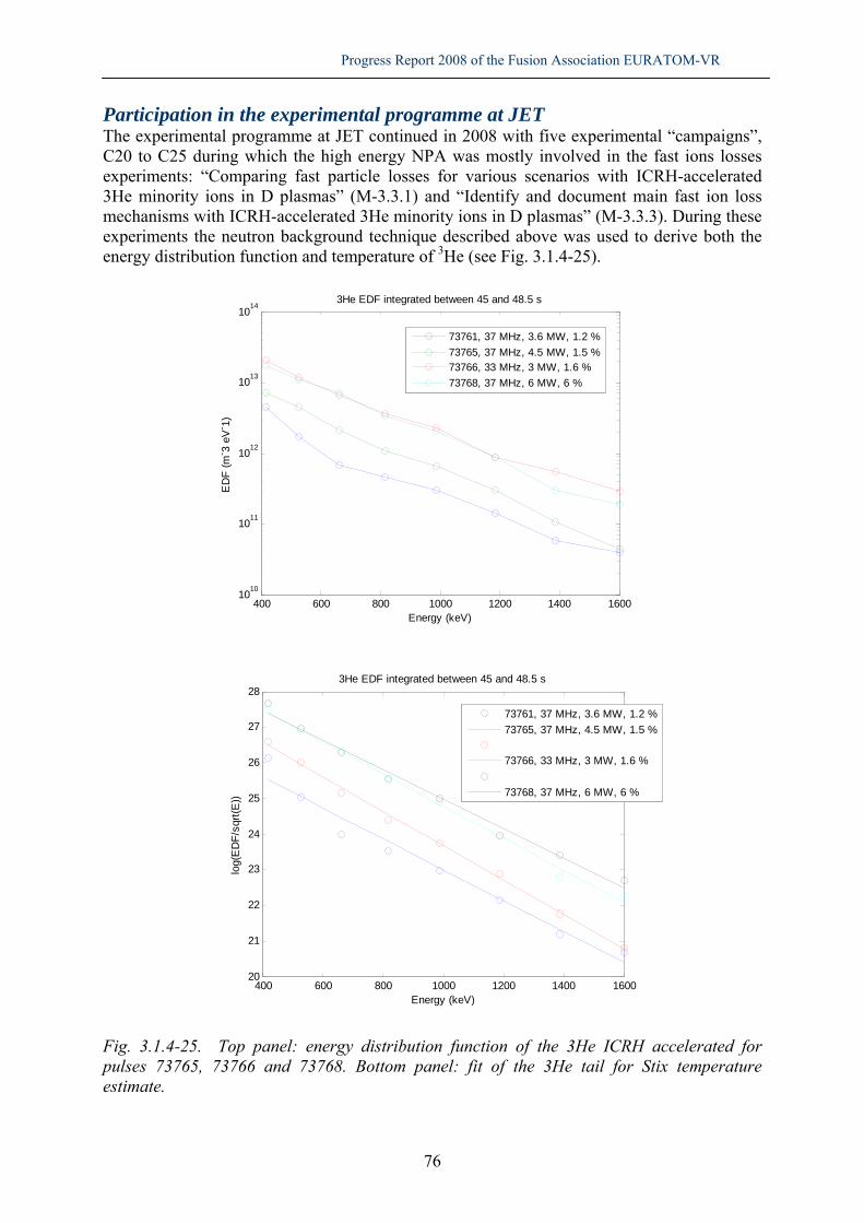
Progress Report 2008 of the Fusion Association EURATOM-VR
76
Participation in the experimental programme at JET The experimental programme at JET continued in 2008 with five experimental “campaigns”, C20 to C25 during which the high energy NPA was mostly involved in the fast ions losses experiments: “Comparing fast particle losses for various scenarios with ICRH-accelerated 3He minority ions in D plasmas” (M-3.3.1) and “Identify and document main fast ion loss mechanisms with ICRH-accelerated 3He minority ions in D plasmas” (M-3.3.3). During these experiments the neutron background technique described above was used to derive both the energy distribution function and temperature of 3He (see Fig. 3.1.4-25).
Fig. 3.1.4-25. Top panel: energy distribution function of the 3He ICRH accelerated for pulses 73765, 73766 and 73768. Bottom panel: fit of the 3He tail for Stix temperature estimate.
400 600 800 1000 1200 1400 16001010
1011
1012
1013
1014
Energy (keV)
ED
F (m
- 3 eV
- 1)
3He EDF integrated between 45 and 48.5 s
73761, 37 MHz, 3.6 MW, 1.2 %73765, 37 MHz, 4.5 MW, 1.5 %73766, 33 MHz, 3 MW, 1.6 %73768, 37 MHz, 6 MW, 6 %
400 600 800 1000 1200 1400 160020
21
22
23
24
25
26
27
28
Energy (keV)
log(
ED
F/sq
rt(E
))
3He EDF integrated between 45 and 48.5 s
73761, 37 MHz, 3.6 MW, 1.2 %73765, 37 MHz, 4.5 MW, 1.5 %
73766, 33 MHz, 3 MW, 1.6 %
73768, 37 MHz, 6 MW, 6 %

Progress Report 2008 of the Fusion Association EURATOM-VR
77
3.1.5 R&D for ITER Instrumentation for ITER: TPR development During 2008 the Thin-foil proton recoil (TPR) neutron spectrometer concept was investigated in more detail as a potential candidate for an ITER High Resolution Neutron Spectrometer. The spectrometer would consist of a thin polythene foil and an annular silicon detector upon which a collimated neutron beam falls (Fig. 3.1.5-26). Some protons will be knocked out of the foil by elastic n,p scattering. A fraction of these would fall on the segmented annular silicon detector. The energy of the protons is measured and can be related back to the energy of the incoming neutron. The thickness of the foil and the distance from the foil to the detector determines the efficiency and energy resolution of the system.
Fig. 3.1.5-26. Schematic for a TPR type detector. A study was performed to find the optimum foil thickness and distance between the components. The detector was assumed to be at the designated ITER location with a neutron flux consistent with a 350-MW plasma. A Monte Carlo simulation of the detector was used to determine the energy resolution and efficiency of each configuration. From that it is possible to determine how long the detector will need to operate to determine the ion temperature to the accuracy ITER requires (±10%). The results are indicated in Fig. 3.1.5-27 for a plasma of temperature 20 keV. ITER requires a 100ms sampling rate so these results indicate that an optimal TPR instrument would exceed that by a factor of 100.
Fig. 3.1.5-27 Contours indicate the time in milliseconds to measure a 20 keV ion temperature to 10% accuracy for many possible configurations of the TPR detector.

Progress Report 2008 of the Fusion Association EURATOM-VR
78
Contracts and Collaborations Contracts The work on neutron diagnostics has been supported by the Faculty of Science and Technology at Uppsala University, the Swedish Research Council and by a number of EFDA contracts. Some details on the EFDA contacts are given in Table 3.1.1-1 below. The work on JET’s neutral particle analyzers was part of a long-term secondment to JET for one member of the team (Marco Cecconello). This secondment ended Dec. 31, 2008. Table 3.1.1-1. Neutron-based contracts within the Work Program 2008-2009 of EFDA’s Topical Groups for Diagnostics (DIA) and Heating and Current Drive (H&CD), as well as within the cross-disciplinary grouping “TGS”. Contract number: EFDA WP08-09-
Title Baseline support (20%)
Priority support (40%)
Hardware support (40%)
VR resp. officer
TGS-01a-01 Neutron spectrometer for fast particle confinement
1.5 ppy 0.33 ppy 26 kEUR* Marco Cecconello, UU
DIA-01-05 Neutron Spectroscopy as Fuel ion diagn.
0.4 ppy Sean Conroy, UU
DIA-01-06 Neutron-based diagnostics
1.5 ppy 0.33 ppy Göran Ericsson, UU **
HCD-01-01 Analysis of ASDEX neutron spectra
0.3 ppy Göran Ericsson, UU
* UU share of a total 56 kEUR within the contract ** Task coordination Collaborations Below is a list of the persons involved in the collaborations that have been described in the diagnostic project areas above: • University Bicocca, Milano, Italy: G.Gorini, M.Tardocchi, M.Albergante, F.Ognissanto • ENEA-Frascati, Rome, Italy: B.Esposito, L.Petrizzi • IST University, Lisboa, Portugal: J.Sousa, A.Combo, N.Cruz and R.Costa Pereira • CSU-JET, UK: A.Murari, T.Johnson, J.Ongena, M.Laxåback, M.Tsalas • UKAEA-JET, UK: S.Popovichev, V.Kiptily, S.Sharapov, S.Pinches • UKAEA-MAST, UK: R.Akers, M.Turnianski, M.Walsh and the MAST team • Institute for Theoretical Physics, University of Innsbruck, Austria: V.Yavorskij • Risö National Lab., Denmark: Sören Korsholm • IPPLM, Poland: M.Schulz

Progress Report 2008 of the Fusion Association EURATOM-VR
79
Publications section 3.1 Ph.D. and Ph.Lic. thesis
1. H.Sjöstrand, Neutron Spectroscopy Instrumentation and Methods for Fusion Plasmas, PhD Thesis, Acta Universitas Upsaliensis, Digital Comprehensive Summaries of Uppsala Dissertations from the Faculty of Science and Technology 556, Uppsala 2008
2. C.Hellesen, Fast ion diagnostics in JET D plasmas using neutron emission spectroscopy, Licentiate Thesis, Uppsala University 2008
3. E.Andersson Sundén, Instrumentation and analysis methods for fusion neutron spectroscopy, Licentiate Thesis, Uppsala University 2008
Bachelor’s and Master’s theses Work on 3 Theses for Master of Science (H.Helberg, B,Molander, P.Kårén) was initiated during 2008. The work was concluded and will be reported in 2009.
4. L.Heijkenskjöld, Benchmarking of modeled TOFOR backscatter against neutron emission rate as measured by KN1, Bachelor’s Thesis, Uppsala University 2008
5. M.Skiba, A phenomenological model of beam target neutron emission spectra for fusion plasmas, Bachelor’s Thesis, Uppsala University 2008
Peer reviewed journals
6. H. Sjöstrand, et al., Triton burn up neutron emission in JET low current plasmas, J. of Physics D: Applied Physics 41 115208 10pp (2008)
7. M. Gatu Johnson et al,, The 2.5 MeV Neutron Time-of-Flight Spectrometer TOFOR for Experiments at JET, Nucl. Instr. Meth. A591 (2008) 417
8. Sean W. Conroy et al., Neutron spectrometer for ITER using silicon detectors, Rev. Sci. Instrum. 79 (2008) 10E508
9. C. Hellesen et al., Validating TRANSP simulations using neutron emission spectroscopy with dual sight lines, Rev. Sci. Instrum. 79 (2008) 10E510
10. F. Ognissanto et al (incl. S. Conroy), Line integration effects on ion temperatures in tokamak plasmas measured with neutron emission spectroscopy, Rev. Sci. Instrum. 79 (2008) 10E511
11. E. Ronchi et al., A neural networks framework for real-time unfolding of neutron spectroscopic data at JET, Rev. Sci. Instrum. 79 (2008) 10E513
12. L. Giacomelli et al., Neutron emission spectroscopy results for internal transport barrier and mode conversion ion cyclotron resonance heating experiments at JET, Rev. Sci. Instrum. 79 (2008) 10E514
International conferences:
13. S. Popovichev et al., (incl. S. Conroy, A. Hjalmarsson, G. Ericsson, M. Weiszflog), Neutron Emission Profile and Neutron Spectrum Measurements at JET: Status and Plan, Proc. of International work shop on Burning plasma diagnostics, Varenna, AIP Conference Proceedings 988 (2008) 275
14. G. Ericsson et al., Prospects for High Resolution Neutron Spectroscopy on High Power Fusion Devices in View of the Recent Diagnostic Developments at JET, Proc. of International conference on burning plasma diagnostics, Varenna, AIP Conference Proceedings 988 (2008) 307

Progress Report 2008 of the Fusion Association EURATOM-VR
80
15. M. Gatu Johnson et a., The TOFOR Neutron Spectrometer for High Performance Measurements of D Plasma Fuel Ion Properties, Proc. of International conference on burning plasma diagnostics, Varenna, AIP Conference Proceedings 988 (2008) 311.
16. E. Andersson Sundén et al., Evaluation of Spectral Unfolding for Neutron Spectroscopy, Proc. of International conference on burning plasma diagnostics, Varenna, AIP Conference Proceedings 988 (2008) 315
17. H. Sjöstrand et al., Fusion Power Measurements using a Combined Neutron Spectrometer- Camera system at ITER, Proc. of International work shop on Burning plasma diagnostics, Varenna, AIP Conference Proceedings 988 (2008) 319
18. E. Ronchi et al., Applications of Neural Networks for Free Unfolding of Experimental Data from Fusion Neutron Spectrometers, Proceedings of the 8th International FLINS Conference on Computer Intelligence in Decision and Control, Madrid, Spain, September 2008) IoP Preprint EFDA–JET–CP(08)06-01
19. J. Ongena et al., (incl. S. Conroy, G. Ericsson, C. Hellesen, A. Hjalmarsson), Heating Optimization Studies at JET in Support of ITER. Proceedings of the 22nd IAEA Fusion Energy Conference, Geneva, Switzerland, October 2008, IoP Preprint EFDA–JET–CP(08)05/21
20. M Cecconello et al, Study of advanced neutron diagnostics for MAST, 4th IAEA Technical Meeting on Spherical Tori, 14th International Workshop on ST, Rome, Italy, October, 7 – 10, 2008
21. M.Cecconello et al., Resistive tearing modes dynamics with plasma control in a reversed field pinch, Proceedings of the 35th EPS Conference on Plasma Phys. Hersonissos, Greece, 9 - 13 June 2008
22. L.Frassinetti et al. (incl. M.Cecconello), Active feedback control of QSH in EXTRAP-T2R, Proceedings of the 35th EPS Conference on Plasma Phys. Hersonissos, Greece, 9 - 13 June 2008
Contributions to ITPA meetings or TF meetings:
23. Preliminary 2.5-MeV neutron yield results using a neutron spectrometer-camera system, H.Sjöstrand and the Uppsala University neutron group, JET TF-D meeting December 18, 2008
24. Analysis of digital stored waveforms for neutron measurements, E.Andersson Sundén and the Uppsala University neutron group, JET TF-D meeting December 18, 2008
25. Neural Network Tomography for real-time unfolding of neutron emissivity profiles from KN3 at JET- First results, E.Ronchi and the Uppsala University neutron group, JET TF-D meeting November 27, 2008
26. Neutron Spectrometry Proposals of experiments for C26 and C27, G.Ericsson and the Uppsala University neutron group, JET TF-D meeting October 23, 2008
27. Analysis of the Neutron and gamma background on the high energy NPA, Marco Cecconello, JET TF-D meeting October 16, 2008
28. Investigation of ICRH physics in (3He)D plasmas with TOFOR, Marco Tardocchi and the Uppsala-Milano neutron groups, JET TF-M meeting June 17, 2008
29. Preliminary data analysis of NPA data for M-3.3.3, Marco Cecconello, JET TF-M meeting June 17, 2008
30. Validating TRANSP simulations using Neutron Emission Spectroscopy with Dual Sight lines, Carl Hellesen and the Uppsala University neutron group, JET TF-D meeting May 6, 2008
31. A Bipolar LED drive technique for high performance, stability and power in the nanosecond time scale, E.Ronchi and the Uppsala University neutron group, JET TF-D meeting April 3, 2008

Progress Report 2008 of the Fusion Association EURATOM-VR
81
32. Commissioning of TOFOR, C.Hellesen and the Uppsala University neutron group, JET TF-H meeting March 4, 2008
33. Benchmark the effect of the scattered neutrons on the total neutron flux as observed with TOFOR, Maria Gatu Johnson, Carl Hellesen and the Uppsala University neutron group, JET TF-D meeting February 28, 2008
34. Neutron spectrometers: TOFOR and MPRu (KM9, KM11), S. Conroy, G. Ericsson and the Uppsala University neutron group, Joint JET TF-D/TF-H Meeting, January 29 2008
35. Neutral particle analyzer (KF1, KR2), Marco Cecconello, Joint JET TF-D/TF-H Meeting, January 29 2008
36. Users' requirements from unfolding, S. Conroy, E. Andersson-Sundén, E. Ronchi, C. Hellesen, G. Ericsson, M. Gatu-Johnson, A. Hjalmarsson, H. Sjöstrand, M. Weiszflog, Technical meeting: Unfolding and Tomographic techniques for Fusion applications July 1-2 2008
37. Evaluation of unfolding techniques, E. Andersson-Sundén, S. Conroy, E. Ronchi, C. Hellesen, G. Ericsson, M. Gatu-Johnson, A. Hjalmarsson, H. Sjöstrand, M. Weiszflog, Technical meeting: Unfolding and Tomographic techniques for Fusion applications July 1-2 2008
38. A Neural network framework for unfolding neutron spectroscopic data at JET with real-time capabilities, E. Ronchi, S. Conroy, E. Andersson-Sundén, C. Hellesen, G. Ericsson, M. Gatu-Johnson, A. Hjalmarsson, H. Sjöstrand, M. Weiszflog, Technical meeting: Unfolding and Tomographic techniques for Fusion applications July 1-2 2008
39. Neutron emission spectroscopy as a tool for determining fusion plasma conditions, M.Gatu Johnson and the Uppsala University neutron group, Nordic Network for Women in Physics, Uppsala University, Sept. 19, 2008
40. ITER relevant developments in neutron diagnostics at UU, E.Andersson Sundén, M.Cecconello, S.Conroy, G.Ericsson, M.Gatu Johnson, C.Hellesen, E.Ronchi, H.Sjöstrand, M.Weiszflog, G. Gorini, M. Tardocchi, ITPA Diagnostics meeting, Ghandinagar, India, Nov.17-21 2008
3.2 Plasma Spectroscopy E Rachlew, S Menmuir (PhD student finished June 2008), G Vall-llosera (PhD student, finished June 2008), Y Ding (MSc student finished Jan 2009), S Ehlers (MSc finished June 2009)
Major collaborations and involvement in the EFDA Work Programme The group has contributed to the JET-EFDA work programme in all the campaigns. The group has had active international collaborations within the EFDA programme with the following;
• UKAEA-MAST project. • CEA-ToreSupra project. • FOM-TEXTOR group.

Progress Report 2008 of the Fusion Association EURATOM-VR
82
Main milestones • Modelling of the radiative power from the ToreSupra divertor using the Onion-Skin
Collisional Radiative model and the ADAS data structure.
• Observations and interpretations of the q-profile behavior with auxiliary heating systems at JET.
Scientific work The plasma spectroscopy programme is based at the Department of Physics, KTH, with the participation of both graduate and undergraduate students and research visitors. The research programme contains direct experiments at various fusion plasmas as well as basic experiments for achieving atomic and molecular data for input to the modeling of the radiation from the hot plasma. Modelling of radiation from fusion plasmas using ADAS The group is a member of the ADAS (Atomic Data Analysis Structure) consortium and contributes to the development of the modeling and analysis of spectroscopic observations from fusion plasmas. As input to the modeling codes basic atomic and molecular data is required which is obtained in gas phase experiments using synchrotron radiation for excitation of the molecules. Modelling the divertor radiation from the ToreSupra tokamak In a collaborative project with Y Corre, CEA and the group at KTH, the Onion Skin Collisional Radiative model (OSCR), previously applied at KTH for the radiation from the T2R experiment, have been developed for interpreting the radiation from the ToreSupra divertor plasma observed with the bolometer diagnostics. The results showed a good agreement with the observed data and the modeling using the ADAS data base for the carbon and oxygen radiation. Experiments at MAST The group has participated in the calibration and analysis of the first data from the new upgraded MSE multichannel diagnostic at the MAST spherical tokamak. The first data were presented by the MAST team at the international diagnostic conference. Experiments at JET EFDA The experiments have focused on the determination of the q-profile using the motional Stark spectroscopy system (MSE) at JET during the different campaigns at JET. The analysis includes EFIT equilibrium reconstructions with several different input constraints such as the pressure profiles, the toroidal velocity measured from charge exchange diagnostic, and the data from the Faraday diagnostics. Studies of the influence of ELMs on the MSE data have also been concluded and presented in publication. Spectroscopy R&D for ITER Within the ADAS consortium several groups collaborates for the spectroscopic diagnostic systems for ITER. During the year the group participated in the ADS meeting with discussions of further development of the data analysis systems.

Progress Report 2008 of the Fusion Association EURATOM-VR
83
Publications section 3.2 Refereed journals
1. F Romanelli, R Kamendje on behalf of JET-EFDA contributors incl E Rachlew: "Overview of JET results", International Atomic Energy Agency, IAEA, Geneve, 2008
2. M N A Beurskens, G Arnoux, A S Brezinsek et al incl E Rachlew: "Pedestal and ELM response to impurity seeding in JET advanced scenario plasmas", Nuclear Fusion 48, 095004 (2008)
3. Emilia R Solano, S Jachmich, F Villone, N Hawkes et al incl E Rachlew: "ELMs and strike point movements", Nuclear Fusion 48, 065005, 1-12 (2008).
4. Y Corre, E Joffrin, P Monier-Garbet et al incl. E Rachlew: "Hybrid H-mode scenario with nitrogen seeding and type III ELMs in JET", Plasma Phys. Control. Fusion 50, 115012 (2008).
5. K Rantamäki, A Ekedahl, M Goniche et al incl E Rachlew: "LH power coupling over ITER-like plasma-wall distances at JET", submitted, Plasma Phys. Control. Fusion, 2008.
6. H Bergsåker, S Menmuir, E Rachlew, P R Brunsell, L Frassinetti and J R Drake: “Metal impurity fluxes and plasma-surface interactions in EXTRAP T2R" J. Phys: conf. Series 100, 062030 (2008).
7. G Vall-llosera, M Coreno, P Erman, M A Huels, K Jakubowska, A Kivimäki, M Stankiewicz and E Rachlew: "VUV photoionisation of free azabenzenes: Pyridine, pyrazine, pyrimidine, pyridazine and s-triazine", Int. J. Mass Spectrometry 275, 55-63 (2008).
8. G Vall-llosera, B Gao, A Kivimäki, M Coreno, J Álvarez Ruiz, M de Simone, H Ågren and E Rachlew: "The C 1s and N 1s near edge x-ray absorption fine structure spectra for five azabenzenes in the gas phase", J Chem Phys. 128, 044316-1-12 (2008).
9. G Vall-llosera, M A Huels, M Coreno, A Kivimäki, K Jakubowska, M Stankiewicz and E Rachlew: "Photofragmentation of 2-deoxy-D-ribose molecules in the gas phase, Chem. Phys. Chem.9, 1020-1029 (2008).
Conference contributions
10. L Frassinetti, P R Brunsell, M Cecconello, J R Drake, M W M Khan, S Menmuir, K E J Olofsson:"Active feedback control of QSH in EXTRAP-T2R", Proceedings of the 35th EPS Conference on Plasma Physics (2008). P2-056
11. V Riccardo, P Beaumont, S Hacquin et al incl. E Rachlew: "Progress in understanding halo current at JET" Proceedings of the 22nd IAEA conference on fusion plasma physics, Geneva, Oct. 13- 18, 2008
12. K Krieger et al incl. S Menmuir:"Be wall sources and migration in L-mode discharges after Be evaporation in the JET tokamak" 18th PSI, Plasma surface interactions in controlled fusion plasmas, Toledo, Spain, 26-30 May, 2008
PhD thesis
13. Gemma Vall-llosera: Synchrotron radiation studies of gas phase molecules; from hydrogen to DNA sugars, March 2008
MSc thesis
14. Yuan Ding: Modelling of the radiative power loss from the plasma of the ToreSupra tokamak; Dec. 2008

Progress Report 2008 of the Fusion Association EURATOM-VR
84
15. Sandra Ehlers: “Temporal drifts of the magnetic field in superconductive undulators”, June 2009
3.3 Diagnostic activity at JET J. Brzozowski†, M. Cecconello Work with JET diagnostics during JOC secondments J. Brzozowski worked during January-March 2008 at EFDA-JET under a JET Operation Contract (JOC) with UKAEA where duties are divided between tasks as Session Leader and as Spectroscopy Diagnostician. Appointments include Deputy Task Force Leader for Diagnostics, Project Manager of one of the JET-EP2 Spectroscopy Enhancement Projects and Scientific Contact Person for the Swedish EURATOM Association with EFDA JET. The work as Session Leader includes participation in teaching and supervision of Trainee Session Leaders. The work as Deputy TFL includes participation in JPEC, JET Programme Execution Committee. M Cecconello worked during January-March 2008 and June-December 2008 at EFDA-JET under a JET Operation Contract (JOC) with UKAEA as Responsible Officer (RO) of Neutral Particle Analyzers (NPA), in support of the research activity and operation of JET. Duties as RO include diagnostic support and development, data analysis and modelling, code maintenance and development. Research activity is carried out in two areas: modelling of neutral fluxes at low energies (< 1 MeV) due to NBI heating, toroidal field ripples and Edge Localized Modes and fast ion production, confinement and losses (with energies up to 4 MeV) during ICRH.

Progress Report 2008 of the Fusion Association EURATOM-VR
85
4 Concept improvements and fundamental understanding 4.1 Development of the reversed-field pinch concept 4.1.1 Non-linear MHD dynamics L. Frassinetti, M. Cecconello, M.W.M. Khan (PhD student), P. Brunsell, J. R. Drake, In collaboration with: E. Rachlew, S. Menmuir (PhD student) Dept. of Physics, SCI, KTH The experimental discovery of a new RFP dynamo regime termed Quasi-Single Helicity (QSH) is a major break-through in RFP research. In the QSH regime, the toroidal field reversal is sustained dominantly by a single tearing mode. The QSH regime contrasts to the standard Multi-Helicity (MH) dynamo regime. In the MH regime, the toroidal field reversal is sustained through the non-linear interaction of several tearing modes, causing magnetic island overlap and a stochastic magnetic field in the plasma core. Magnetic topology of QSH regimes In the theoretically predicted single helicity (SH) regime the dynamo is produced by the interaction of a single tearing mode with the velocity field produced by an electrostatic drift due to a small charge separation. The SH plasma core is characterized by a magnetic island generated by a single mode and has no magnetic chaos. On the experimental side, regimes in which the dynamo is produced mainly by a single (dominant) mode, but in which other (secondary) modes have a small contribution have been obtained, and are referred to as quasi single helicity (QSH) regimes. In these regimes the plasma core is still characterized by a magnetic island, but part of the core becomes chaotic due to the presence of the secondary modes. Transitions to QSH regimes are characterized by the decrease of the secondary modes. As a result, the magnetic stochasticity in the core decreases, improving the confinement. Theoretical and experimental studies show that the core of QSH plasmas is characterized by the presence of a magnetic island. An important part of the project is to study the characteristics of the QSH island in EXTRAP T2R. The presence of the magnetic island is verified by studying the magnetic topology of the plasma core. The topology is determined from the equation of the magnetic field lines in flux coordinates, considering both the equilibrium field and the perturbations. In particular, a Hamiltonian numerical code for field line tracing was developed and applied to the experimental data of EXTRAP T2R to obtain a Poincaré map of the magnetic field. By using the code for the determination of the Poincaré map of magnetic field lines, the magnetic topology of MH and QSH regimes were compared. The EXTRAP T2R plasma core was confirmed to be stochastic in the MH regime, while a clear magnetic island was present in the QSH regime, see Figure 4.1-1. The size of the island was correlated with the mode amplitude. A clear positive scaling with the dominant mode was found, see Figure 4.1-2.

Progress Report 2008 of the Fusion Association EURATOM-VR
86
Electron heat transport in QSH regimes The conserved magnetic flux surfaces inside the magnetic island should be the origin of a strong local heat transport reduction, since the surrounding part of the core is characterized by a stochastic magnetic field. In principle, the QSH island should have better confinement properties than the standard MH regime. First, the heat diffusivity in the MH regime was determined by developing a 1D heat transport code to simulate the electron temperature profile. The effect of the magnetic island was taken into consideration in the second step, by considering the island as a perturbation of the MH profile. For this purpose, a perturbed heat equation was introduced in order to determine the temperature increment inside the island. The heat diffusivity was calculated by comparing simulated and experimental results.
Figure 4.1-1. Core magnetic topology in a QSH plasma.
Figure 4.1-.2. Correlation of the island width with the dominant mode amplitude.
In standard MH plasmas, the core electron heat diffusivity is 1000±500 m2/s. This value is consistent with those determined in other reversed field pinch devices. A clear reduction of the electron heat transport inside the QSH island is found. The application of the code to QSH plasmas shows that the island heat diffusivity is one to two order of magnitude lower, being in the range 10 – 200 m2/s. The corresponding temperature increment inside the island is approximately 10 – 50 eV. In Figure 4.1-3., an example of the temperature increment inside the magnetic island of EXTRAP T2R is shown. More detailed studies show that the island heat diffusivity is reduced at high plasma current. This result is shown in Figure 4.1-4.

Progress Report 2008 of the Fusion Association EURATOM-VR
87
Figure 4.1-3. Electron temperature increment inside the magnetic island.
Figure 4.1-4. Scaling of the island electron heat diffusivity with the plasma current.
Active generation of QSH regimes The QSH may in principle be a route to improvement of RFP confinement. However, the duration of spontaneous QSH is only 1% of the pulse duration in EXTRAP T2R. The active generation of QSH states by using the EXTRAP T2R feedback system is therefore an interesting possibility. The feedback system of EXTRAP T2R is utilized to apply an external resonant magnetic perturbation (RMP) to the plasma edge. The toroidal harmonic of the applied RMP corresponds to that of the m=1 tearing mode resonant closest to the minor axis.

Progress Report 2008 of the Fusion Association EURATOM-VR
88
Two strategies were tested to produce the RMP: the open loop operation and closed-loop operation. In the open loop, the active coils produce the RMP with the desired harmonic and no active control on the MHD modes is performed. In the closed-loop, the feedback tries to suppress all MHD modes excluding the one with the desired harmonic. Both the open-loop and the closed-loop operation significantly increase the number of QSH produced during the discharge. The role of the RMP amplitude was studied in detail. With sufficiently large RMP amplitudes, the QSH probability increases from 1% (spontaneous QSH) to nearly 10%. This is shown in Figure 4.1-5. The closed-loop operation allows the production of QSH islands with better characteristics. The induced QSHs are characterized by a magnetic island with a size larger than the spontaneous QSH island, as shown in Figure 4.1-6.
Figure 4.1-5. Percentage of the discharge characterized by QSH as a function of RMP amplitude.
Figure 4.1-6. Island width versus TM amplitudes.
Tearing mode dynamics with a resonant magnetic perturbation The behaviour of the internal tearing mode subject to an external RMP is interesting. The control coils at EXTRAP T2R are used to apply an external RMP at the plasma edge. The response of the tearing mode corresponding to the same harmonic as the RMP is studied. The attention is focused on the mode dynamics: the time evolution of the mode amplitude and mode velocity. The tearing mode dynamics is clearly affected by the RMP. The corresponding amplitude and velocity have a characteristic behaviour that is dependent on the RMP amplitude. An example is shown in Figure 4.1-7.

Progress Report 2008 of the Fusion Association EURATOM-VR
89
Figure 4.1-7. (a) TM amplitude
(b) TM velocity. External RMP amplitude is 0.2mT (red) and 0.4mT (blue).
Publications section 4.1 Peer reviewed journals 1. Lorenzo Frassinetti, Alberto Alfier, Roberto Pasqualotto, Federica Bonomo, Paolo
Innocente, "Heat diffusivity model and temperature simulations in RFX-mod", Nuclear Fusion, vol. 48 pp. 045007, 2008
2. Kiyoyuki Yambe, Lorenzo Frassinetti, Satoru Kiyama, Yoichi Hirano, Haruhisa Koguchi, Hajime Sakakita, "Frequency Dependence of Fast Magnetic Fluctuations in TPE-RX Reversed-Field Pinch Plasma", Plasma and Fusion Research, vol. 3 pp. 60, 2008
3. Alberto Alfier, Roberto Pasqualotto, Gianluca Spizzo, Alessandra Canton, Alessandro Fassina, Lorenzo Frassinetti, "Electron temperature profiles in RFX-mod", Plasma Physics and Controlled Fusion, vol. 50 pp. 035013, 2008
Conference contributions with proceedings 4. Marco Cecconello, Lorenzo Frassinetti, K Erik J Olofsson, M Waqas M Khan, Per R
Brunsell, "Resistive tearing modes dynamics with plasma control in a reversed field pinch", 35th EPS Conf on Plasma Physics, Hersonissos, 9-13 June 2008, ECA Vol. 32D, P-1.1071 (2008), 2008
5. Lorenzo Frassinetti, Per R. Brunsell, Marco Cecconello, James R. Drake, M. Waqas M. Khan, Sheena Menmuir, K. Erik J. Olofsson, "Active feedback control of QSH in EXTRAP-T2R", Proc. 35th EPS Conf. on Plasma Phys., Hersonissos, 9-13 June 2008, ECA, pp. P2.056, 2008

Progress Report 2008 of the Fusion Association EURATOM-VR
90
4.1.2 Computational methods with applications to the RFP J. Scheffel, A. Mirza (PhD student) In collaboration with: D.D. Schnack, Univ. Wisconsin-Madison, USA Theoretical and numerical understanding of RFP confinement Theoretical and numerical models for reversed-field pinch confinement modelling need further refinement. Because of the complexity of the strongly nonlinear MHD phenomena and the strongly separated Alfvén and resistive time scales, relatively limited physical effects have so far been included in the numerical computations. As a result, we have not yet been able to reach reliable results on the operational limits of confinement in the RFP. The fusion potential of the RFP certainly is of significant interest, since an RFP reactor could feature high plasma beta (resulting in compact physical dimensions), using little or no beam or radio frequency heating and using normal magnetic coils, resulting in low capital costs and low cost of produced electricity. Our numerical simulations of RFP plasmas in the advanced regime, where current driven tearing modes were eliminated by current profile control, have provided favourable scalings of on-axis temperature (T (0) ∝ (I 2 / N )0.74 ) and poloidal beta (βθ ∝ (I 2 / N )−0.12 ). To better understand and possibly find modifying effects to the limited energy confinement scaling (τ E ∝ (I 2 / N )0.50 ), improved modelling is required. The causes for the development to quasi-single helicity states with a superimposed strong m = 0 mode, the role of pressure driven instabilities and the possible stabilising mechanisms from two-fluid and kinetic effects are all addressed in this study. In the project, we extend our earlier work to more precise numerical studies of the effect of pressure driven modes in the high beta scenarios. It has been claimed that resistive-g modes may be eliminated by inclusion of heat conduction in the energy equation. We test this conjecture, carried out in traditional delta-prime theory, by developing a GWRM (see below) code, that solves the resistive MHD equations in the entire plasma domain. In particular, it is essential to determine the effect at higher, reactor relevant beta values. Studies of two-fluid effects, in particular the Hall and diamagnetic contributions to Ohm’s law, will be included. The effect of Larmor radius on the resistive g-modes in the RFP will be subsequently addressed using the Vlasov-fluid model. The Generalized weighted residual method (GWRM) During recent years, new computational tools have been developed within this project. Employing generalized spectral residual methods, solutions to the initial-value partial differential equations are determined as finite, approximate Chebyshev polynomial expansions. The solutions, being semi-analytical in form, represent not only space but also time and physical parameters explicitly. Time stepping is avoided completely. This eliminates numerical stability restrictions on the time domain and problems with vastly separated time scales can thus be efficiently solved, as shown in this application. The efficiency of the Generalized weighted residual method (GWRM) will be further addressed, in particular through an optimized use of subdomains. The project thus combines two vital areas of research in fusion plasma physics and computational physics.

Progress Report 2008 of the Fusion Association EURATOM-VR
91
A number of benchmarking tests of the GWRM has been carried out. For a set of pde’s with wavelike solutions on two separated time scales, the solution traces the slower dynamics using less computational time than both the explicit Lax-Wendroff scheme and the implicit Crank-Nicholson scheme. We have further shown that the GWRM provides accurate solution of the nonlinear Burger equation, which features shock-like structure for weak dissipation, using only a few Chebyshev terms. Also the temporal solution of the linearized, Fourier-decomposed, resistive and compressible MHD equations for a cylinder has been computed, confirming the applicability of the GWRM to systems of MHD equations. As a spin-off result, a globally convergent and highly efficient root solver for systems of nonlinear algebraic equations has been developed. The Semi-implicit root solver (SIR) is shown to be efficient, robust and simple in comparison with the standard Newton method using linesearch and completely avoids landing on spurious roots. Publications Peer reviewed journals J. Scheffel and C. Håkansson, Solution of Systems of Non-linear Equations – a Semi-implicit Approach, accepted for publication in Appl. Numer. Math. Conference contributions with proceedings J. Scheffel and A. Mirza, Pressure driven resistive modes in the advanced RFP, 35th EPS Conference on Plasma Physics, Hersonissos, Crete, Greece 9-13 June, 2008.

Progress Report 2008 of the Fusion Association EURATOM-VR
92
5 Emerging technology 5.1 High purity ODS-tungsten materials
M. Muhammed, S. Wahlberg
Tungsten as a first wall material in a reactor. Develop method for fabrication of highpurity ODS-tungsten based materials
Main objectives The objective of the program is the fabrication of new tungsten alloys, optimized for use as plasma facing materials in a fusion energy reactor. ODS materials are considered, i.e. tungsten alloys containing highly dispersed lanthanum or yttrium oxide (La2O3 or Y2O3). Characterise powder precursors. Produce surface-coated stainless steel. Characterise samples. Status A novel method for the fabrication of high purity precursors for W-La-composite materials is under development. The precursor, as oxides, has shown to have the exact chemical composition required and with high homogeneity. The precursors were processed through reduction in hydrogen atmosphere to produce W-La2O3 nanostructured powders and sintered by spark plasma sintering (SPS) to a W-ODS alloy. Detailed physical and chemical characterisation and electron microscopic study of the microstructure has been undertaken. The group is participating in FEMaS-CA (Fusion Energy Materials Science – Coordination Action), a 36 months project starting the 1st October 2008. 5.2 Material and chemical problems due to corrosion H-P Hermansson Studies on problems regarding corrosion in the cooling system of ITER. Main objectives The knowledge of potential corrosion attacks within the cooling system of ITER and potential fusion power plants needs to be increased. Status Corrosion experiments on materials exposed during repeated drying cycles have been performed. Simulated operational periods with water and drying procedures with nitrogen gas have been simulated. The examination and evaluation of the test materials have just started. In addition, a literature review of the experience of using other gases than nitrogen for drying will be performed.

Progress Report 2008 of the Fusion Association EURATOM-VR
93
5.3 Waste recycling S. Nordlinder Techniques for waste recycle Main objectives The main objectives for 2008 is to investigate techniques for waste recycle Status Work in this area has been terminated in order to focus on the other areas in the technology programme. 5.4 Code development L. Spontón Maintain and develop the codes for in-vessel/ex-vessel safety issues Main objectives The main objectives for 2008 are to further develop the code to fulfil additional sequences specified in SADL for future safety assessment in the licensing procedure, including quality assurance of the INTRA code. Status The ongoing work includes code maintenance of the code INTRA and further development to include additional processes of importance regarding scenarios according to SADL. This will mean to include further models for processes of importance. Some initial studies using three dimensional modelling (CFD) for safety related issues have been initiated.

Progress Report 2008 of the Fusion Association EURATOM-VR
94
6 EFDA JET The Swedish Association is very heavily involved in the JET activity. Aspects of the scientific programme that support JET have been included in the various sections of this Annual Report. Here the participation in EFDA JET Orders and the JET Campaigns C20-C25 are summarized in table form. 6.1 EFDA JET Orders. Involvement of the RU in the EFDA JET Orders is summarized in Table 6.1.
Table 6.1 Swedish participation in JET Orders.
Task agreement Order Title ResponsibleJW6-TA-EP2-EDP (Enhancement)
JW6-OEP-VR-26 Erosion deposition diagnostics for ITER-like wall project
KTH M. Rubel
JW6-TA-EP2-SIW03 (Enhancement)
JW6-OEP-VR-21 JW7-OEP-VR-28 JW8-OEP-VR-30
Spectroscopy in support of ITER-like wall project
KTH T. Elevant
JW8-TA-EXP-04 (S/T Orders Camp)
JW8-O-VR-29
JET Campaigns C20-C25
6.2 EFDA JET Enhancements. Erosion deposition diagnostics for ITER-like wall project M. Rubel Study of material migration, i.e. local and global erosion and deposition processes, is a very important element of the JET programme. A set of various monitors, the so-called wall probes, have been developed and installed in JET. These are: (i) wall inserts in the inner wall cladding, (ii) deposition monitors and louver clips in the divertor, (iii) quartz micro-balance devices, (iv) rotated collectors and (v) cassettes with mirrors located. Items (iv) and (v) are located both on the main chamber wall and in the divertor: inner and outer leg and under the load bearing plate. Fig. 6.2.1 shows schematically the location of diagnostics in the vessel, whereas Fig. 6.2.2 (a) and (b) shows different diagnostic tools in the divertor and on a bracket for installation on the main chamber wall. The issue of material migration will be in focus during the JET operation with a full metal wall: ITER-Like Wall Project, as described in Paragraph 2.3.1. Therefore, a similar set of probes has been procured. In addition to those monitors, marker tiles have been designed in order to determine beryllium and tungsten migration and fuel inventory. VR is responsible for the procurement of mirrors and louver clips and for the coordination of the entire programme related to the wall probes.

Progress Report 2008 of the Fusion Association EURATOM-VR
95
Fig. 6.2-1. Location of diagnostics in JET: (a) schematic view, (b) detailed location in divertor.
diagnostic
Load bearing plate (divertor base) with diagnostics
Outer divertor carrier
Diagnostic
Rotating collector
QMB
Cassette with mirrors
shutter
cassette
holder
rotatable collector
Bracket assembly for installation of mirrors and deposition monitors
on the main chamber wall.
Fig. 6.2-2 (a) Different diagnostic tools in the divertor; (b) wall bracket with a cassette with mirrors and a rotating collector.

Progress Report 2008 of the Fusion Association EURATOM-VR
96
Spectroscopy in support of ITER-like wall project (SIW) T. Elevant, J. Brzozowski† and J.R. Drake The SIW project is part of a package of diagnostic enhancements which is to be implemented and used at JET during operation with an ITER-like wall during Framework Programme 7. The primary material choices for ITER is a full beryllium main wall with CFC (carbon fibre composite) at the strike points together with tungsten at divertor baffles and dome. Since this combination has not been tested in a tokamak previously, the ITER-like Wall project has been launched at JET implying replacement of the present first wall by an ITER-like wall followed by tests and operation with an adequate set of diagnostics. Presently, the JET wall and divertor consist of CFC, while the RF and LH antennas consist of Be and Cu coated stainless steel, respectively, with CFC protection tiles. Small amounts of Be are introduced by evaporation, and noble gases are frequently injected for transport studies (4He, Ne, Ar), or as minority species for RF-Heating (3He). The reference species for low Z elements for core and edge emission is C. The reference species for medium Z species in the VUV, XUV and X-ray region is Ni (an estimate of the Ni concentration is routinely performed using a high resolution X-ray crystal spectrometer). Installation of the ITER-like wall and a new divertor on JET will result in qualitatively different spectroscopic needs and technical challenges. The metal surfaces can be subjected to large power density and thus high erosion rates. In case the full W divertor option is selected, it is conceivable that C levels will be so low that Be has to act as the reference species for low Z elements, while it will be necessary to quantify the degree to which C is reduced. Spectra from W are very rich, and may result in blending with spectral lines from other elements in all wavelength ranges. The spectral line best suited to study W erosion is the one at 401 nm because modelled and experimental results are available to convert photon fluxes into erosion rates. However at this wavelength transmission losses by optical fibres are high, quantum efficiency of detectors is low and absolute calibration more difficult than for the spectral lines that best characterise C. For Be, spectral lines in the normal visible wavelength range exist, but many other suitable lines are in the blue as well. It will also be necessary to quantify the amount of Be released from W surfaces, the amount of W released from Be surfaces, and later in the experimental campaigns the release of Be and W from Be/W alloys once these have formed on the various surfaces. Both elements, and their alloys, are prone to melting; therefore specific spectral lines from several locations need to be provided in real time for possible use in machine protection. Core concentrations of Be and W and their relationship with erosion rates need to be studied in detail to allow a meaningful prediction of the same wall mix on ITER which is presently foreseen to be W/Be/C. To meet the new demands a number of spectroscopic diagnostic systems are modified and enhanced. All instrumentation that is not installed in the torus hall will be located in a dedicated laboratory (“spectrometer room”) in J1D, with a number of optical fibres routed from the various locations around the torus. Fibre patch panels in the spectrometer room will make the instrumentation interchangeable between different lines of sight should such need arise. The core emission from W is spread from the VUV (10nm-13nm) and XUV (4nm-7nm) to the Xray (0.1nm-0.4nm), with each spectral region being representative of a different part of the plasma, depending on the degree of ionisation and hence electron temperature. This

Progress Report 2008 of the Fusion Association EURATOM-VR
97
motivates the enhancements to the diagnostics KT4, KT7 and KX1 to complement the information from KT2 and KS6, which are not being modified since they are already adequate. The diagnosis of wall sources is a multi-dimensional task: high time resolution, good spatial resolution, large spectral coverage with good spectral resolution cannot be achieved simultaneously by a single instrument. The enhancements to KL1, KT1 and KT3 address the need for spatial coverage and resolution for spectral lines characteristic of Be, C, and W with slow time resolution. The enhancements to KS3 and KS8 provide partly wide spectral coverage for more detailed physics studies of erosion processes and partly ELM resolved time resolution, in specific locations on the inner wall and in the divertor. The responsibilities of VR are dealt with by the Fusion Division at KTH. This includes technical specifications, purchasing, installation, calibration, commissioning and tests of:
• 24 units of Polychromator Assemblies for PM Tubes (Art. 7 contract) • Mounts, tables, optical components, fibres, fibre connectors and patch panels in the
spectrometer room • Production, acquisition and analysis of KT1 data.

Progress Report 2008 of the Fusion Association EURATOM-VR
98
6.3 JET campaign participation C20-C25 Involvement of the RU in the EFDA JET Experimental Campaigns C20-C25 (EFDA JET Order EFDA CSU- JW8-O-VR-29 is summarized in Table 6.2.
Table 6.2 Swedish RU involvement in EFDA JET Campaigns C20-C25
Topic area in VR Work Programme Persons seconded to JET ISAF (days)
Transport J. Weiland, H. Nordman 68 Plasma wall interaction M. Rubel 72 Heating and current drive T. Hellsten, T. Johnsson 94 Diagnostics Neutron diagnostics G. Ericsson, S. Conroy, M Gatu
Johnson, H. Sjöstrand, M. Weiszflog, C. Hellesen, E. Ronchi, EAndersson Sunden
338
Diagnostics Spectroscopy diagnostics E. Rachlew, C. Jupén, J. Brzozowski
197
TOTAL 769 Involvement of the RU in the EFDA JET Experimental Campaigns C20-C25, EFDA JET (Notification JW8-N-VR-27) is summarized in Table 6.3.
Table 6.3 Swedish RU notifications in connection with EFDA JET Campaigns C20-C25
Topic area in VR Work Programme
Persons involved in notification activity Notification (ppy)
Energy and particle confinement/transport
A. Eriksson, J. Weiland, H. Nordman 0.22
Plasma wall interaction M. Rubel, P. Sundelin 0.21 Heating and current drive T. Hellsten, T. Johnson 0.35 Neutron diagnostics G. Ericsson, S. Conroy, E. Andersson Sunden,
M. Cecconello, M. Gatu Johnson, C. Hellesen, H. Sjöstrand, E. Ronchi, M. Weiszflog
0.36
TOTAL 1.14 Furthermore it can be pointed out that VR provided personnel to EFDA JET activity through secondments (Art 9.4 contracts) as follows: Seconded to the Operator on JOC contracts: • Operations and Core Spectroscopy Groups (J. Brzozowski). • Modelling Group (T. Johnson). • Diagnostics (M. Cecconello)

Progress Report 2008 of the Fusion Association EURATOM-VR
99
Close support unit: • Responsible Officer M. Laxåback. • Responsible Officer E. Asp.
VR also provided personnel as Session Leader, Scientific Coordinators, Diagnostic Coordinators and Control Room Experts in neutron diagnostics, spectroscopy and other diagnostics, as well as in plasma theory and modelling. 6.4 Fusion Technology at JET Involvement of the RU in the Fusion Technology at JET is summarized in Table 6.3.
Table 6.4 Swedish RU involvement in Fusion Technology at JET
Task Agreement / Fusion Technology Topic
Description Responsible Person
JW8-FT-JET Plasma facing components 3.39
First mirror tests M.Rubel
JW8-FT-JET Plasma facing components 3.40
Microanalysis of plasma deposited layers
H. Bergsåker

Progress Report 2008 of the Fusion Association EURATOM-VR
100
7 EFDA Task Forces and Topical Groups During 2008 there are two EFDA Task Forces with specified activity in the Work Programme: Task Force Integrated Tokamak Modelling (TF-ITM) and EFDA Task Force Plasma Wall Interaction (TF-PWI). VR is active in both of these Task forces. In particular, The TF Leader for TF-ITM is Pär Strand and the Deputy Task Leader for ICRH Heating, Current Drive and Fast Particles is Torbjörn Hellsten.
7.1 Task Force Integrated Tokamak Modelling Table 7.1 gives an overview of the activity in the Task Force Integrated Tokamak Modelling:
Table 7.1 Swedish RU involvement in the EFDA Task Force Integrated Tokamak Modelling
Activity Description Commitment (in ppy)
WP08-ITM-TFL1 Task Force Leader
Pär Strand 0.75 (eligible for preferential support)
WP08-ITM-TFL1 Deputy TF Leader IMP5 Heating, CD and Fast Particles
Torbjörn Hellsten 0.25 (eligible for preferential support)
ITM-08-IMP3 Transport code and discharge evolution
T2 standardized interfaces T3 use and comparison
0.08 0.13
ITM-05-IMP5 Heating, current drive and fast particles
T1 verification heat deposition T4 calc fast wave current drive
0.05 0.05
ITM-08-IMP5 Heating, current drive and fast particles
T1 coupling fast ion T3 fast ICRH code
0.15 0.33
WP08-ITM-TFL2 Tasks formed under TF Leadership
T3.2 density control pellet T3.3 impurity control
0.05 0.05
TOTAL 1.89 Of which 1.0 ppy
pref sup

Progress Report 2008 of the Fusion Association EURATOM-VR
101
7.2 Task Force Plasma Wall, Interaction Table 7.2 gives an overview of the activity in the EFDA Task Force Plasma Wall Interaction:
Table 7.2 Swedish RU involvement in Task Force Plasma Wall Interaction
Activity Description Commitment (in ppy)
WP08-PWI-01 PWI-08-TA-01/VR/BS/01
Post mortem analysis 0.58
WP08-PWI-01 PWI-08-TA-01/VR/PS/01
Post mortem analysis 0.2 (eligible for preferential support)
WP08-PWI-01 PWI-08-TA-01/VR/PS/01
Post mortem analysis hardware
10 kEuro eligible for preferential support)
WP08-PWI-03 PWI-08-TA-03/VR/BS/01
Analysis co-deposited layers 0.42
WP08-PWI-03 PWI-08-TA-03/VR/PS/01
Analysis co-deposited layers 0.1 (eligible for preferential support)
WP08-PWI-03 PWI-08-TA-03/VR/PS/01
Analysis co-deposited layers hardware
10kEuro (eligible for preferential support)
WP08-PWI-04 PWI-08-TA-04/VR/BS/01
Measurement, dust collection 0.42
WP08-PWI-04 PWI-08-TA-04/VR/PS/01
Measurement of dust TEXTOR 0.15 (eligible for preferential support)
WP08-PWI-06 PWI-08-TA-06/VR/BS/01
Transport and deposition, tracer experiments PFCs TEXTOR
1.0
WP08-PWI-06 PWI-08-TA-06/VR/PS/01
Transport and deposition, tracer 0.15
WP08-PWI-06 PWI-08-TA-06/VR/PS/01
Transport and deposition, tracer hardware
20kEuro (eligible for preferential support)
WP08-PWI-07 PWI-08-TA-07/VR/BS/01
High Z materials W test limiter 0.25
WP08-PWI-07 PWI-08-TA-07/VR/PS/01
High Z materials Mo mirrors 0.1 (eligible for preferential support)
WP08-PWI-07 PWI-08-TA-07/VR/PS/01
High Z materials Mo mirrors hardware
10kEuro (eligible for preferential support)
WP08-PWI-08 PWI-08-TA-08/VR/BS/01
ITER material mix post mortem mixed
0.42
WP08-PWI-08 PWI-08-TA-08/VR/PS/01
ITER material mix post mortem mixed
0.2 (eligible for preferential support)
TOTAL 3.9 ppy basic sup Of which 0.9 ppy pref sup 50 kEuro hardware pref sup

Progress Report 2008 of the Fusion Association EURATOM-VR
102
7.3 Topical Groups: Fusion Materials and Diagnostics During 2008 the EFDA Topical Groups have established work programmes. The Topical Groups are as follows: • Materials • Diagnostics • Heating and Current Drive • MHD • Transport
Table 7.3 gives an overview of the preliminary plans for activity in the Topical Group Materials based on the draft of the work programme as of 9 July, 2008:
Table 7.3 Swedish RU involvement in the EFDA Topical Group Fusion Materials (FM)
Activity Description Commitment (in pp)
Task Agreement Tungsten and Tungsten Alloys Development WP08-09-MAT-WWALLOY
Activity 2 Protection materials development. High purity and nano-structured W ODS alloys 2008
1.68
Table 7.4 gives an overview of the response to the first call for participation for activity in the Topical Groups Heating and Current Drive, MHD, Transport and Diagnostics based on the work programme as of 13 June, 2008:
Table 7.4 Swedish RU proposed involvement in the EFDA Topical Groups Diagnostics (DIA), Diagnostics for Physics Studies (TGS), and Heating & Current Drive (HCD) in response to first call 13 June, 2008.
Activity Description Commitment (in ppy)
Neutron based diagnostics WP08-DIA-01-06
Feasibility of a neutron spectrometer on ITER
0.5
WP08-TGS-01-06 Measurment conf alpha particles
Neutron spec for fast part studies 0.5
WP08-DIA-01-05 Fuel ion ratio
Feasibility broad band neutron spec as fuel diagnostic
0.2
WP08-HCD-01-01 Exper sim non-linear burning plasma plasma dynamics advanced scenarios
Neutron spec simulation non-linear dynamics
0.1
TOTAL 2008 1.3

Progress Report 2008 of the Fusion Association EURATOM-VR
103
7.4 Goal Oriented Training (GOTiT). Table 10.1 gives an overview of VR participation in Goal Oriented Training in Theory as included in definitive version of task agreement, 14 July, 2008.
Table 7.5 Swedish RU involvement in the GOTiT for 2008 and 2009 (start 1 October, 2008).
Activity Description Commitment (in ppy)
WP08-GOT-GOTiT Goal oriented training in theory
3.1.1.2 MHD, waves fast particles - ICRH
0.4 (mentoring) 2.0 (trainees)
TOTAL 2008 & 2009 2.4

Progress Report 2008 of the Fusion Association EURATOM-VR
104
8 ITPA 8.1 Overview of ITPA activities.
The International Tokamak Physics Activity (ITPA) provides a framework for internationally coordinated fusion research activities. The ITPA continues the tokamak physics R&D activities that have been conducted on an international level for many years resulting in the achievement of a broad physics basis essential for the ITER design and useful for all fusion programs and for progress toward fusion energy generally.
The ITPA has been operating under the auspices of the IAEA International Fusion Research Council since its inception in July 2001. The ITPA from February 25, 2008 now operates under the auspices of ITER in order to provide the framework for coordinated physics research activities proposed by the ITER-IO. These co-ordinated physics research activities will help develop the physics basis for ITER operation, integrate the expertise of the international fusion community into ITER, provide a pathway to exploit the capabilities of existing fusion facilities and programmes in support of ITER, and integrate results of the fusion programmes of the ITER Members into planning of ITER operation.
The Swedish Research Unit has participated in the following ITPA Topical Groups:
• Transport and Confinement
• Scrape Off Layer and Divertor
• Energetic Particle Physics
• Integrated Operational Scenarios
• Diagnostics
The ITPA will provide support to ITER in the fulfilment of its mission by helping to create a common international research programme organized around scientific issues and will facilitate the participation of the ITER Members in the ITER scientific programme. The integration of fusion researchers from the ITER Members into the ITER physics research programme will help ITER become a world-class scientific research facility for the benefit of the international fusion community.
Transport and Confinement Participation in Confinement, Modelling and Database topical groups and presentations at the Oak Ridge ITPA meeting where results on momentum transport were presented. Scrape Off Layer and Divertor The activity is concerned with material migration, fuel retention and fuel removal, dust production and development of in-situ diagnostics for erosion and deposition studies. In 2008 there were several presentations at two meetings in Avila, Spain and Fukuoka, Japan; see the list in 2.3.1.
Diagnostics First Mirror Test at JET for ITER is regularly reported at the ITPA meeting on diagnostics. The development of erosion and deposition diagnostic tools is also shown at these meetings.

Progress Report 2008 of the Fusion Association EURATOM-VR
105
9 Collaborative actions 9.1 Overview of collaborative actions. There is a very high level of collaboration between the research groups of the RU and other Associations as well as with EFDA JET. Furthermore there is a high level of participation in the EFDA Task Force for Integrated Tokamak Modelling and the Task Force for Plasma Wall Interaction. The groups also participate in ITPA and IEA activities.
Table 9.1 Overview of Collaboration activity with other Associations Topic Group Collaboration
Associates Comments
Energy and particle confinement /transport
Weiland (CTH) JET, ITER, Groups of Associations, CEA, CIEMAT, IPP
JET, TF ITM related ITPA activity
Fülöp (CTH) IPP, HAS, GA (USA) TF-TGS related Pavlenko (UU) Hellenic Rep. TG T related Strand (CTH) Groups of
Associations TF ITM related ITPA activity
MHD stability and plasma control
Brunsell (KTH)
ENEA, IPP TG-MHD related
Wahlberg (UU)
CRPP TG MHD related
Plasma wall interaction
Rubel (KTH) JET, Groups of Associations, FZJ, UKAEA
TF PWI related JET FT ITPA activity IEA IA on Fusion Reactor Nuclear Tech.
Heating and current drive
Hellsten (KTH) JET, ITER, CEA, TEKES, Conf Suisse
JET TF ITM related ITPA activity
Energetic particles Lisak (CTH) UKAEA TG-TGS Fülöp (CTH) UKAEA, HAS, IPP TG-TGS Theory and modelling for ITER
Strand (CTH) Groups of Associations
TF ITM related
Diagnostics Ericsson (UU) JET, ITER, ENEA, IST, UKAEA, MAST
JET , TG D related ITPA activity
Rachlew (KTH)
JET, IPP, UKAEA, CEA, MEdC
JET
Fülöp (CTH) HAS Optimization of operational regimes for improved concepts
Brunsell (KTH)
ENEA RFX, USA, Japan (IEA implementing agreement)

Progress Report 2008 of the Fusion Association EURATOM-VR
106
10 Technology 10.1 Art. 5.1b actions. The association has carried out work on the following EFDA Technology Art 5.1b Contracts during 2008. EFDA/06-1387 Low Oxygen Powder HIP (S. Wikman): Concluded 2008.
EFDA/06-1497 3-D cal ion losses (T. Johnson): Concluded 2008.
EFDA/07-1539 ITER ref scenarios (L. Sponton): Concluded 2008.
EFDA/07-1712 Annex 1 Effects of copper impurities (A. Molander): Concluded.
EFDA07-1712 Annex 2 Resistive wall modes (Y. Liu): Final report submitted.
EFDA/06-1437 Diag design for ITER (G. Ericsson): Final report submitted.
EFDA/06-1527 Manufacture of Be coatings (M. Rubel): Running:

Progress Report 2008 of the Fusion Association EURATOM-VR
107
11 Other activities 11.1 Training and education PhD training The physics programme of the Swedish Fusion Research Unit is university based. There are PhD programmes at CTH, KTH and UU. The research carried out by the students is fully integrated into the Work Programme of the Research Unit. On the average there are about 3 to 4 PhD examinations per year. This is slightly less than in previous years, due to a decrease in funding for PhD students. However there is no difficulty in recruiting students when funding is available. Masters programmes
• In addition to the PhD programme the three universities have Master of Science programmes where students can select fusion plasma physics topics for their thesis work. Annually there are about 15 MSc thesis students.
• Courses for the fourth year of engineering physics students and Erasmus Mundus Master students have been developed and given during the year.
Special
• Several projects for high school students have been developed and finished during the year.
• Jan Weiland was a member of the EPS prize jury for best PhD thesis 2008 and wrote the citation for Ivo Classen.
11.2 Public information The Swedish Public Information Group (PIG) officer within EFDA is Jan Scheffel at the Alfvén Laboratory in Stockholm. The Swedish PIG activities are mainly carried out in the form of lobbying, concentrated towards contact with government, parliament and energy administrators with the intention of strengthening fusion funding. The national funding for fusion is unchanged since the early 1990’s, and the situation is quite difficult with regards to retaining competence and enrolling younger scientists. The Swedish Energy Authority has a mission to consider fusion but has sofar not supported fusion research. A minor breakthrough came in 2008 when two fusion projects received certain support as “energy related basic research”. Apart from Euratom,

Progress Report 2008 of the Fusion Association EURATOM-VR
108
Swedish fusion research is funded by university faculties and by the Swedish Research Council (as basic research, in competition with several other fields of research). Notwithstanding, 2008 has been an intense year with substantial contact also with the public. In particular, there is a strengthened interest in fusion among school pupils and university students, most likely because of the debate on global warming and the energy future. Performed PIG activities: Lobbying
• Personal contact with several politicians and administrators in the energy sector • Direct contact with the head and administrators of the Swedish Energy Authority • Articles on fusion, to Swedish newspapers or produced by independent journalists
Contacts with the public
• A session with a number of talks on fusion at the largest Swedish conference on energy, with over 2000 attendants gathered for two days
• Talks on fusion to school children, students, associations and at other universities • Tutorship for several groups of upper secondary pupils doing project work in fusion • Cooperation with the science center “House of Science” on “science points”
Contacts with students, taking university courses
• Students, later becoming upper secondary school teachers, now take a course on fusion and energy
• A recently started popular university summer course on energy includes talks on fusion Popular articles and lectures Lectures Presentations were made at the Swedish ”Energimyndigheten Energiting 2008.” held in March 2008.
• James R Drake, ITER-vägen till kommersiell energiproduktion. • Jan Scheffel, Fusionskraftens potentiella roll inom framtidens energisamhälle • Mietek Lisak, Fusion: att skörda stjärnornas energi • Per Brunsell, EXTRAP T2R-ett fusionsexperiment på KTH. • Stefan Wikman, Nya framsteg inom utveckling av reactorkomponenter
Elisabeth Rachlew has given lectures on the development of fusion research for physics college teachers, and for the general public. Articles
• Jan Scheffel, J. R. Drake, Mietek Lisak och Jan Weiland. Förlegad fusionskritik” Replik GP11.2 2008.
• Jan Weiland, Trevligt och fängslande om plasma, Recension, Fysikaktuellt nr 1, 2008.
• Jan Weiland, Fusionskraft under utveckling, Presentation för IVA-Väst: Elenergi ur ett svenskt och västsvenskt perspektiv, 8.9 2008.
• J. Weiland och I. Roos, Fusion, snart i ett kraftverk nära dig, Fysikaktuellt nr 4, 2008.

Progress Report 2008 of the Fusion Association EURATOM-VR
109
Appendix I: Fusion for Energy Grants After a series of pre-agreements, the final ITER International Agreement was signed by the seven international parties in 2006. The European Union is charged with delivery of Europe’s contributions to ITER. A Joint Undertaking for ITER and the Development of Fusion Energy was approved by the Council of Ministers in 2006 and was formally launched in June 2007. The Joint Undertaking is called fusion for Energy or F4E. F4E has the responsibility for procuring the necessary research and development as well as the equipment itself. F4E can provide support to groups in the member states in the form of Grants, which cover 40% of the costs of the Research and Development. This F4E activity is not a part of the EURATOM fusion programme, which provides contributions to the Research Units as established in the Contract of association and the European Fusion development Agreement. However it is important that the EURATOM programme maintains an effective contact with F4E since the EFDA programme must have a programme where preparations for ITER have the highest priority. Therefore information of Association VR activity for F4E is provided here for information. During 2008, Studsvik Energy AB received one F4E Grant: Detailed analysis of loss of coolant accident (LOCA) reference event scenarios Action No F4E-2008-GRT-02-01 (ES-SF). The subject of the grant is studies of several specified cooling loop failures.

Progress Report 2008 of the Fusion Association EURATOM-VR
110
Appendix II: Summary table of EFDA actions Baseline Support CoA Art 8.1
Advancement of the ITER physics basis
KTH, CTH, UU
Development of plasma auxiliary systems
KTH, UU, LU
Concept improvements and fundamental understanding
KTH, UU, CTH
Emerging Technologies
KTH, Studsvik AB
Training and career development
KTH, CTH, UU
JET Notifications Fusion technology at JET-Micro analysis of deposited layers
JW8-FT-3.4 KTH, UU
ITER-Like Wall-Erosion deposition diagnostics
JW6—NEP-VR-22A KTH
ITER-like Wall-Spectroscopy
JW8-NEP-VR-28 KTH
Support for JET Campaigns C20-C25
JW8-N-VR-27 KTH, CTH, UU, LU
EFDA Work Programme CoA Art 8.2
Task Force-Integrated Tokamak Modelling
Leadership and Project Leadership
WP08-ITM-TFL1 P. Strand (CTH) T. Hellsten (KTH)
Transport code and discharge evolution
WP08-ITM-IMP3 J. Weiland (CTH)
Heating current drive and fast particles
WP08-ITM-IMP5 T. Hellsten (KTH)
Task Force- Plasma Wall Interaction
Consolidation of post mortem analysis with fuel retention
WP08-PWI-08-01 M. Rubel (KTH)
Fuel removal technologies / retention
WP08-PWI-08-03 M. Rubel (KTH)
Dust generation and characterisation
WP08-PWI-08-04 M. Rubel (KTH)
Erosion, transport, deposition of wall materials
WP08-PWI-08-06 M. Rubel (KTH)
PWI in high Z scenarios
WP08-PWI-08-07 M. Rubel (KTH)
Expected alloys and WP08-PWI-08-08 M. Rubel (KTH)

Progress Report 2008 of the Fusion Association EURATOM-VR
111
compounds and influence on PWI
Topical Group-Diagnostics
Feasibility neutron spectrometer for ITER
WP08-DIA-01 G. Ericsson (UU)
Topical Group H&CD, MHD and Transport (TGS)
Neutron spectrometer for fast particle confinement
WP08-TGS-01a G. Ericsson (UU)
Topical Group Heating and Current Drive
Analysis of neutron spectra
WP08-HCD-01-01 G. Ericsson (UU)
Topical Group Fusion Materials
Tungsten alloys development-High purity ODS.
W08-MAT-WWALLOY Activity 2
M. Muhammed (KTH)
Topical Group Fusion MHD
NTV braking and RWM control
WP08-MHD-05-01 P. Brunsell (KTH)
Goal Oriented Training
Goal oriented training in theory
WP08-GOT-GOTiT T. Hellsten (KTH)
EFDA Secondments to CSU
Secondments to CSU Culham
Secondment No 1029 Secondment No 1636
M. Laxåback (KTH) E. Asp (CTH)
JET Implementing Agreement
JET Operations Contract (JOC) Secondments
Secondments to JET Secondment No 944 Secondment No 965 Secondment No 1432
J. Brzozowski (KTH) T. Johnson (KTH) M. Cecconello (UU)
Technology EFDA Art 5.1b Contracts
Material development
Low Oxygen powder HIP
EFDA/06-1387 S. Wikman (Studsvik)
Physics integration Diag design for ITER EFDA/06-1437 G. Ericsson (UU) Physics integration 3-D calc ion losses-
ripple EFDA/06-1497 T. Johnson (KTH)
Enhancements Manufacture Be wall coatings
EFDA/06-1527 M. Rubel (KTH)
Safety and environment
ITER ref scenarios EFDA/07-1539 L. Sponton (Studsvik)
Material development
Annex 1, Effects of copper impurities
EFDA/07-1712 A. Molander (Studsvik)
Physics Integration Annex 2, Resistive wall modes
EFDA/07-1712 Y. Liu (CTH)

Progress Report 2008 of the Fusion Association EURATOM-VR
112
AppendixIII: Contact Information European Commission Douglas Bartlett [email protected] European Commission DG Research J.4 - CDMA 05/115 B-1049 Brussels, Belgium Tel: +32 2 2954314 Swedish Research Council (VR) Lars Börjesson [email protected], Tel.: +46 8 456 44 109 Per Karlsson [email protected], Tel.: +46 8 456 44 177 Johan Holmberg [email protected] Research Infrastructures Swedish Research Council (VR) SE-103 78 Stockholm, Sweden Royal Institute of Technology * James R Drake [email protected], Tel: +46 8 790 7721 * Per Brunsell [email protected], Tel: +46 8 790 6246 * Jan Scheffel [email protected] Tel: +46 8 790 8939 **Elisabeth Rachlew [email protected], Tel.: +46 8 5537 8112 * Alfvén Laboratory Department of Fusion Plasma Physics School of Electrical Engineering KTH, SE-100 44 Stockholm, Sweden **AlbaNova University Center Department of Physics KTH, SE-10 691 Stockholm, Sweden

Progress Report 2008 of the Fusion Association EURATOM-VR
113
Chalmers University of Technology Mietek Lisak elfml @chalmers.se, Tel: +46 31 772 15 65 Jan Weiland [email protected], Tel.: +46 31 772 15 75 Tunde Fülöp [email protected], Tel.: +46 31 772 3180 Department for Radio- and Space Science CTH, SE-412 96 Göteborg, Sweden Uppsala University Göran Ericsson gö[email protected], Tel: +46 18 471 3446 Marco Cecconello [email protected], Tel+46 18 471 3043 Christer Wahlberg [email protected], Tel: +46 18 471 3104 Department of Physics and Astronomy Division of Applied Nuclear Physics Ångstrom Laboratory Uppsala University, Box 525, SE-751 20 Uppsala, Sweden Lund University Christer Jupén [email protected], Tel.: +46 222 7735 Department of Astronomy Lund University, Box 117, SE-221 00 Lund, Sweden Studsvik Sture Nordlinder [email protected], Tel.: +46 155 22 12 52 Studsvik Nuclear, SE-611 82 Nyköping, Sweden